Siemens RF340R01 Inductive Tag Reader User Manual SIMATIC RF300
Siemens AG Inductive Tag Reader SIMATIC RF300
Siemens >
Contents
- 1. User Manual I
- 2. User Manual II
- 3. User Manual III
- 4. User Manual IV
User Manual III

RF300 transponder
6.6 SIMATIC RF360T
SIMATIC RF300
150 System Manual, 11/2009 - Zwischenstand 17.09.2009, A5E01642529-04
6.6.4 Technical data
Table 6- 9 Technical specifications for RF360T
Memory size 8 KB
Memory organization Blocks of 8 bits/byte-by-byte
Memory configuration
Serial number (UID)
Application memory
OTP 1) memory
4 bytes (fixed code)
8189 bytes r/w
20 bytes
Storage technology FRAM / EEPROM
MTBF (Mean Time Between Failures) in years 1200
Write cycles, at +40 °C Virtually unlimited (>1010)
Read cycles Virtually unlimited (>1010)
Data transmission time
Read
Write
With RS422 reader:
Approx. 0.13 ms/byte
approx. 0.13 ms/byte
With IQ-Sense reader:
Approx. 20 ms/byte
approx. 25 ms/byte
Data retention > 10 years
Read/write distance Dependent on the reader used
[see Chapter Field data of RF300 transponders
(Page 41)]
Multitag capability max. 4 transponders
Recommended spacing from metal ≥ 20 mm; e.g. using spacer 6GT2190-0AA00 in
conjunction with fixing pocket 6GT2190-0AB00
Power supply Inductive, without battery
Degree of protection to EN 60529
Shock to EN 60721-3-7
Vibration to EN 60721-3-7
Torsion and bending load
IP67
50 g
20 g
Not permitted permanently
Enclosure dimensions
Color
Material
Fixing
85.8 x 54.8 x 2.5 mm (L x W x H)
Anthracite
Epoxy resin
2 screws (M3) or with fixing pocket 6GT2190-
0AB00
Ambient temperature
Operation
Transport and storage
-25°C to +75°C
-40°C to +85°C
Weight Approx. 25 g
1) OTP: One Time Programmable
RF300 transponder
6.7 SIMATIC RF370T
SIMATIC RF300
System Manual, 11/2009 - Zwischenstand 17.09.2009, A5E01642529-04 151
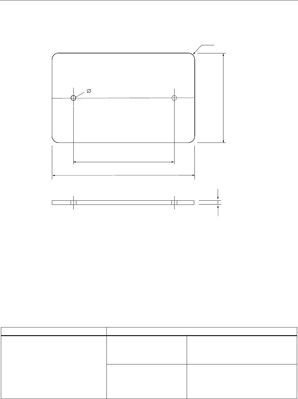
6.6.5 Dimension drawing
5
Figure 6-14 RF360T dimension drawing
Dimensions in mm
6.7 SIMATIC RF370T
6.7.1 Features
The SIMATIC RF370T transponder is a passive (i.e. battery-free) data carrier in a square
type of construction.
RF370T Characteristics
Field of application Identification tasks on assembly lines in
harsh industrial environments, suitable for
larger ranges,
e.g. automotive industry
Memory Read-only area:
4 byte UID
read/write memory:
32/64 KB
OTP 1) memory: 20 bytes
RF300 transponder
6.7 SIMATIC RF370T
SIMATIC RF300
152 System Manual, 11/2009 - Zwischenstand 17.09.2009, A5E01642529-04
RF370T Characteristics
Read/write range Refer to SectionField data of RF300
transponders (Page 41)
Assembly Direct assembly on metal or flush-mounting
is possible (with two M5 screws)
Degree of protection IP68
IPx9K
High resistance to mineral oils, lubricants and cleaning
agents
1) OTP: One Time Programmable
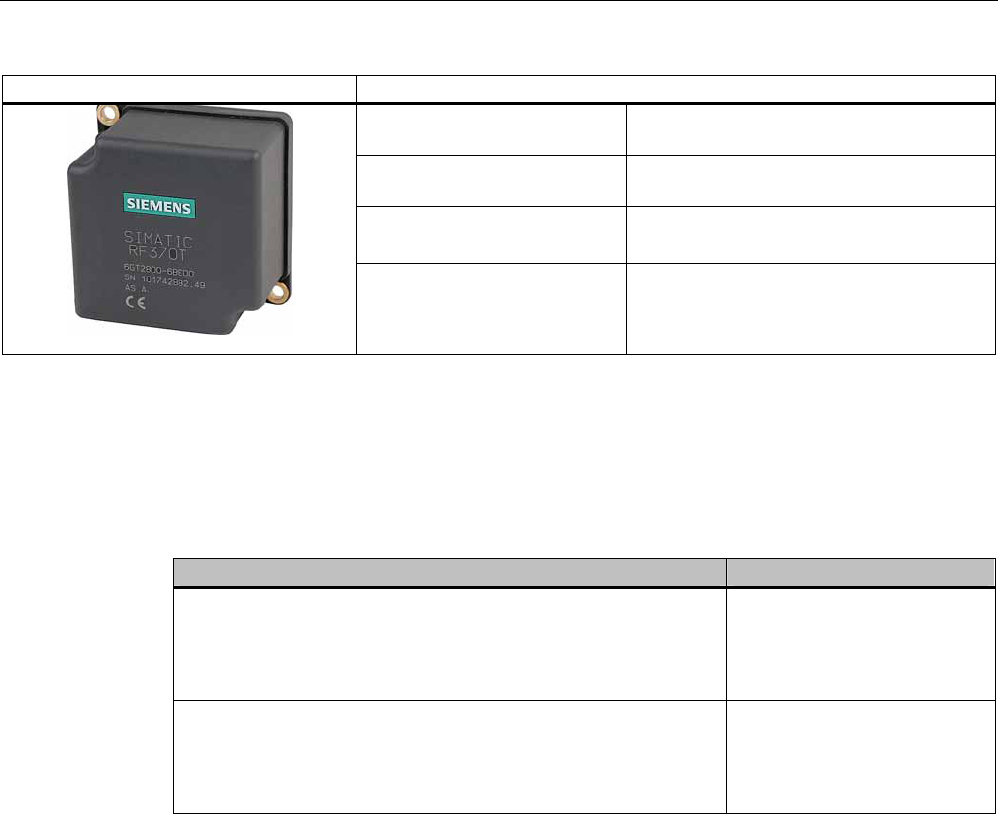
6.7.2 Ordering data
Table 6- 10 Ordering data RF370T
RF370T Order number
IP68
Memory size: 32 KB FRAM
Operating temperature: -25 to +85 °C
Dimensions: 75 x 75 x 40 (L x W x H, in mm)
6GT2800-5BE00
IP68
Memory size: 64 KB FRAM
Operating temperature: -25 to +85 °C
Dimensions: 75 x 75 x 40 (L x W x H, in mm)
6GT2800-6BE00
6.7.3 Mounting on metal
Direct mounting of the RF370T on metal is permitted.
RF300 transponder
6.7 SIMATIC RF370T
SIMATIC RF300
System Manual, 11/2009 - Zwischenstand 17.09.2009, A5E01642529-04 153
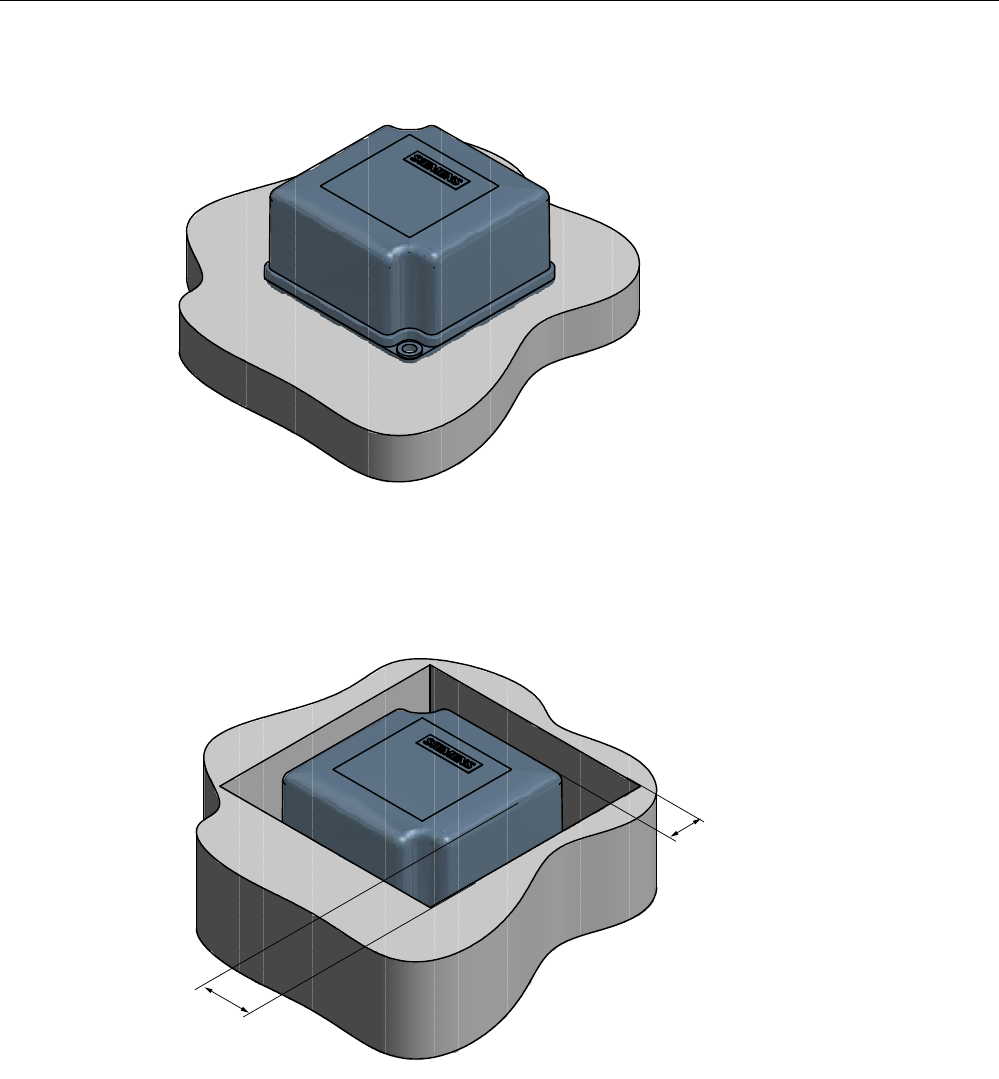
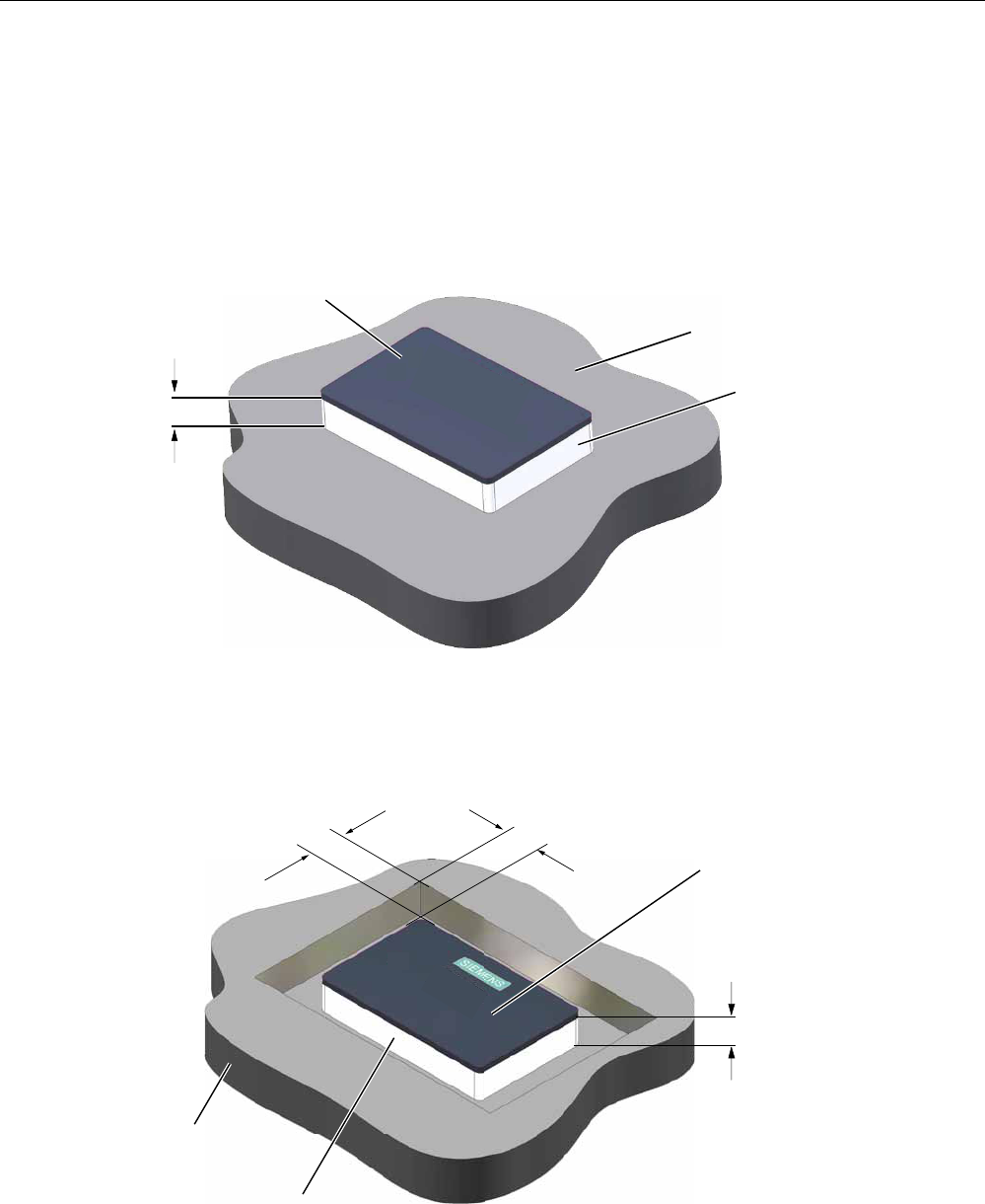
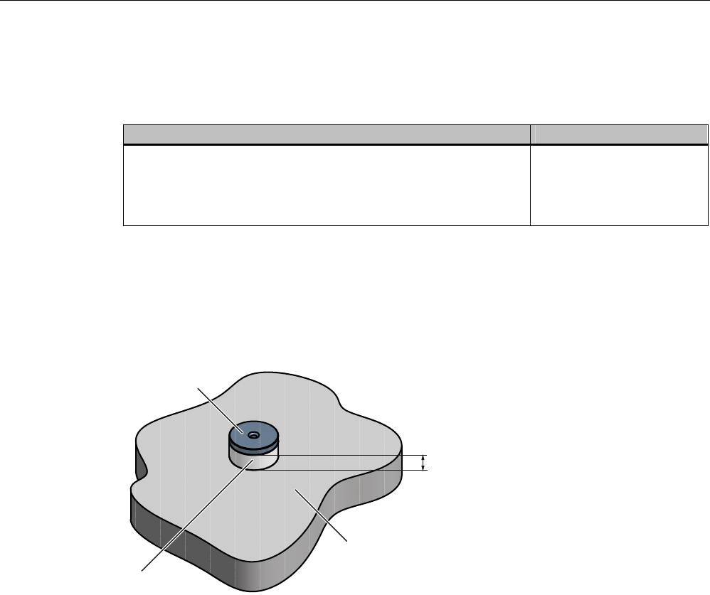
Mounting of RF370T on metal
Figure 6-15 Mounting of RF370T on metal
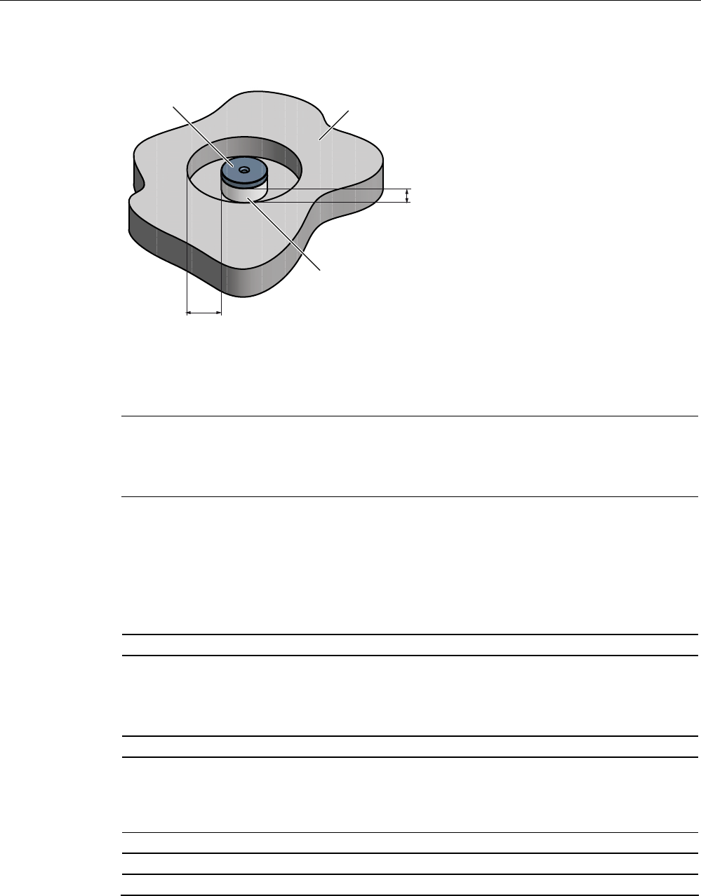
Flush-mounting of RF370T in metal:
D
D
Figure 6-16 RF370T flush-mounted in metal
The standard value for a is ≥ 20 mm. At lower values, the field data change significantly,
resulting in a reduction in the range.

RF300 transponder
6.7 SIMATIC RF370T
SIMATIC RF300
154 System Manual, 11/2009 - Zwischenstand 17.09.2009, A5E01642529-04
6.7.4 Mounting instructions
It is essential that you observe the instructions in the Section Installation guidelines
(Page 62).
Properties Description
Type of installation Screw fixing (two M5 screws)
Tightening torque < 1.2 Nm (at room temperature)
6.7.5 Technical data for RF370T with 32 KB FRAM
Table 6- 11 Technical specifications for RF370T with 32 KB FRAM/64 KB FRAM
Memory size 32 KB/64 KB
Memory organization Blocks of 8 bits/byte-by-byte
Serial number 4 bytes (fixed code)
Application memory 32765 bytes r/w (32 KB)
65276 bytes r/w (64 KB)
Memory configuration
OTP 1) memory 20 bytes
Storage technology FRAM / EEPROM
MTBF (Mean Time Between Failures)
in years
1200
Write cycles, at +40 °C Virtually unlimited (>1010)
Read cycles Virtually unlimited (>1010)
Read Approx. 0.13 ms/byte Data transmission time
Write Approx. 0.13 ms/byte
Data retention in years > 10
Read/write distance Dependent on the reader used [see Chapter Field data of
RF300 transponders (Page 41)]
Multitag capability max. 4 transponders
Recommended spacing from metal can be directly mounted on metal
Power supply Inductive, without battery
Degree of protection to EN 60529 IPx9K
Shock resistant to EN 60721-3-7 50 g
Vibration resistant to EN 60721-3-7 20 g
Torsion and bending load Not permissible continuously
Enclosure dimensions 75 x 75 x 40 mm (L x W x H)
Color Anthracite
Material PA12
Fixing Two M5 screws
Operation -25 °C to +85 °C Ambient temperature
Transport and storage -40°C to +85°C
RF300 transponder
6.7 SIMATIC RF370T
SIMATIC RF300
System Manual, 11/2009 - Zwischenstand 17.09.2009, A5E01642529-04 155
Weight Approx. 200 g
1) OTP: One Time Programmable; single write
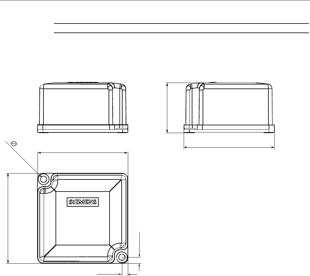
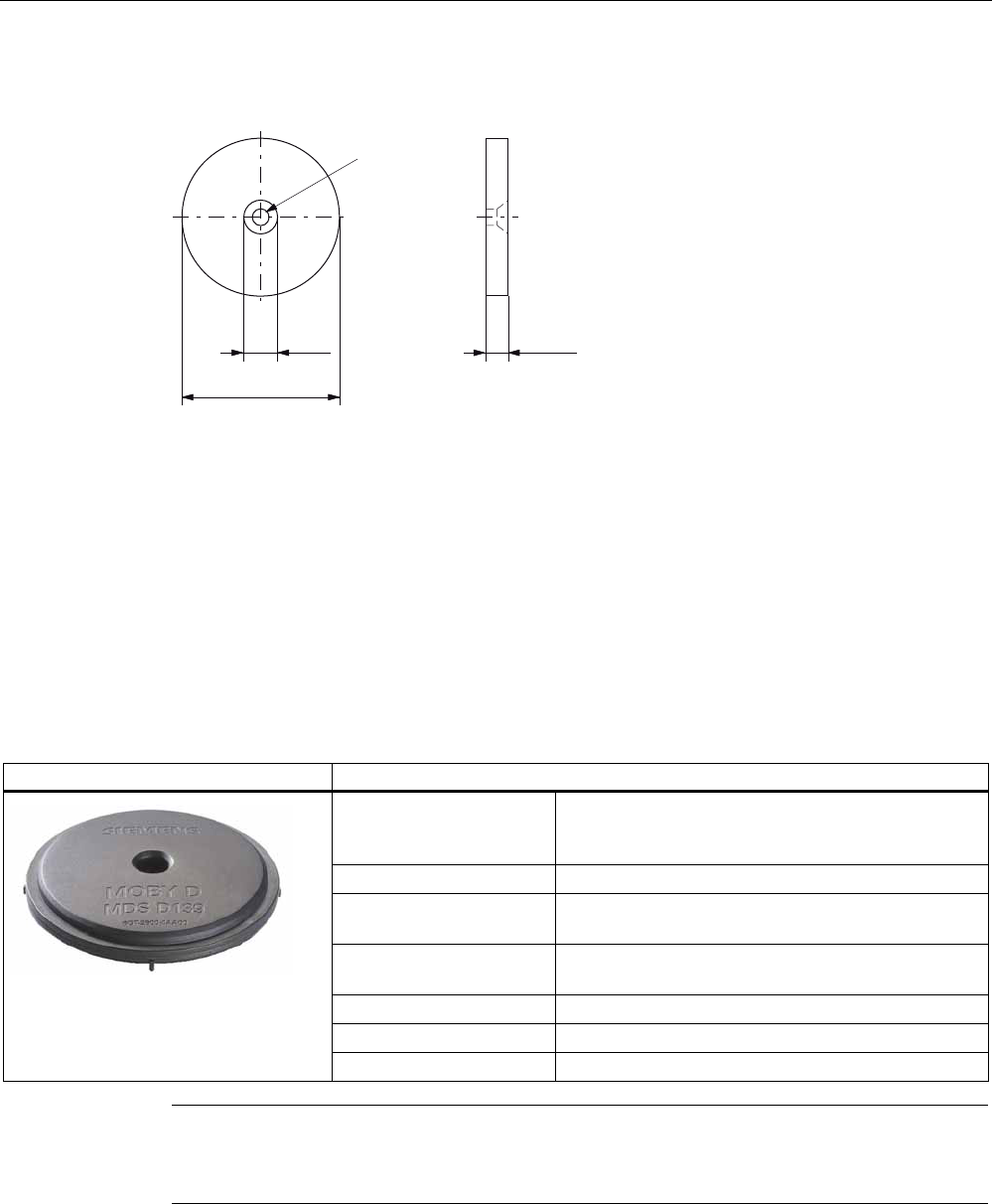
6.7.6 Dimensional drawing
Figure 6-17 RF370T dimension drawing
Dimensions in mm (inches in brackets)
RF300 transponder
6.8 SIMATIC RF380T
SIMATIC RF300
156 System Manual, 11/2009 - Zwischenstand 17.09.2009, A5E01642529-04
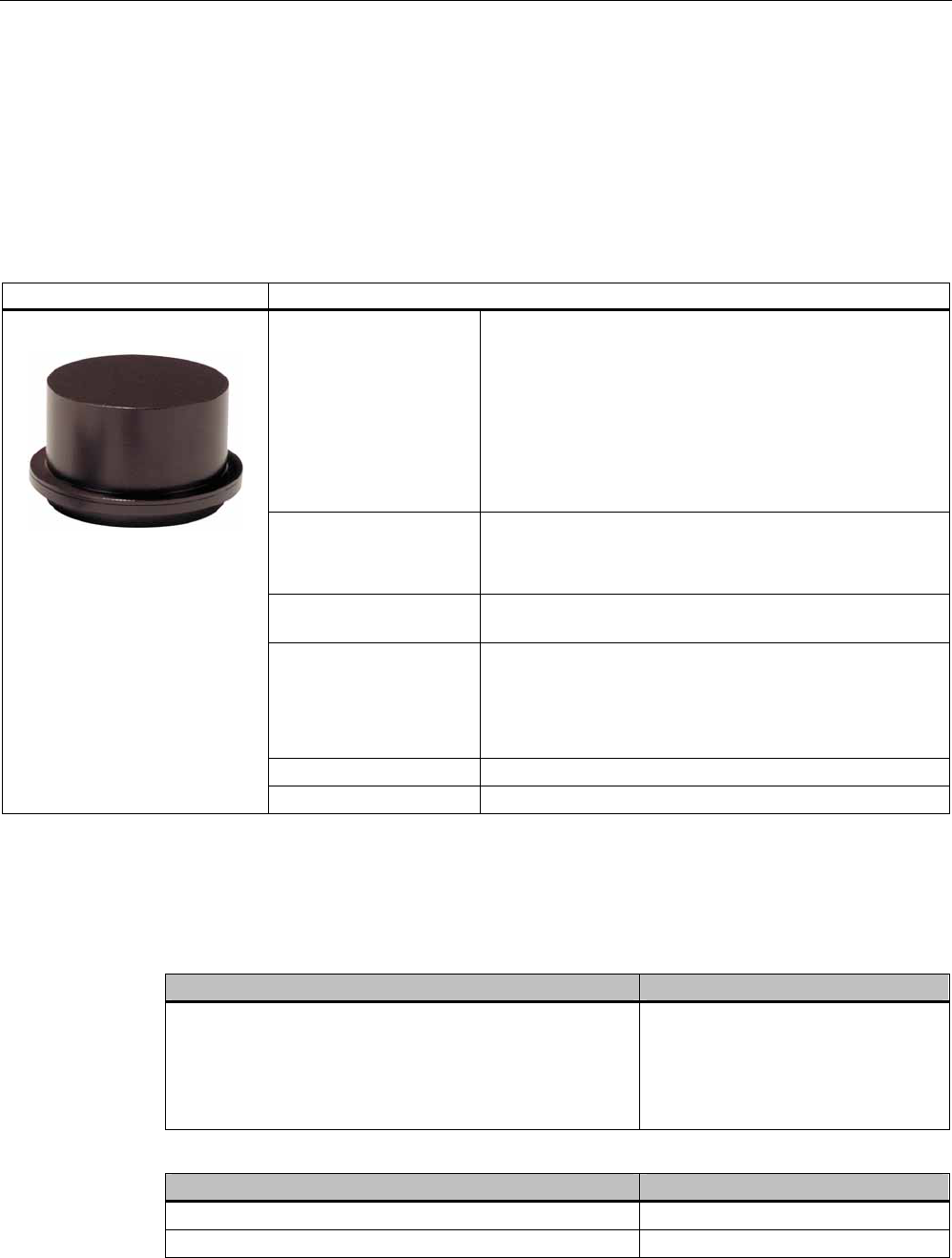
6.8 SIMATIC RF380T
6.8.1 Features
The SIMATIC RF380T transponder is an extremely rugged and heat-resistant round data
carrier suitable e.g. for applications in the automotive industry.
SIMATIC RF380T transponder Characteristics
Field of application Identification tasks in applications (e.g. automotive industry)
with cyclic high temperature stress > 85 °C and < 220 °C
Typical applications:
Primer coat, electrolytic dip area, cataphoresis with the
associated drying furnaces
Top coat area with drying furnaces
Washing areas at temperatures > 85°C
Other applications with higher temperatures
Memory Read-only area (4 bytes UID)
Read/write memory (32 KB)
OTP 1) memory (20 bytes)
Read/write range Refer to SectionField data of RF300 transponders
(Page 41)
Assembly Direct assembly on metal or flush-mounting is possible.
The transponder can be secured using a special holder
(see installation guidelines, section on RF380T).
The tag size is designed such that it can be secured on
a skid or also directly on a body.
Degree of protection IP 68
High resistance to mineral oils, lubricants and cleaning agents
1) OTP: One Time Programmable
6.8.2 Ordering data
RF380T Order number
IP68
Memory size 32 KB FRAM (read/write) and 4 byte
EEPROM
Operating temperature -25 … +200 °C (cyclic)
Dimensions: 114 x 83 (ØxH in mm)
6GT2800-5DA00
Accessories for RF380T Order number
Holder (short version) 6GT2090-0QA00
Holder (long version) 6GT2090-0QA00-0AX3
RF300 transponder
6.8 SIMATIC RF380T
SIMATIC RF300
System Manual, 11/2009 - Zwischenstand 17.09.2009, A5E01642529-04 157
Accessories for RF380T Order number
Covering hood 6GT2090-0QB00
Universal holder 6GT2590-0QA00
6.8.3 Installation guidelines for RF380T
It is essential that you observe the instructions in the Section Installation guidelines
(Page 62).
The following section only deals with features specific to the SIMATIC RF380T.
6.8.3.1 Mounting instructions
NOTICE
Only use tag with original holder
You are strongly recommended to only use the tag with the original holder specified. Only
this holder guarantees that the data memory observes the listed values for shock, vibration
and temperature. A protective cover is recommendable for applications in paint shops.
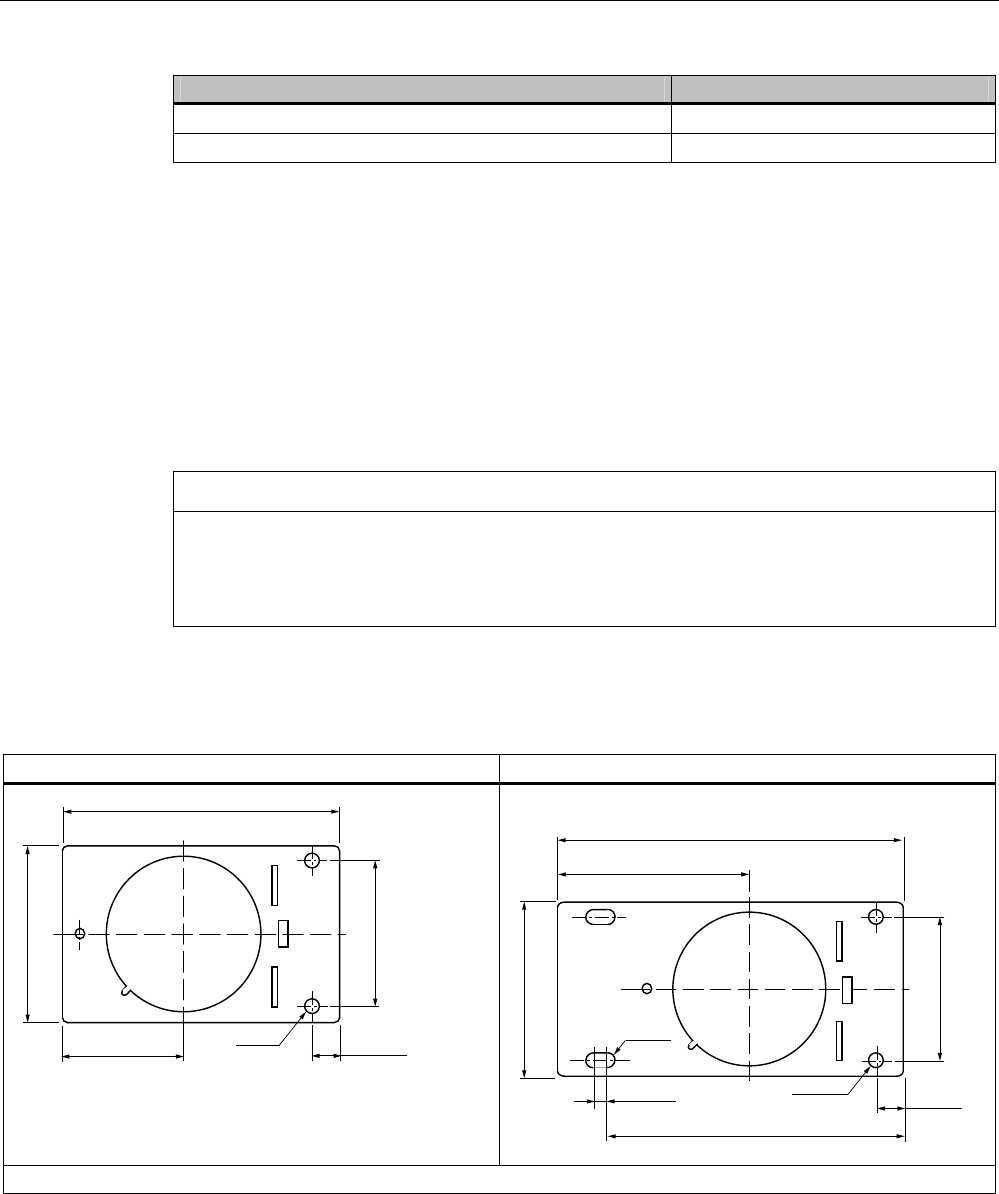
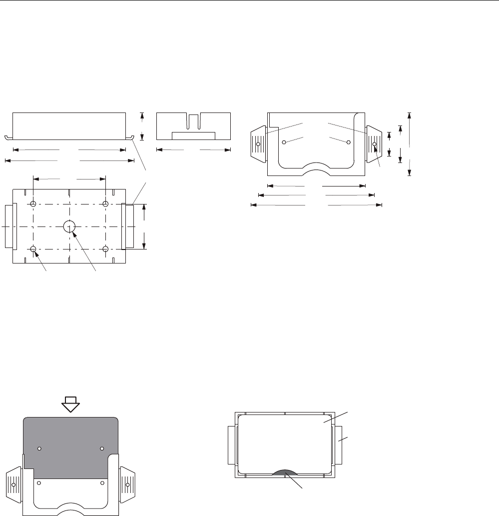
Data memory holder
Short version (6GT2 090-0QA00) Long version (6GT2090-0QA00-0AX3)
Material: V2A sheet-steel with thickness 2.5 mm BI 2.5 DIN 59382 1.4541
RF300 transponder
6.8 SIMATIC RF380T
SIMATIC RF300
158 System Manual, 11/2009 - Zwischenstand 17.09.2009, A5E01642529-04
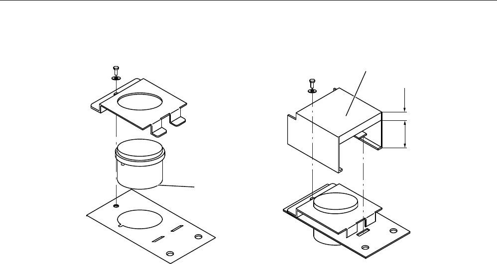
Assembly of data memory with holder
$QWHQQDVLGHRIWDJ
&RYHURSWLRQDO
*74%
Figure 6-18 Assembly of tag with holder
Scope of supply
The holder is provided with all mounting parts and a mounting diagram. Mounting screws for
securing the holder are not included. The mounting screws are of diameter M 10. The
minimum length is 25 mm. The optional cover can be used for the long and short versions of
the holder.
RF300 transponder
6.8 SIMATIC RF380T
SIMATIC RF300
System Manual, 11/2009 - Zwischenstand 17.09.2009, A5E01642529-04 159
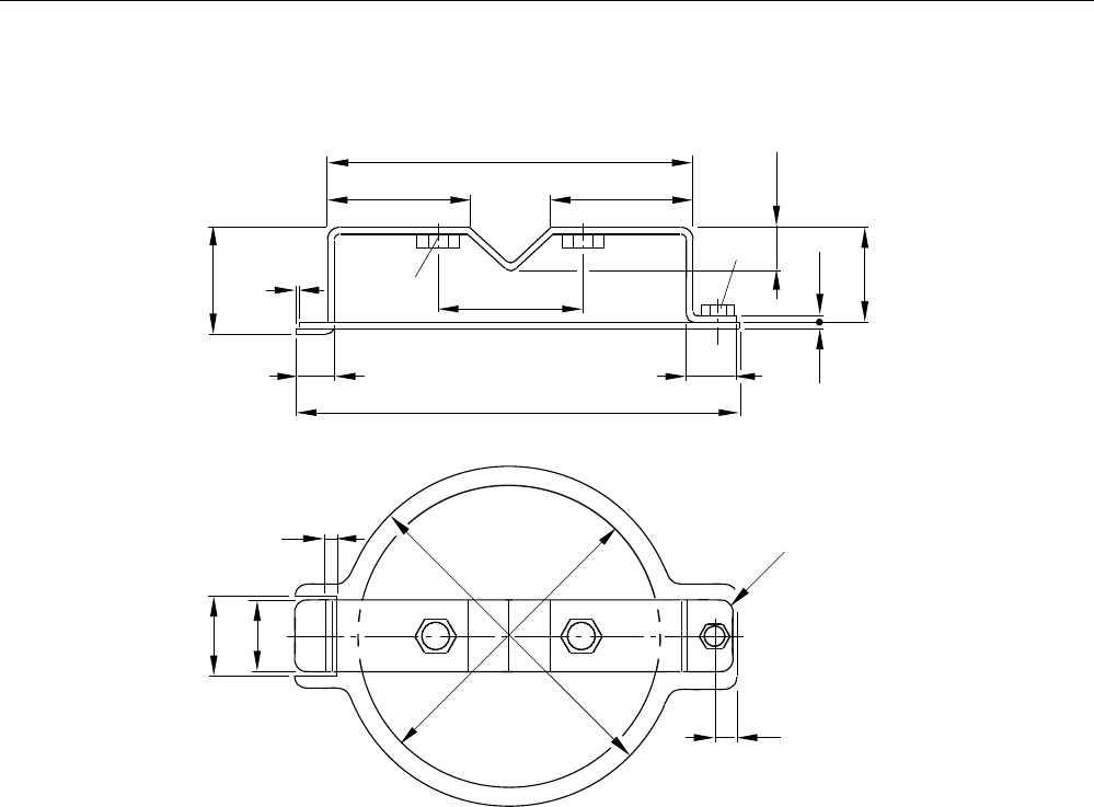
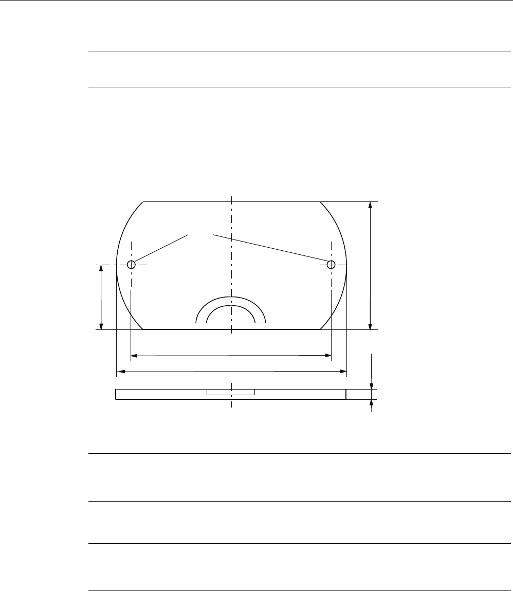
Universal holder
0
0
5
Figure 6-19 Universal holder 6GT2590-0QA00
6.8.3.2 Metal-free area
Direct mounting of the RF380T on metal is permitted.
RF300 transponder
6.8 SIMATIC RF380T
SIMATIC RF300
160 System Manual, 11/2009 - Zwischenstand 17.09.2009, A5E01642529-04
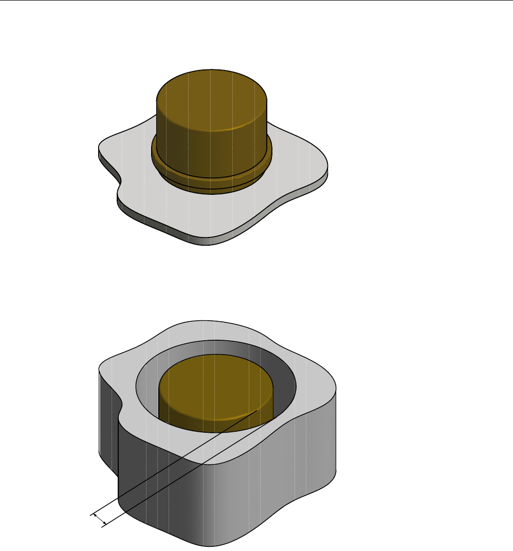
Mounting of RF380T on metal
Figure 6-20 Mounting of RF380T on metal
Flush-mounting of RF380T in metal:
D
Figure 6-21 RF380T flush-mounted in metal
The standard value for a is ≥ 40 mm. At lower values, the field data change significantly,
resulting in a reduction in the range.
RF300 transponder
6.8 SIMATIC RF380T
SIMATIC RF300
System Manual, 11/2009 - Zwischenstand 17.09.2009, A5E01642529-04 161
6.8.4 Configuring instructions
6.8.4.1 Temperature dependence of the transmission window
The guidelines in Section "Planning the RF300 system" apply to configuration of heat-
resistant data memories, with the exception of the limit distance and field length at
temperatures above 85 °C.
Calculation of transmission window with heat-resistant data memories
The factor 0.8 is required for calculating the transmission window, and takes into account
production tolerances and temperature influences of to 85 °C.
An additional correction factor C must be included in the calculation at temperatures > 85 °C
(up to 110 °C):
L Field length
Sg Limit distance tag - reader
VTag Tag speed
C Correction factor at temperatures > 85 °C
(cf. following picture with correction factor C depending on temperature)
tv Tag dwell time
RF300 transponder
6.8 SIMATIC RF380T
SIMATIC RF300
162 System Manual, 11/2009 - Zwischenstand 17.09.2009, A5E01642529-04
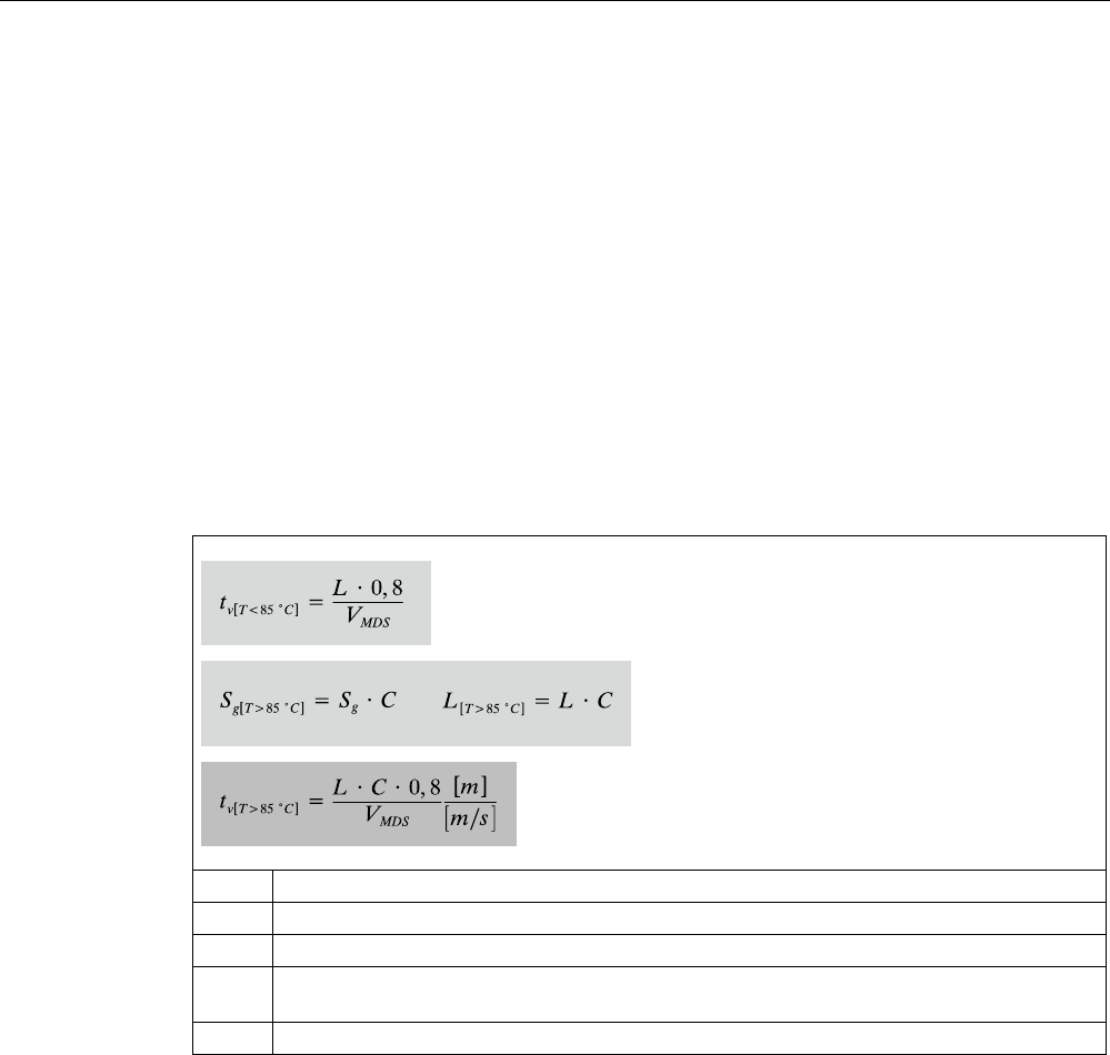
&>FRUUHFWLRQIDFWRU@
7>r&@
5)7
Figure 6-22 Correction factor C depending on temperature
The following diagram shows the reduction in the limit distance and field length at increased
processing temperatures (internal temperature of tag):
,QWHUQDOWHPSHUDWXUH>r&@
5)7
>@
Figure 6-23 Reduction in field length and limit distance
The reduction in the field data at higher temperatures is due to the increased current
consumption of the electronics.

RF300 transponder
6.8 SIMATIC RF380T
SIMATIC RF300
System Manual, 11/2009 - Zwischenstand 17.09.2009, A5E01642529-04 163
6.8.4.2 Temperature response in cyclic operation
At ambient temperatures (Tu) up to 110 °C, cyclic operation is not necessary, i.e. up to this
temperature, the transponder can be in constant operation.
Note
Calculation of the temperature curves
Calculation of the temperature curves or of a temperature profile can be carried out on
request by Siemens AG. Exact knowledge of the internal temperature facilitates
configuration for time-critical applications.
You can also carry out the calculation with the aid of the "SIMATIC RF Temperature
Calculator" on the "RFID Systems Software & Documentation" CD [see Accessories
(Page 257)].
Ambient temperatures > 110 °C
NOTICE
Cancellation of warranty
The internal temperature of the data memory must not exceed the critical threshold of 110
°C. Each heating phase must be followed by a cooling phase. No warranty claims will
otherwise be accepted.
Some limit cycles are listed in the table below:
Table 6- 12 Limit cycles of data memory temperature
Tu (heating up) Heating up Tu (cooling down) Cooling down
220 °C 0.5 h 25 °C > 2 h
200 °C 1 h 25 °C > 2 h
190 °C 1 h 25 °C > 1 h 45 min
180 °C 2 h 25 °C > 5 h
170 °C 2 h 25 °C > 4 h
The internal temperature of the tag follows an exponential function with which the internal
temperature and the operability of the tag can be calculated in advance. This is particularly
relevant to temperature-critical applications or those with a complex temperature profile.
RF300 transponder
6.8 SIMATIC RF380T
SIMATIC RF300
164 System Manual, 11/2009 - Zwischenstand 17.09.2009, A5E01642529-04
Ambient temperatures > 220°C
NOTICE
Cancellation of warranty
The data memory must not be exposed to ambient temperatures > 220 °C. No warranty
claims will otherwise be accepted.
However, the mechanical stability is retained up to 230 °C!
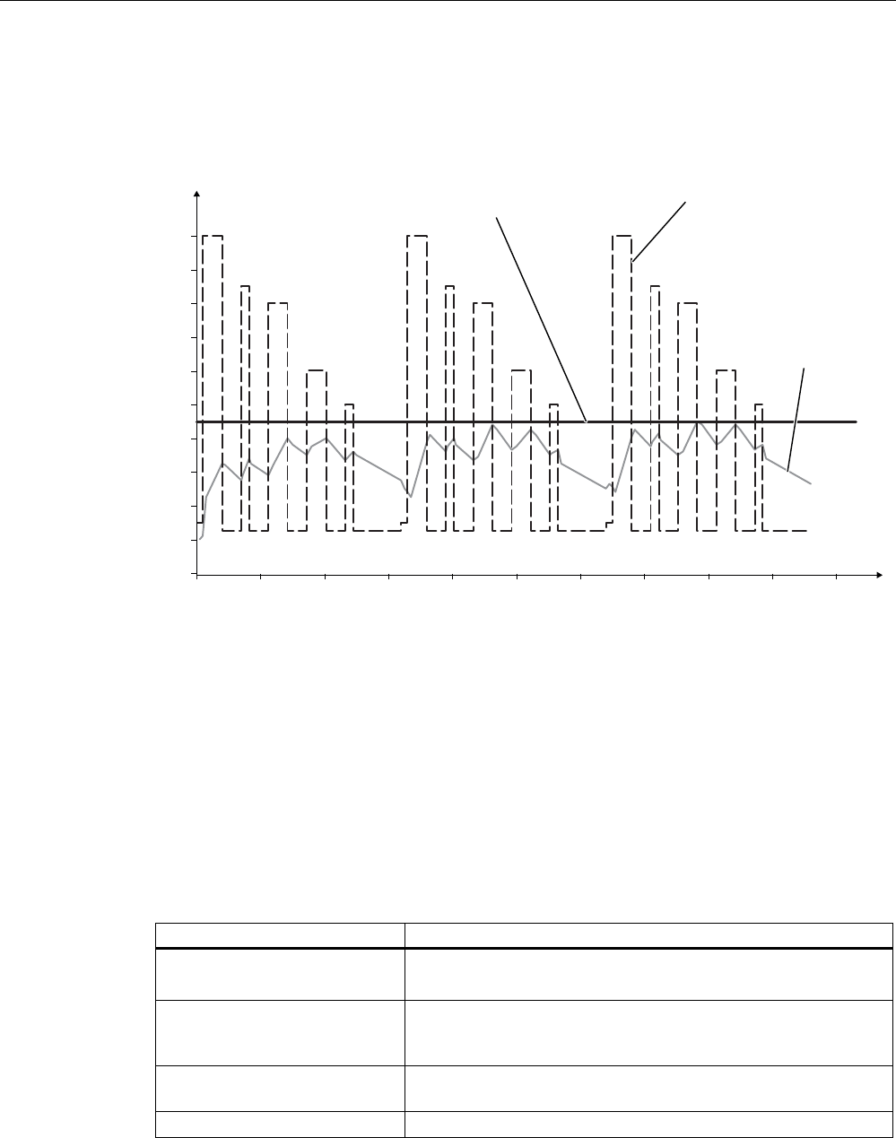
Example of a cyclic sequence
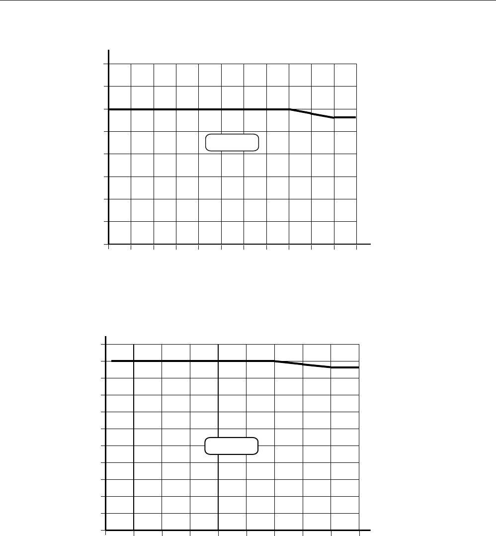
Table 6- 13 Typical temperature profile of an application in the paint shop
Start of tag at initial point Duration (min) Ambient temperature (°C)
Electrolytic dip 20 30
Electrolytic dip dryer 60 200
Transport 60 25
PVC dryer 25 170
Transport 60 25
Filler dryer 60 160
Transport 60 25
Top coat dryer 60 120
Transport 60 25
Wax dryer 25 100
Transport 150 25
7HPSHUDWXUH
.7/EDWK
7LPH
.7/GU\HU
39&GU\HU )LOOHUGU\HU
7RSFRDW
GU\HU :D[GU\HU
>PLQ@
>r&@
Figure 6-24 Graphic trend of temperature profile from above table
RF300 transponder
6.8 SIMATIC RF380T
SIMATIC RF300
System Manual, 11/2009 - Zwischenstand 17.09.2009, A5E01642529-04 165
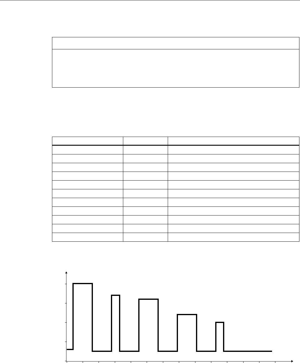
The simulation results in the following:
Following a simulation time of 36.5 hours, a total of 3 cycles were carried out, and an internal
temperature of 90 degrees Celsius was reached.
7HPSHUDWXUH
7LPH
$PELHQWWHPSHUDWXUH
0D[LPXPLQWHUQDOWHPSHUDWXUHRI
WDJIRUWKLVH[DPSOH
,QWHUQDO
WHPSHUDWXUH
RIWDJ
>PLQ@
>r&@
Figure 6-25 Complete temperature response due to simulation
6.8.5 Use of the transponder in the Ex protection area
The TÜV SÜD Automotive GmbH as approved test center as well as the TÜV SÜD Product
Service GmbH as certification center, identification number 0123, as per Article 9 of the
Directive of the European Council of 23 March 1994 (94/9/EC), has confirmed the
compliance with the essential health and safety requirements relating to the design and
construction of equipment and protective systems intended for use in hazardous areas as
per Annex II of the Directive. The essential health and safety requirements are satisfied in
accordance with the following standards:
Document Title
EN 60079-0: 2006
Electrical equipment for hazardous gas atmospheres -
Part 0: General requirements
EN 60079-15: 2005 Electrical equipment for hazardous gas atmospheres -
Part 15: Design, testing and identification of electrical equipment
with type of protection "n"
DIN VDE 0848-5: 2001
(in parts)
Safety in electrical, magnetic and electromagnetic fields -
Part 5: Explosion protection
ZLS SK 107.1 Central office of the states for safety; test components
RF300 transponder
6.8 SIMATIC RF380T
SIMATIC RF300
166 System Manual, 11/2009 - Zwischenstand 17.09.2009, A5E01642529-04
Identification
The identification of the electrical equipment as an enclosed unit is:
II 3G Ex nC IIB T5
-25°C to +70°C
Um = 30 V DC
The equipment is assigned the following references:
XXXYYYZZZ [= serial number, is assigned during production]
TPS 09 ATEX 1 459 X [= certificate number]
"No use of the equipment in the vicinity of processes generating high charges"
6.8.6 Use of the transponder in hazardous areas for gases
Temperature class delineation for gases
The temperature class of the transponder for hazardous areas depends on the ambient
temperature range:
Ambient temperature range Temperature class
-25 °C to +70 °C T5
WARNING
Ignitions of gas-air mixtures
When using the RF380T transponder, check to ensure that the temperature class is
observed in respect of the requirements of the area of application
Non-compliance with the permitted temperature ranges while using the transponder can
lead to ignitions of gas-air mixtures.
WARNING
Ignitions of gas-air mixtures
The maximum transmitting power of the transmitter used to operate the transponder must
not exceed 2 W.
Non-compliance with the permissible transmitting power can lead to ignitions of gas-air
mixtures.

RF300 transponder
6.8 SIMATIC RF380T
SIMATIC RF300
System Manual, 11/2009 - Zwischenstand 17.09.2009, A5E01642529-04 167
6.8.7 Installation and operating conditions for the hazardous area
a) Use of the equipment in the vicinity of processes generating high charges is not allowed.
b) The equipment must be mechanically protected when installed.
6.8.8 Technical specifications
Table 6- 14 RF380T with 32 KB FRAM
Memory size 32KB
Memory organization Blocks of 8 bits/byte-by-byte
Serial number 4 bytes (fixed code)
Application memory 32765 bytes r/w
Memory configuration
OTP 1) memory 20 bytes
Storage technology FRAM / EEPROM
MTBF (Mean Time Between Failures)
in years
1177
Write cycles, at +40 °C Virtually unlimited (>1010)
Read cycles Virtually unlimited (>1010)
Read Approx. 0.13 ms/byte Data transmission time
Write Approx. 0.13 ms/byte
Data retention > 10 years
Read/write distance Dependent on the reader used [see Chapter Field data of
RF300 transponders (Page 41)]
Multitag capability max. 4 transponders
Recommended spacing from metal can be directly mounted on metal
Power supply Inductive, without battery
Degree of protection to EN 60529 IP68
Shock resistant2) to EN 60721-3-7 50 g
Vibration2) to EN 60721-3-7 5 g
Direction-dependent No
Torsion and bending load Not permissible continuously
Enclosure dimensions (diam. x H in mm) 114 x 83
Color Brown
Material PPS
Fixing Holder to be ordered separately
During operation, continuously -25 °C to +110°C
During cyclic operation -25 °C to +220°C
Ambient temperature
Transport and storage -40°C to +110°C
Weight Approx. 900 g
1) OTP: One Time Programmable
2) Applies only in connection with original bracket
RF300 transponder
6.8 SIMATIC RF380T
SIMATIC RF300
168 System Manual, 11/2009 - Zwischenstand 17.09.2009, A5E01642529-04
6.8.9 Dimensional drawing
SIEMENS
6HFXULQJERUGHU
$QWHQQDHQG
Figure 6-26 Dimension drawing RF380T
Dimensions in mm (inches in brackets)
SIMATIC RF300
System Manual, 11/2009 - Zwischenstand 17.09.2009, A5E01642529-04 169
ISO transponder 7
ISO 15693-compatible transponders, such as the MDS Dxxx from the MOBY D range of
products, represent a cost-effective alternative to RF300 tags. The performance that can be
achieved with this (data rate, memory size), however, is considerably less than with RF300
tags (see Chapter Communication between communication module, reader and transponder
(Page 37)).
Operating with the following ISO tags from MOBY D is described in this manual:
● MDS D100
● MDS D124
● MDS D139
● MDS D160
● MDS D324
● MDS D421
● MDS D424
● MDS D428
● MDS D460
Compatible RF300 readers
ISO tags can currently only be processed using the following readers:
● SIMATIC RF310R (RS422) [6GT2801-1AB10]
● SIMATIC RF340R [6GT2801-2AB10]
● SIMATIC RF350R [6GT2801-4AB10]
● SIMATIC RF380R [6GT2801-3AB10]
ISO transponder
7.2 Memory configuration of the ISO tags
SIMATIC RF300
170 System Manual, 11/2009 - Zwischenstand 17.09.2009, A5E01642529-04
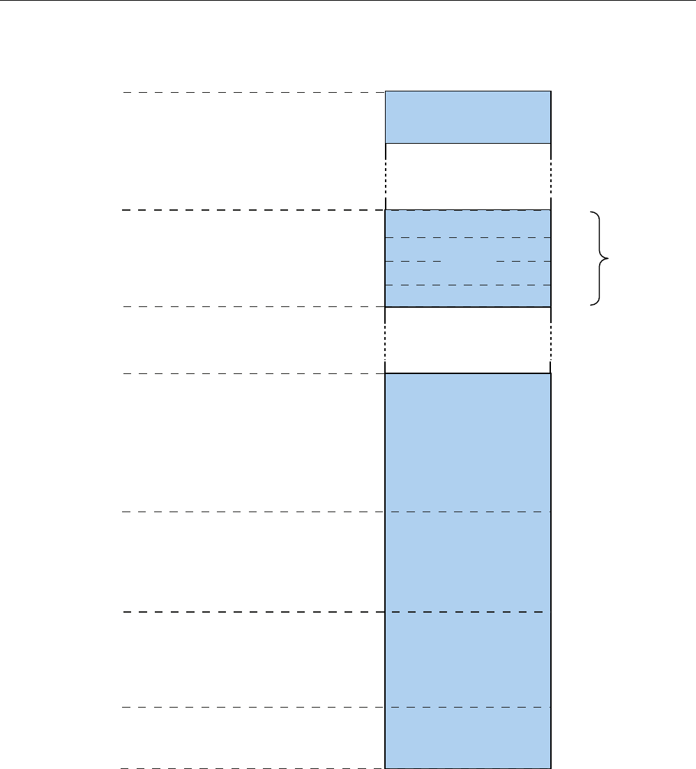
7.2 Memory configuration of the ISO tags
E\WHV
8,'UHDGRQO\
8VHUDUHD
UHDGZULWH
((3520
273
PD[
EORFNVRI
E\WHVHDFK
0'6'
7DJLW+),67/5,.
E\WH((3520
E\WHEORFNVL]H
E\WH)5$0
E\WHEORFNVL]H
,&2'(6/,
E\WH((3520
E\WHEORFNVL]H
,QILQHRQP\G
E\WH((3520
E\WHEORFNVL]H
0'6'
0'6'
0'6'
0'6'
))
)))
)))
')
)
))&
))
))
&)
)XMLWVX0%5
))
))
0'6'
1'6'
0'6'
0'6'
1) If the OTP area is used, there will be a correspondingly lower amount of user memory
available, because the OTP area always occupies the uppermost 16 bytes of the user memory.
Figure 7-1 Memory configuration of ISO tags

ISO transponder
7.2 Memory configuration of the ISO tags
SIMATIC RF300
System Manual, 11/2009 - Zwischenstand 17.09.2009, A5E01642529-04 171
Memory areas
Depending on the manufacturer of the transponder chip, the memory configuration of an ISO
tag consists of EEPROM memory of varying sizes. Except for transponders that are
equipped with a Fuijtsu 2k FRAM, these are equipped with only one FRAM.
The typical sizes are 112 bytes, 256 bytes, 992 bytes or 2000 bytes. Each ISO transponder
chip features an 8-byte unique serial number (UID, read only). This UID is transferred as an
8 byte value through a read command to address FFF0 with a length of 8.
OTP area
For the OTP area, a 16-byte address space is always reserved at the end of the memory
area. The blocks are divided up depending on the chip (see technical specifications). For the
user, this means that the corresponding addresses for the user data are not available to the
application when the OTP area is used.
A total of 4 block addresses ("mapped" addresses) are provided:
● FF80
● FF84
● FF88
● FF8C
A write command to this block address with a valid length (4, 8, 12, 16 depending on the
block address) protects the written data from subsequent overwriting.
Note
Exception - Fujitsu chip
This chip only has 8-byte blocks, which means that only 2 block addresses have to be
addressed: FF80 and FF88 (lengths 8 and 16).
NOTICE
OTP writing/locking should only be used in static operation.
NOTICE
Use of the OTP area is not reversible.
If you use the OPT area, you cannot undo it, because the OPT area can only be written to
once.

ISO transponder
7.3 MDS D100
SIMATIC RF300
172 System Manual, 11/2009 - Zwischenstand 17.09.2009, A5E01642529-04
7.3 MDS D100
7.3.1 Characteristics
The MDS D100 mobile data memory is a passive, maintenance-free transponder based on
the ISO 15693 standard with I-Code technology.
MDS D100 Characteristics
Field of application From simple identification such as electronic
barcode replacement/supplementation, through
warehouse and distribution logistics, right up to
product identification.
Memory EEPROM 128 bytes gross
112 bytes net capacity
Read/write range See Chapter Field data of ISO transponders
(Page 44).
Mounting on metal Not possible; recommended distance from
metal ≥ 20 mm
ISO standard 15693 with I-code technology
@ noch zu ergänzen: wo soll das wie hin?Befestigung des MDS D100 (...0AD10) Bohrung /
Stanzung max. 3,5 mm, Schraube nach DIN 4017: M3, Kopfdurchmesser max. 6 mm
7.3.2 Ordering data
Table 7- 1 Ordering data for MDS D100
MDS D100 Order number
Memory size: 112 byte EEPROM
Operating temperature: -25 °C … +80 °C
Dimensions: 85.6 x 54 x 0.9 (L x W x H, in mm)
ISO card
IP68
6GT2600-0AD10
Table 7- 2 Ordering data for MDS D100 accessory
MDS D100 accessory Order number
Spacers 6GT2190-0AA00
Fixing pocket 6GT2190-0AB00
Fixing pocket (cannot be mounted directly on metal) 6GT2390-0AA00
ISO transponder
7.3 MDS D100
SIMATIC RF300
System Manual, 11/2009 - Zwischenstand 17.09.2009, A5E01642529-04 173
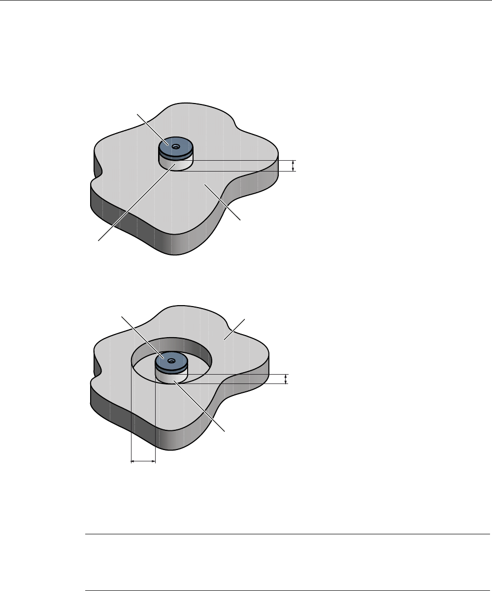
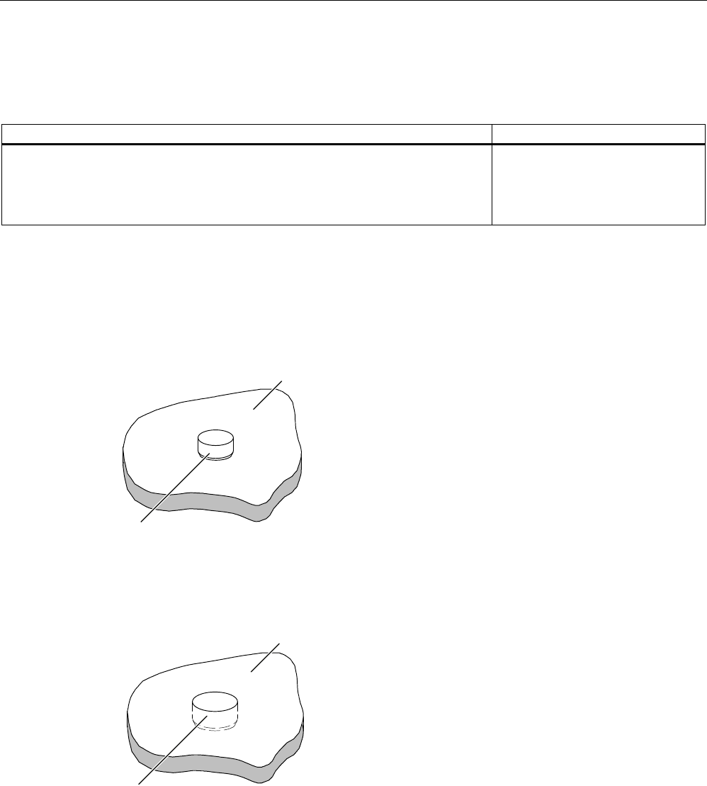
7.3.3 Mounting on metal
Direct mounting of the MDS D100 on metal is not allowed. A distance of ≥ 20 mm is
recommended. This can be achieved using the spacer 6GT2190-0AA00 in combination with
the fixing pocket 6GT2190-0AB00.
Mounting on metal
0HWDO
1RQPHWDO
'DWDPHPRU\
K
h ≥ 20 mm
Figure 7-2 Mounting of the MDS D100 on metal with spacer
Flush-mounting
1RQPHWDO
0HWDO
D
D
'DWDPHPRU\
K
h ≥ 20 mm
a ≥ 20 mm
Figure 7-3 Flush-mounting of MDS D100 in metal with spacer
ISO transponder
7.3 MDS D100
SIMATIC RF300
174 System Manual, 11/2009 - Zwischenstand 17.09.2009, A5E01642529-04
Note
If the minimum guide values (h) are not observed, a reduction of the field data results.
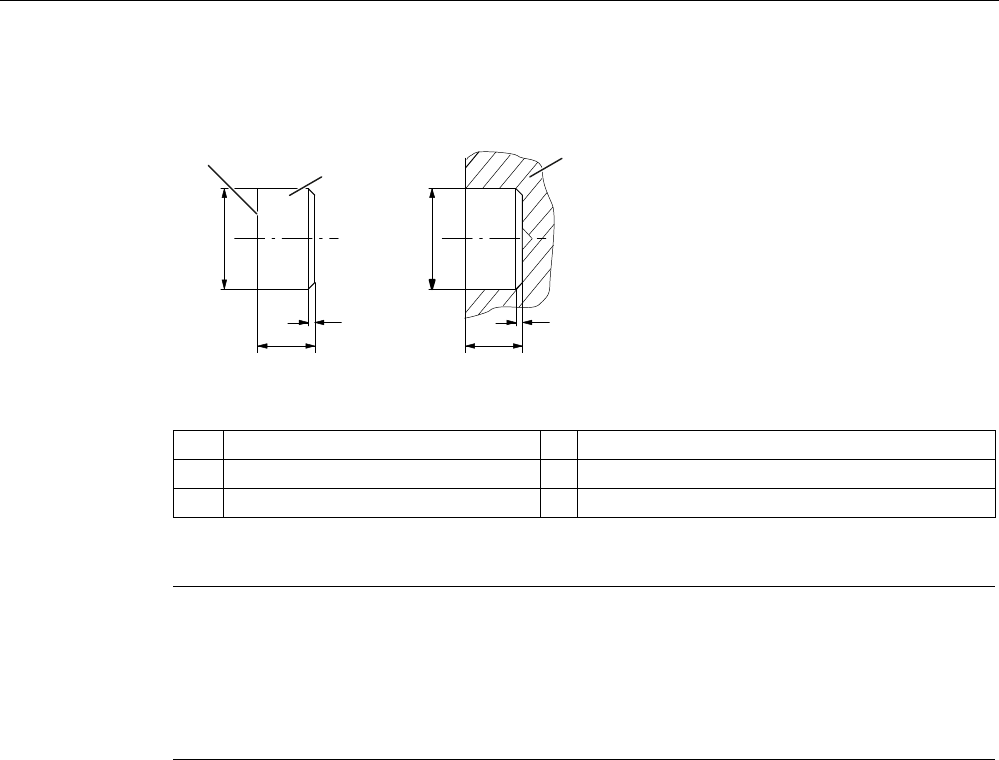
Fixing pocket for MDS D100
The fixing pocket is secured on a non-metallic surface with M4 countersunk head screws in
the holes provided.
s
s
s
s
s
Figure 7-4 Fixing pocket 6GT2390-0AA00 for MDS D100
Note
The fixing pocket shown here with Order No.: 6GT2 390-0AA00 is not suitable for use with
the spacer (6GT2 190-0AA00).
Note
When mounting the MDS D100 on metal, it is also possible to use the 6GT2 190-0AB00
fixing pocket, but only in combination with the 6GT2 190-0AA00 spacer.
ISO transponder
7.3 MDS D100
SIMATIC RF300
System Manual, 11/2009 - Zwischenstand 17.09.2009, A5E01642529-04 175
Fixing pocket with spacer for MDS D100
6,(0(16
/XJV
+ROGLQJNQREV
)L[LQJSRFNHW*7$%
)L[LQJEUDFNHW
'LPHQVLRQVNHWFK
6SDFHUV*7$$
0DWHULDO3$
'DWDPHPRU\
7KHWUDQVSRQGHULVLQVHUWHGLQWRWKH
IL[LQJSRFNHW7KHHDUVDUHPRYHGE\
rDQGLQVHUWHGLQWRWKHVSDFHU7KH
IL[LQJSRFNHW
PXVWEHDOLJQHGVXFKWKDWLW
FRYHUVWKHWUDQVSRQGHUVHH)LJXUH
/RFNLQJLVDXWRPDWLF
5HDVVHPEO\LQVWUXFWLRQV
7KHIL[LQJSRFNHWLVDWWDFKHGWRDQRQPHWDO
EDVHE\WKHHDUV7KLVFDQEH
DFKLHYHGZLWK
6FUHZVLQWKHKROHVSURYLGHG
5LYHWVLQWKHKROHVSURYLGHG
1DLOVWKURXJKWKHKROHV
7DFNVWKURXJKWKHSODVWLFRIWKHHDUV
3XVKLQJLQWRWKHVSDFHUV
7KHHDUVFDQEHPRYHGWKURXJK
XSWRr
7KHWUDQVSRQGHULV
LQVHUWHGLQWRWKH
IL[LQJSRFNHW
/RFNLQJLV
FDUULHGRXWXVLQJ
WKH
KROGLQJNQREVLQ
WKHIL[LQJ
SRFNHW
6SDFHUV
)L[LQJSRFNHW
7UDQVSRQGHUZLWKIL[LQJSRFNHW 7UDQVSRQGHUZLWKIL[LQJSRFNHWDQG
VSDFHUFRQQHFWHGWRJHWKHU
7KHVSDFHUFDQEHGLUHFWO\PRXQWHGRQPHWDO,QFRPELQDWLRQZLWKWKH
IL[LQJSRFNHWDQRQPHWDOGLVWDQFHRIPPUHVXOWVEHWZHHQWKHWUDQVSRQGHUDQGPHWDO
0RXQWLQJ
:LWKRUVFUHZV0
:LWKUXEEHUVRQWKHKROGLQJFOLSVHJRQPHVKER[HV
:LWKFDEOHWLHVRQWKHKROGLQJFOLSVHJRQPHVKER[HV
Figure 7-5 Dimensions of the spacer and fixing pocket 6GT2190-0AB00 for MDS 100

ISO transponder
7.3 MDS D100
SIMATIC RF300
176 System Manual, 11/2009 - Zwischenstand 17.09.2009, A5E01642529-04
7.3.4 Technical data
Table 7- 3 Technical data for MDS D100
Memory size 128 bytes
Memory configuration
Serial number
Configuration memory
Application memory
8 bytes (fixed code)
8 bytes
112 bytes
Storage technology EEPROM
Memory organization EEPROM 128 bytes gross
112 bytes net capacity
When using the OPT area, 16 bytes of it must be
subtracted in 4 byte blocks
Protocol according to ISO 15693
Data retention (at +40 °C) 10 years
MTBF (at +40 °C) 2 x 10⁶ hours
Read cycles Unlimited
Write cycles, typical 1 000 000
Write cycles, min. 100 000
Read/write distance (Sg) See Chapter Field data of ISO transponders (Page 44).
Distance from metal min. 20 mm (approx. 30% reduction of the field data)
Multitag capability Yes
Power supply Inductive power transmission (without battery)
Degree of protection to EN 60529 IP68
Vibration ISO 10373/ISO 7810
Torsion and bending load ISO 10373/ISO 7816-1
Mechanical design
Color
Material
Dimensions (L x W x H) in mm
Laminated plastic card, printable on both sides
White/petrol
PC
85.6 x 54 x 0.9
Fixing Adhesive, fixing pocket
Ambient temperature
During operation
Transport and storage
-25 °C to +80 °C
-25 °C to +80 °C
Weight, approx. 5 g
ISO transponder
7.4 MDS D124
SIMATIC RF300
System Manual, 11/2009 - Zwischenstand 17.09.2009, A5E01642529-04 177
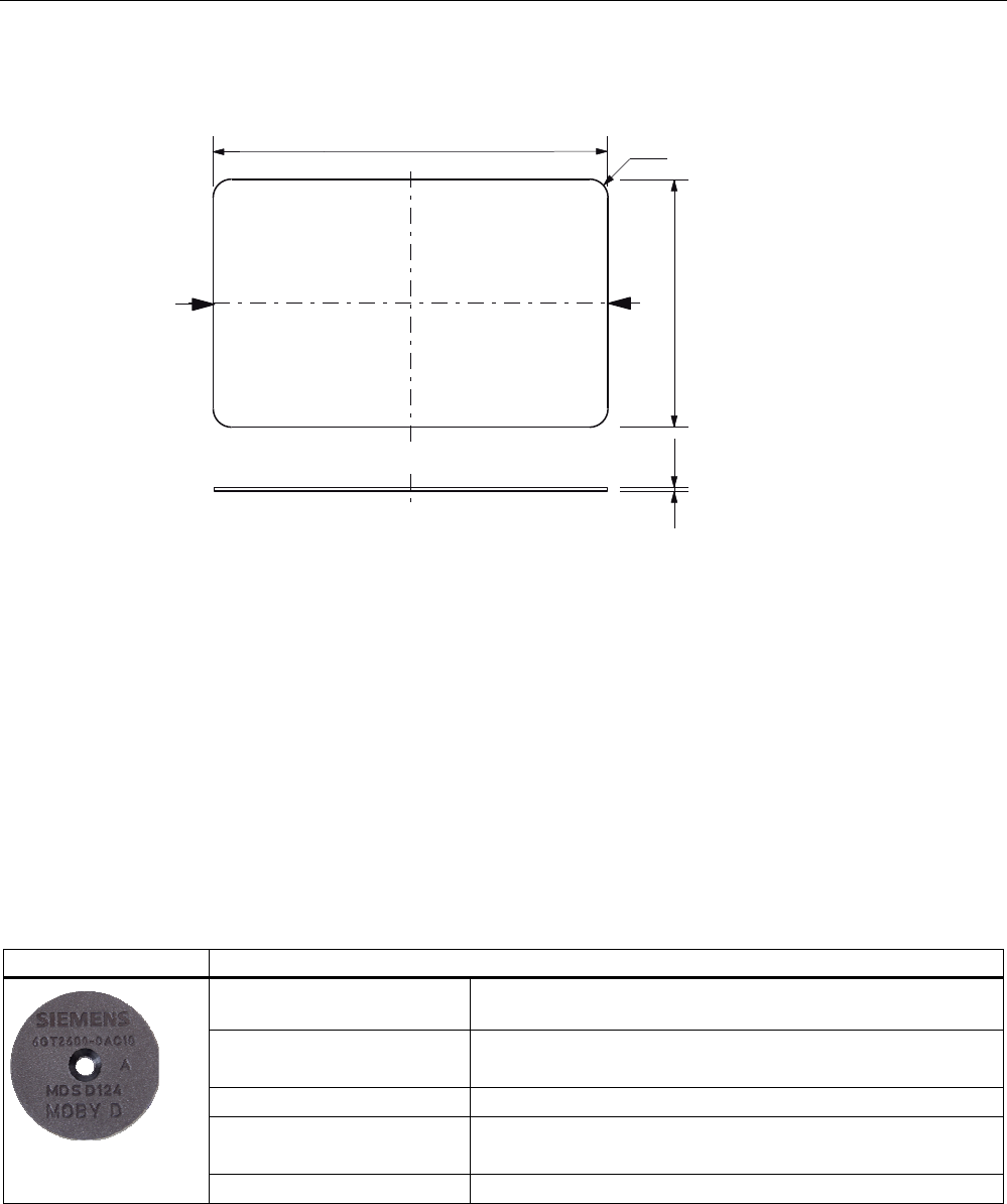
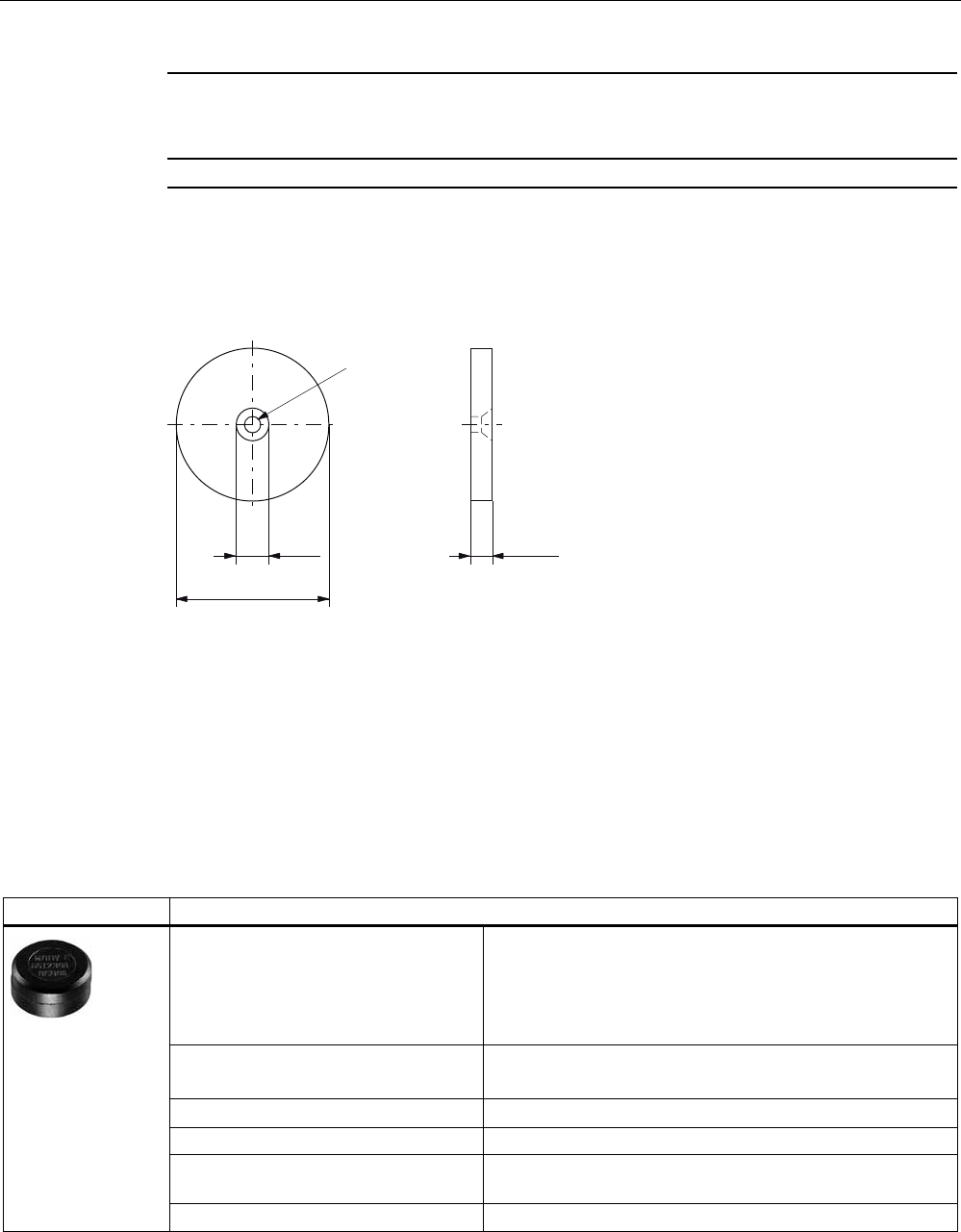
7.3.5 Dimension drawing
5
$$
s
s
s
Dimensions in mm
Figure 7-6 MDS D100 dimension drawing
7.4 MDS D124
7.4.1 Characteristics
@ Neuer Kopf - noch nichts geändert! Input fehlt nochThe MDS D124 is a passive,
maintenance-free transponder based on the ISO 15693 standard with I-Code technology.
This mobile data memory can also be easily used in harsh environments under extreme
environmental conditions (e.g. with higher temperature load).
MDS D124 Characteristics
Field of application Application areas in production and distribution logistics and
product identification
Memory EEPROM 128 bytes gross
112 bytes net capacity
Read/write range See Chapter Field data of ISO transponders (Page 44).
Mounting on metal Not possible:
Recommended distance from metal ≥ 25 mm
ISO standard 15693 with I-code technology
ISO transponder
7.4 MDS D124
SIMATIC RF300
178 System Manual, 11/2009 - Zwischenstand 17.09.2009, A5E01642529-04
7.4.2 Ordering data
Table 7- 4 Ordering data for MDS D124
MDS D124 Order number
Memory size: 112 byte EEPROM user memory
Operating temperature: -25 °C … +125 °C
Dimensions: Ø = 27 mm x 4 mm
IP67
6GT2600-0AC10
7.4.3 Mounting on metal
Mounting on metal
1RQPHWDO
0HWDO
'DWDPHPRU\
K
h ≥ 25 mm
Figure 7-7 Mounting of the MDS D124 on metal with spacer
ISO transponder
7.4 MDS D124
SIMATIC RF300
System Manual, 11/2009 - Zwischenstand 17.09.2009, A5E01642529-04 179
Flush-mounting
D
'DWDPHPRU\ 0HWDO
1RQPHWDO
K
h ≥ 25 mm
a ≥ 25 mm
Figure 7-8 Flush-mounting of MDS D124 in metal with spacer
Note
If the minimum guide values (h) are not observed, a reduction of the field data results. It is
possible to mount the MDS with metal screws (M3 countersunk head screws). This has no
tangible impact on the range.
7.4.4 Technical specifications
Table 7- 5 Technical data for MDS D124
Memory size 128 bytes
Memory configuration
Serial number
Configuration memory
Application memory
8 bytes (fixed code)
8 bytes
112 bytes
Storage technology EEPROM
Memory organization EEPROM 128 bytes gross
112 bytes net capacity
When using the OPT area, 16 bytes of it must be
subtracted in 4 byte blocks
Protocol according to ISO 15693
Data retention (at +40 °C) 10 years
MTBF (at +40 °C) ≥ 1.5 x 10⁶ hours

ISO transponder
7.4 MDS D124
SIMATIC RF300
180 System Manual, 11/2009 - Zwischenstand 17.09.2009, A5E01642529-04
Data transmission rate
Read
Write
Approx. 3.5 ms/byte
Approx. 9.5 ms/byte
Read cycles Unlimited
Write cycles, typical 1 000 000
Write cycles, min. 100 000
Read/write distance (Sg) See Chapter Field data of ISO transponders
(Page 44).
Distance from metal min. 25 mm (approx. 30% reduction of the field data)
Multitag capability Yes
Power supply Inductive power transmission
(without battery)
Degree of protection to EN 60529 IP67
Shock according to EN 60721-3-7, Class 7M3
total shock response spectrum, Type II
100 g
Vibration-resistant to EN 60721-3-7, Class
7M3
20 g
Torsion and bending load Not permissible
Dimensions (D x H) in mm 27 x 4
Color Black
Material Epoxy casting resin
Fixing Adhesive, M3 screw
Tightening torque at +20 °C ≤ 1 Nm
(at high temperatures, the expansion coefficients of
the materials used must be taken into account)
Ambient temperature
During operation
Transport and storage
-25 °C to +125 °C
-40 °C to +150 °C
Weight, approx. 5 g
ISO transponder
7.5 MDS D139
SIMATIC RF300
System Manual, 11/2009 - Zwischenstand 17.09.2009, A5E01642529-04 181
7.4.5 Dimension drawing
s
s
Dimensions in mm
Figure 7-9 Dimension drawing of MDS D124
7.5 MDS D139
7.5.1 Characteristics
The MDS D139 is a passive, maintenance-free transponder based on the ISO standard
15693.
MDS D139 Characteristics
Field of application Applications in production logistics and in assembly
lines subject to high temperatures (up to +220 °C,
e.g. Paintshop).
Memory 112-byte user memory
Read/write range See Chapter Field data of ISO transponders
(Page 44).
Mounting on metal With spacer;
recommended distance from metal ≥ 30 mm
ISO standard 15693
High degree of protection IP68/x9K
Material Plastic PPS; silicone-free
Note
Compatibility with SIMATIC RF300 depending on MLFB number
Only the MDS D139 with MLFB 6GT2600-0AA10 is compatible with SIMATIC RF300.

ISO transponder
7.5 MDS D139
SIMATIC RF300
182 System Manual, 11/2009 - Zwischenstand 17.09.2009, A5E01642529-04
7.5.2 Ordering data
Table 7- 6 Ordering data for MDS D139
MDS D139 Order number
Memory size: 112-byte user memory
Operating temperature: up to +200 °C/+220 °C
Dimensions: 85 x 15 (Ø x H in mm)
IP68/x9K
6GT2600-0AA10
Table 7- 7 Ordering data for MDS D139 accessory
MDS D139 accessory Order number
Spacers
Diameter x height: 85 mm x 30 mm
6GT2690-0AA00
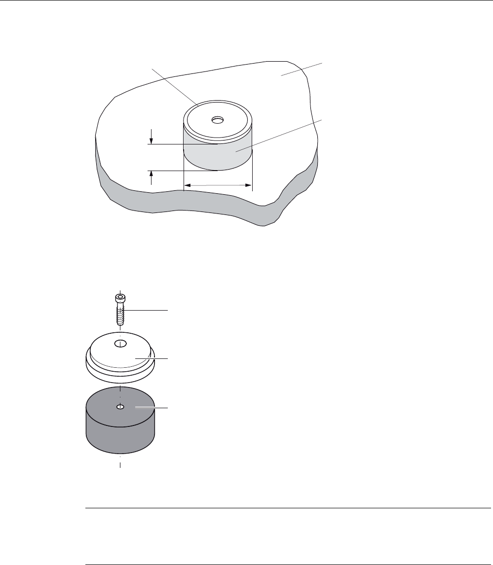
7.5.3 Mounting on metal
CAUTION
Damage to the MDS due to improper mounting
For mounting with the spacer (6GT2690-0AA00), use a stainless steel M5 screw to avoid
damaging the MDS in high temperatures (expansion coefficients).
In higher temperatures (> +80 °C), observe the expansion coefficients of all materials in
order to prevent damage to the MDS due to fastening.
ISO transponder
7.5 MDS D139
SIMATIC RF300
System Manual, 11/2009 - Zwischenstand 17.09.2009, A5E01642529-04 183
KุPP
)OXVKPRXQWLQJRIWKH0'6LQPHWDOLVQRWSHUPLWWHG
0RXQWLQJRQPHWDO
'DWDVWRUDJH
XQLW
6SDFHU
0HWDO
PP
Figure 7-10 Metal-free area for MDS D139
0RXQWLQJVFUHZ
6SDFHU
0'6'
Figure 7-11 MDS D139: Mounting recommended with spacer
Note
If the minimum guide values (h) are not observed, a reduction of the field data results. It is
possible to mount the MDS with metal screws (M5). This has no tangible impact on the
range. It is recommended that a test is performed in critical applications.

ISO transponder
7.5 MDS D139
SIMATIC RF300
184 System Manual, 11/2009 - Zwischenstand 17.09.2009, A5E01642529-04
7.5.4 Technical specifications
Table 7- 8 Technical data for MDS D139
Memory size 128 bytes
Memory configuration
Serial number
Configuration memory
Application memory
8 bytes (fixed code)
8 bytes
112 bytes
Storage technology EEPROM
Memory organization See MOBY D System Manual,
Chapter 5.1, "Mobile Data Storage Units, Introduction",
section "Memory Allocation"
Data retention 10 years
MTBF 2 x 10⁶ hours
Read cycles Unlimited
Write cycles at +40 °C
minimum
typical
100 000
1.000.000
Read/write distance (Sg) See Chapter Field data of ISO transponders (Page 44).
Distance from metal min. 30 mm (approx. 30% reduction of the field data)
Multitag capability Yes
Power supply Inductive power transmission
(without battery)
Degree of protection to EN 60529 IP68/x9K
Shock according to EN 60721-3-7, Class
7M3
Total shock response spectrum, Type II
50 g
Vibration-resistant to EN 60721-3-7, Class
7M3
20 g
Torsion and bending load Not permissible
Dimensions (D x H) in mm 85 x 15
Color Black
Material Plastic PPS
No silicone
Fixing 1 x M5 screw 1)
Tightening torque 1.5 Nm 2)
-25 °C to +100 °C Permanent
+120 °C to +140 °C 20% reduction in the limit
distance
+200 °C 3) Tested up to 5000 hours or
3000 cycles
Ambient temperature During
operation
+220 °C Tested up to 2000 hours or
1500 cycles
ISO transponder
7.5 MDS D139
SIMATIC RF300
System Manual, 11/2009 - Zwischenstand 17.09.2009, A5E01642529-04 185
Transport
and storage -40 °C to +100 °C
Weight Approx. 50 g
1) For mounting with the spacer (6GT2690-0AA00), use a stainless steel M5 screw to avoid
damaging the MDS in high temperatures (expansion coefficient).
2) In higher temperatures (> +80 °C), observe the expansion coefficient of all materials in order to
prevent damage to the MDS due to fastening.
3) Note that no processing is possible at temperatures of +140 °C or higher.
7.5.5 Use of the MDS D139 in hazardous areas
The MDS D139 mobile data memory is classed as a piece of simple, electrical equipment
and can be operated in Protection Zone 2, Device Group II, Category 3G.
The following requirements of the Directive 94/9/EC are fulfilled:
II 3 G Ex nA II T2 EN 60079-0 :2006 and EN 60079-15 : 2005
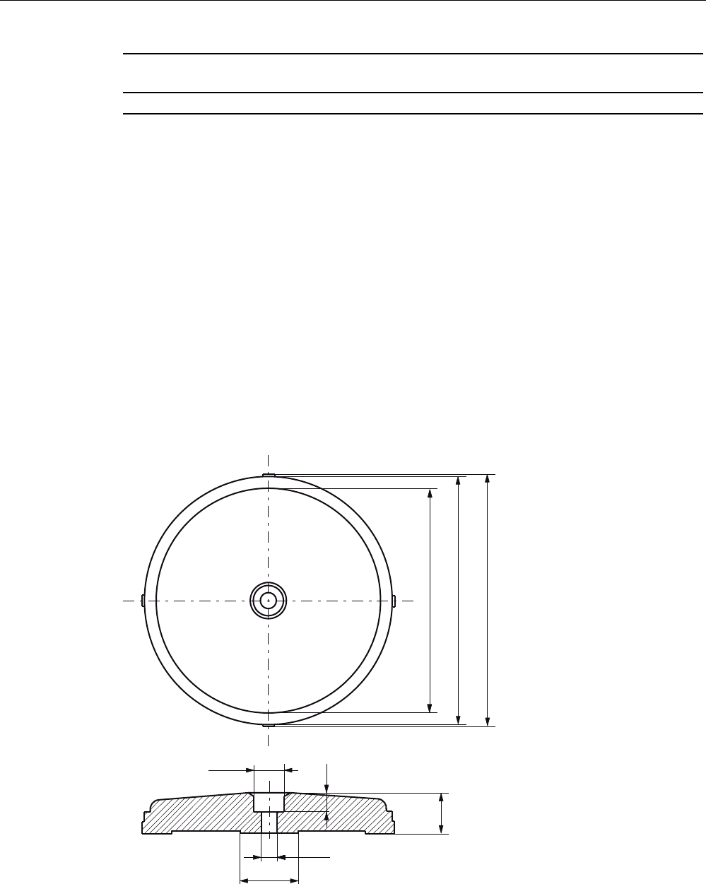
7.5.6 Dimensional drawing
Dimensions in mm
Figure 7-12 Dimensional drawing MDS D139
ISO transponder
7.6 MDS D160
SIMATIC RF300
186 System Manual, 11/2009 - Zwischenstand 17.09.2009, A5E01642529-04
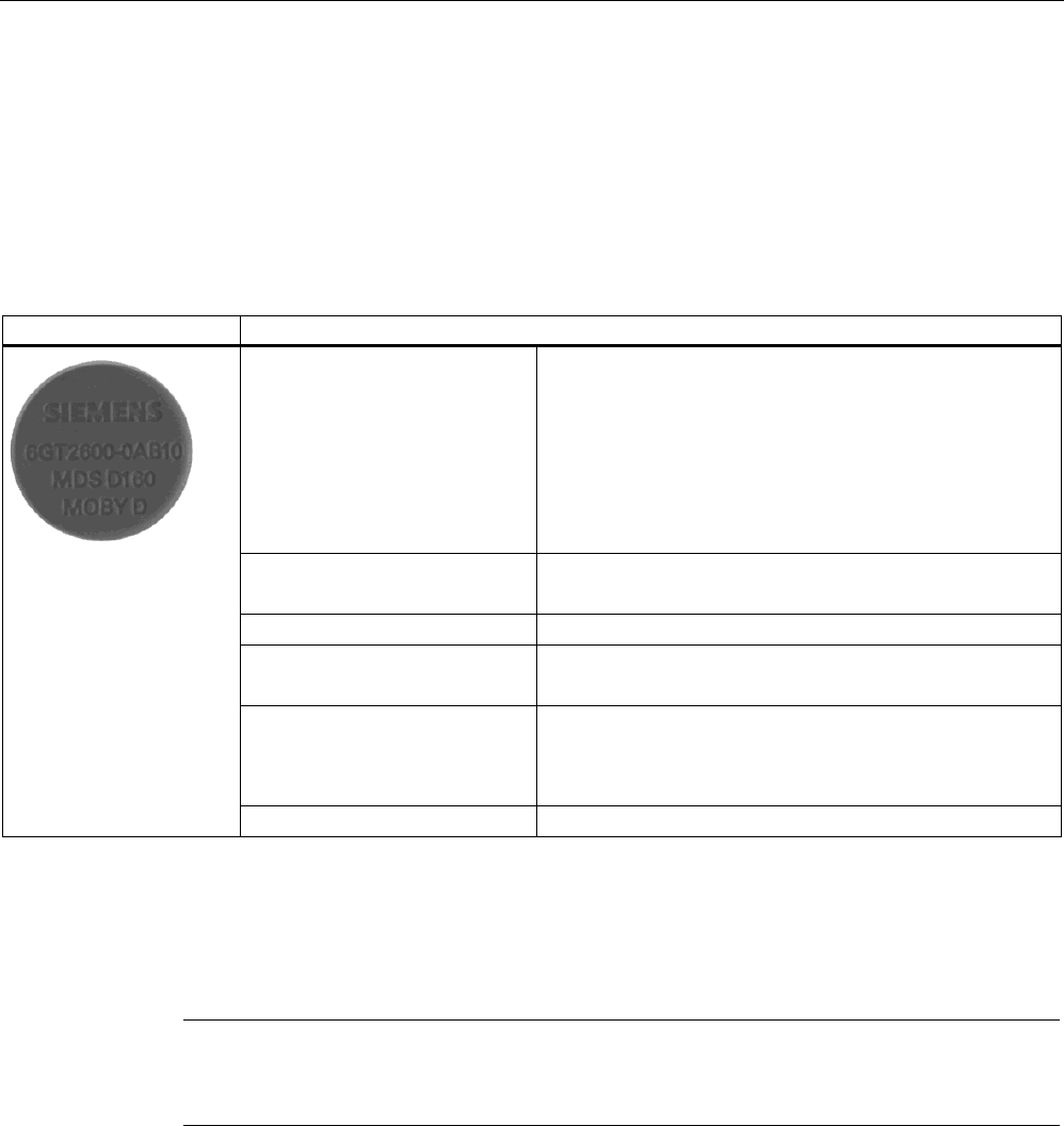
7.6 MDS D160
7.6.1 Characteristics
This mobile data memory is a passive, maintenance-free laundry tag based on the ISO
15693 standard with I-Code technology for cyclic applications.
MDS D160 Characteristics
Field of application Typical applications are, for example:
Rented work clothing
Hotel laundry
Surgical textiles
Hospital clothing
Dirt collection mats
Clothing for nursing homes/hostels
Memory EEPROM 128 bytes gross
112 bytes net capacity
Read/write range See Chapter Field data of ISO transponders (Page 44).
Mounting on metal Not possible:
Recommended distance from metal ≥ 25 mm
High resistance Thanks to its rugged packaging, the MDS D160 is a
transponder that can be used under extreme environmental
conditions. It is washable, heat-resistant and resistant to all
chemicals generally used in the laundry process.
ISO standard 15693 with I-code technology for cyclic applications
7.6.2 Information for RF300 compatibility
Note
Compatibility with SIMATIC RF300 depending on MLFB number
Only the MDS D160 with MLFB 6GT2600-0AB10 is compatible with SIMATIC RF300.
ISO transponder
7.6 MDS D160
SIMATIC RF300
System Manual, 11/2009 - Zwischenstand 17.09.2009, A5E01642529-04 187
7.6.3 Ordering data
Table 7- 9 Ordering data for MDS D160
MDS D160 Order number
IP68 (24 hours, 2 m, +20 °C)
Memory size: 112 byte user memory
Operating temperature: -25 °C ... +70 °C
Dimensions: 16 x 3 ±0.1 (Ø x H in mm)
Laundry tag for cyclical applications (r/w)
6GT2600-0AB10
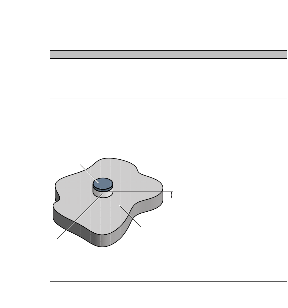
7.6.4 Mounting on metal
Mounting on metal
1RQPHWDO
0HWDO
'DWDPHPRU\
K
h ≥ 25 mm
Figure 7-13 Mounting of the MDS D160 on metal with spacer
Note
If the minimum guide values (h) are not observed, a reduction of the field data results.
In critical applications, it is recommended that a test is performed.
Flush-mounting
Flush-mounting of the MDS D160 in metal is not permitted!

ISO transponder
7.6 MDS D160
SIMATIC RF300
188 System Manual, 11/2009 - Zwischenstand 17.09.2009, A5E01642529-04
7.6.5 Technical specifications
Memory size 128 bytes
Memory configuration
Serial number
Configuration memory
Application memory
8 bytes (fixed code)
8 bytes
112 bytes
Storage technology EEPROM
Memory organization EEPROM 128 bytes gross
112 bytes net capacity
When using the OPT area, 16 bytes of it must be
subtracted in 4 byte blocks
Protocol According to ISO 15693
Data retention (at +55 °C) 10 years
MTBF (at +40 °C) 2x 10 6 hours
Data transmission rate
Read
Write
Approx. 3.5 ms/byte
Approx. 9.5 ms/byte
Bulk detection/multitag capability Yes
Data retention 10 years
Read cycles Unlimited
Write cycles at + 40 °C, typical 1 000 000
Write cycles, min. 100 000
Read/write distance (Sg) See Chapter Field data of ISO transponders
(Page 44)
Distance from metal Min. 25 mm (approx. 30% reduction of the field
data)
Power supply Inductive power transmission
(without battery)
Degree of protection to EN 60529 IP68 (24 hours, 2 m, +20 °C)
Shock, tested in accordance with IEC 68-2-27 40 g
(18 ms; 6 axes; 2000 repeats/h)
Vibration, tested in accordance with IEC 68-2-6 10 g
(10 to 2000 Hz; 3 axes; 2.5 h)
Torsion and bending load Not permissible
Mechanical strength
Isostatic pressure
Axial pressure
Radial pressure
300 bar for 5 min
1000 N for 10 s
1000 N for 10 s
Resistance to chemicals All chemicals normally used in the washing
process
MDS lifespan At least 100 wash cycles
ISO transponder
7.6 MDS D160
SIMATIC RF300
System Manual, 11/2009 - Zwischenstand 17.09.2009, A5E01642529-04 189
Mechanical design
Color
Material
Dimensions (D x H) in mm
Pressed, impact-resistant plastic
Gray
PPA (polyphthalamide)
16 x 3 ±0.1
MDS fixing Patch, sew, glue
-25 °C to
+70 °C
Permanent
+120 °C
for 100 hours
(20% reduction in the limit
distance)
+175 °C 100 x for 10 minutes
During operation
+220 °C 1 x for 30 seconds
Ambient temperature
Transport and
storage
-25 °C to +85 °C
Weight, approx. 1 g
* No processing possible from +140 °C upwards @ wo gehört diese Fußnote hin?
Note
Regeneration time for the MDS D160 between wash cycles must be at least 24 hours
It is recommended that a test is performed in critical applications.
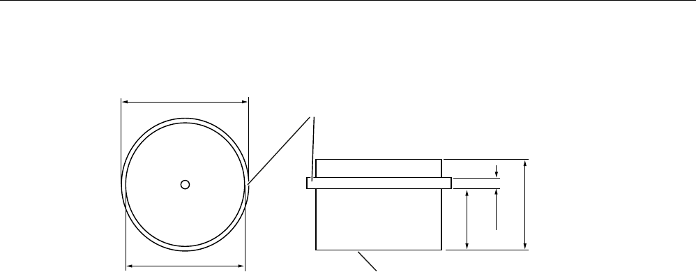
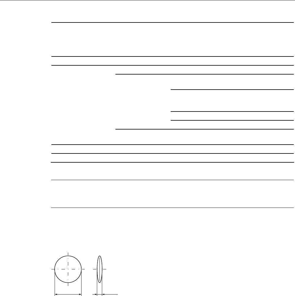
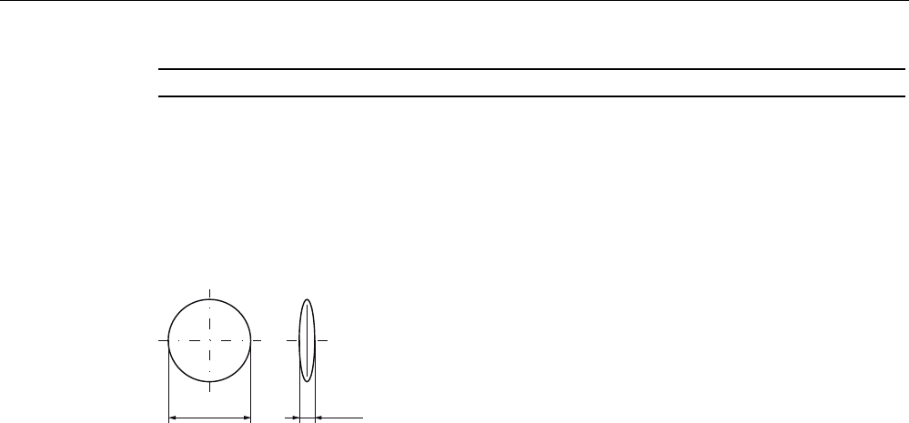
7.6.6 Dimension drawing
Dimensions in mm
Figure 7-14 Dimension drawing of MDS D160

ISO transponder
7.7 MDS D324
SIMATIC RF300
190 System Manual, 11/2009 - Zwischenstand 17.09.2009, A5E01642529-04
7.7 MDS D324
7.7.1 Characteristics
The MDS D324 is a passive, maintenance-free transponder based on the ISO standard
15693 with my-d technology.
MDS D324 Characteristics
Field of application Production and distribution logistics
and product identification
Memory For the user, the usable application
memory amounts to 992 byte.
Read/write range See Chapter Field data of ISO
transponders (Page 44).
Mounting on metal Not possible:
Recommended distance from metal
≥ 25 mm
High resistance Can also be used in harsh
environments under extreme
environmental conditions (e.g. with
higher temperature load).
ISO standard 15693 with my-d technology.
7.7.2 Ordering data
Table 7- 10 Ordering data MDS D324
MDS D324 Order number
IP67
Memory size: 992 byte EEPROM user memory
Operating temperature: -25 °C...+125 °C
Dimensions: 27 x 4 (Ø x H in mm)
6GT2600-3AC00
ISO transponder
7.7 MDS D324
SIMATIC RF300
System Manual, 11/2009 - Zwischenstand 17.09.2009, A5E01642529-04 191
7.7.3 Mounting on metal
Mounting on metal
1RQPHWDO
0HWDO
'DWDPHPRU\
K
h ≥ 25 mm
Figure 7-15 Mounting of the MDS D324 on metal with spacer
D
'DWDPHPRU\ 0HWDO
1RQPHWDO
K
h ≥ 25 mm
a ≥ 25 mm
Figure 7-16 Flush-mounting of MDS D324 in metal with spacer
Note
If the minimum guide values (h) are not observed, a reduction of the field data results. It is
possible to mount the MDS with metal screws (M3 countersunk head screws). This has no
tangible impact on the range.

ISO transponder
7.7 MDS D324
SIMATIC RF300
192 System Manual, 11/2009 - Zwischenstand 17.09.2009, A5E01642529-04
7.7.4 Technical specifications
Table 7- 11 Technical data MDS D324
Memory size 1024 bytes
Memory configuration
Serial number
Configuration memory
Manufacturer data
8 bytes (fixed code)
1008 bytes
8 bytes
Storage technology EEPROM
Memory organization 1024 EEPROM/gross
992 net capacity
When using the OPT area, 16 bytes of it must be
subtracted in 4 byte blocks
Protocol according to ISO 15693
Data retention (at +40 °C) 10 years
MTBF (at +40 °C) ≥ 1.5 x 10⁶ hours
Data transmission rate
Read
Write
Approx. 3.5 ms/byte
Approx. 9.5 ms/byte
Read cycles Unlimited
Write cycles, typical 1 000 000
Write cycles, min. 100 000
Read/write distance (Sg) See Chapter Field data of ISO transponders
(Page 44)
Distance from metal Min. 25 mm (approx. 30% reduction of the field data)
Multitag capability Yes
Anti-collision speed Approx. 20 transponders/s simultaneously
identifiable
Power supply Inductive power transmission
(without battery)
Degree of protection to EN 60529 IP67
Shock resistant to EN 60721-3-7, Class 7M3
total shock response spectrum, type II
100 g
Vibration-resistant to EN 60721-3-7, Class
7M3
20 g
Torsion and bending load Not permissible
Dimensions (D x H) in mm 27 x 4
Color Black
Material Epoxy casting resin
Fixing Adhesive, M3 screw
Tightening torque at +20 °C ≤ 1 Nm
(at high temperatures, the expansion coefficients of
the materials used must be taken into account)
ISO transponder
7.8 MDS D421
SIMATIC RF300
System Manual, 11/2009 - Zwischenstand 17.09.2009, A5E01642529-04 193
Ambient temperature
During operation
Transport and storage
-25 °C to +125 °C
-40 °C to +150 °C
Weight, approx. 5 g
7.7.5 Dimension drawing
s
s
Dimensions in mm
Figure 7-17 Dimension drawing of MDS D324
7.8 MDS D421
7.8.1 Characteristics
MDS D421 Characteristics
Field of application The MDS D421 is designed for tool coding in accordance
with DIN 69873.
It can be used wherever small data carriers and exact
positioning are required, e.g. tool identification, workpiece
holders
Memory FRAM 2048 bytes gross
2000 bytes net
Read/write range See Chapter .
Mounting Flush-mounted in and on metal
High resistance Rugged packaging of the MDS D421; can therefore also be
used in a harsh industrial environment without problem
Standard Oriented according to ISO standard 15693
ISO transponder
7.8 MDS D421
SIMATIC RF300
194 System Manual, 11/2009 - Zwischenstand 17.09.2009, A5E01642529-04
7.8.2 Ordering data
Table 7- 12 Ordering data of MDS D421
MDS D421 Order number
Memory size: 2000 byte FRAM user memory
Operating temperature: –25 °C to +85 °C
Dimensions: 10 x 4.5 (Ø x H in mm)
IP 67 / x9K
6GT2600-4AE00
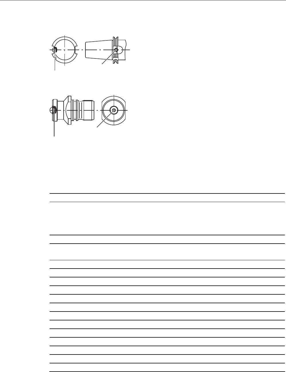
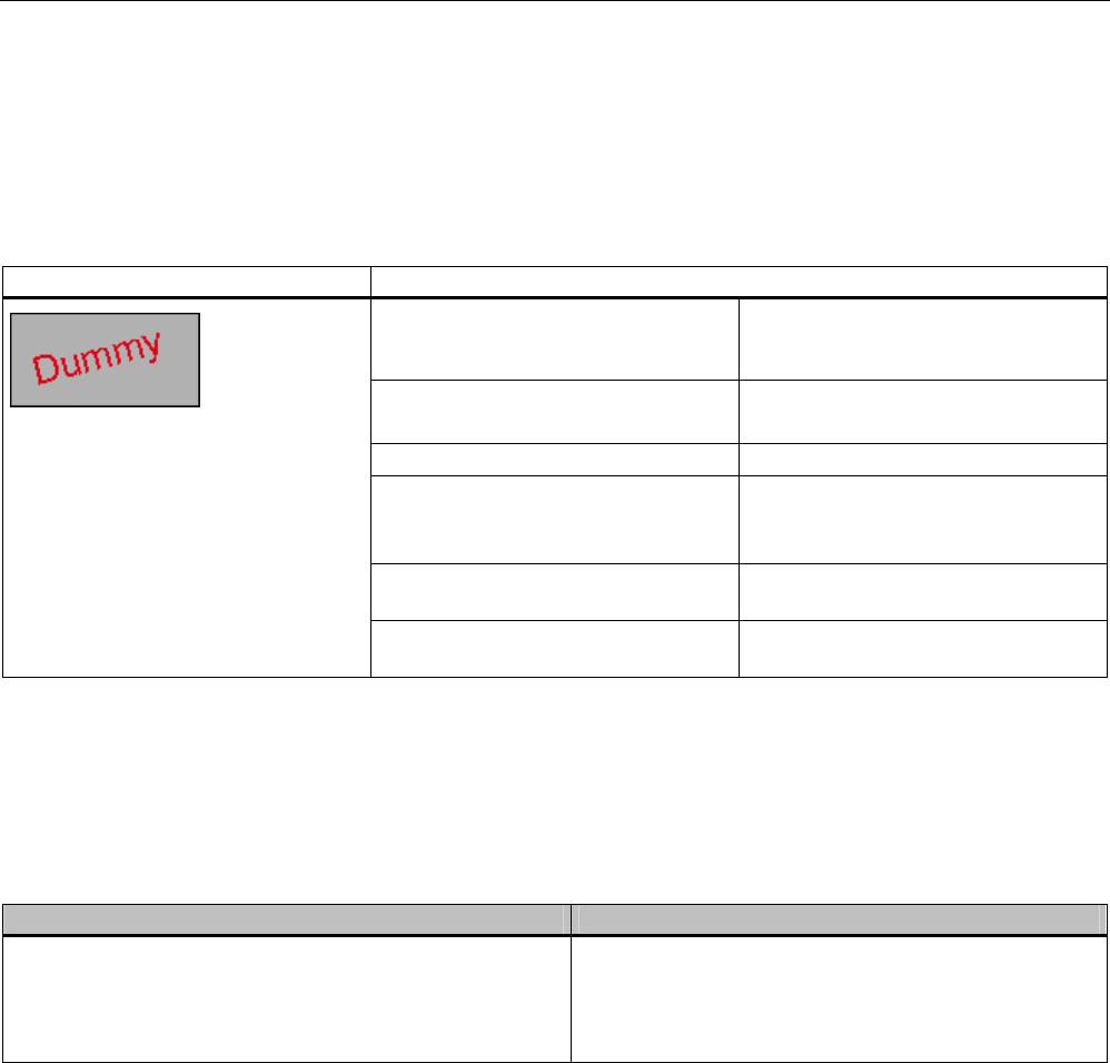
7.8.3 Mounting on metal
Mounting on metal
'DWDPHPRU\
0HWDO
0'6'
SIEMENS
Figure 7-18 Mounting of MDS D421 on metal
Flush-mounting
'DWDPHPRU\
0HWDO
0'6'
SIEMENS
Figure 7-19 Mounting of MDS D421 in metal
ISO transponder
7.8 MDS D421
SIMATIC RF300
System Manual, 11/2009 - Zwischenstand 17.09.2009, A5E01642529-04 195
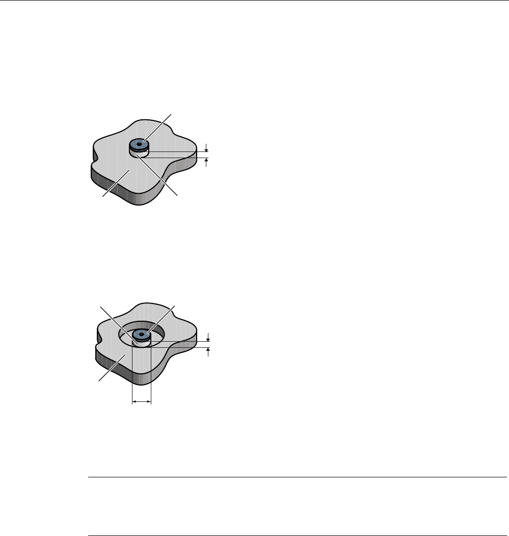
Flush-mounting of MDS D421 in metal with tools
0HWDO
$
QWHQQDHQG
DFWLYHVXUIDFH
E
0'6'
W
G
G
E
W
Figure 7-20 Flush-mounting of MDS D421 in metal with tools
b1 0.5 x 45° b2 0.3 x 45° or R 0.3
d1 10 (-0,04.. -0,13) d2 10 (+0,09... 0)
t1 4,5 (-0... -0,1) t2 4,6 (+0,2... 0)
Note
The MDS should not protrude out of the locating hole; it must be flush with the outside
contour.
The mounting instructions of the MDS and the conditions associated with the application
(e.g. peripheral speed, temperature, and use of coolant) must be observed during the
installation.
Mounting information for adhesion
● Drill installation hole
● The adhesive surfaces must be dry, free from dust, oil, stripping agents and other
impurities
● Apply adhesive according to the manufacturer's processing instructions
● Press in MDS D421 using your finger; antenna side to the outside (see figure "Flush-
mounting of MDS D421 in metal with tools")
● Remove residues of adhesive
● Allow to cure according to the manufacturer's instructions
● Flush-mounting of MDS D421 in metal with tools
ISO transponder
7.8 MDS D421
SIMATIC RF300
196 System Manual, 11/2009 - Zwischenstand 17.09.2009, A5E01642529-04
Installation examples
0'6
0'6
Figure 7-21 Installation example of MDS D421 in a steep cone
0'6
0'6
Figure 7-22 Installation example of MDS D421 in a stud bolt
7.8.4 Technical specifications
Memory size 2048 bytes
Memory configuration
Serial number
Configuration memory
Application memory
8 bytes (fixed code)
40 bytes
2000 bytes
Storage technology FRAM
Memory organization 2048 bytes gross
2000 bytes net
Protocol ISO 15693
MTBF (at +40 °C) 2.5 x 10⁶ hours
Read cycles Unlimited
Write cycles at +40 °C > 1010 typ.
Data transmission rate for read and write Approx. 2 ms/byte
Bulk detection/multitag capability Yes
Data retention (at +40°C) 10 years
Read/write distance (Sg) See Chapter
Direction-dependent No
Power supply Inductive power transmission (without battery)
1) Vibration in accordance with IEC 68-2-6 20 g
1) Shock in accordance with IEC 68-2-27 100 g
Torsion and bending load Not permissible
ISO transponder
7.8 MDS D421
SIMATIC RF300
System Manual, 11/2009 - Zwischenstand 17.09.2009, A5E01642529-04 197
MDS fixing Adhesion 2);
e.g. Araldit AW2101/HW2951 or 2021;
UHU-Plus endfest 300
Degree of protection
In accordance with EN 60529
In accordance with DIN 40050 Part 9
IP 67
IPx9K 3)
Enclosure
Color
Material
Dimensions (D x H) in mm
(dimensions and tolerances in accordance
with DIN 69873)
Pressed, impact-resistant plastic
Black
Epoxy casting resin
∅ 10 x 4.5
(chamfer underneath 0.5 x 45°)
During operation –25 °C to +85 °C Ambient temperature
Transport and storage –40 °C to +100 °C
Weight, approx. 4 g
1) The values for shock and vibration are maximum values and must not be applied continuously.
2) The manufacturer's processing instructions must be observed.
3) steam jet: 150 mm; 10 to 15 l/min; 100 bar; 75 °C
7.8.5 Dimension drawing
ෘ
2[r
Dimensions in mm
Figure 7-23 Dimension drawing of MDS D421
ISO transponder
7.9 MDS D424
SIMATIC RF300
198 System Manual, 11/2009 - Zwischenstand 17.09.2009, A5E01642529-04
7.9 MDS D424
7.9.1 Characteristics
MDS D424 Characteristics
Field of application Production and distribution logistics as
well as in assembly and production
lines
Memory FRAM 2048 bytes gross
2000 bytes net
Read/write range See Chapter .
Mounting on metal Not possible:
Recommended distance from metal
≥ 25 mm
High resistance Can also be used in a harsh industrial
environment without problem
Standard Oriented according to ISO standard
15693
7.9.2 Ordering data
Table 7- 13 Ordering data of MDS D424
MDS D424 Order number
Memory size: 992 byte EEPROM user memory
Operating temperature: -25 °C ...+125 °C
Dimensions: 27 x 4 (Ø x H in mm)
IP67
6GT2600-4AC00
ISO transponder
7.9 MDS D424
SIMATIC RF300
System Manual, 11/2009 - Zwischenstand 17.09.2009, A5E01642529-04 199
7.9.3 Mounting on metal
Mounting on metal
0HWDO
'DWDPHPRU\
1RQPHWDO
K
h ≥ 25 mm
Figure 7-24 Mounting of the MDS D424 on metal with spacer
Flush-mounting
0HWDO
1RQPHWDO 'DWDPHPRU\
K
D
h ≥ 25 mm
a ≥ 25 mm
Figure 7-25 Flush-mounting of MDS D424 in metal with spacer
Note
If the minimum guide values (h) are not observed, a reduction of the field data results. It is
possible to mount the MDS with metal screws (M3 countersunk head screws). This has no
tangible impact on the range.

ISO transponder
7.9 MDS D424
SIMATIC RF300
200 System Manual, 11/2009 - Zwischenstand 17.09.2009, A5E01642529-04
7.9.4 Technical specifications
Table 7- 14 Technical data of MDS D424
Memory size 2048 bytes
Memory configuration
Serial number
Configuration memory
Manufacturer data
8 bytes (fixed code)
1008 bytes
2000 bytes
Storage technology FRAM
Memory organization 2048 bytes gross
2000 bytes net
When using the OPT area, 16 bytes of it must be
subtracted in 4 byte blocks
Protocol SO 15693
Data retention (at +40 °C) 10 years
MTBF (at +40 °C) ≥ 1.5 x 10⁶ hours
Data transmission rate for read and write Approx. 2 ms/byte
Read cycles Unlimited
Write cycles (at +40 °C) > 1010
Read/write distance (Sg) See Chapter
Distance from metal Min. 25 mm (approx. 30% reduction of the field data)
Multitag capability Yes
Power supply Inductive power transmission
(without battery)
Degree of protection to EN 60529 IP 67, IP x9K 2)
1) Shock in accordance with EN 60721-3-7
Class 7M3
Total shock response spectrum, Type II
100 g
1) Vibration in accordance with EN 60721-3-7
Class 7M3
20 g
Torsion and bending load Not permissible
Dimensions (D x H) in mm
Enclosure
Color
Material
Dimensions
Black
Epoxy casting resin
27 x 4
Fixing M3 screw, adhesive
Tightening torque at +20 °C ≤ 1 Nm
ISO transponder
7.10 MDS D428
SIMATIC RF300
System Manual, 11/2009 - Zwischenstand 17.09.2009, A5E01642529-04 201
Ambient temperature
During operation
Transport and storage
-25 °C to +85 °C
-40 °C to +100 °C
Weight, approx. 5 g
1) The values for shock and vibration are maximum values and must not be applied continuously.
2) steam jet: 150 mm; 10 to 15 l/min; 100 bar; 75 °C
7.9.5 Dimension drawing
s
s
Dimensions in mm
Figure 7-26 Dimension drawing of MDS D424
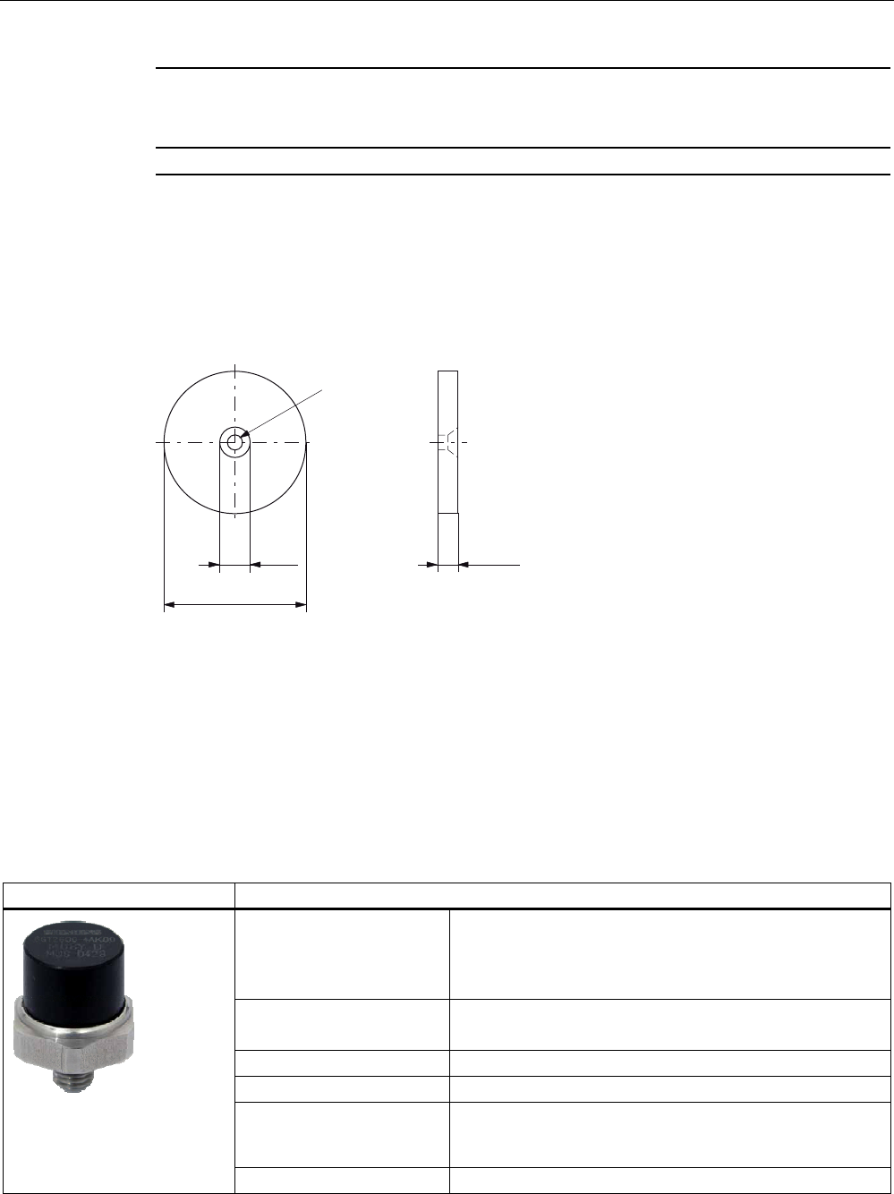
7.10 MDS D428
7.10.1 Characteristics
MDS D428 Characteristics
Field of application Compact and rugged ISO transponder; suitable for screw
mounting
Use in assembly and production lines in the powertrain
sector
Memory FRAM 2048 bytes gross
2000 bytes net
Read/write range See Chapter .
Mounting on metal Yes
High resistance Rugged packaging of the MDS D428; can therefore also be
used under extreme environmental conditions without
problem
Standard Oriented according to ISO-15693
ISO transponder
7.10 MDS D428
SIMATIC RF300
202 System Manual, 11/2009 - Zwischenstand 17.09.2009, A5E01642529-04
MDS D428 Characteristics
7.10.2 Ordering data
Table 7- 15 Ordering data of MDS D428
MDS D428 Order number
Memory size: 2000 byte FRAM user memory
Operating temperature: -25 °C ...+85 °C
Dimensions (D x H): 18 mm x 20 mm (without thread), tolerance 1 mm; M8
thread
IP68; IPx9K
6GT2600-4AK00
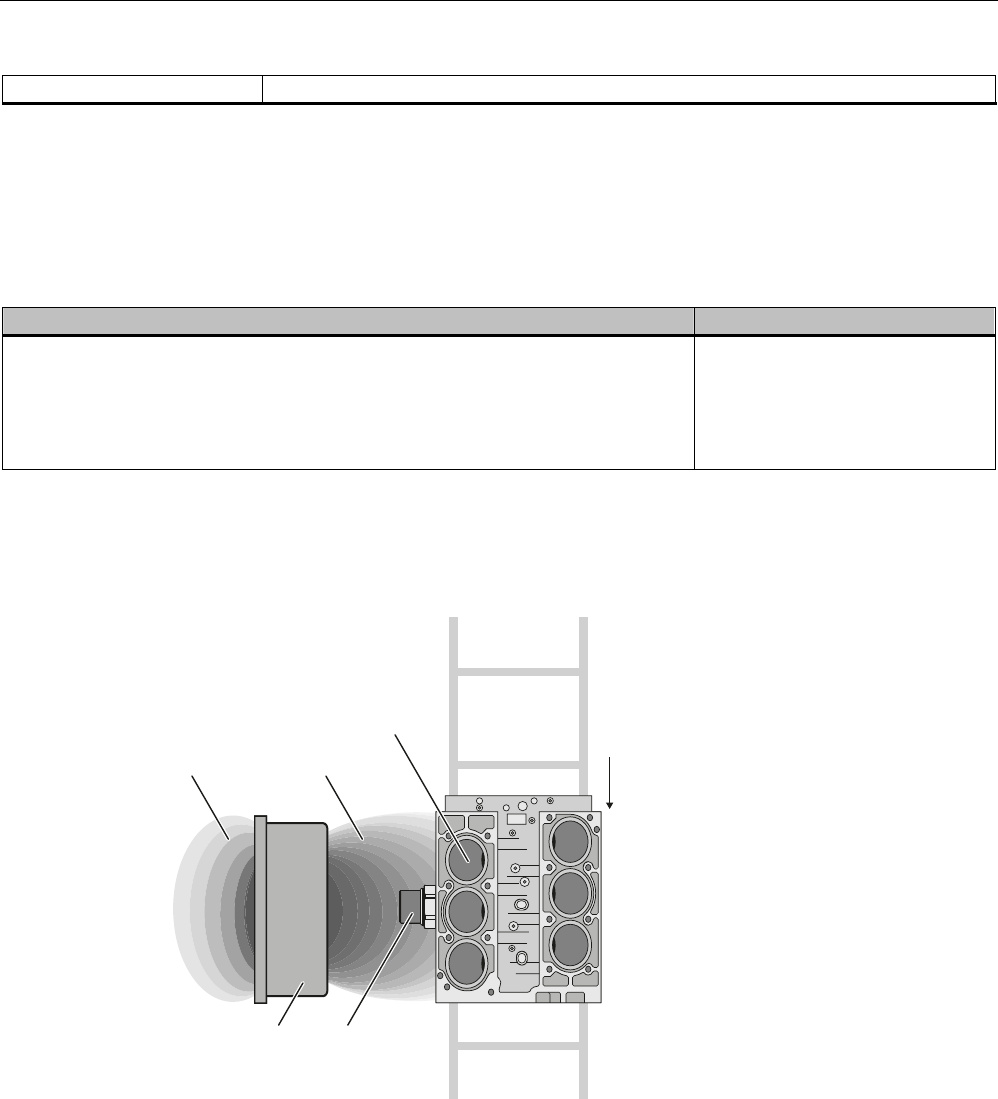
7.10.3 Application example of MDS D428
6HFRQGDU\ILHOG 0DLQILHOG
0RWRUEORFN
&RQYH\RUGLUHFWLRQ
0'6'6/*
Figure 7-27 Application example

ISO transponder
7.10 MDS D428
SIMATIC RF300
System Manual, 11/2009 - Zwischenstand 17.09.2009, A5E01642529-04 203
7.10.4 Technical specifications
Memory size 2048 bytes
Memory configuration
Serial number
Configuration memory
Application memory
8 bytes (fixed code)
40 bytes
2000 bytes
Storage technology FRAM
Memory organization 2048 bytes gross
2000 bytes net
Protocol ISO 15693
Data retention (at +40 °C) 10 years
Data transmission rate for read and write Approx. 2 ms/byte
Bulk detection/multitag capability Yes
Read cycles Unlimited
Write cycles at + 40 °C, typical > 1010
Read/write distance (Sg) See Chapter
Distance from metal Can be mounted on metal
Power supply Inductive power transmission
(without battery)
Degree of protection to EN 60529 IP68 1)
IPx9K 2)
3) Shock in accordance with IEC 68-2-27 50 g
3) Vibration in accordance with IEC 68-2-6 20 g
Torsion and bending load Not permissible
Enclosure
Color
Material
Dimensions (D x H)
Black
Plastic PA 6.6 GF;
thread: Stainless steel
18 mm x 20 mm (without thread), tolerance
1 mm; M8 thread
MDS fixing Screws, tightening torque (at room temperature) ≤
1 Nm
Ambient temperature
During operation
Transport and storage
-25 °C to +85 °C
-40 °C to + 125 °C
Weight, approx. 35 g
1) 24 hours, 2 m, +20 °C
2) steam jet: 150 mm; 10 to 15 l/min; 100 bar; 75 °C
3) The values for shock and vibration are maximum values and must not be applied continuously.
ISO transponder
7.11 MDS D460
SIMATIC RF300
204 System Manual, 11/2009 - Zwischenstand 17.09.2009, A5E01642529-04
Note
It is recommended that a test is performed in critical applications.
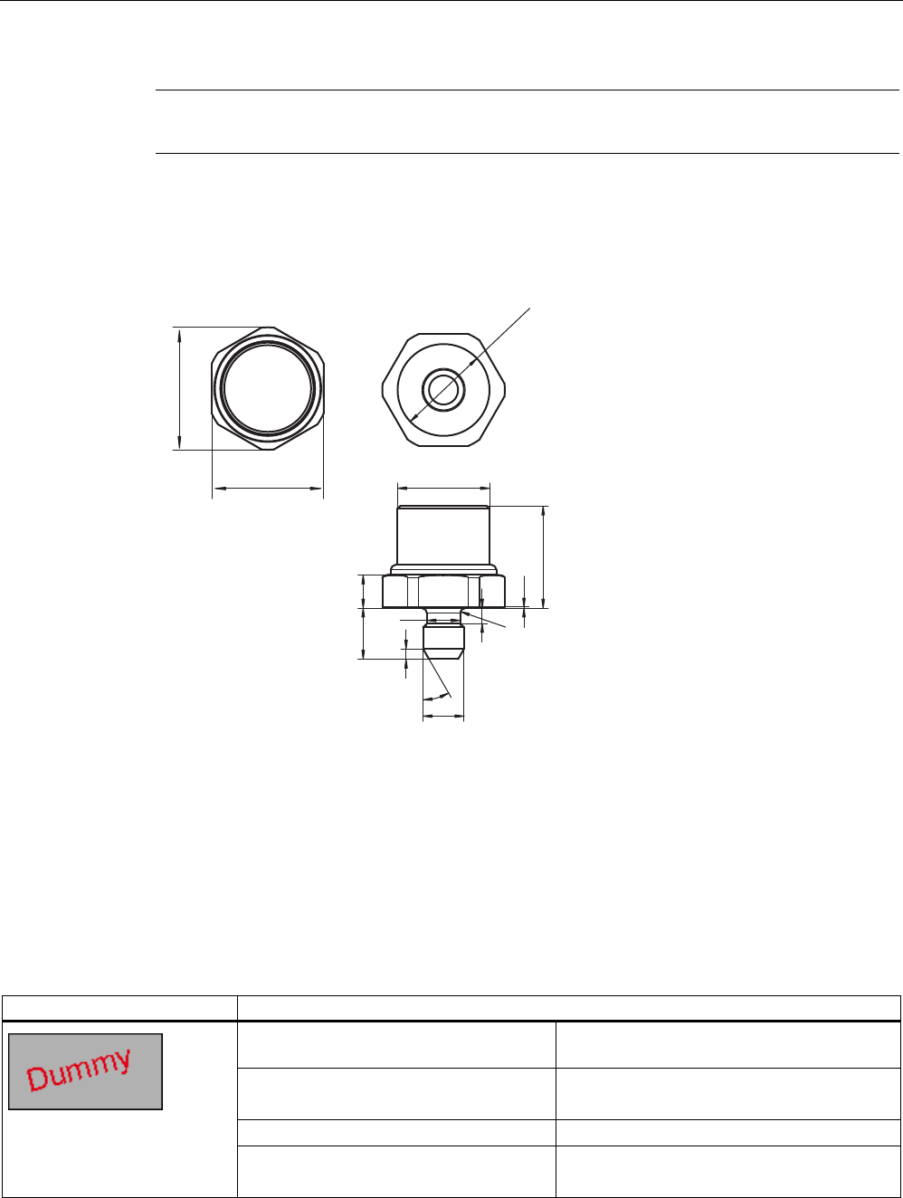
7.10.5 Dimension drawing
SIEMENS
*7$.
02%<'
0'6'
0
r
ෘ
5
ෘ
Dimensions in mm
Figure 7-28 Dimension drawing of MDS D428
7.11 MDS D460
7.11.1 Characteristics
MDS D460 Characteristics
Field of application Identification tasks on small assembly lines in
harsh industrial environments
Memory FRAM 2048 bytes gross
2000 bytes net
Read/write range See Chapter .
Mounting on metal Not possible:
Recommended distance from metal ≥ 25 mm
ISO transponder
7.11 MDS D460
SIMATIC RF300
System Manual, 11/2009 - Zwischenstand 17.09.2009, A5E01642529-04 205
MDS D460 Characteristics
High resistance Can also be used in a harsh industrial
environment
Standard Oriented according to ISO standard 15693
7.11.2 Ordering data
Table 7- 16 Ordering data of MDS D460
MDS D460 Order number
Memory size: 2000 byte FRAM user memory
Operating temperature: -25 °C ...+85 °C
Dimensions: 16 x 3 ±0.1 (Ø x H in mm)
IP68
6GT2600-4AB00
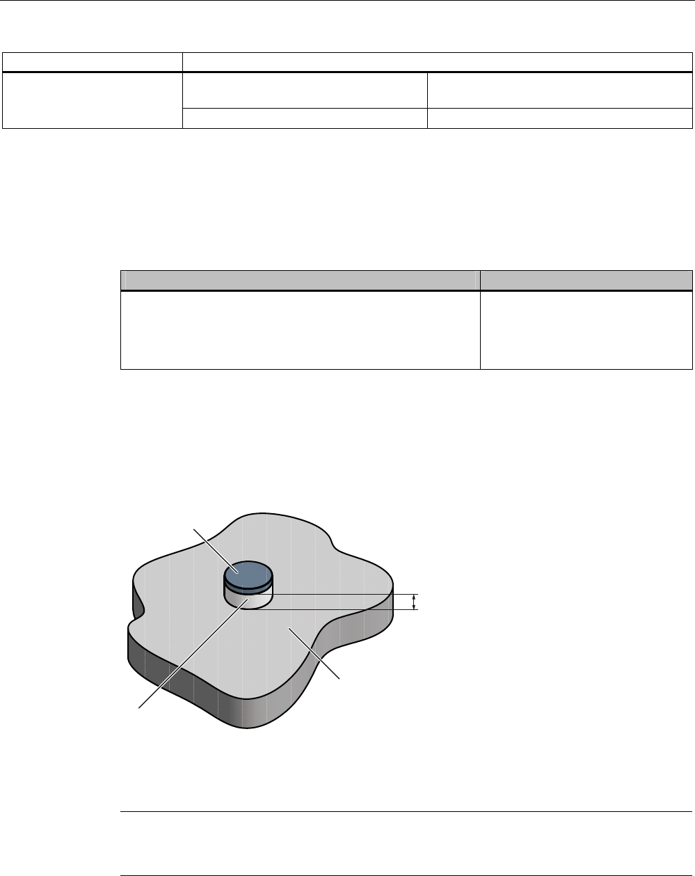
7.11.3 Mounting on metal
Mounting on metal
1RQPHWDO
0HWDO
'DWDPHPRU\
K
h ≥ 25 mm
Figure 7-29 Mounting of the MDS D460 on metal with spacer
Note
If the minimum guide values (h) are not observed, a reduction of the field data results.
In critical applications, it is recommended that a test is performed.

ISO transponder
7.11 MDS D460
SIMATIC RF300
206 System Manual, 11/2009 - Zwischenstand 17.09.2009, A5E01642529-04
Flush-mounting
Flush-mounting of the MDS D460 in metal is not permitted!
7.11.4 Technical specifications
Memory size 2048 bytes
Memory configuration
Serial number
Configuration memory
Application memory
8 bytes (fixed code)
40 bytes
2000 bytes
Storage technology FRAM
Memory organization 2048 bytes gross
2000 bytes net
Protocol ISO 15693
Data retention (at +40 °C) 10 years
MTBF (at +40 °C) 2 x 10⁶ hours
Data transmission rate for read and write Approx. 2 ms/byte
Bulk detection/multitag capability Yes
Read cycles Unlimited
Write cycles (at +40 °C, typical) > 1010
Read/write distance (Sg) See Chapter
Distance from metal min. 25 mm (approx. 30% reduction of the field
data)
Power supply Inductive power transmission
(without battery)
Degree of protection to EN 60529 IP68 1)
IPx9K 2)
3) Shock in accordance with IEC 68-2-27 50 g
3) Vibration in accordance with IEC 68-2-6 20 g
Torsion and bending load Not permissible
Mechanical design
Color
Material
Dimensions (D x H) in mm
Pressed, impact-resistant plastic
Black
Epoxy casting resin
16 x 3 ±0,2
MDS fixing Adhesion, spacer
During operation -25 °C to +85 °C permanent
Ambient temperature
Transport and
storage
-40 °C to +100 °C
ISO transponder
7.11 MDS D460
SIMATIC RF300
System Manual, 11/2009 - Zwischenstand 17.09.2009, A5E01642529-04 207
Weight, approx. 3 g
1) 2 hours, 2 m, +20 °C
2) steam jet: 150 mm; 10 to 15 l/min; 100 bar; 75 °C
3) The values for shock and vibration are maximum values and must not be applied continuously.
7.11.5 Dimension drawing
Dimensions in mm
Figure 7-30 Dimension drawing of MDS D460