Siemens RF340R01 Inductive Tag Reader User Manual SIMATIC RF300
Siemens AG Inductive Tag Reader SIMATIC RF300
UserManual.wiki
>
Siemens
>
RF340R01 User Manual
>
User Manual III
Contents
1.
User Manual I
2.
User Manual II
3.
User Manual III
4.
User Manual IV
User Manual III
Navigation menu
Upload a User Manual
Namespaces
Wiki Guide
HTML
PDF
Info
Views
User Manual
Discussion / Help
Navigation
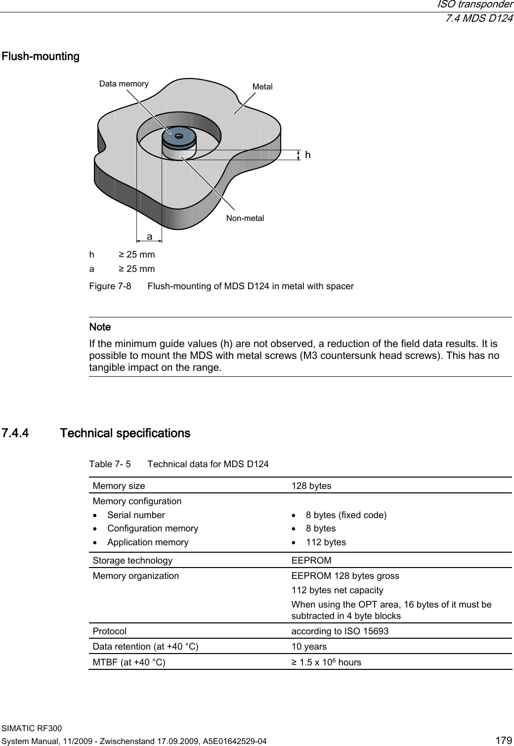
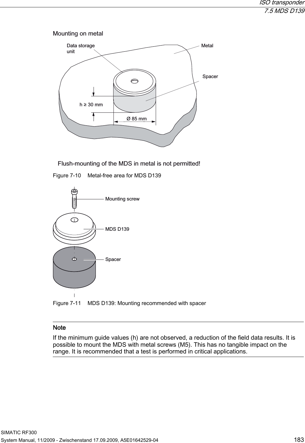
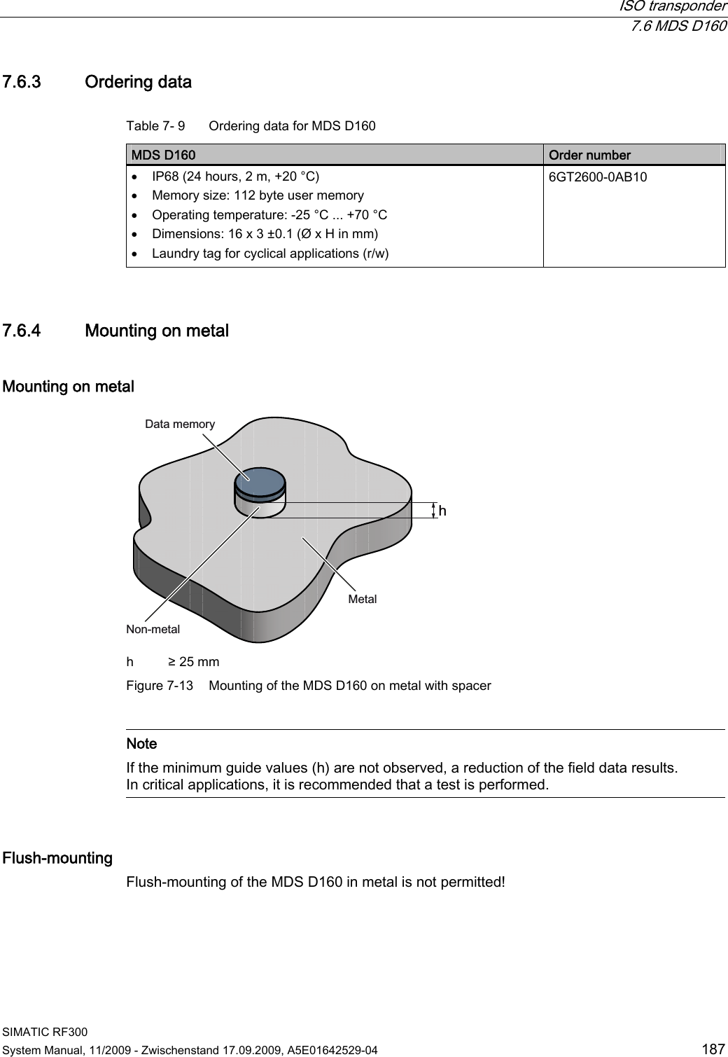
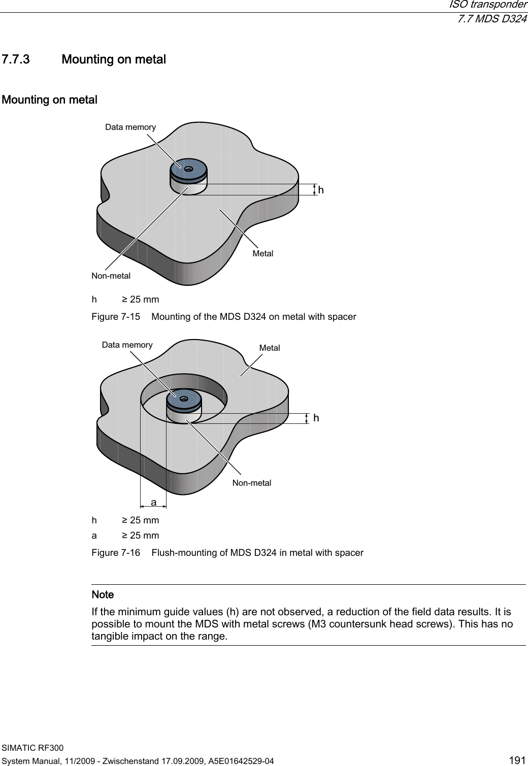
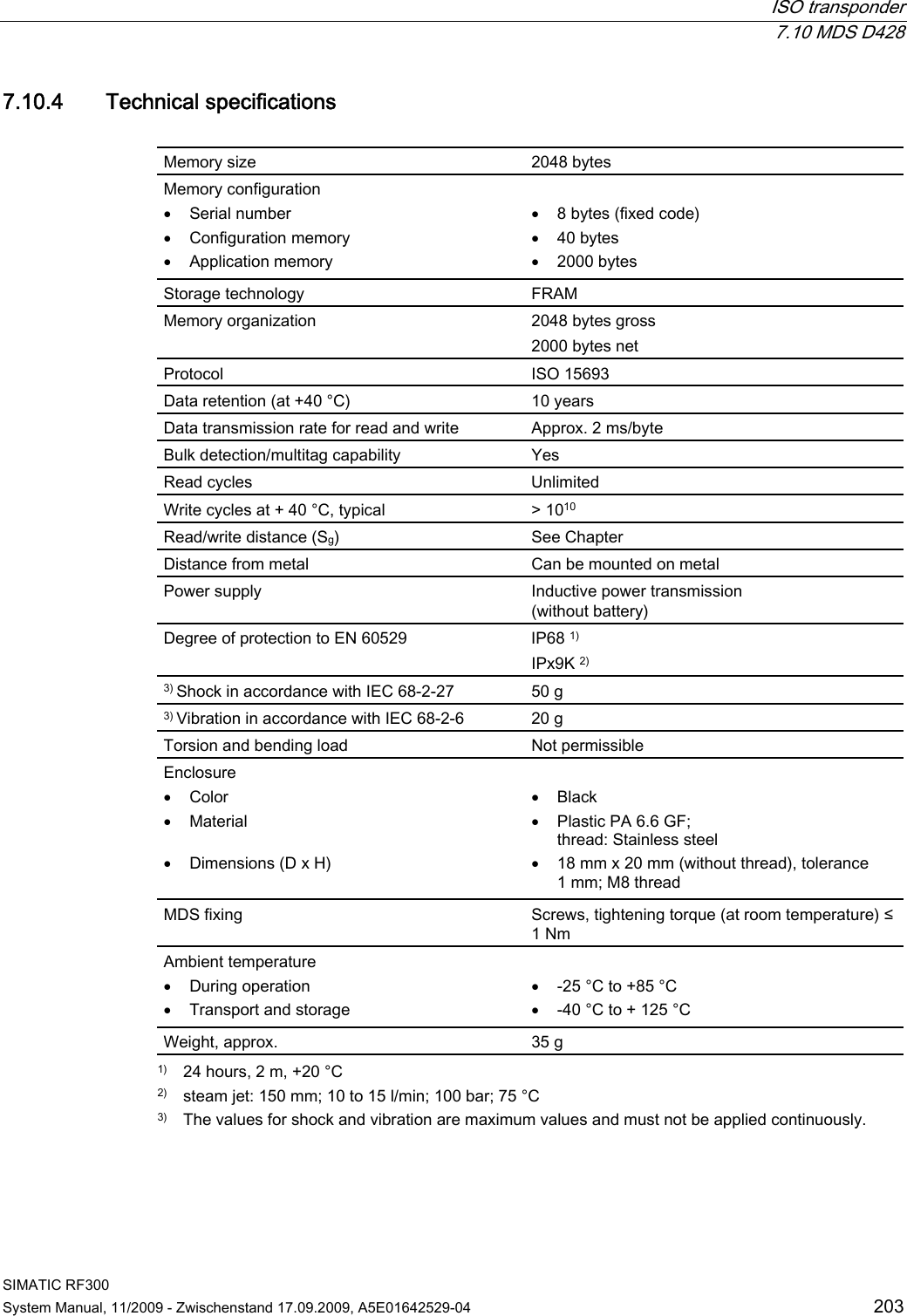
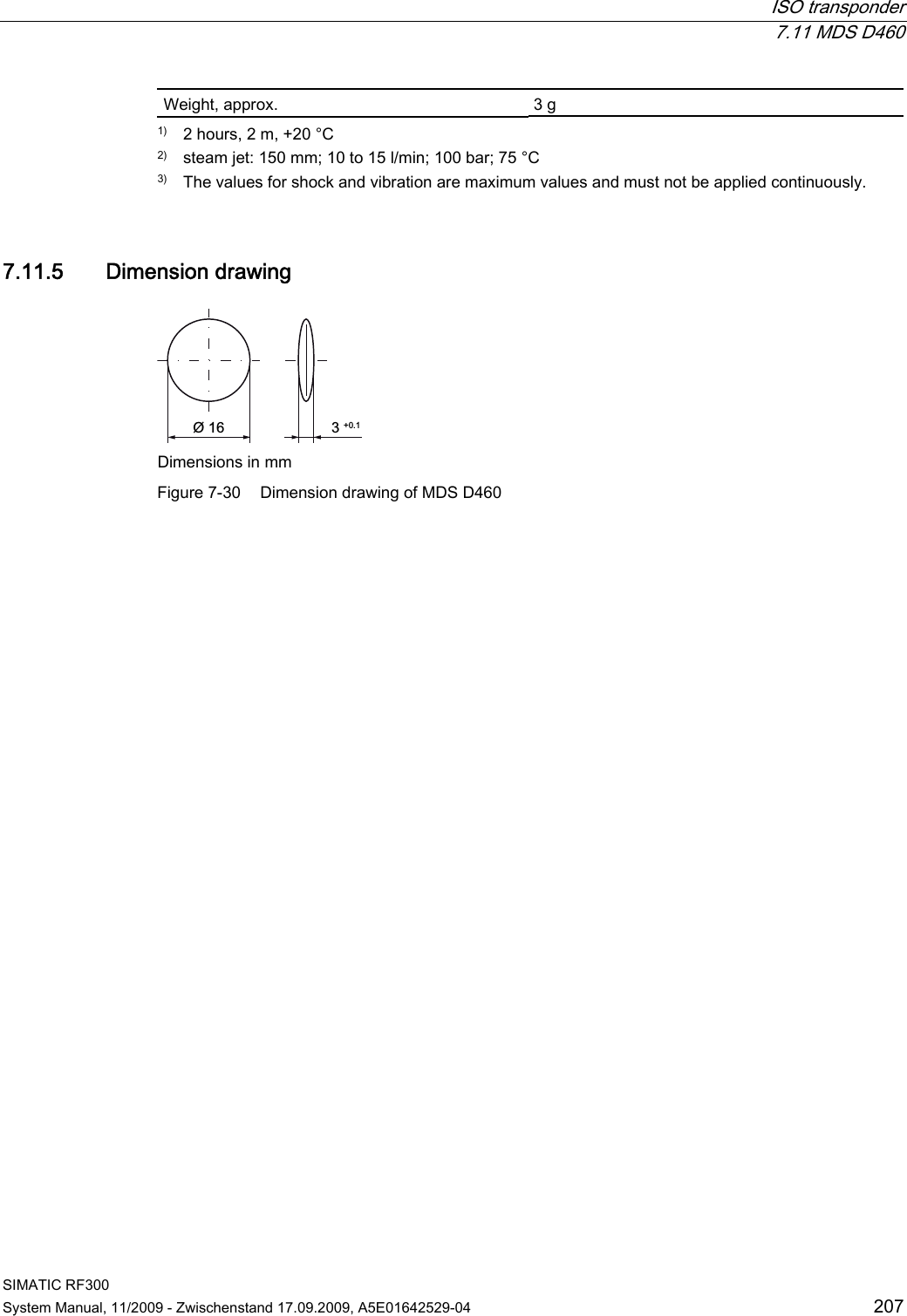
![RF300 transponder 6.6 SIMATIC RF360T SIMATIC RF300 150 System Manual, 11/2009 - Zwischenstand 17.09.2009, A5E01642529-04 6.6.4 Technical data Table 6- 9 Technical specifications for RF360T Memory size 8 KB Memory organization Blocks of 8 bits/byte-by-byte Memory configuration Serial number (UID) Application memory OTP 1) memory 4 bytes (fixed code) 8189 bytes r/w 20 bytes Storage technology FRAM / EEPROM MTBF (Mean Time Between Failures) in years 1200 Write cycles, at +40 °C Virtually unlimited (>1010) Read cycles Virtually unlimited (>1010) Data transmission time Read Write With RS422 reader: Approx. 0.13 ms/byte approx. 0.13 ms/byte With IQ-Sense reader: Approx. 20 ms/byte approx. 25 ms/byte Data retention > 10 years Read/write distance Dependent on the reader used [see Chapter Field data of RF300 transponders (Page 41)] Multitag capability max. 4 transponders Recommended spacing from metal ≥ 20 mm; e.g. using spacer 6GT2190-0AA00 in conjunction with fixing pocket 6GT2190-0AB00 Power supply Inductive, without battery Degree of protection to EN 60529 Shock to EN 60721-3-7 Vibration to EN 60721-3-7 Torsion and bending load IP67 50 g 20 g Not permitted permanently Enclosure dimensions Color Material Fixing 85.8 x 54.8 x 2.5 mm (L x W x H) Anthracite Epoxy resin 2 screws (M3) or with fixing pocket 6GT2190-0AB00 Ambient temperature Operation Transport and storage -25°C to +75°C -40°C to +85°C Weight Approx. 25 g 1) OTP: One Time Programmable](https://usermanual.wiki/Siemens/RF340R01.User-Manual-III/User-Guide-1196869-Page-1.png)
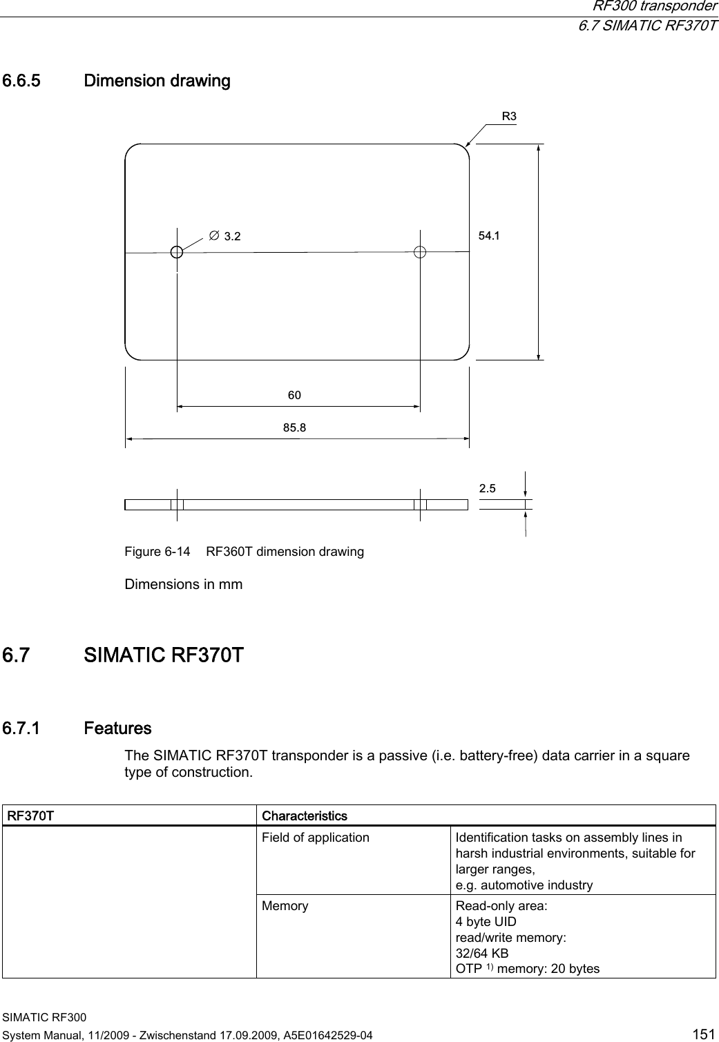
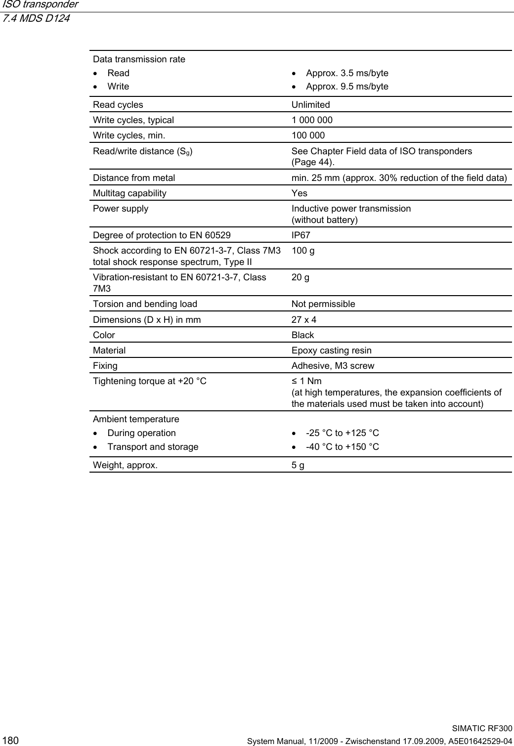
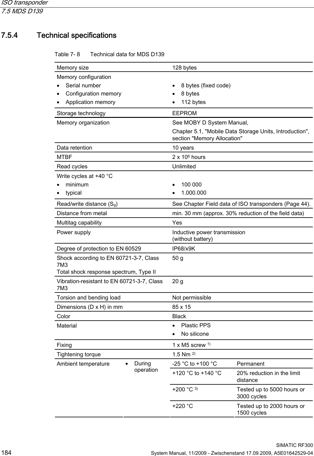
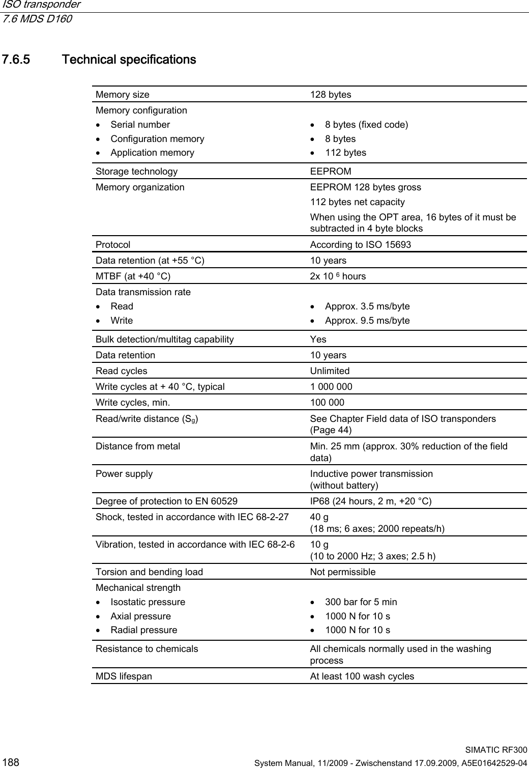
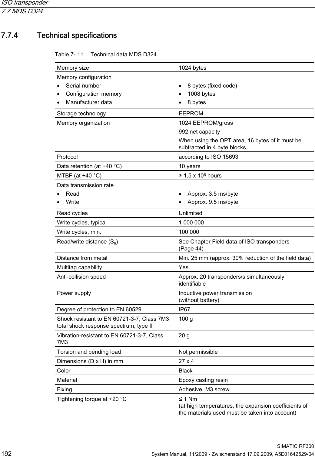
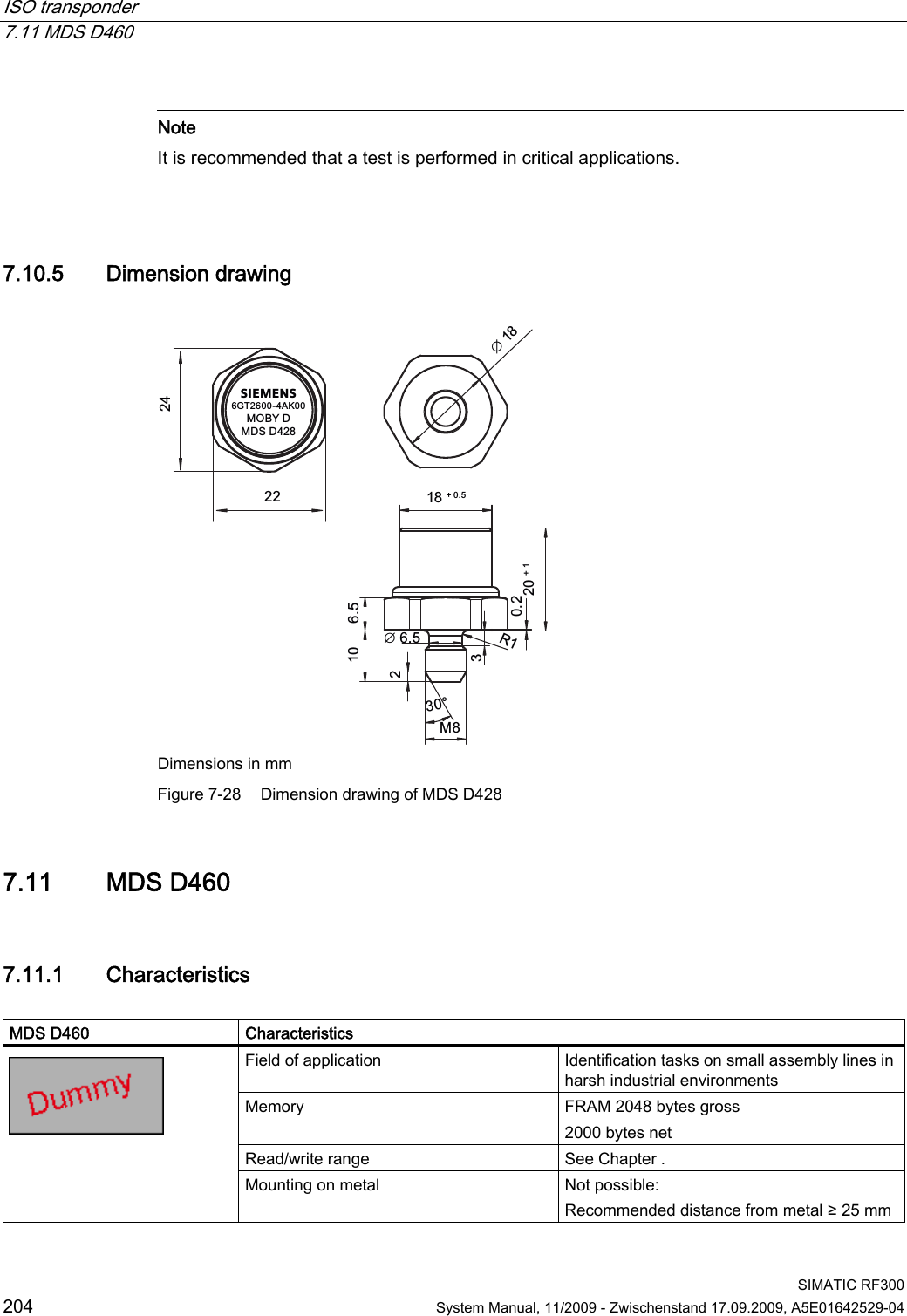
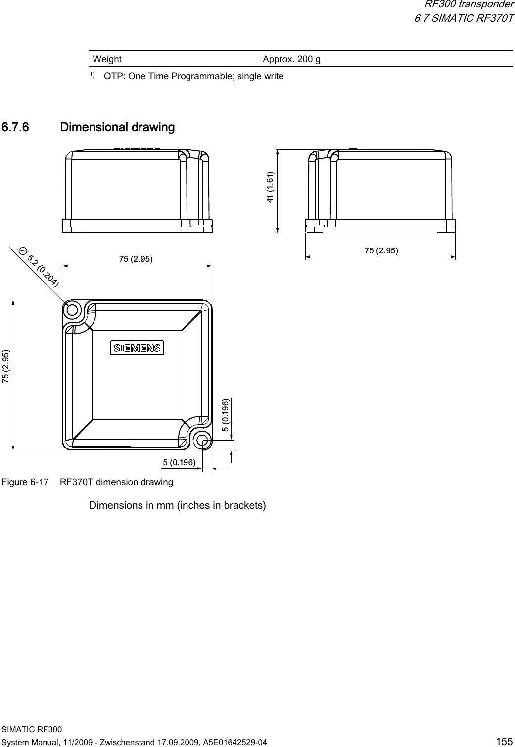
![RF300 transponder 6.7 SIMATIC RF370T SIMATIC RF300 154 System Manual, 11/2009 - Zwischenstand 17.09.2009, A5E01642529-04 6.7.4 Mounting instructions It is essential that you observe the instructions in the Section Installation guidelines (Page 62). Properties Description Type of installation Screw fixing (two M5 screws) Tightening torque < 1.2 Nm (at room temperature) 6.7.5 Technical data for RF370T with 32 KB FRAM Table 6- 11 Technical specifications for RF370T with 32 KB FRAM/64 KB FRAM Memory size 32 KB/64 KB Memory organization Blocks of 8 bits/byte-by-byte Serial number 4 bytes (fixed code) Application memory 32765 bytes r/w (32 KB) 65276 bytes r/w (64 KB) Memory configuration OTP 1) memory 20 bytes Storage technology FRAM / EEPROM MTBF (Mean Time Between Failures) in years 1200 Write cycles, at +40 °C Virtually unlimited (>1010) Read cycles Virtually unlimited (>1010) Read Approx. 0.13 ms/byte Data transmission time Write Approx. 0.13 ms/byte Data retention in years > 10 Read/write distance Dependent on the reader used [see Chapter Field data of RF300 transponders (Page 41)] Multitag capability max. 4 transponders Recommended spacing from metal can be directly mounted on metal Power supply Inductive, without battery Degree of protection to EN 60529 IPx9K Shock resistant to EN 60721-3-7 50 g Vibration resistant to EN 60721-3-7 20 g Torsion and bending load Not permissible continuously Enclosure dimensions 75 x 75 x 40 mm (L x W x H) Color Anthracite Material PA12 Fixing Two M5 screws Operation -25 °C to +85 °C Ambient temperature Transport and storage -40°C to +85°C](https://usermanual.wiki/Siemens/RF340R01.User-Manual-III/User-Guide-1196869-Page-5.png)
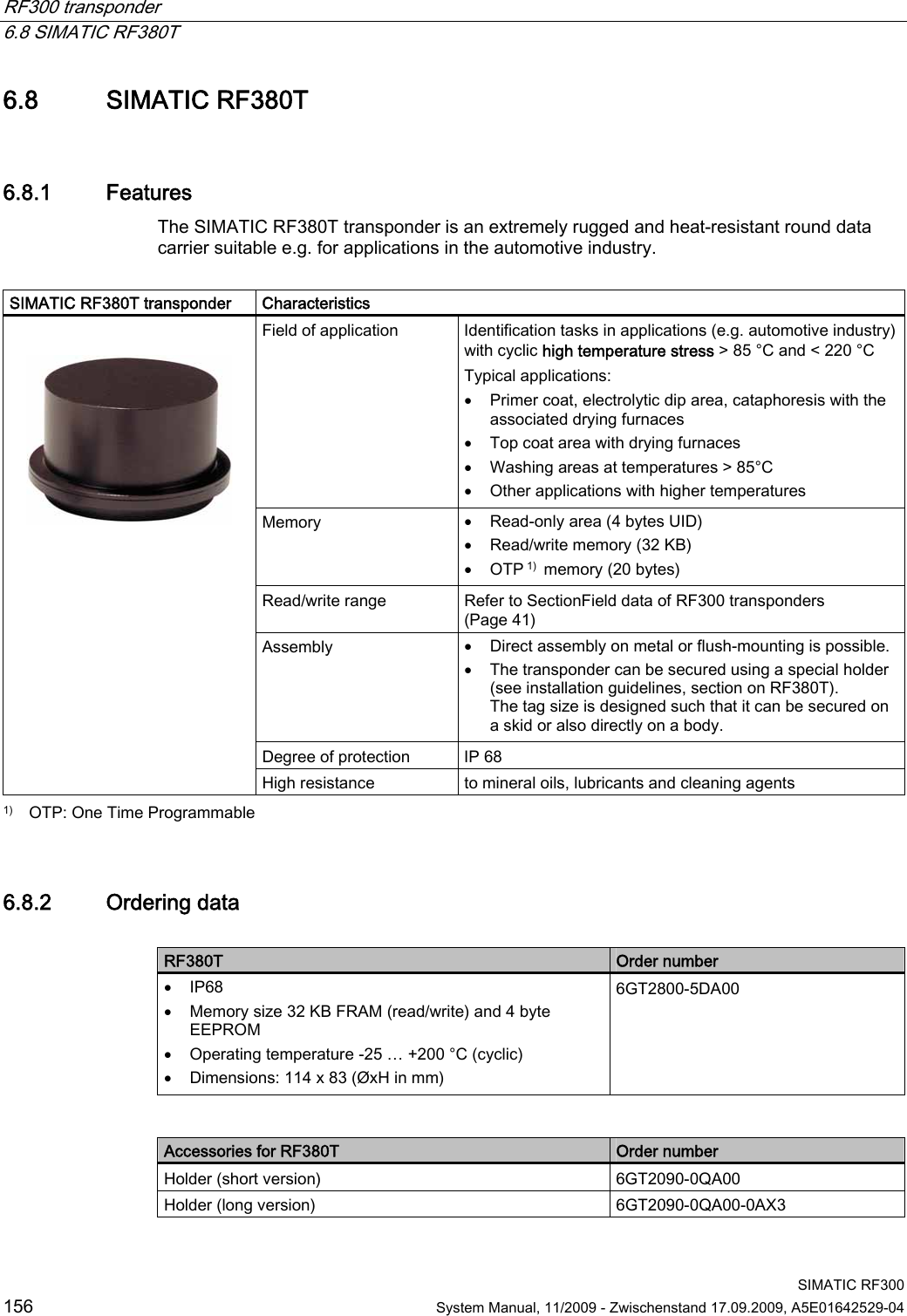
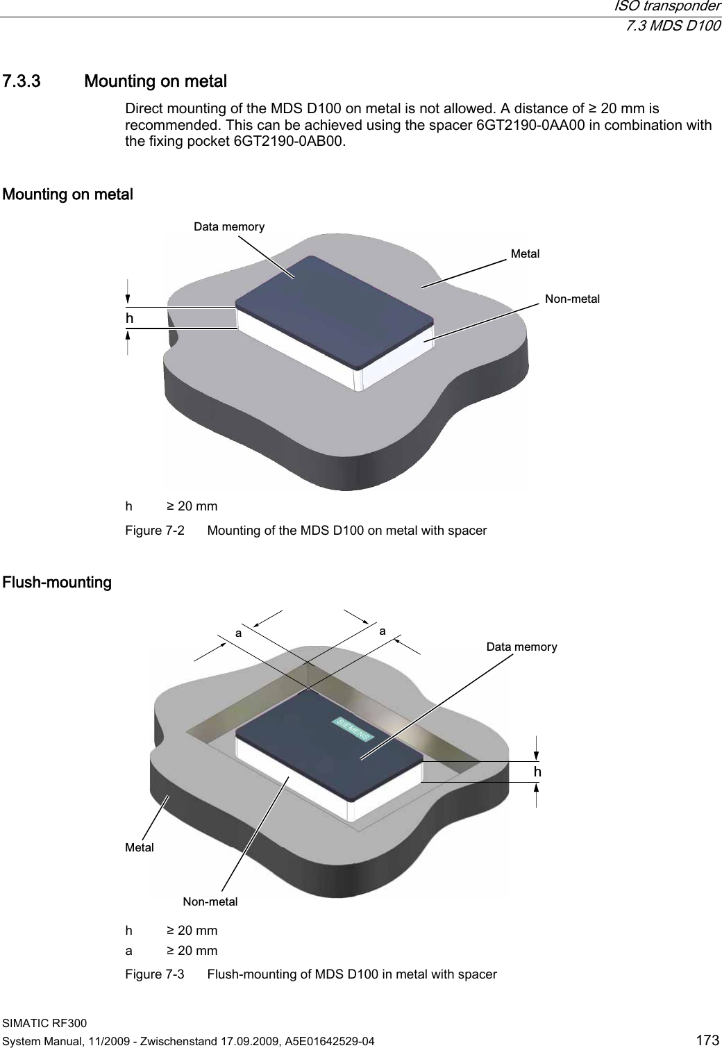
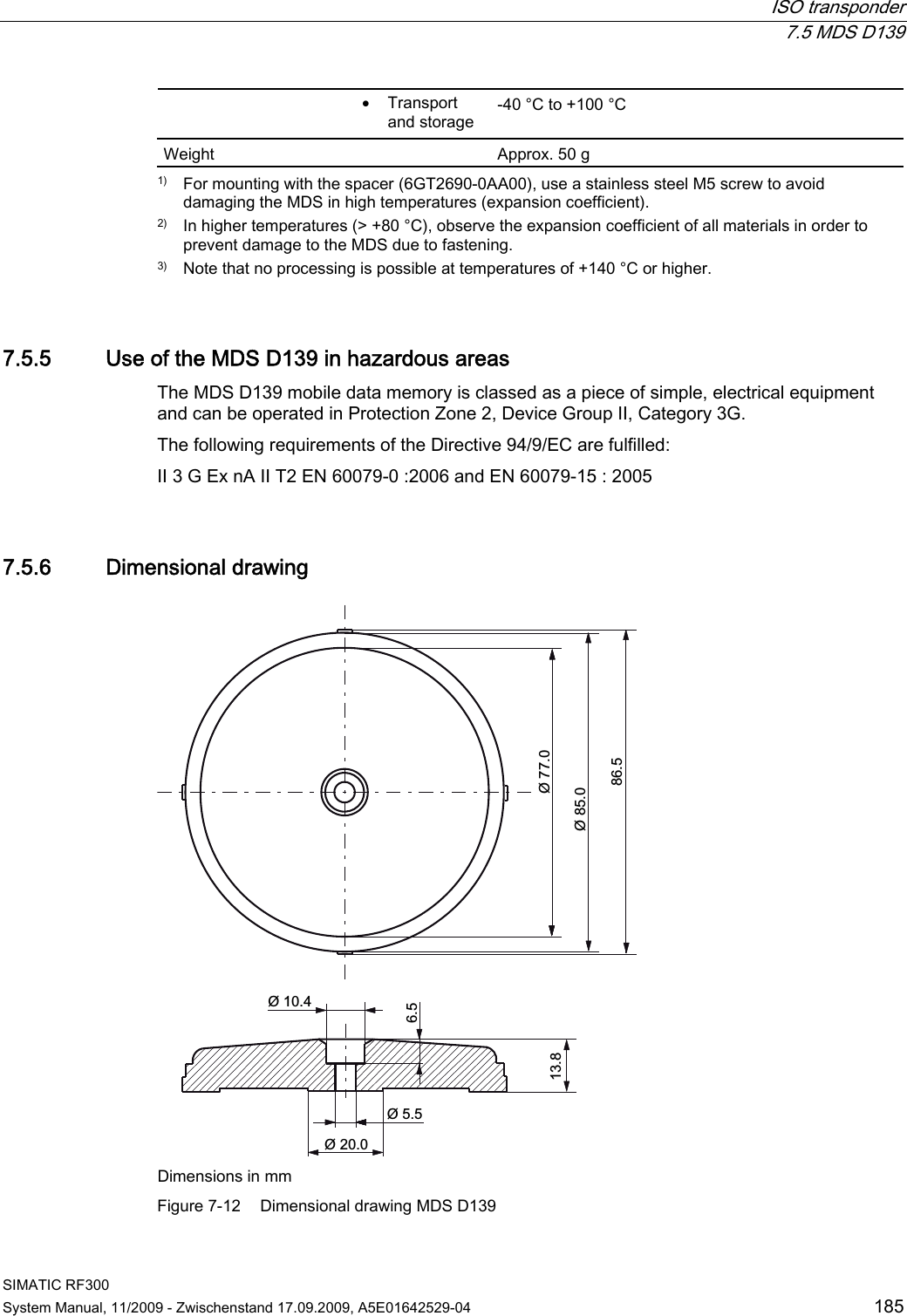
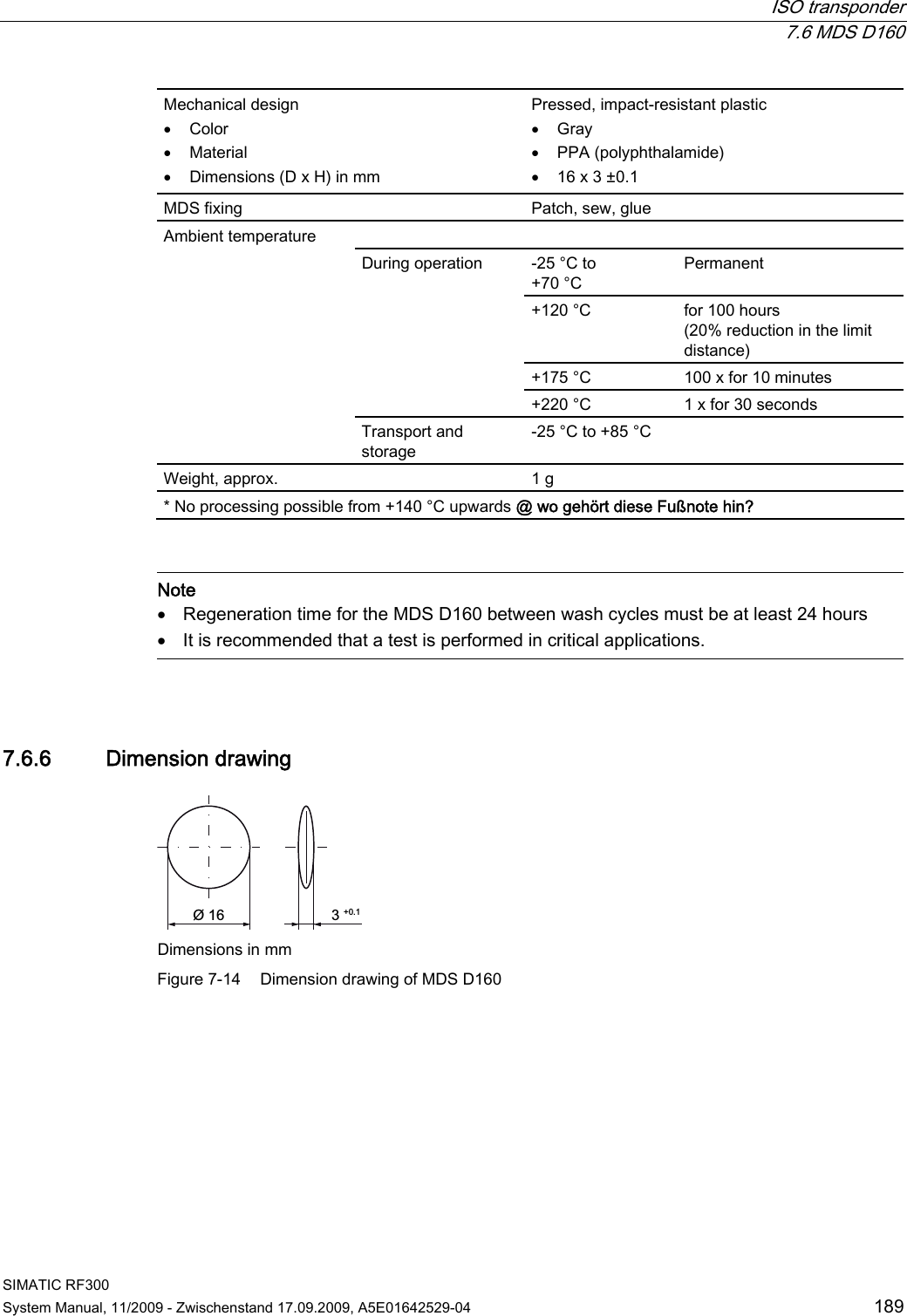
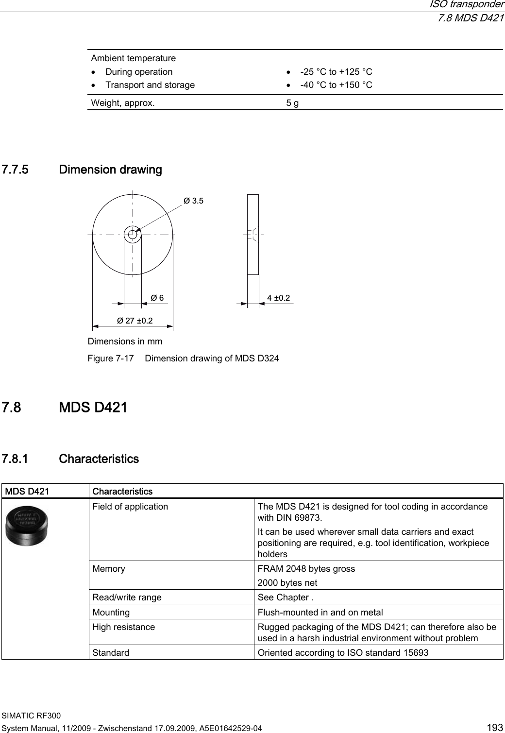
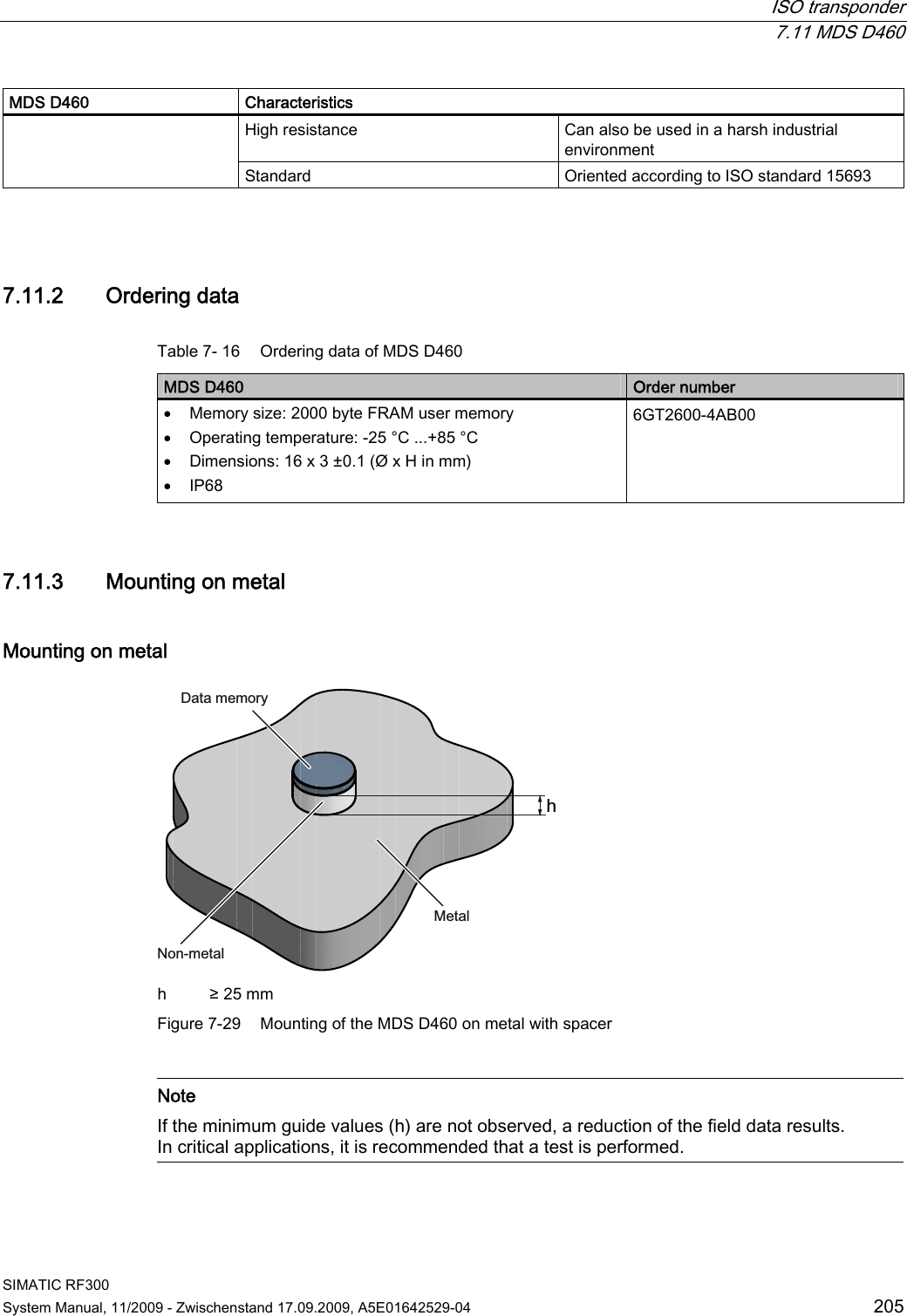
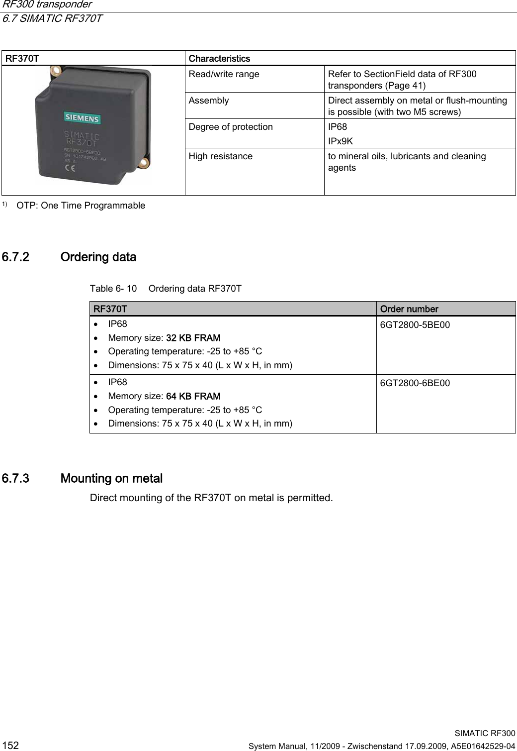
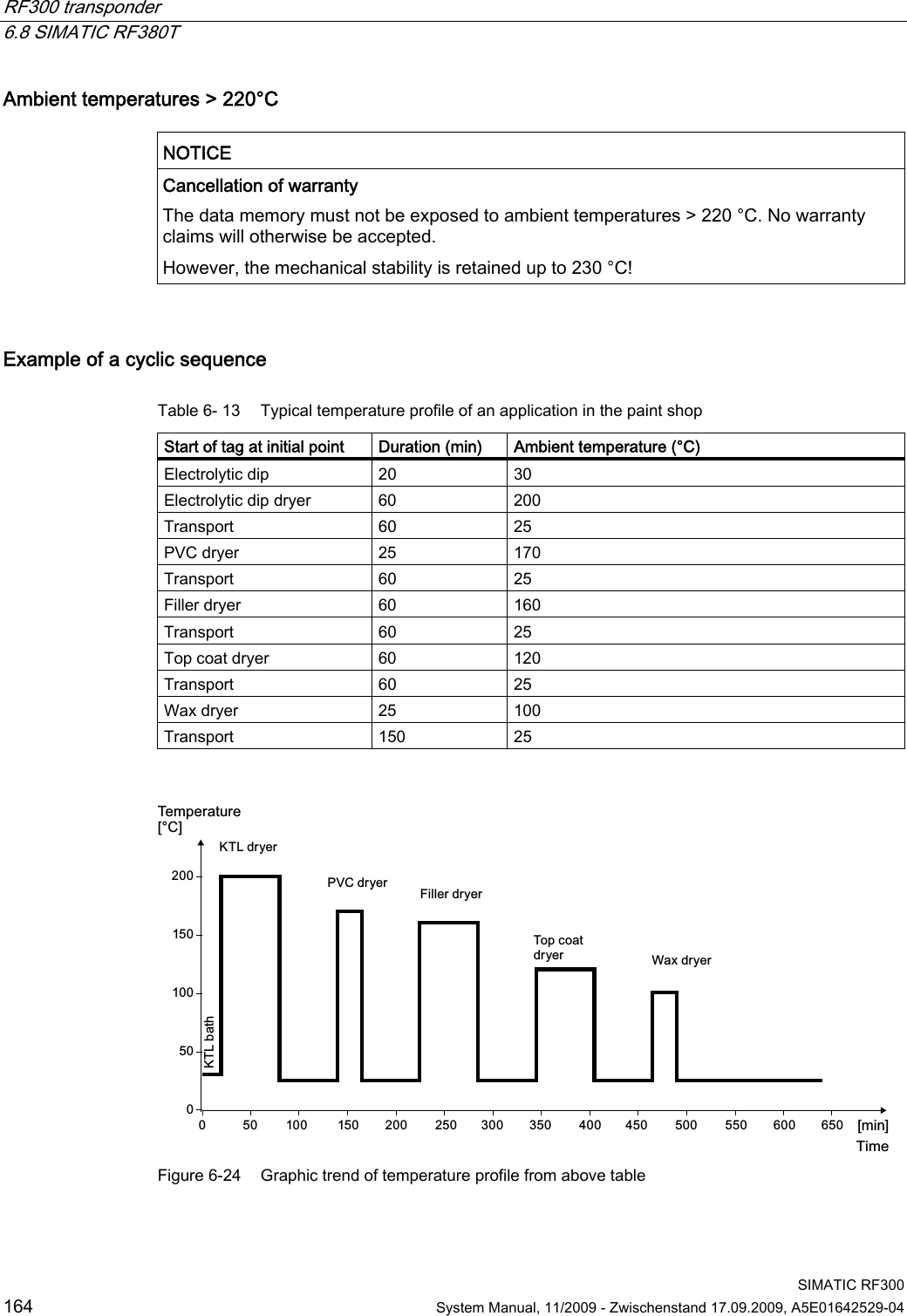
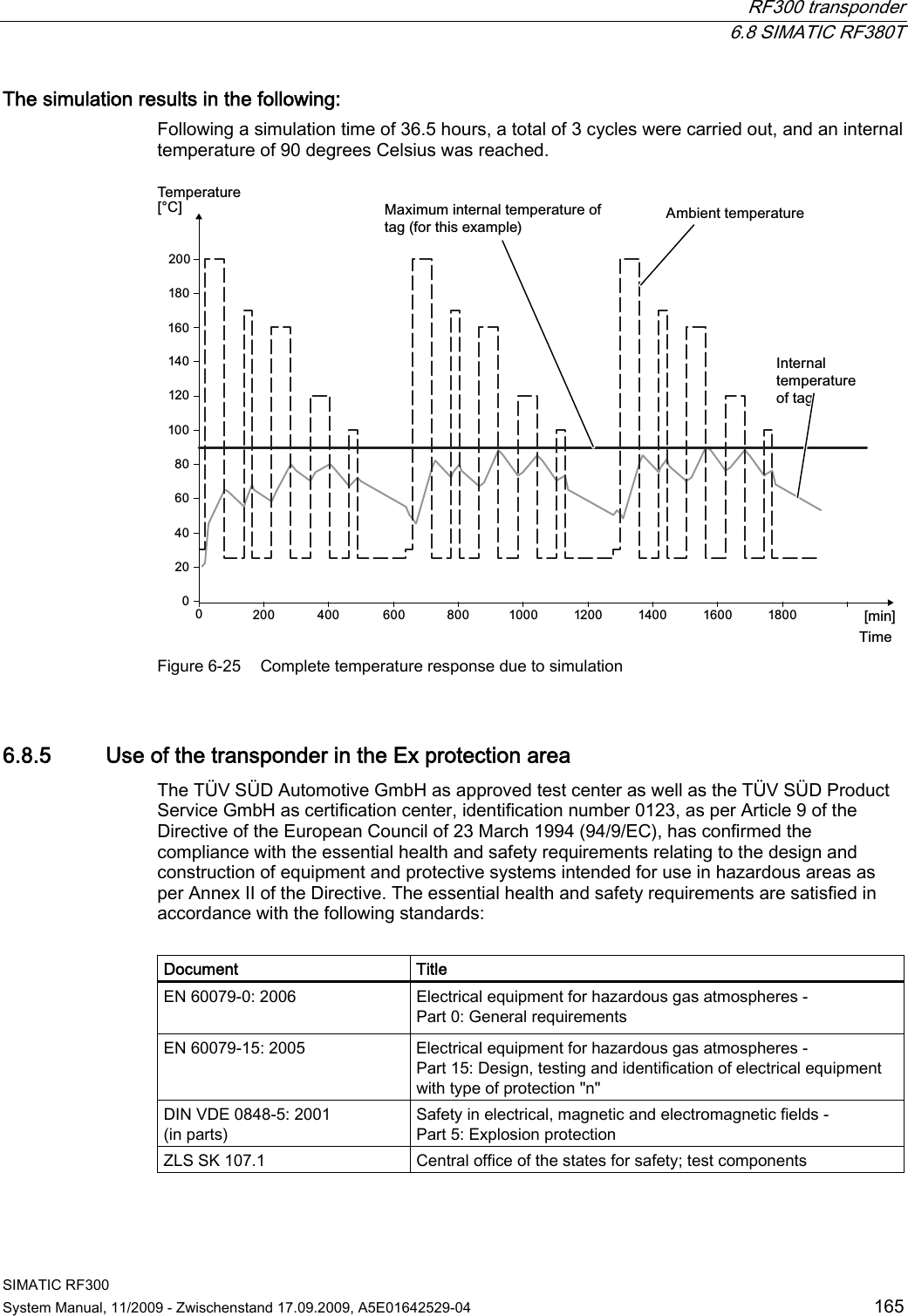
![RF300 transponder 6.8 SIMATIC RF380T SIMATIC RF300 System Manual, 11/2009 - Zwischenstand 17.09.2009, A5E01642529-04 163 6.8.4.2 Temperature response in cyclic operation At ambient temperatures (Tu) up to 110 °C, cyclic operation is not necessary, i.e. up to this temperature, the transponder can be in constant operation. Note Calculation of the temperature curves Calculation of the temperature curves or of a temperature profile can be carried out on request by Siemens AG. Exact knowledge of the internal temperature facilitates configuration for time-critical applications. You can also carry out the calculation with the aid of the "SIMATIC RF Temperature Calculator" on the "RFID Systems Software & Documentation" CD [see Accessories (Page 257)]. Ambient temperatures > 110 °C NOTICE Cancellation of warranty The internal temperature of the data memory must not exceed the critical threshold of 110 °C. Each heating phase must be followed by a cooling phase. No warranty claims will otherwise be accepted. Some limit cycles are listed in the table below: Table 6- 12 Limit cycles of data memory temperature Tu (heating up) Heating up Tu (cooling down) Cooling down 220 °C 0.5 h 25 °C > 2 h 200 °C 1 h 25 °C > 2 h 190 °C 1 h 25 °C > 1 h 45 min 180 °C 2 h 25 °C > 5 h 170 °C 2 h 25 °C > 4 h The internal temperature of the tag follows an exponential function with which the internal temperature and the operability of the tag can be calculated in advance. This is particularly relevant to temperature-critical applications or those with a complex temperature profile.](https://usermanual.wiki/Siemens/RF340R01.User-Manual-III/User-Guide-1196869-Page-14.png)
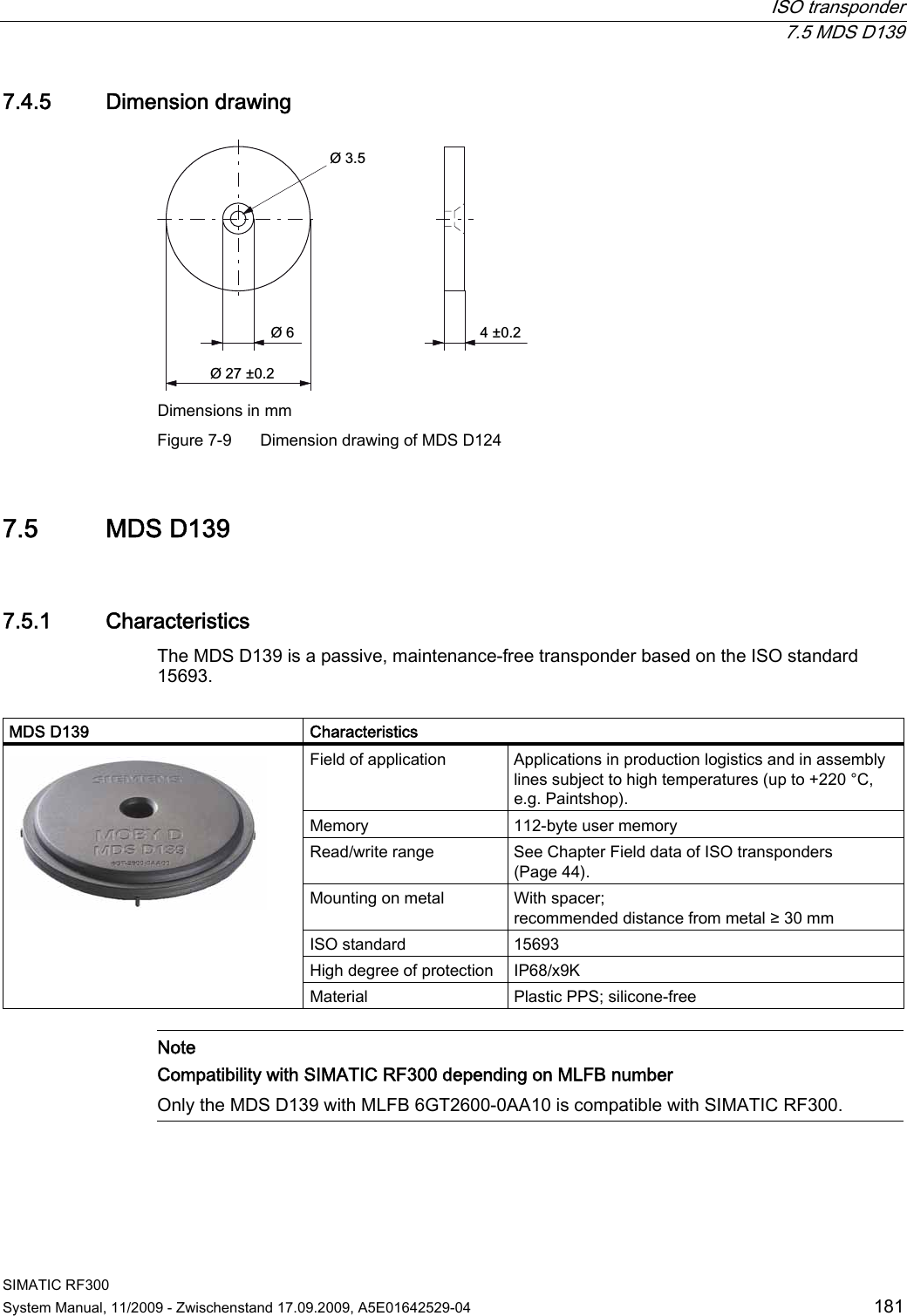
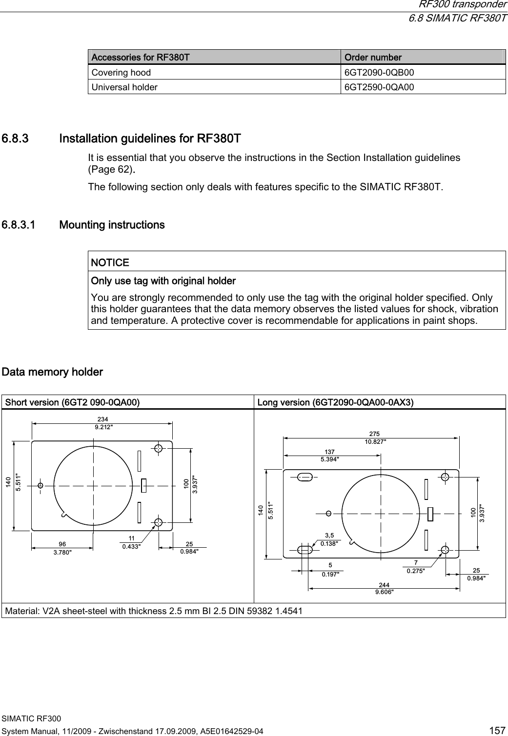
![RF300 transponder 6.8 SIMATIC RF380T SIMATIC RF300 166 System Manual, 11/2009 - Zwischenstand 17.09.2009, A5E01642529-04 Identification The identification of the electrical equipment as an enclosed unit is: II 3G Ex nC IIB T5 -25°C to +70°C Um = 30 V DC The equipment is assigned the following references: XXXYYYZZZ [= serial number, is assigned during production] TPS 09 ATEX 1 459 X [= certificate number] "No use of the equipment in the vicinity of processes generating high charges" 6.8.6 Use of the transponder in hazardous areas for gases Temperature class delineation for gases The temperature class of the transponder for hazardous areas depends on the ambient temperature range: Ambient temperature range Temperature class -25 °C to +70 °C T5 WARNING Ignitions of gas-air mixtures When using the RF380T transponder, check to ensure that the temperature class is observed in respect of the requirements of the area of application Non-compliance with the permitted temperature ranges while using the transponder can lead to ignitions of gas-air mixtures. WARNING Ignitions of gas-air mixtures The maximum transmitting power of the transmitter used to operate the transponder must not exceed 2 W. Non-compliance with the permissible transmitting power can lead to ignitions of gas-air mixtures.](https://usermanual.wiki/Siemens/RF340R01.User-Manual-III/User-Guide-1196869-Page-17.png)
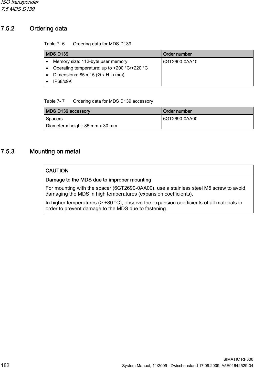
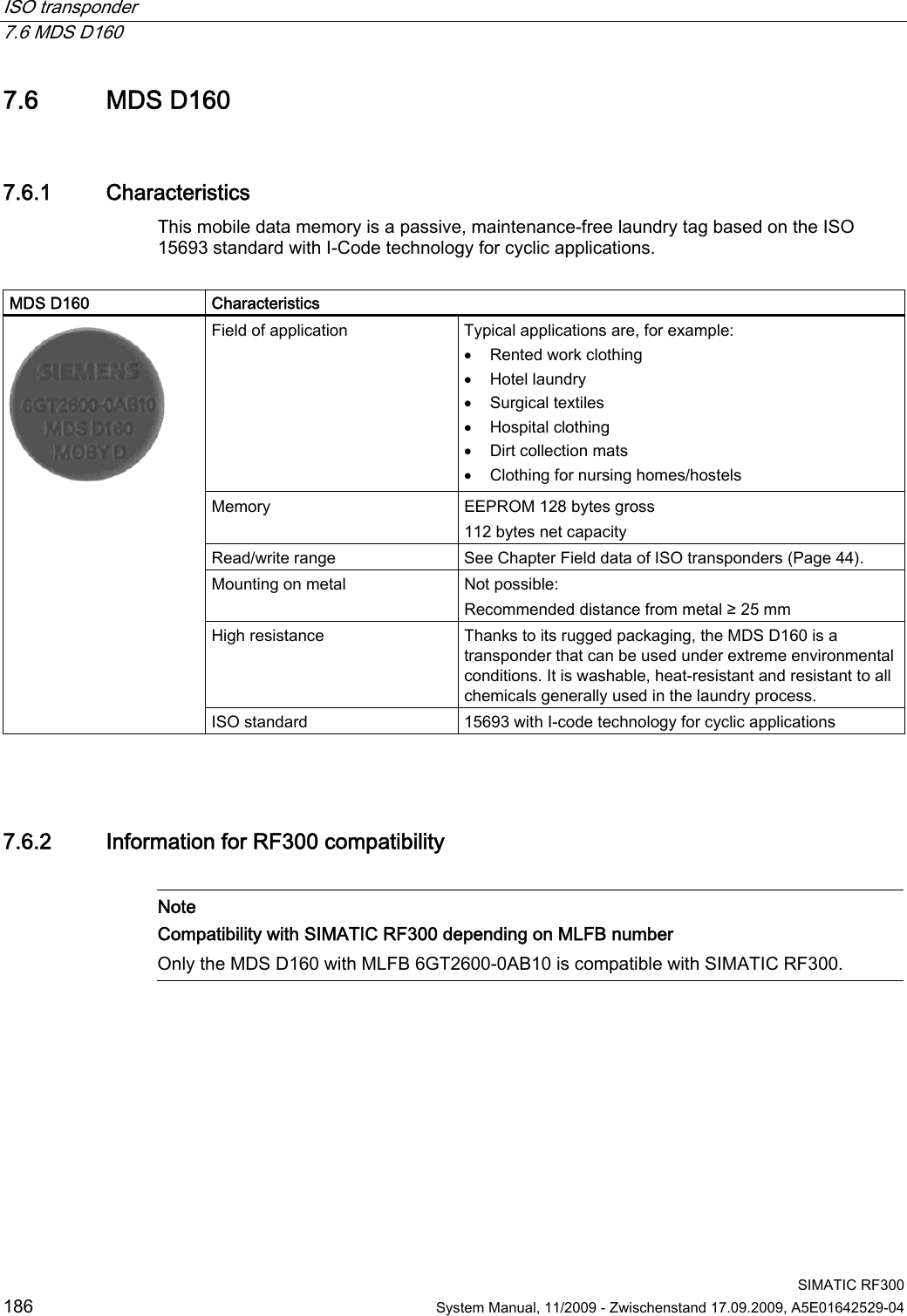
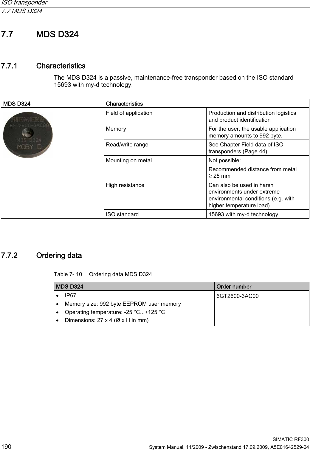
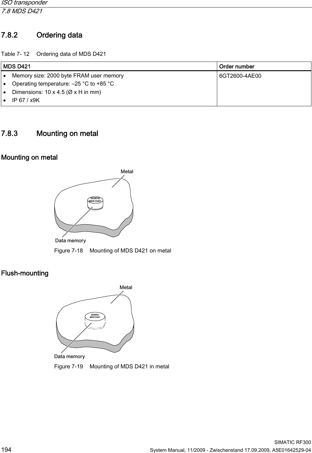
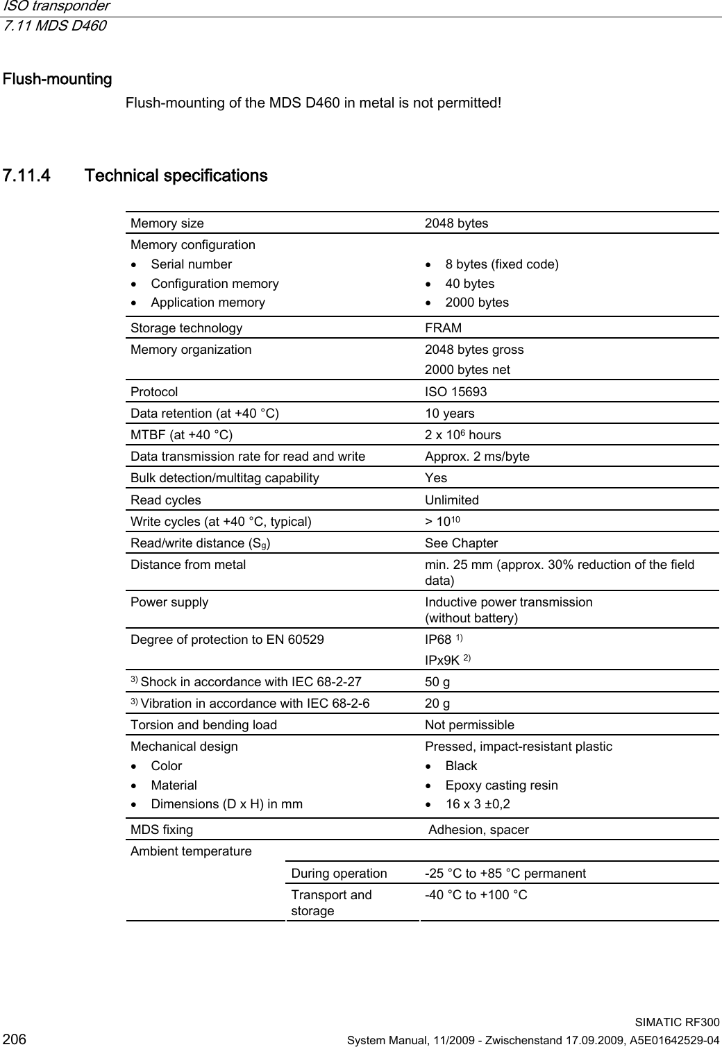
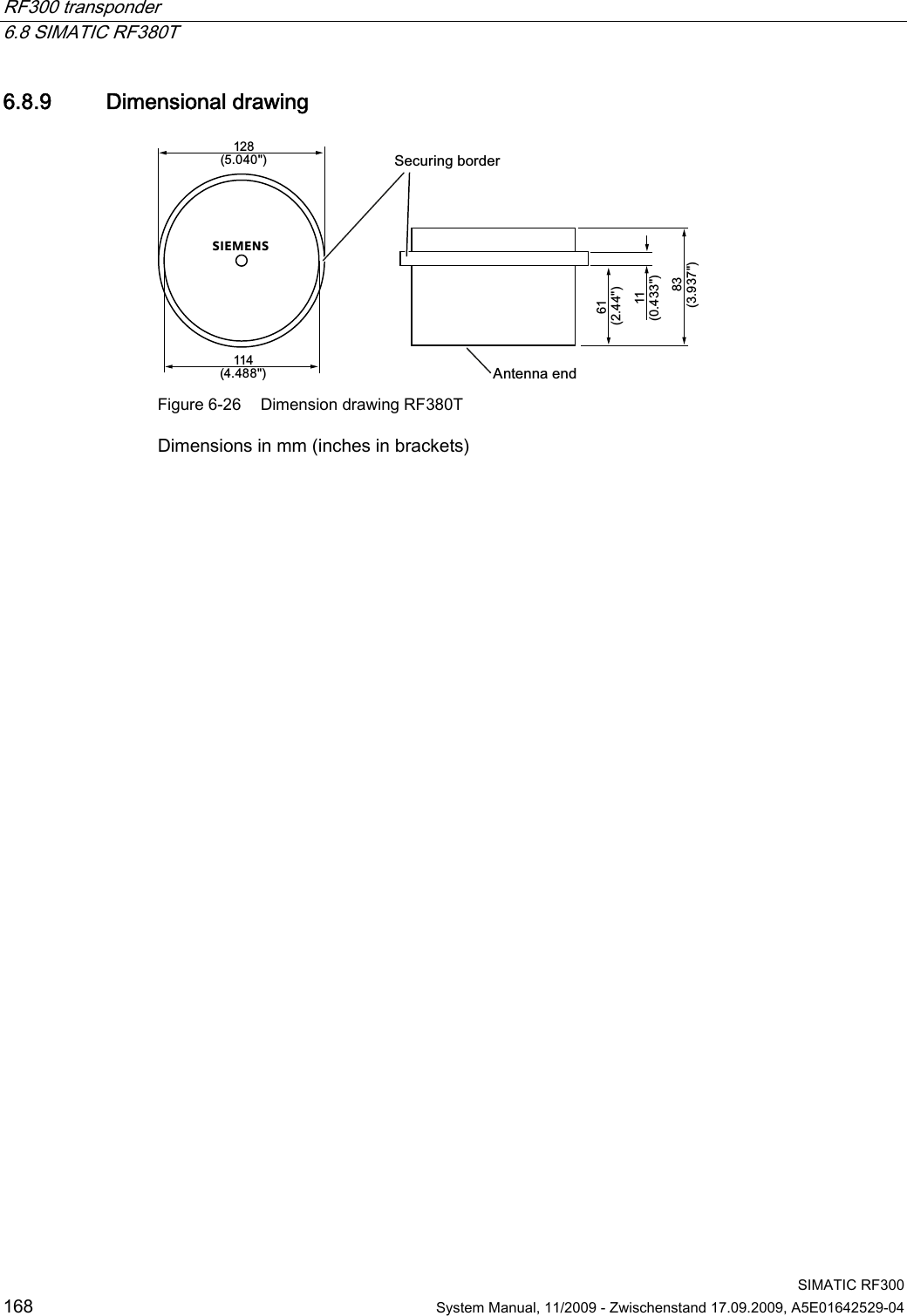
![RF300 transponder 6.8 SIMATIC RF380T SIMATIC RF300 System Manual, 11/2009 - Zwischenstand 17.09.2009, A5E01642529-04 167 6.8.7 Installation and operating conditions for the hazardous area a) Use of the equipment in the vicinity of processes generating high charges is not allowed. b) The equipment must be mechanically protected when installed. 6.8.8 Technical specifications Table 6- 14 RF380T with 32 KB FRAM Memory size 32KB Memory organization Blocks of 8 bits/byte-by-byte Serial number 4 bytes (fixed code) Application memory 32765 bytes r/w Memory configuration OTP 1) memory 20 bytes Storage technology FRAM / EEPROM MTBF (Mean Time Between Failures) in years 1177 Write cycles, at +40 °C Virtually unlimited (>1010) Read cycles Virtually unlimited (>1010) Read Approx. 0.13 ms/byte Data transmission time Write Approx. 0.13 ms/byte Data retention > 10 years Read/write distance Dependent on the reader used [see Chapter Field data of RF300 transponders (Page 41)] Multitag capability max. 4 transponders Recommended spacing from metal can be directly mounted on metal Power supply Inductive, without battery Degree of protection to EN 60529 IP68 Shock resistant2) to EN 60721-3-7 50 g Vibration2) to EN 60721-3-7 5 g Direction-dependent No Torsion and bending load Not permissible continuously Enclosure dimensions (diam. x H in mm) 114 x 83 Color Brown Material PPS Fixing Holder to be ordered separately During operation, continuously -25 °C to +110°C During cyclic operation -25 °C to +220°C Ambient temperature Transport and storage -40°C to +110°C Weight Approx. 900 g 1) OTP: One Time Programmable 2) Applies only in connection with original bracket](https://usermanual.wiki/Siemens/RF340R01.User-Manual-III/User-Guide-1196869-Page-18.png)
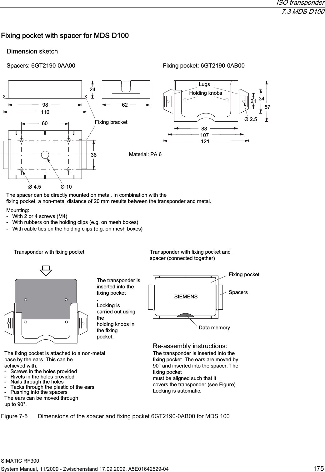
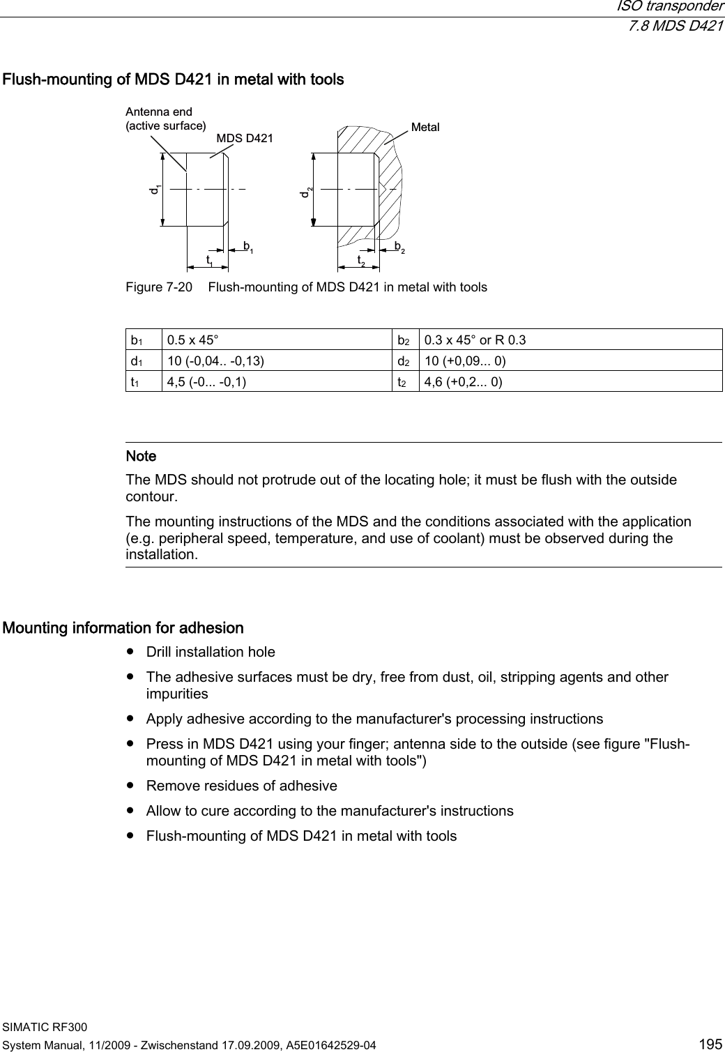
![SIMATIC RF300 System Manual, 11/2009 - Zwischenstand 17.09.2009, A5E01642529-04 169 ISO transponder 7 ISO 15693-compatible transponders, such as the MDS Dxxx from the MOBY D range of products, represent a cost-effective alternative to RF300 tags. The performance that can be achieved with this (data rate, memory size), however, is considerably less than with RF300 tags (see Chapter Communication between communication module, reader and transponder (Page 37)). Operating with the following ISO tags from MOBY D is described in this manual: ● MDS D100 ● MDS D124 ● MDS D139 ● MDS D160 ● MDS D324 ● MDS D421 ● MDS D424 ● MDS D428 ● MDS D460 Compatible RF300 readers ISO tags can currently only be processed using the following readers: ● SIMATIC RF310R (RS422) [6GT2801-1AB10] ● SIMATIC RF340R [6GT2801-2AB10] ● SIMATIC RF350R [6GT2801-4AB10] ● SIMATIC RF380R [6GT2801-3AB10]](https://usermanual.wiki/Siemens/RF340R01.User-Manual-III/User-Guide-1196869-Page-20.png)
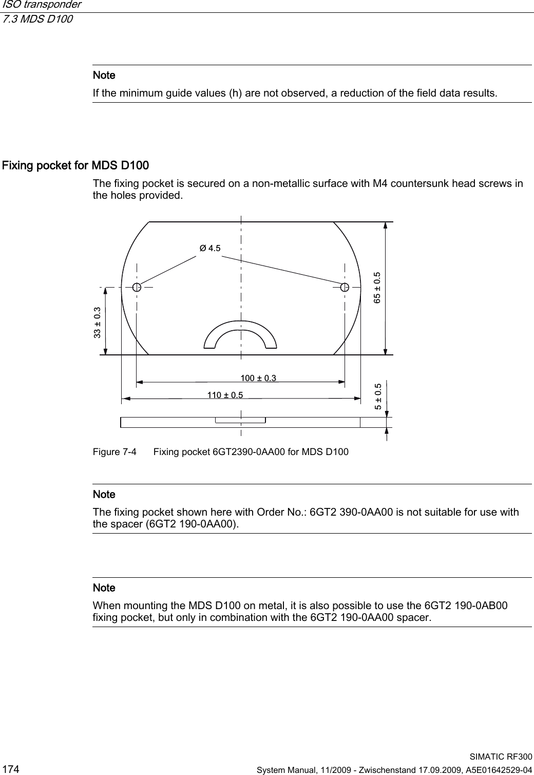
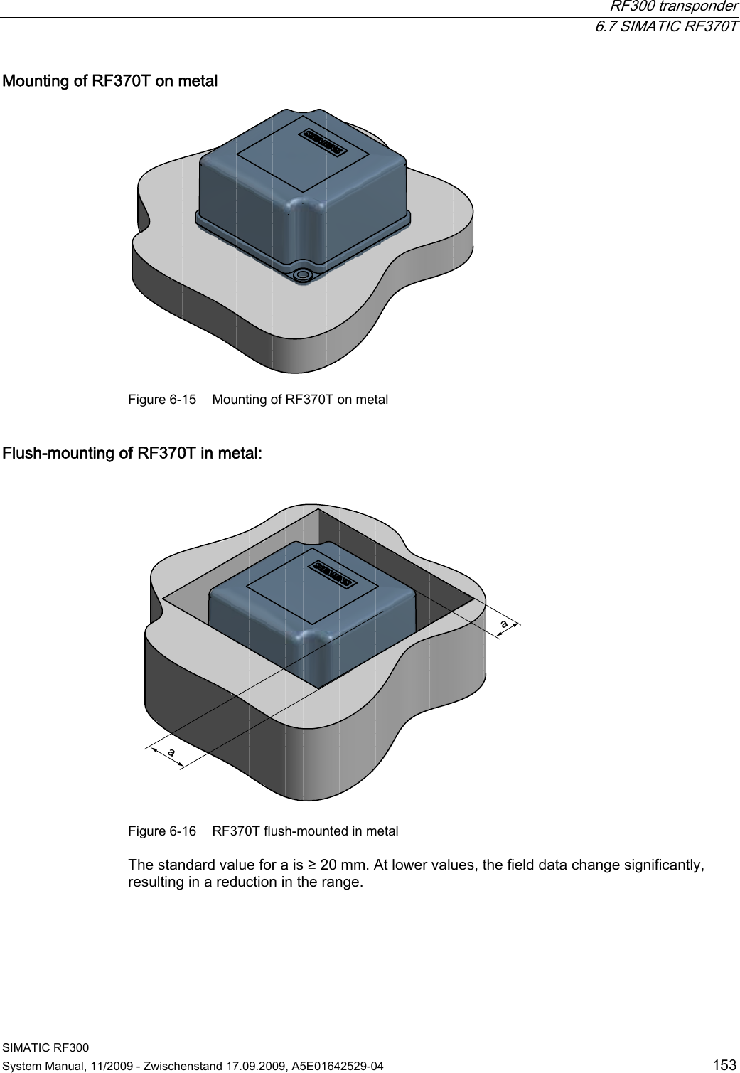
![ISO transponder 7.2 Memory configuration of the ISO tags SIMATIC RF300 170 System Manual, 11/2009 - Zwischenstand 17.09.2009, A5E01642529-04 7.2 Memory configuration of the ISO tags E\WHV8,'UHDGRQO\8VHUDUHDUHDGZULWH((3520273PD[EORFNVRIE\WHVHDFK0'6'7DJLW+),67/5,.E\WH((3520E\WHEORFNVL]HE\WH)5$0E\WHEORFNVL]H,&2'(6/,E\WH((3520E\WHEORFNVL]H,QILQHRQP\GE\WH((3520E\WHEORFNVL]H0'6'0'6'0'6'0'6'))))))))'))))&))))&))XMLWVX0%5))))0'6'1'6'0'6'0'6' 1) If the OTP area is used, there will be a correspondingly lower amount of user memory available, because the OTP area always occupies the uppermost 16 bytes of the user memory.Figure 7-1 Memory configuration of ISO tags](https://usermanual.wiki/Siemens/RF340R01.User-Manual-III/User-Guide-1196869-Page-21.png)