Siemens RF340R01 Inductive Tag Reader User Manual SIMATIC RF300
Siemens AG Inductive Tag Reader SIMATIC RF300
UserManual.wiki
>
Siemens
>
RF340R01 User Manual
>
User Manual II
Contents
1.
User Manual I
2.
User Manual II
3.
User Manual III
4.
User Manual IV
User Manual II
Navigation menu
Upload a User Manual
Namespaces
Wiki Guide
HTML
PDF
Info
Views
User Manual
Discussion / Help
Navigation
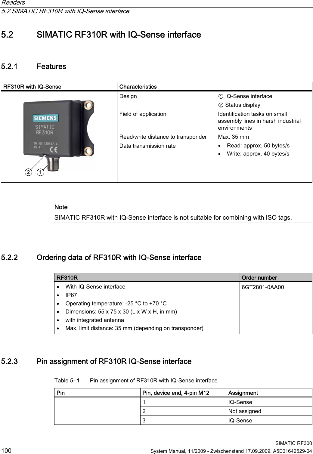
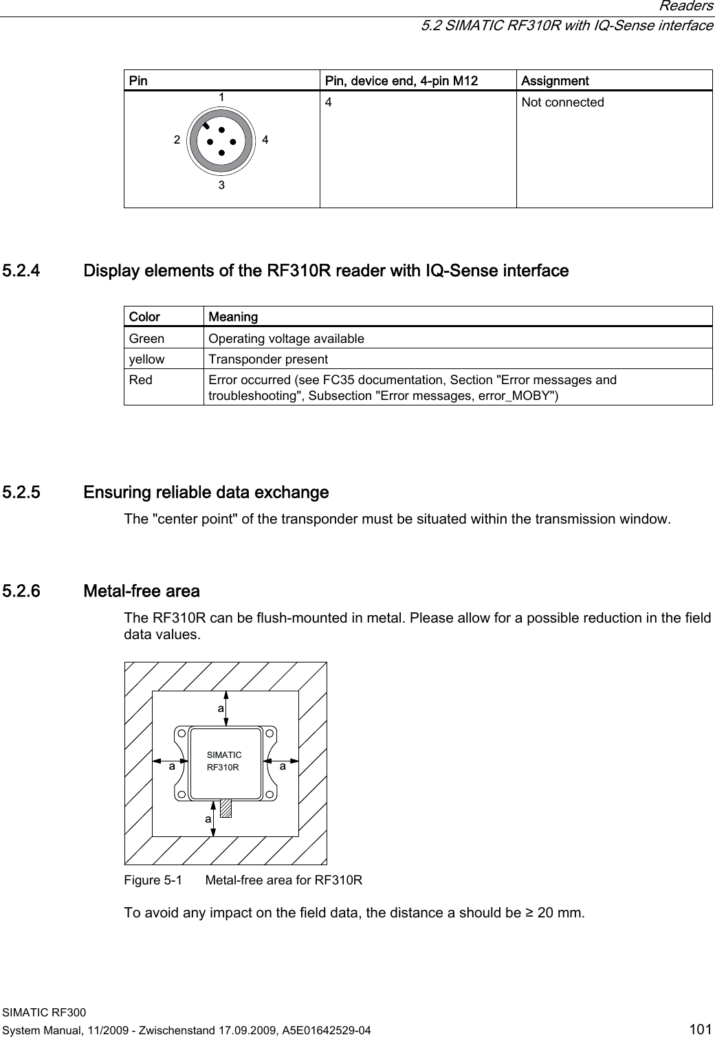
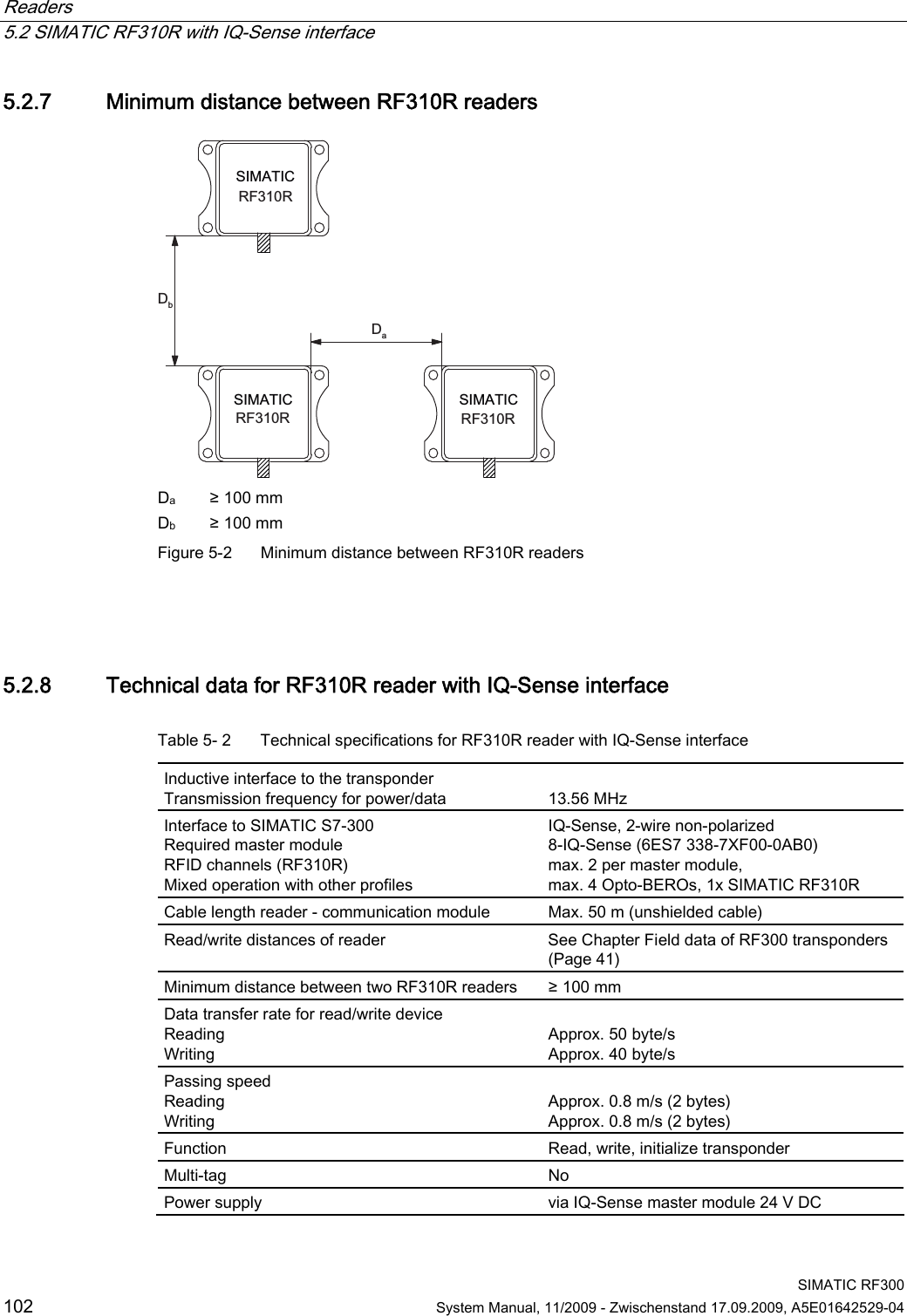
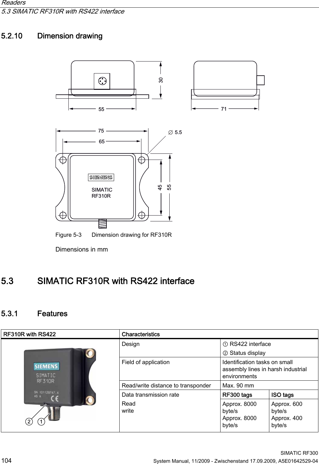
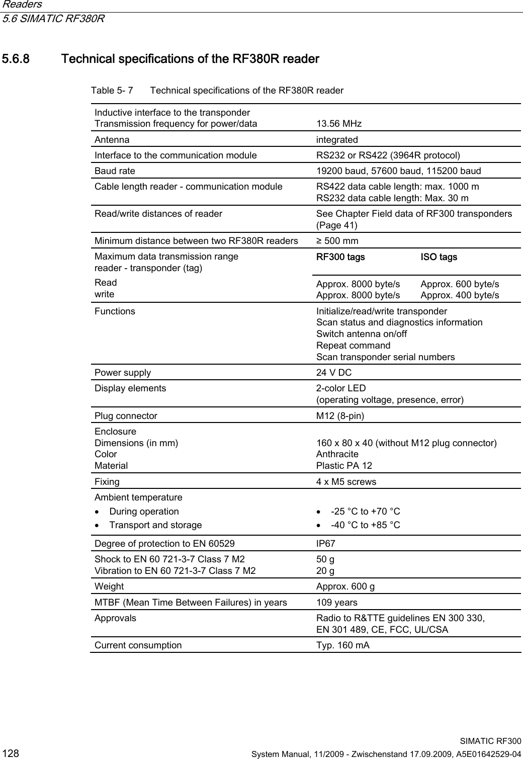
![Readers 5.6 SIMATIC RF380R SIMATIC RF300 System Manual, 11/2009 - Zwischenstand 17.09.2009, A5E01642529-04 129 5.6.9 FCC information Siemens SIMATIC RF380R (MLFB 6GT2801-3AA10) FCC ID: NXW-RF380R Siemens SIMATIC RF380R (MLFB 6GT2801-3AB10) FCC ID: NXW-RF380R01 This device complies with part 15 of the FCC rules. Operation is subject to the following two conditions: (1) This device may not cause harmful interference. (2) This device must accept any interference received, including interference that may cause undesired operation. Caution Any changes or modifications not expressly approved by the party responsible for compliance could void the user's authority to operate the equipment. 5.6.10 Use of the reader in hazardous areas The TÜV SÜD Automotive GmbH as approved test center as well as the TÜV SÜD Product Service GmbH as certification center, identification number 0123, as per Article 9 of the Directive of the European Council of 23 March 1994 (94/9/EC), has confirmed the compliance with the essential health and safety requirements relating to the design and construction of equipment and protective systems intended for use in hazardous areas as per Annex II of the Directive. The essential health and safety requirements are satisfied in accordance with the following standards: Document Title EN 60079-0: 2006 Electrical equipment for hazardous gas atmospheres - Part 0: General requirements EN 60079-15: 2005 Electrical equipment for hazardous gas atmospheres - Part 15: Design, testing and identification of electrical equipment with type of protection "n" DIN VDE 0848-5: 2001 (in parts) Safety in electrical, magnetic and electromagnetic fields - Part 5: Explosion protection ZLS SK 107.1 Central office of the states for safety; test components Identification The identification of the electrical equipment as an enclosed unit is: II 3G Ex nC IIB T5 -25 °C to +70 °C Um = 30 V DC The equipment is assigned the following references: XXXYYYZZZ [= serial number, is assigned during production] TPS 09 ATEX 1 459 X [= certificate number]](https://usermanual.wiki/Siemens/RF340R01.User-Manual-II/User-Guide-1196868-Page-30.png)
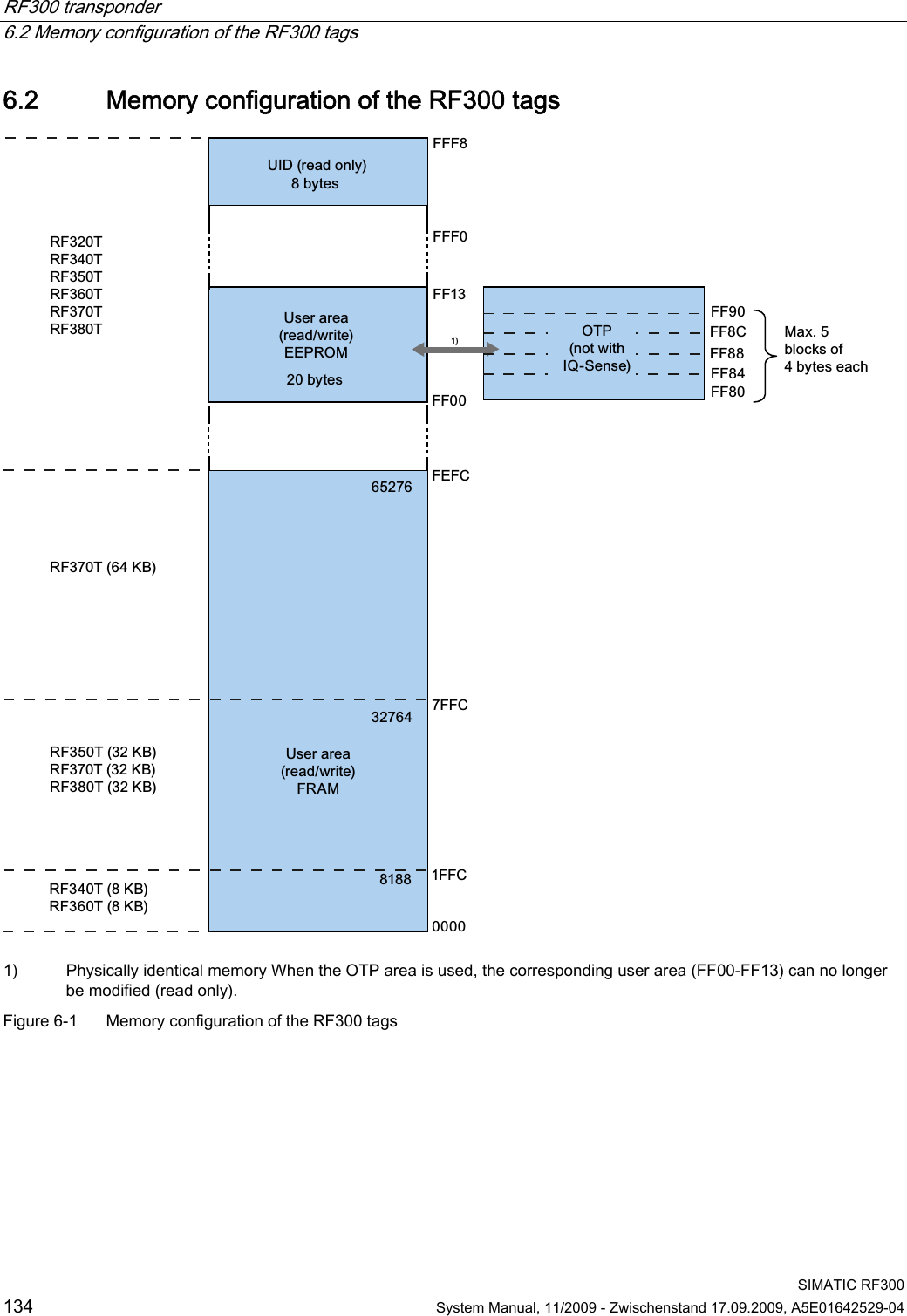
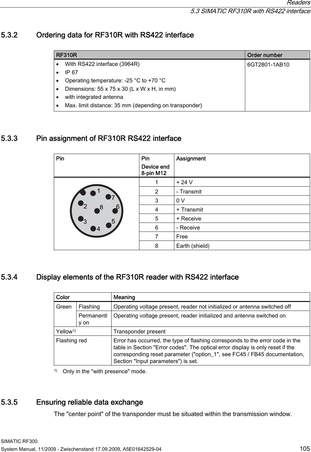
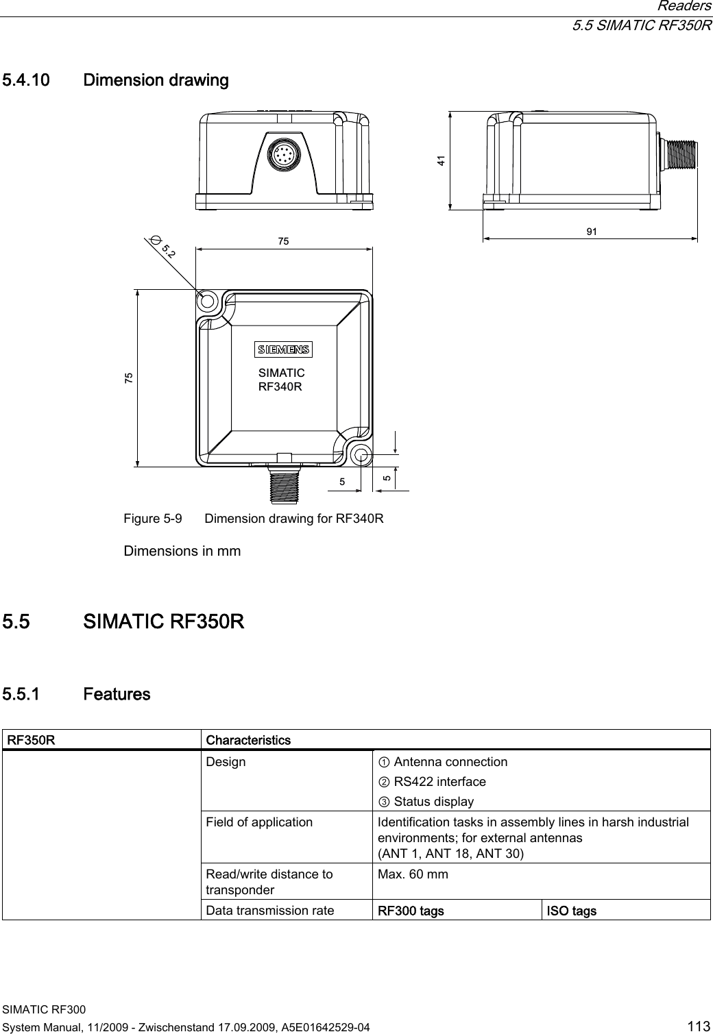
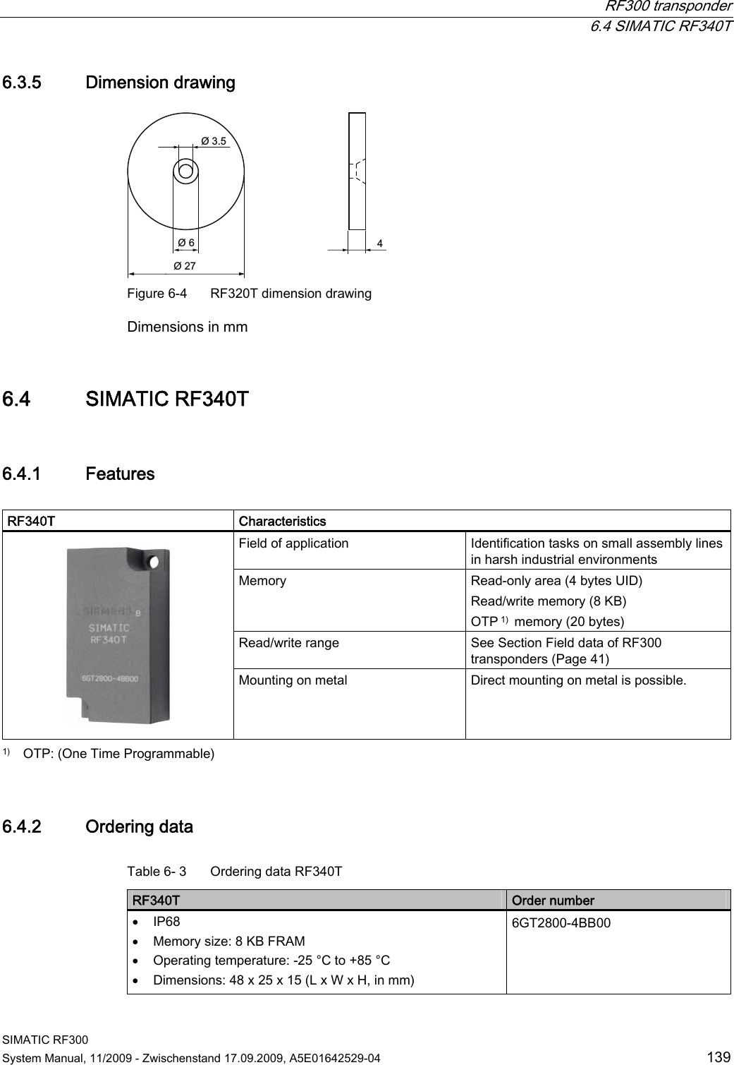
![RF300 transponder 6.3 SIMATIC RF320T SIMATIC RF300 138 System Manual, 11/2009 - Zwischenstand 17.09.2009, A5E01642529-04 6.3.4 Technical data Table 6- 2 Technical data for RF320T Memory size 20 bytes EEPROM (r/w), 4 bytes UID (ro) Memory organization Byte-oriented access, write protection possible in 4-byte blocks MTBF (Mean Time Between Failures) in years 1800 Read cycles Unlimited Write cycles, min. 50 000 at ≤ 40 °C, typical > 100 000 Data retention time > 10 years (at < +40 °C) Read/write distance Dependent on the reader used [see Chapter Field data of RF300 transponders (Page 41) ] Energy source Inductive power transmission Shock/vibration-resistant to EN 60721-3-7, Class 7 M3 100 g/20 g Torsion and bending load Not permissible Fixing Adhesive/M3 screws Recommended spacing from metal > 20 mm Degree of protection to EN 60529 IP67/IPX9K Housing Dimensions Color/material Button Ø 27 mm x 4 mm Black/epoxy resin Ambient temperature Operation Transport and storage -25 to +85 °C -40 to +125 °C Weight Approx. 5 g Note All the technical data listed are typical data and are applicable for an ambient temperature between 0 and +50 °C and a metal-free environment.](https://usermanual.wiki/Siemens/RF340R01.User-Manual-II/User-Guide-1196868-Page-39.png)
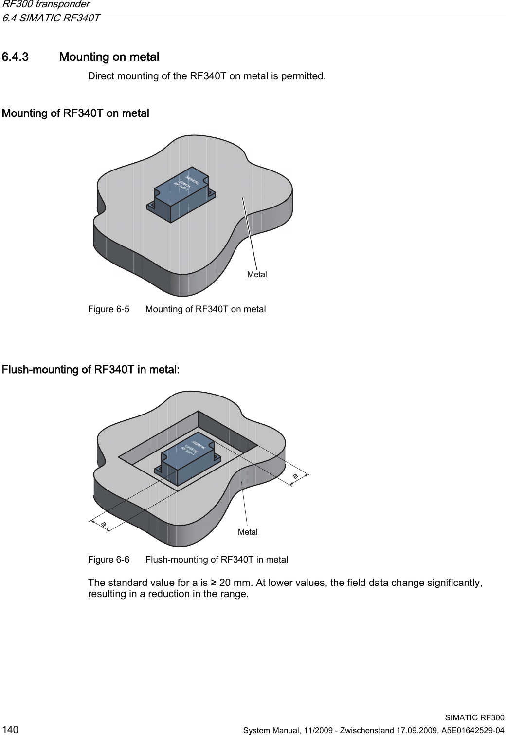
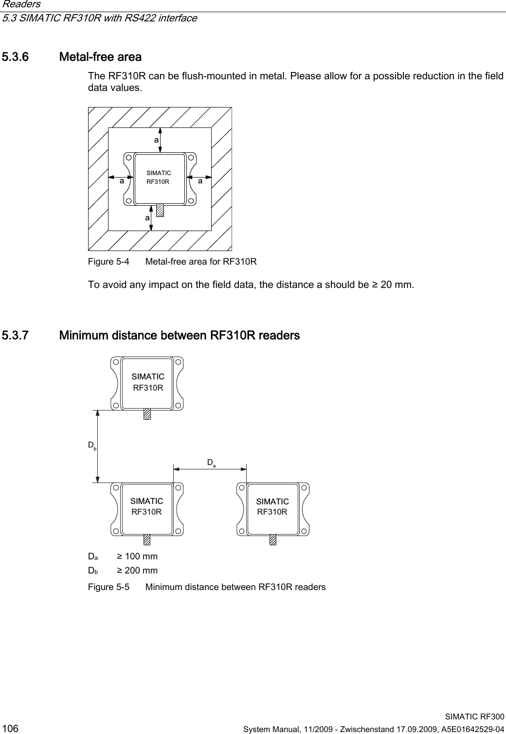
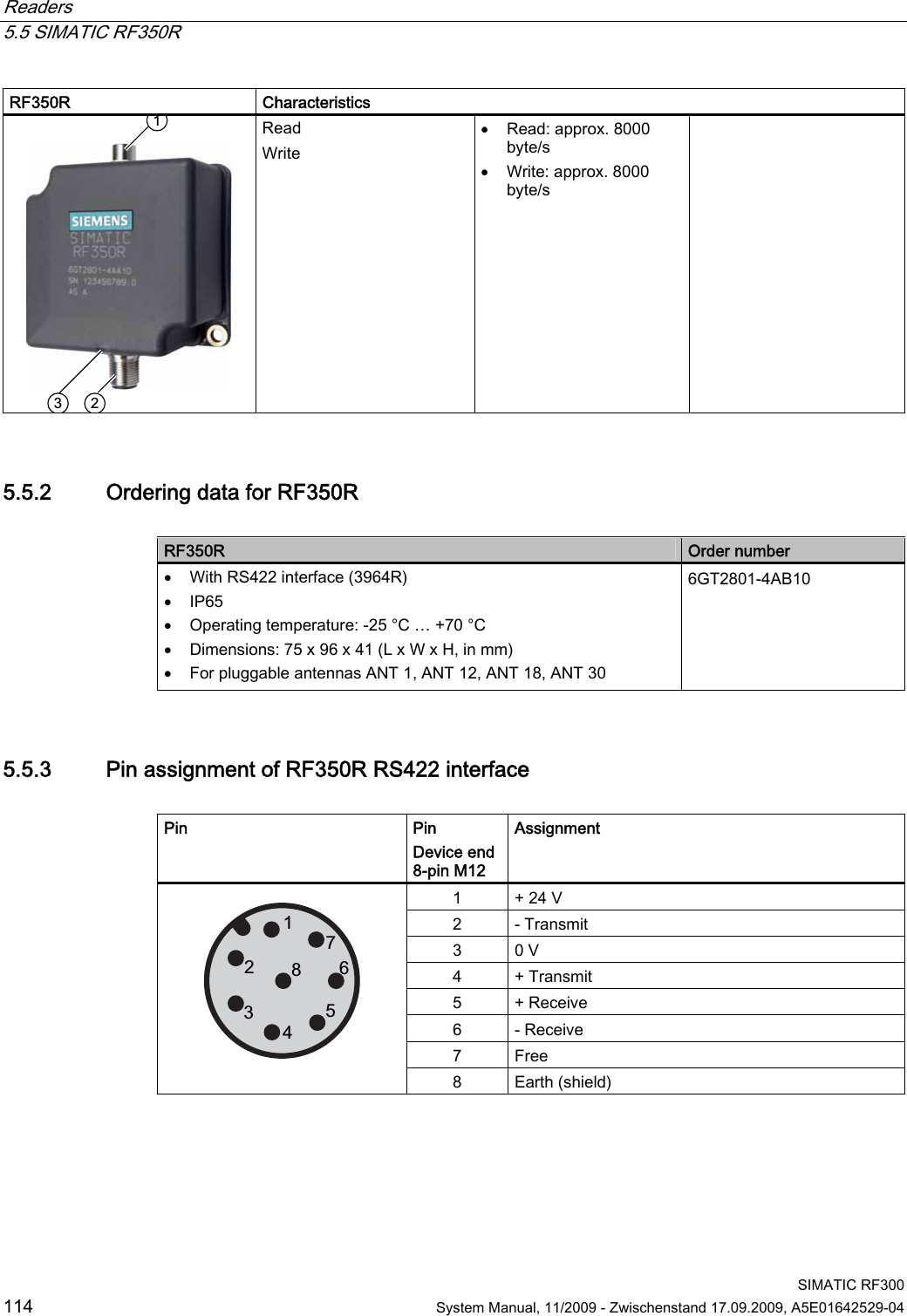
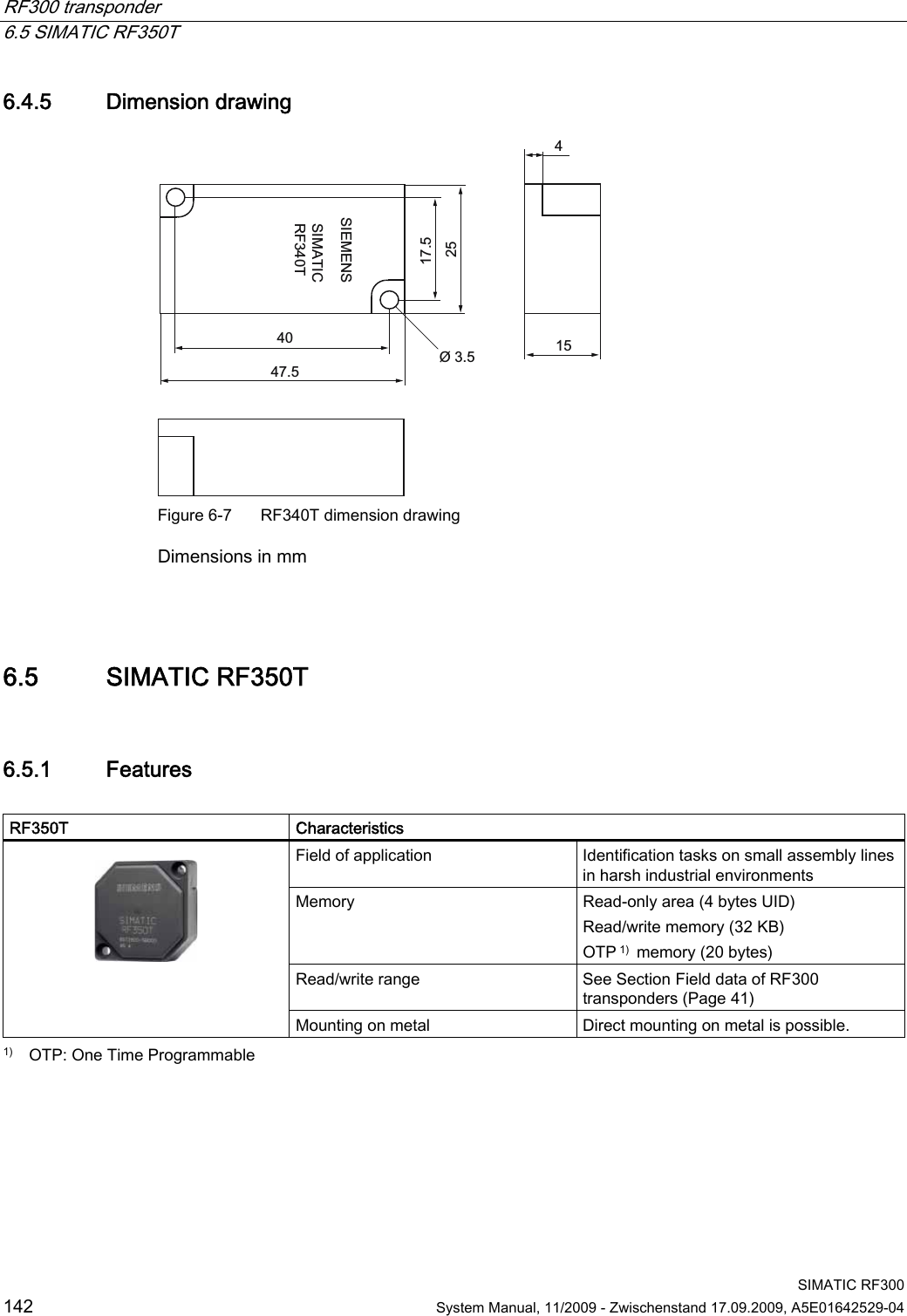
![RF300 transponder 6.4 SIMATIC RF340T SIMATIC RF300 System Manual, 11/2009 - Zwischenstand 17.09.2009, A5E01642529-04 141 6.4.4 Technical specifications Table 6- 4 Technical specifications for RF340T Memory size 8 KB Memory organization Blocks of 8 bits/byte-by-byte Memory configuration Serial number (UID) Application memory OPT memory 4 bytes (fixed code) 8189 bytes r/w 20-byte OTP 1) memory Storage technology FRAM / EEPROM MTBF (Mean Time Between Failures) in years 1200 Write cycles, at +40 °C Virtually unlimited (>1010) Read cycles Virtually unlimited (>1010) Data transmission time Read Write With RS422 reader: Approx. 0.13 ms/byte approx. 0.13 ms/byte With IQ-Sense reader: Approx. 20 ms/byte approx. 25 ms/byte Data retention > 10 years Read/write distance Dependent on the reader used [see Chapter Field data of RF300 transponders (Page 41)] Multitag capability max. 4 transponders Recommended spacing from metal can be directly mounted on metal Power supply Inductive, without battery Degree of protection to EN 60529 Shock to EN 60721-3-7 Vibration to EN 60721-3-7 Torsion and bending load IP68/IPX9K 50 g 20 g Not permitted permanently Enclosure dimensions Color Material Fixing 48 x 25 x 15 mm (L x W x H) Anthracite PA12 2 screws (M3) Ambient temperature Operation Storage and transport -25°C to +85°C -40°C to +85°C Weight Approx. 25 g 1) OTP: One Time Programmable](https://usermanual.wiki/Siemens/RF340R01.User-Manual-II/User-Guide-1196868-Page-42.png)
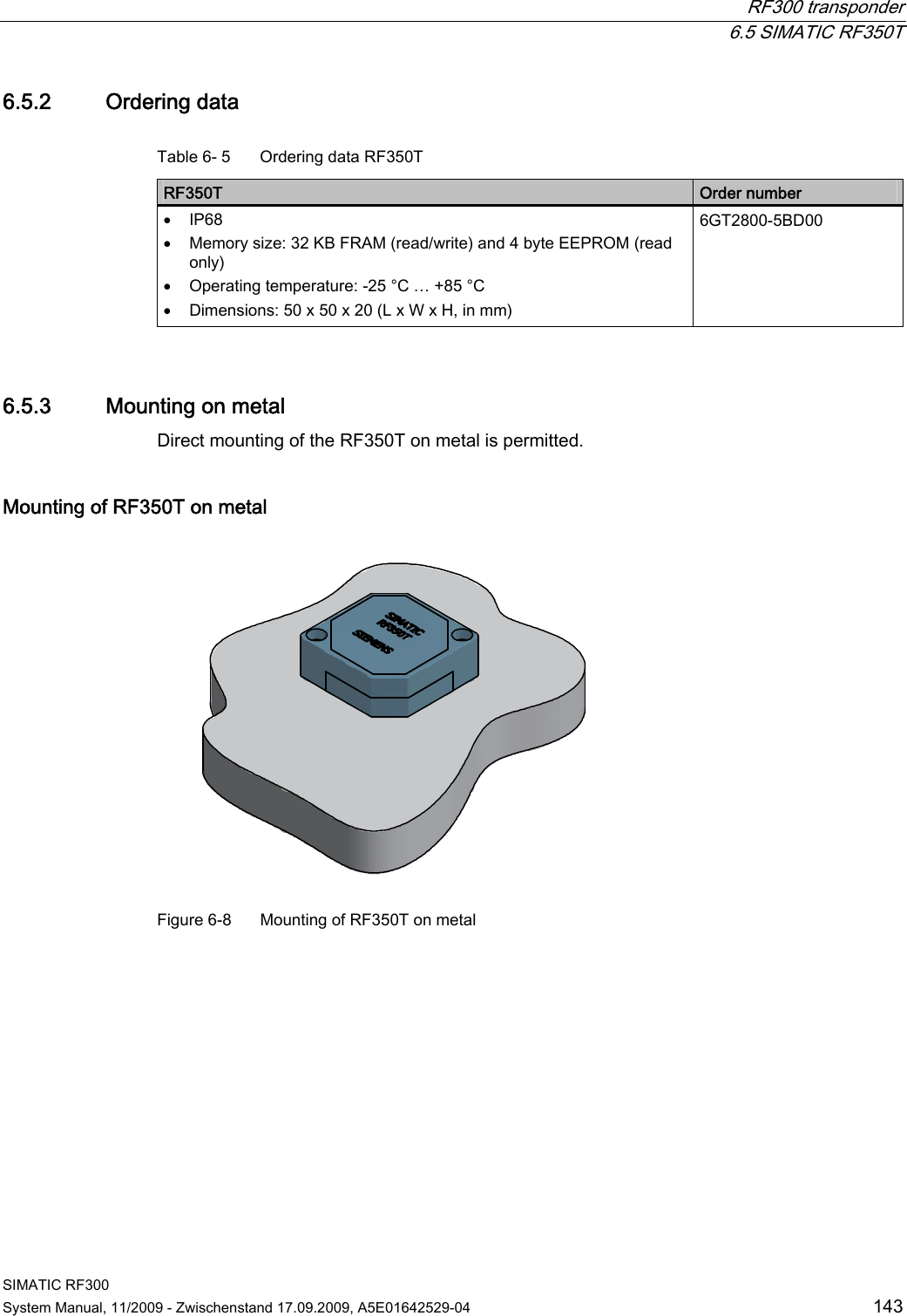
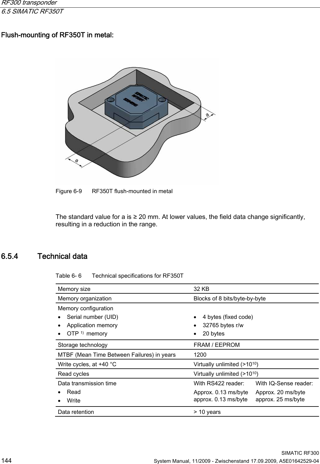
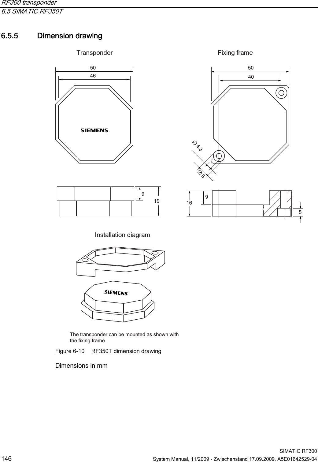
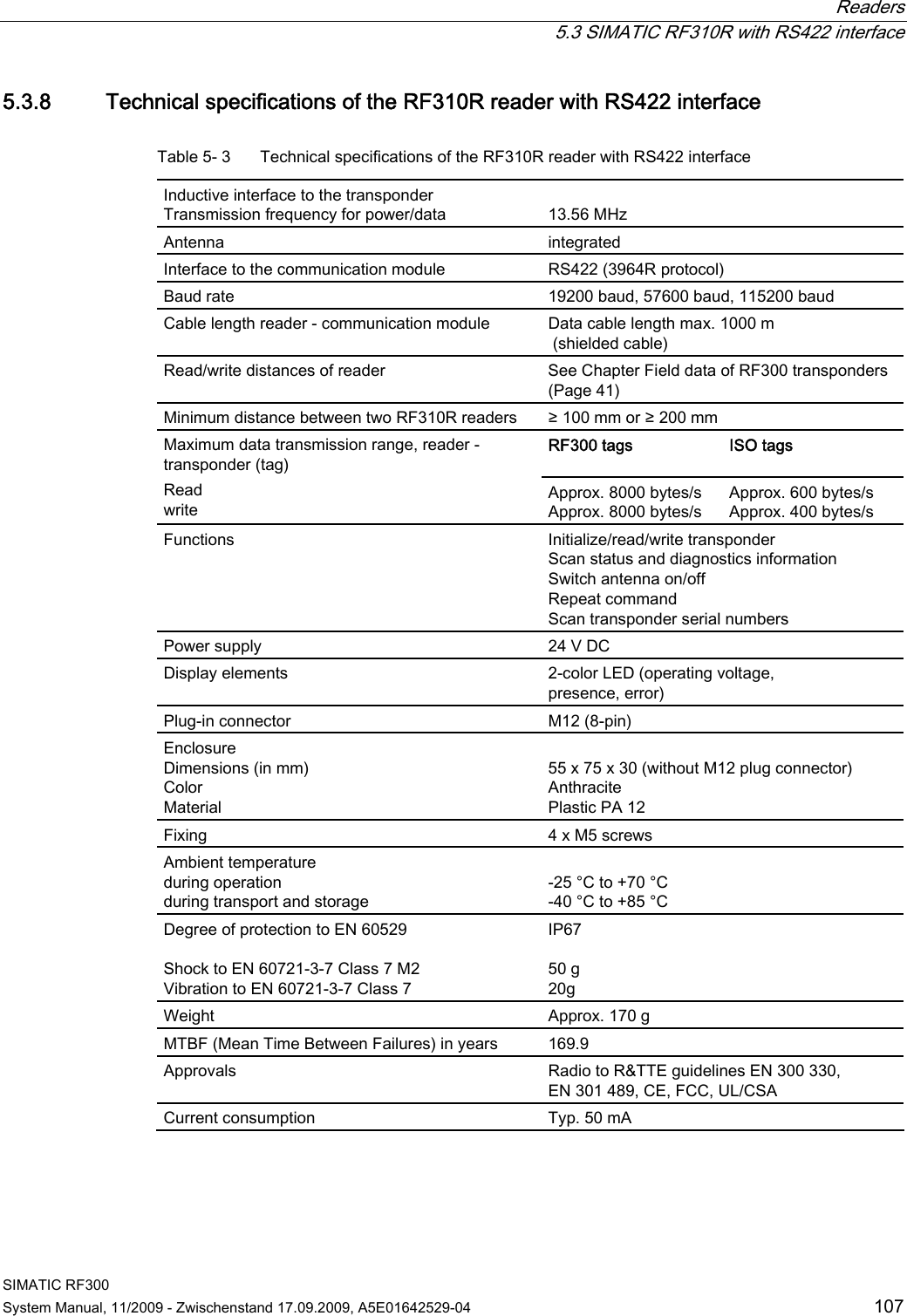
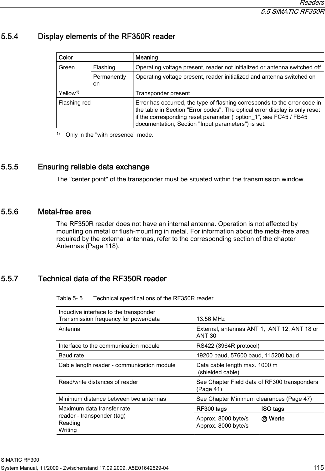
![RF300 transponder 6.5 SIMATIC RF350T SIMATIC RF300 System Manual, 11/2009 - Zwischenstand 17.09.2009, A5E01642529-04 145 Read/write distance Dependent on the reader used [see Chapter Field data of RF300 transponders (Page 41)] Multitag capability max. 4 transponders Recommended spacing from metal can be directly mounted on metal Power supply Inductive, without battery Degree of protection to EN 60529 Shock to EN 60721-3-7 Vibration to EN 60721-3-7 Torsion and bending load IP68 50 g 20 g Not permitted permanently Enclosure dimensions Color Material Fixing 50 x 50 x 20 mm (L x W x H) Anthracite PA12 2 screws M4 Ambient temperature Operation Transport and storage -25 °C to +85 °C -40 °C to +85 °C Weight Approx. 25 g 1) OTP: One Time Programmable](https://usermanual.wiki/Siemens/RF340R01.User-Manual-II/User-Guide-1196868-Page-46.png)