Siemens RF350R01 RFID System User Manual SIMATIC RF300
Siemens AG RFID System SIMATIC RF300
UserManual.wiki
>
Siemens
>
RF350R01 User Manual
>
Users Manual 4 of 4
Contents
1.
Users Manual 1 of 4
2.
Users Manual 2 of 4
3.
Users Manual 3 of 4
4.
Users Manual 4 of 4
Users Manual 4 of 4
Navigation menu
Upload a User Manual
Namespaces
Wiki Guide
HTML
PDF
Info
Views
User Manual
Discussion / Help
Navigation
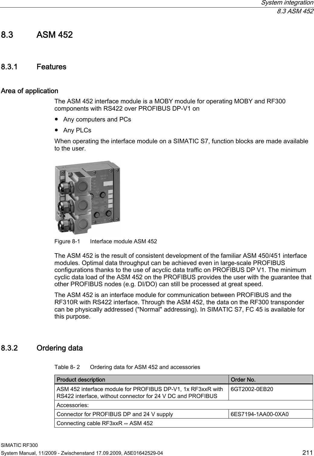
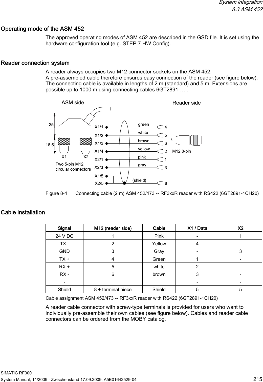
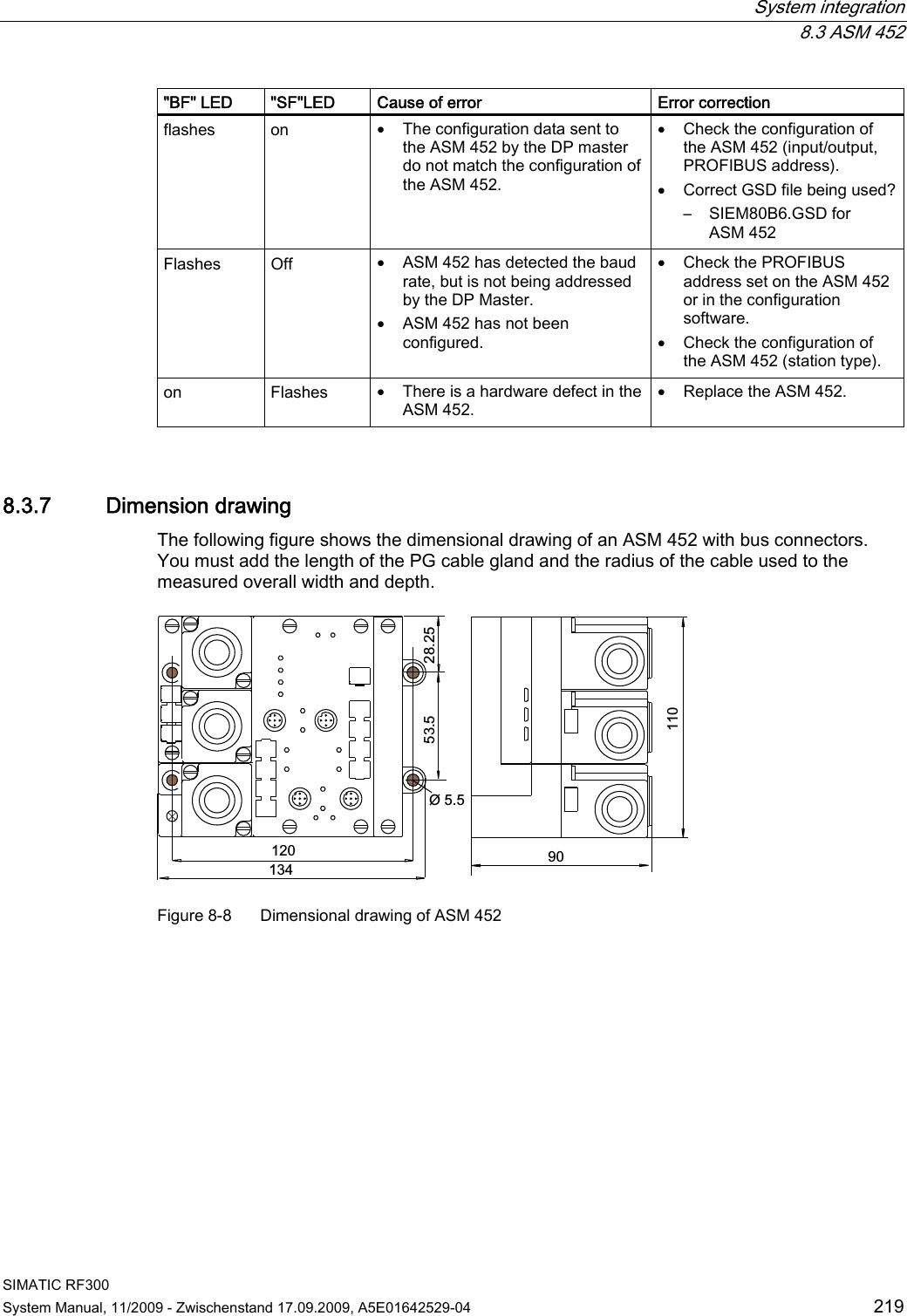
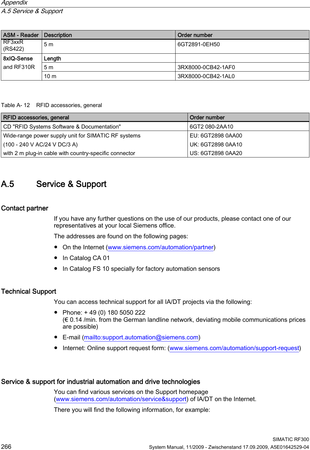
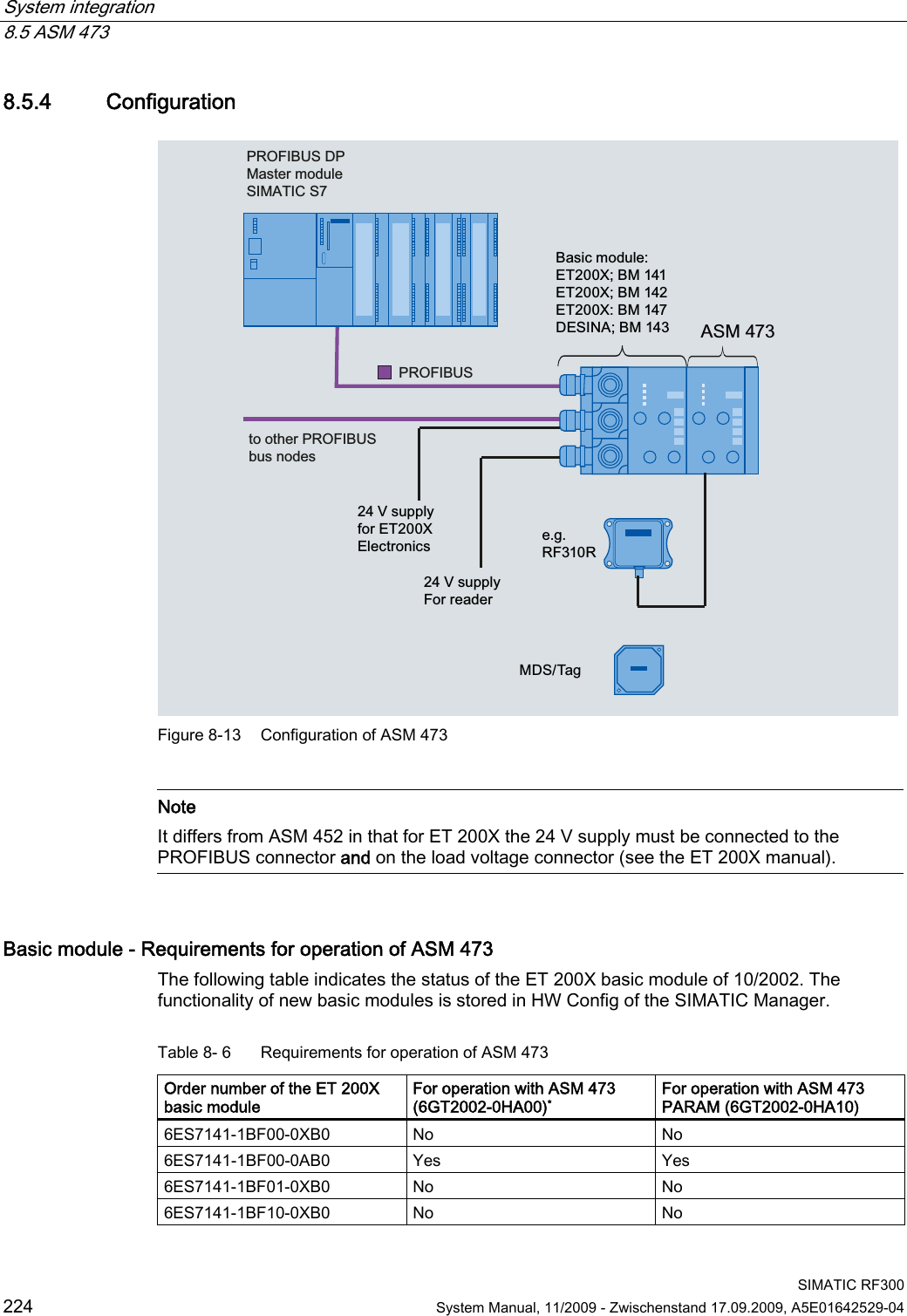
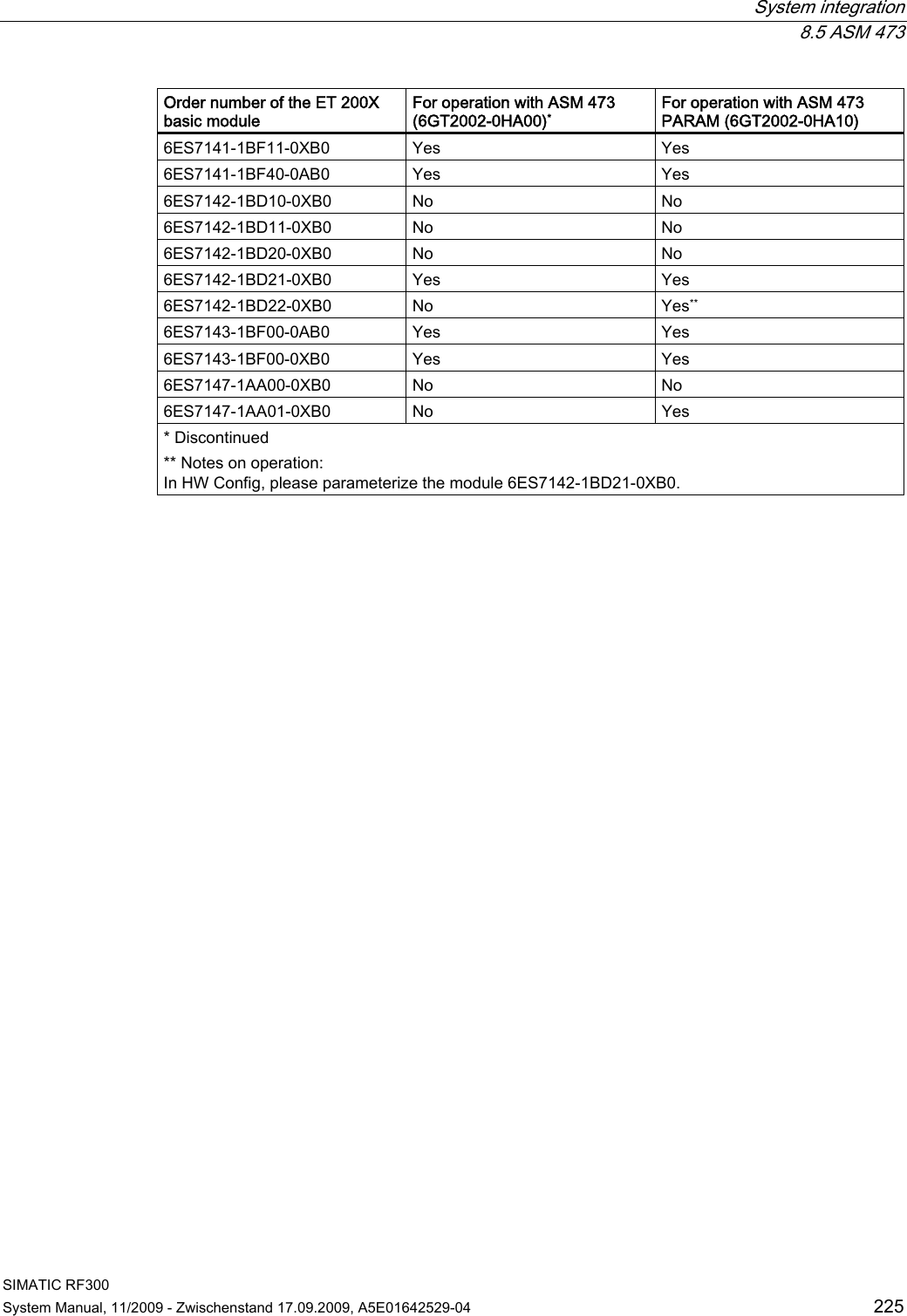
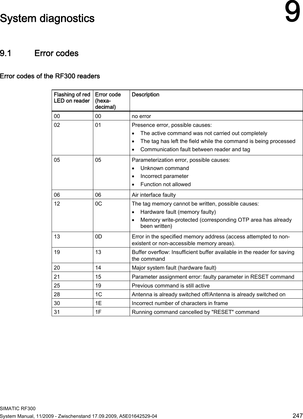
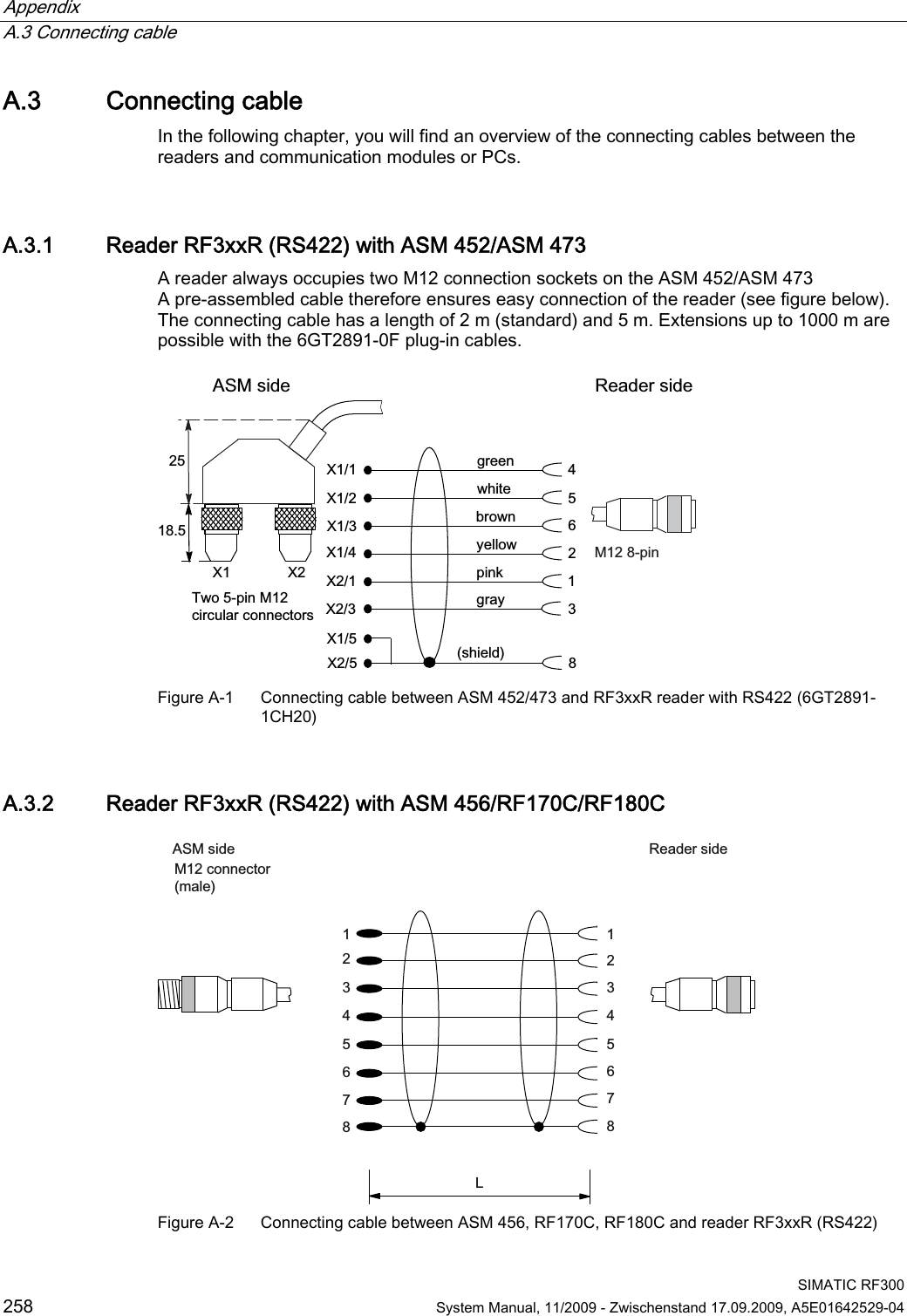
![System integration 8.5 ASM 473 SIMATIC RF300 System Manual, 11/2009 - Zwischenstand 17.09.2009, A5E01642529-04 223 8.5.3 Pin assignment and display elements Pin assignments The figure below illustrates the pin assignment for the read/write device and the display elements. 2))+]+]2))21+]+]+]2));;21SHUP2))21 5[' 7[' 7[' 5[' 3( 9 QF 9 QF 3((5535([IODVKHYHU\V6RFNHW 3LQDVVLJQPHQWUHDGHU/('VIRU352),%86'3*HQHUDOLQGLFDWRUV6)%)219'&DUHORFDWHGRQWKHEDVLFPRGXOHRIWKH(7;/('VIRU02%<5[' 5HDGHUDFWLYHZLWKFRPPDQG35( ,QGLFDWHVWKHSUHVHQFHRIDWUDQVSRQGHU(55 (UURULQGLFDWHGE\IODVKLQJVHTXHQFH7KHIROORZLQJ$60VWDWHVDUHDOVRLQGLFDWHGZLWKWKH/('V35(DQG(55'HVFULSWLRQ&DXVHV5HPHG\+DUGZDUHLVGHIHFWLYH5$0IODVK&KDUJHULVGHIHFWLYHFDQRQO\EHUHSDLUHGLQWKHIDFWRU\)LUPZDUHORDGLQJLVDFWLYHRUQRILUPZDUHGHWHFWHGൺ/RDGILUPZDUHൺ$60PXVWQRWEHVZLWFKHGRIIXQWLOORDGHG)LUPZDUHORDGLQJWHUPLQDWHGZLWKHUURUVൺ5HVWDUWUHTXLUHGൺ/RDGILUPZDUHDJDLQൺ&KHFNXSGDWHILOHV2SHUDWLQJV\VWHPHUURUൺ6ZLWFK$60RU(7;EDVHVWDWLRQ2))21$60KDVERRWHGDQGLVZDLWLQJIRUD5(6(7LQLWBUXQIURPWKHXVHU Figure 8-12 Interfaces and indicators of the ASM 473 for RF300](https://usermanual.wiki/Siemens/RF350R01.Users-Manual-4-of-4/User-Guide-1196229-Page-16.png)

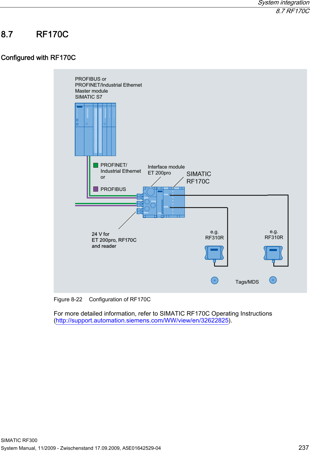
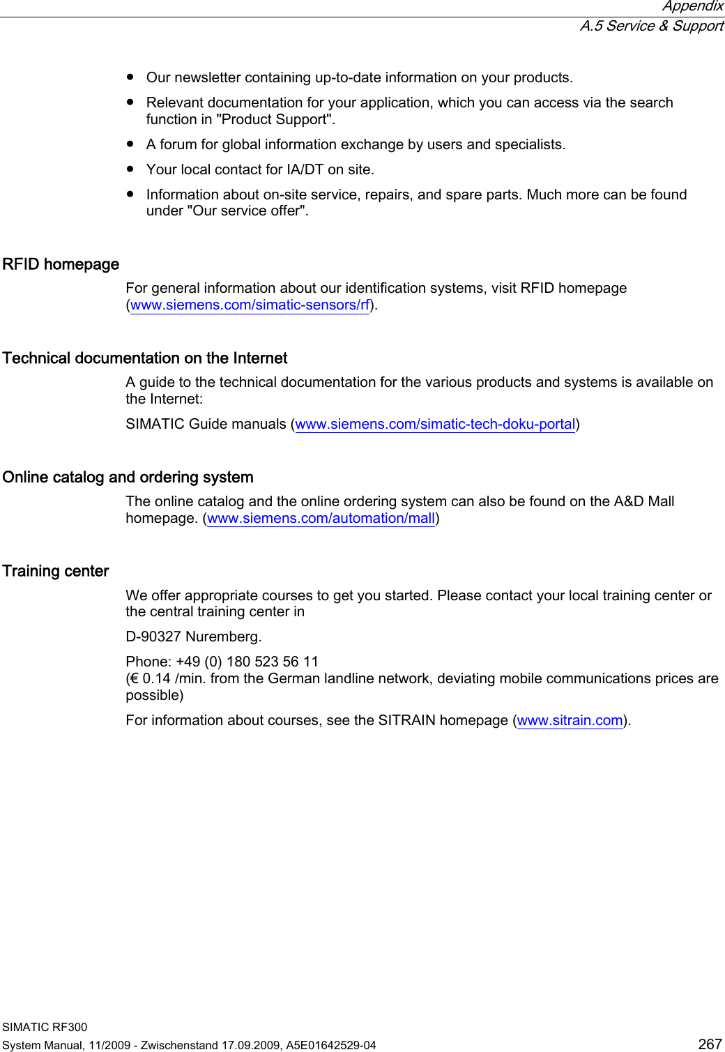
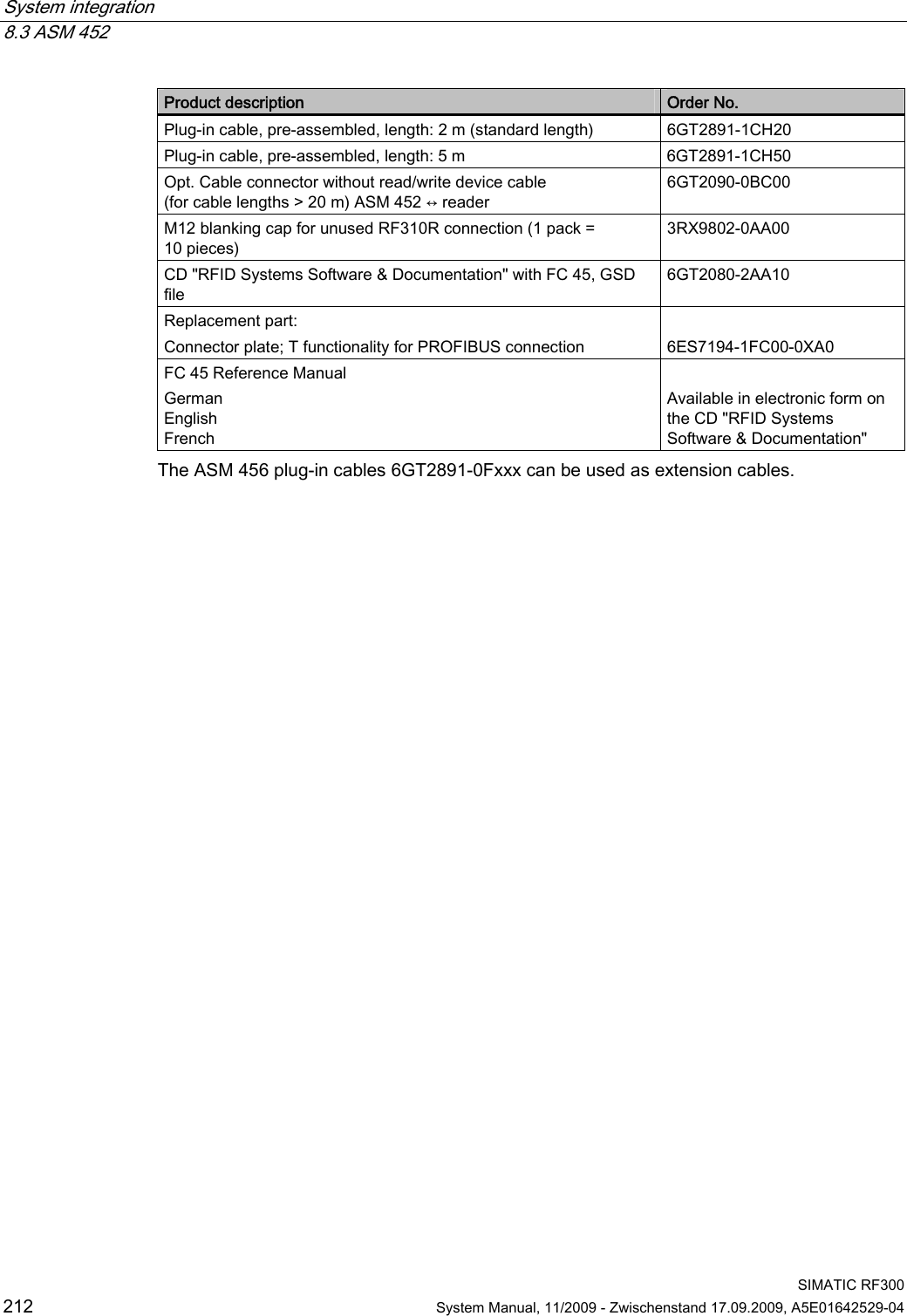
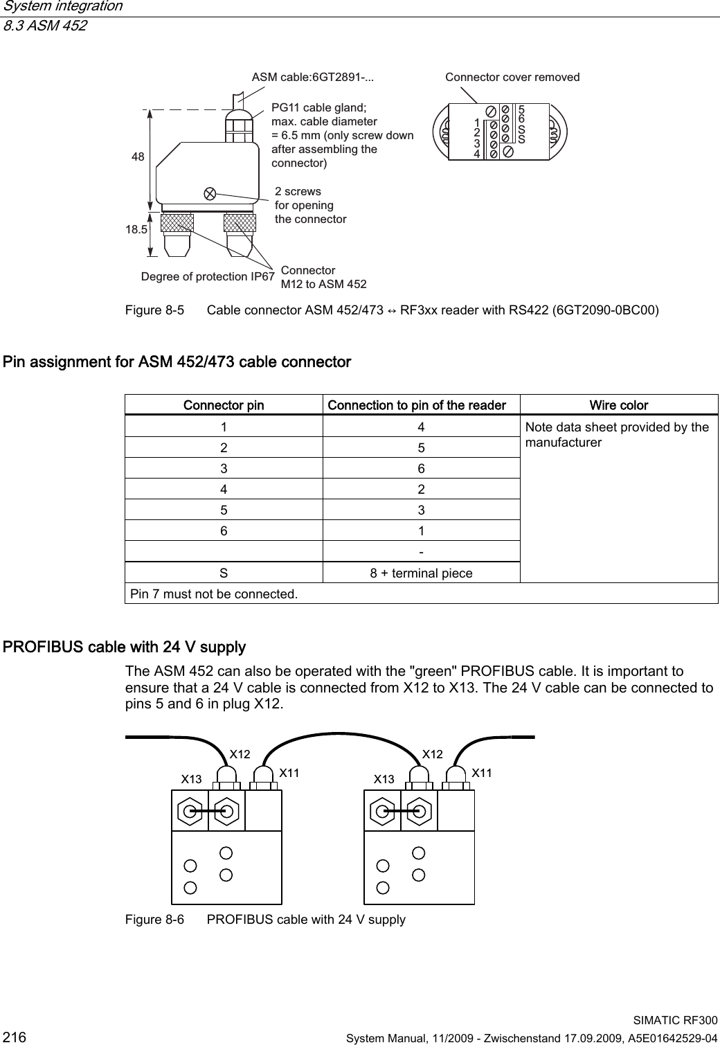
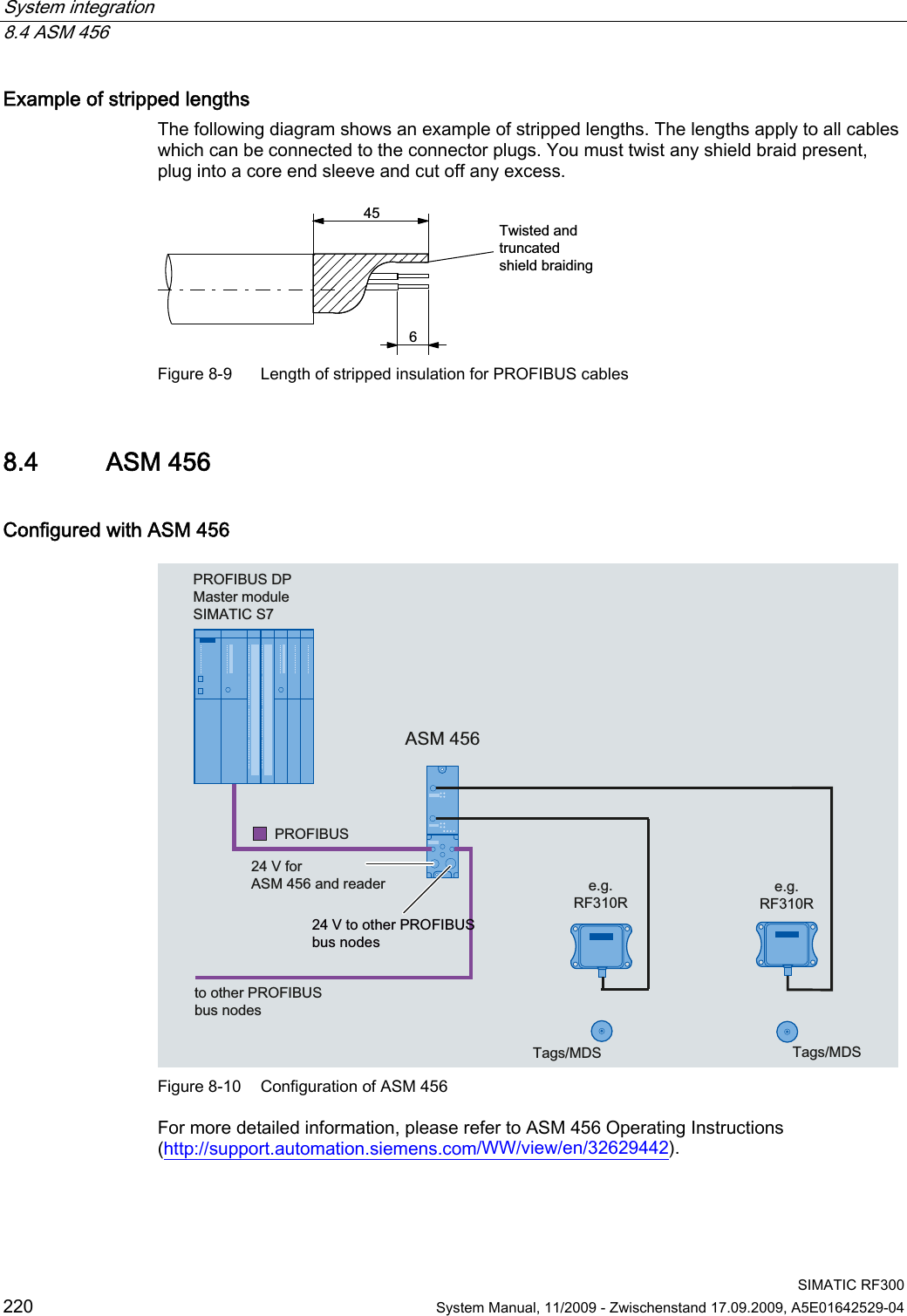
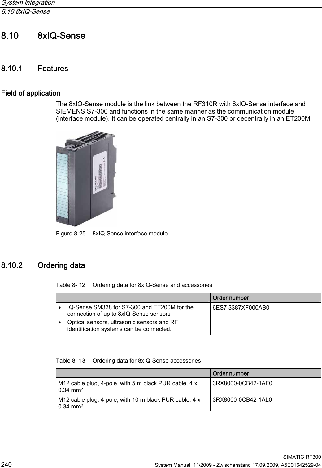
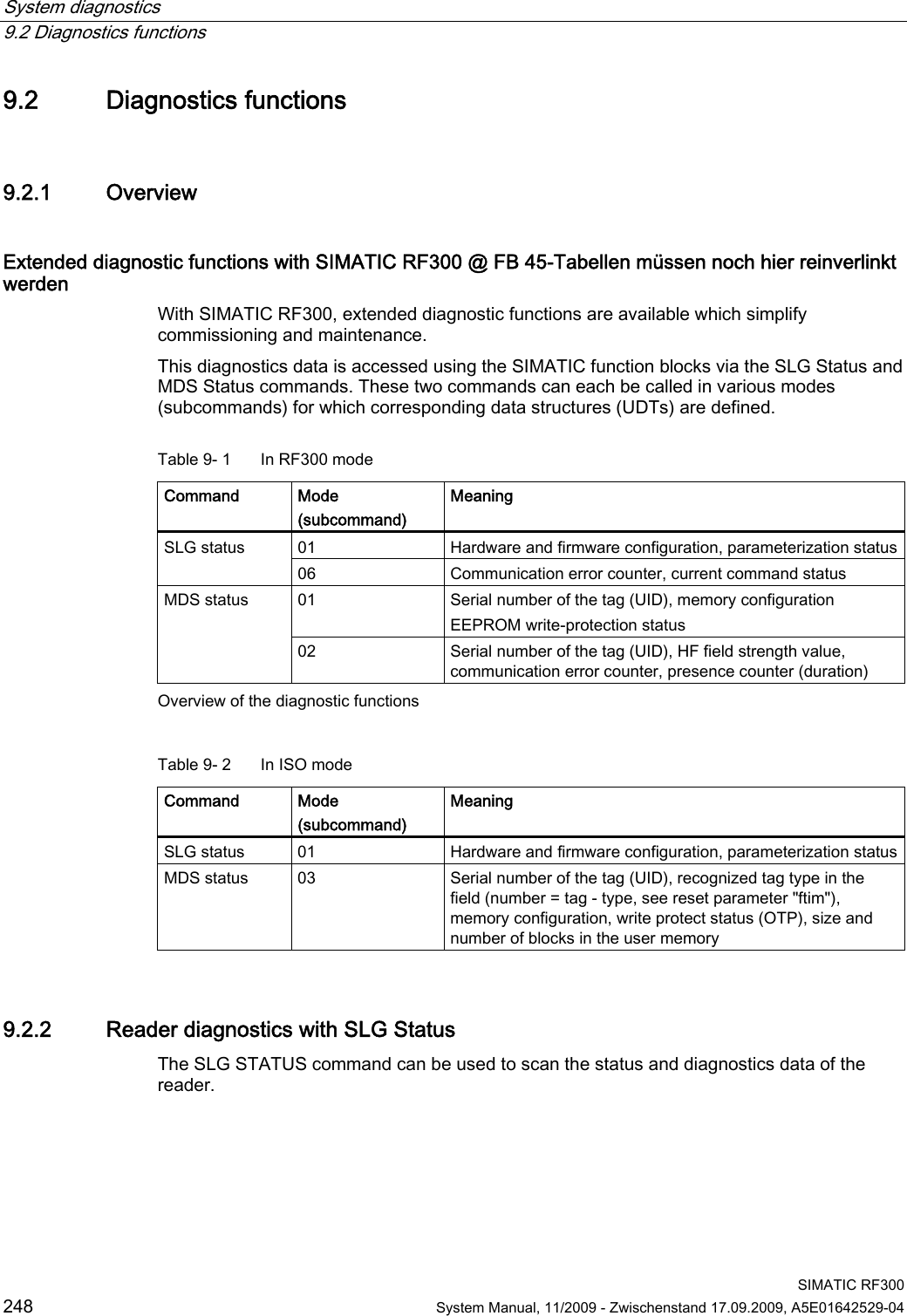
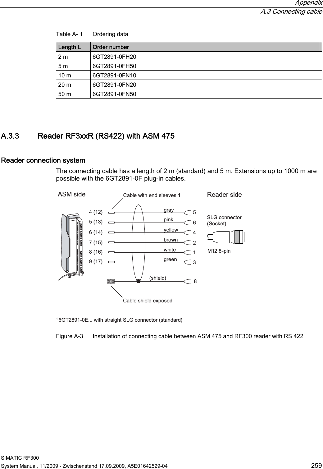
![System integration 8.8 RF180C SIMATIC RF300 238 System Manual, 11/2009 - Zwischenstand 17.09.2009, A5E01642529-04 8.8 RF180C Configured with RF180C ,QGXVWULDO(WKHUQHW352),1(7]%5)5]%5)57DJV0'6352),1(7b,20DVWHUPRGXOH6,0$7,&b69IRU5)&DQGUHDGHUWRRWKHU352),1(7EXVQRGHV6,0$7,&5)&9WRRWKHU352),1(7EXVQRGHV Figure 8-23 Configuration of RF180C For more detailed information, refer to SIMATIC RF180C Operating Instructions (http://support.automation.siemens.com/WW/view/en/30012157).](https://usermanual.wiki/Siemens/RF350R01.Users-Manual-4-of-4/User-Guide-1196229-Page-31.png)
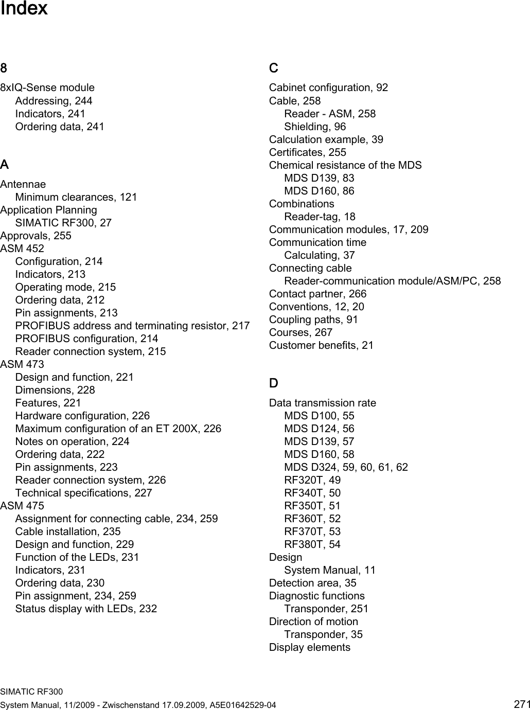
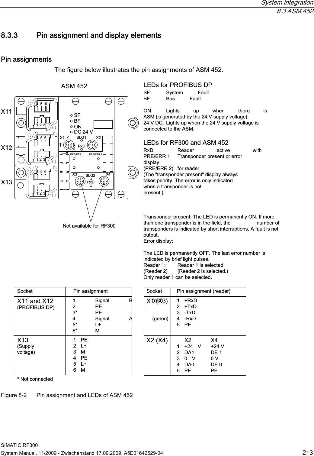
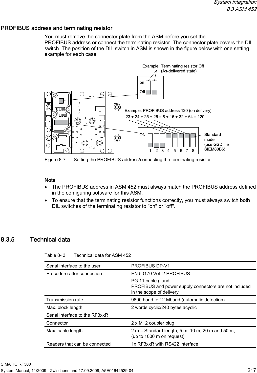
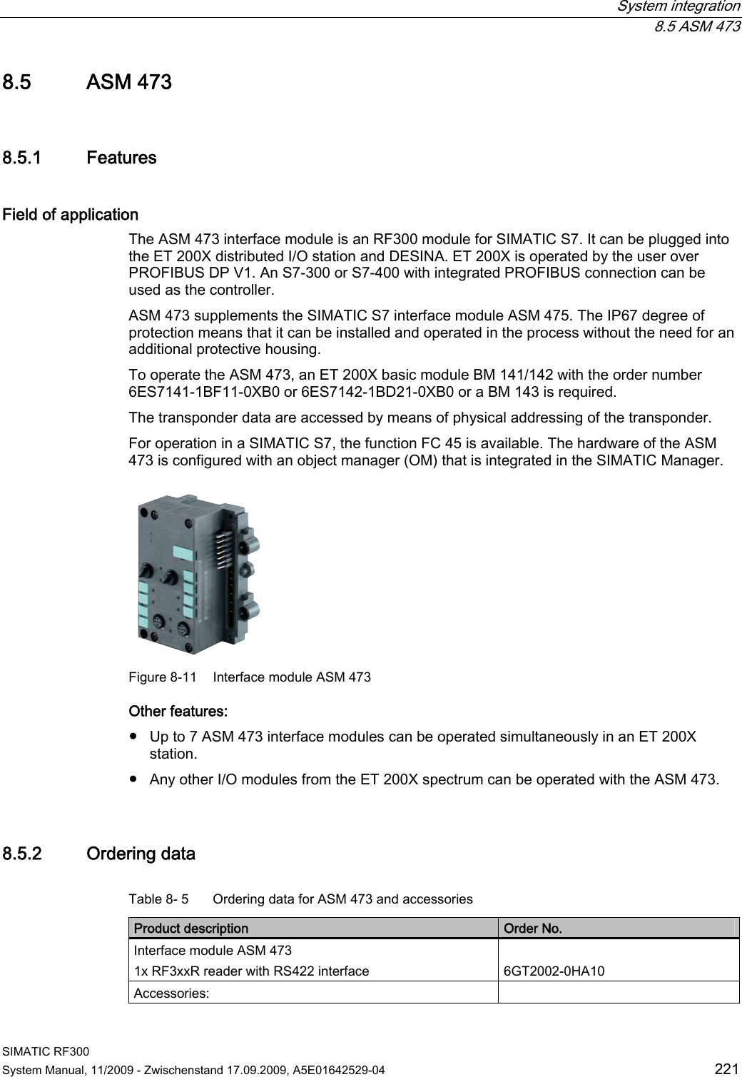
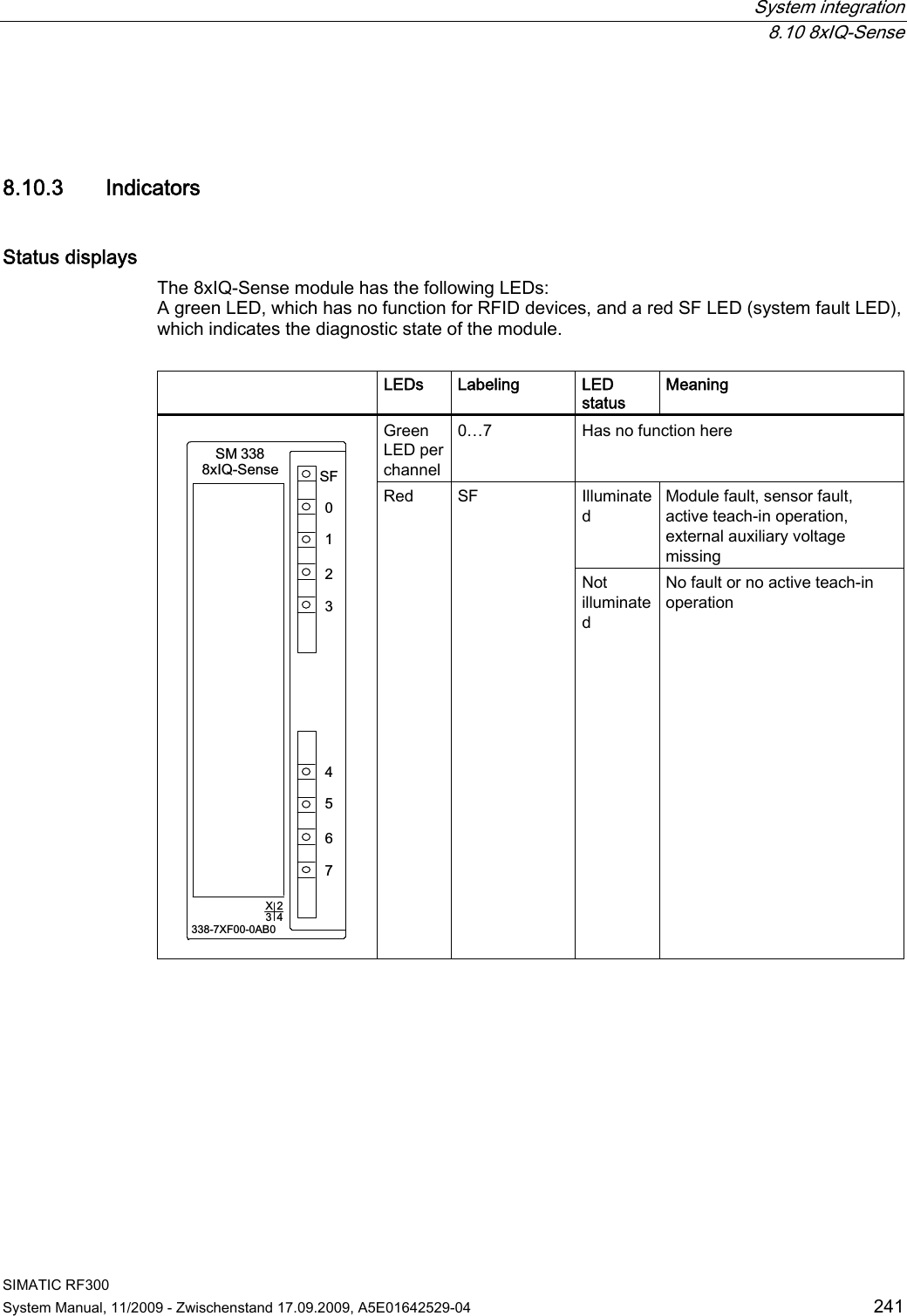
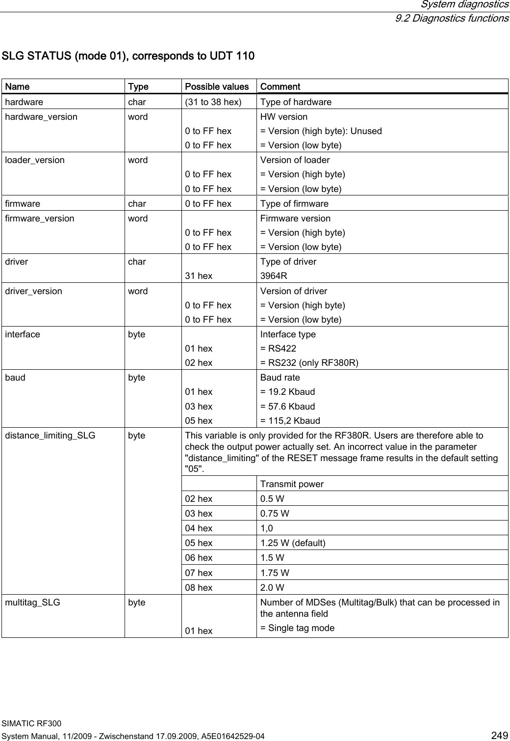
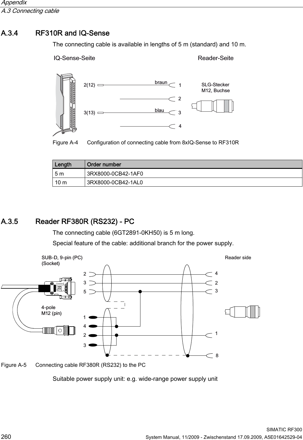
![System integration 8.9 RF182C SIMATIC RF300 System Manual, 11/2009 - Zwischenstand 17.09.2009, A5E01642529-04 239 8.9 RF182C Configuration with RF182C ,QGXVWULDO(WKHUQHW]%5)5]%5)57DJV0'6352),1(7,29IRU5)&DQGUHDGHU7RDGGLWLRQDO352),1(7(WKHUQHWQRGHV6,0$7,&5)&3&PROFINET IOMaster moduleSIMATIC S7 Figure 8-24 Configuration with RF182C For more detailed information, refer to SIMATIC RF182C Operating Instructions (http://support.automation.siemens.com/WW/view/en/38507897).](https://usermanual.wiki/Siemens/RF350R01.Users-Manual-4-of-4/User-Guide-1196229-Page-32.png)
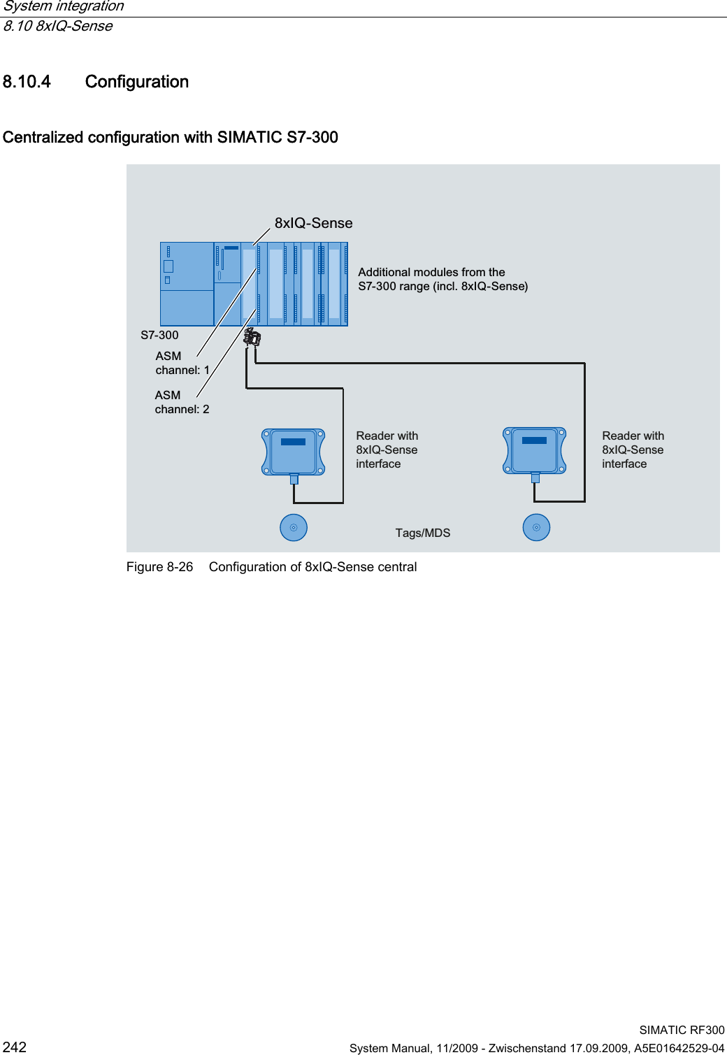
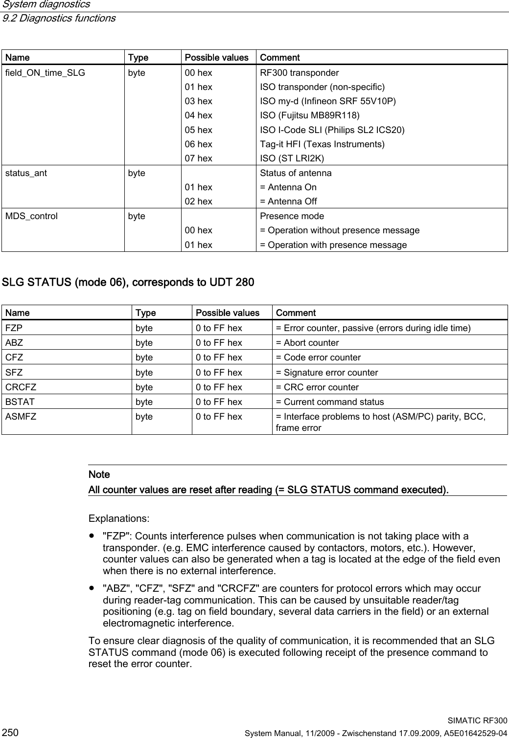
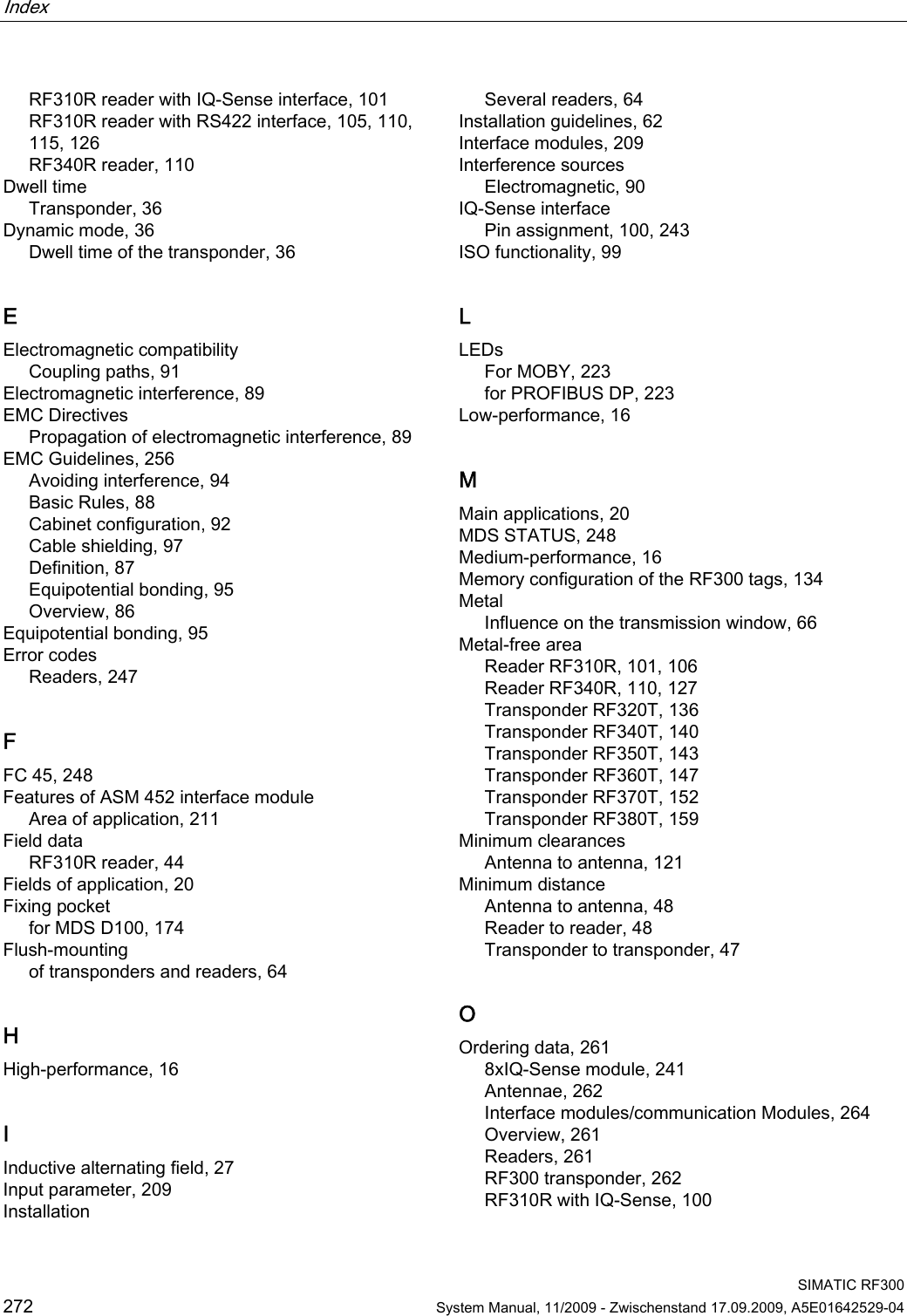
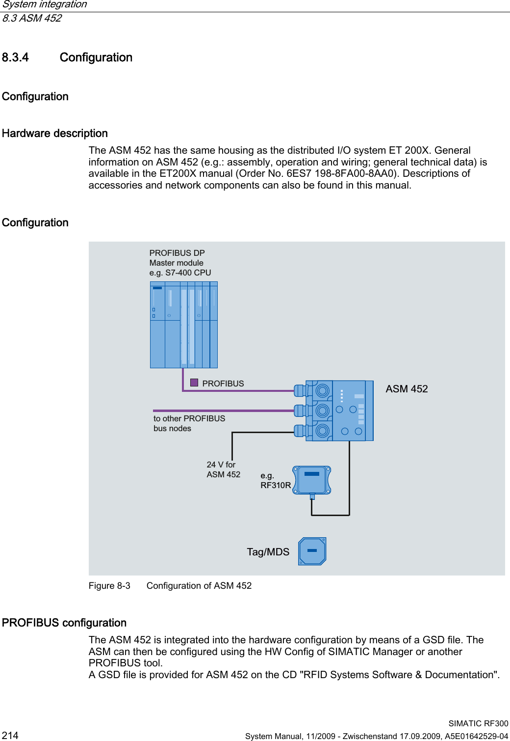
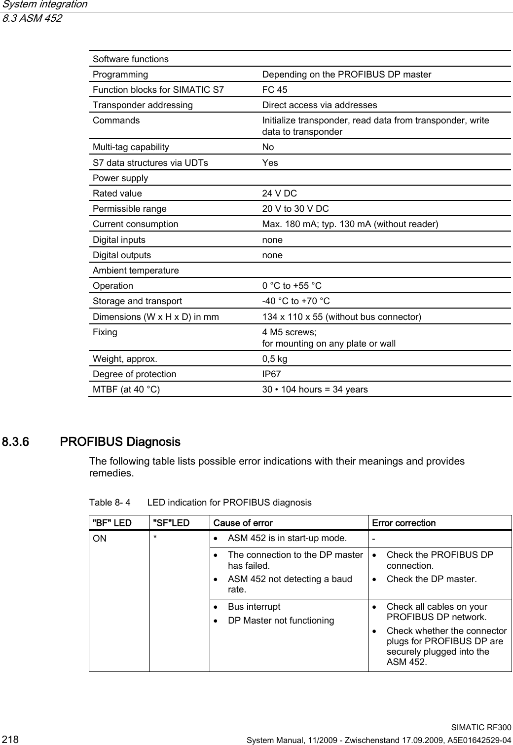
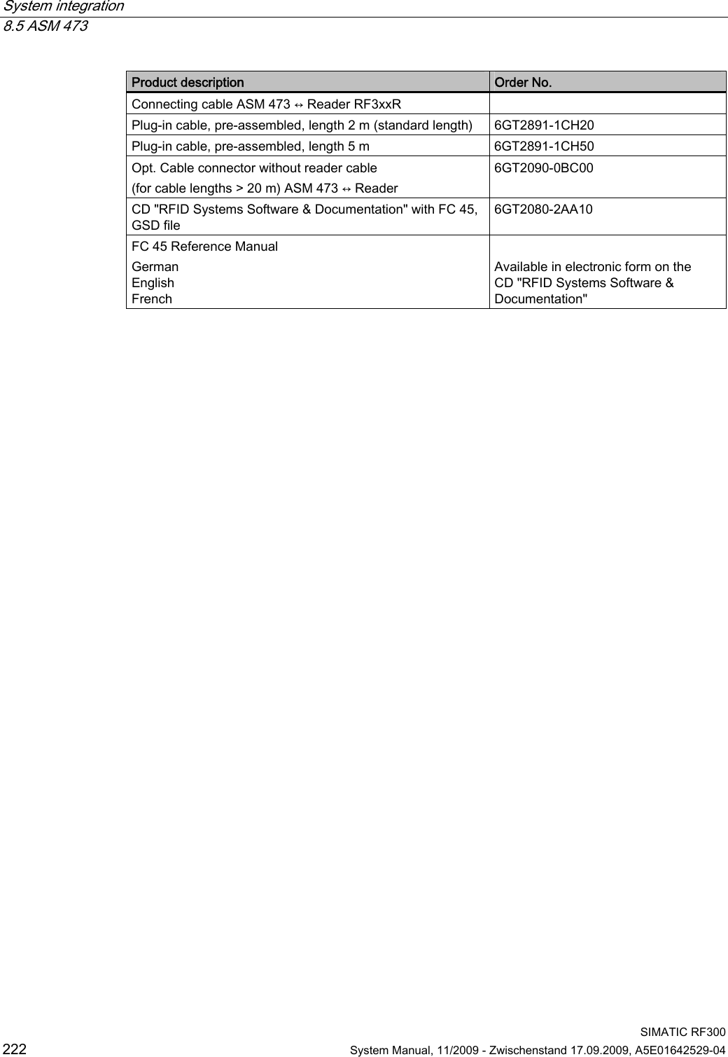
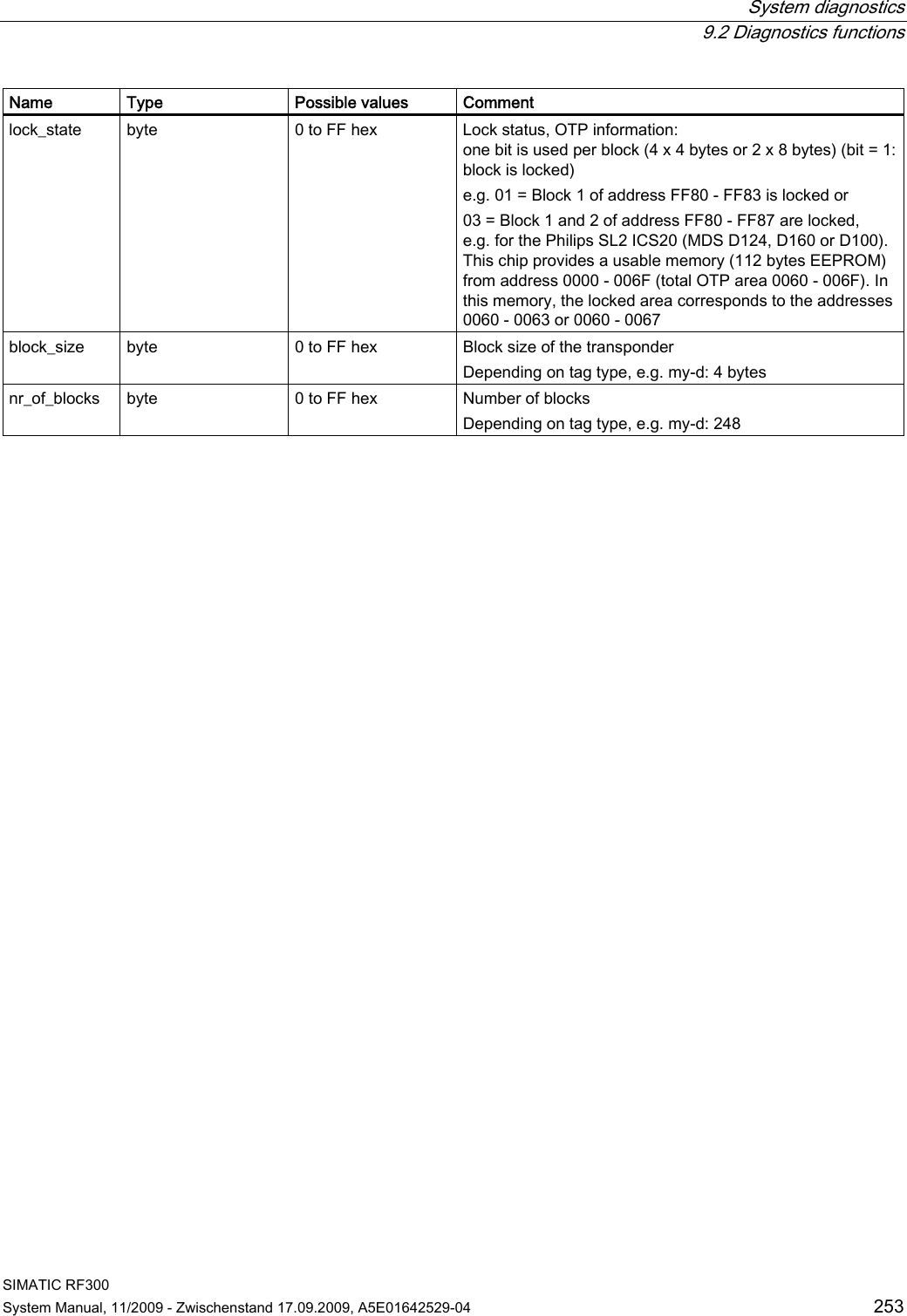
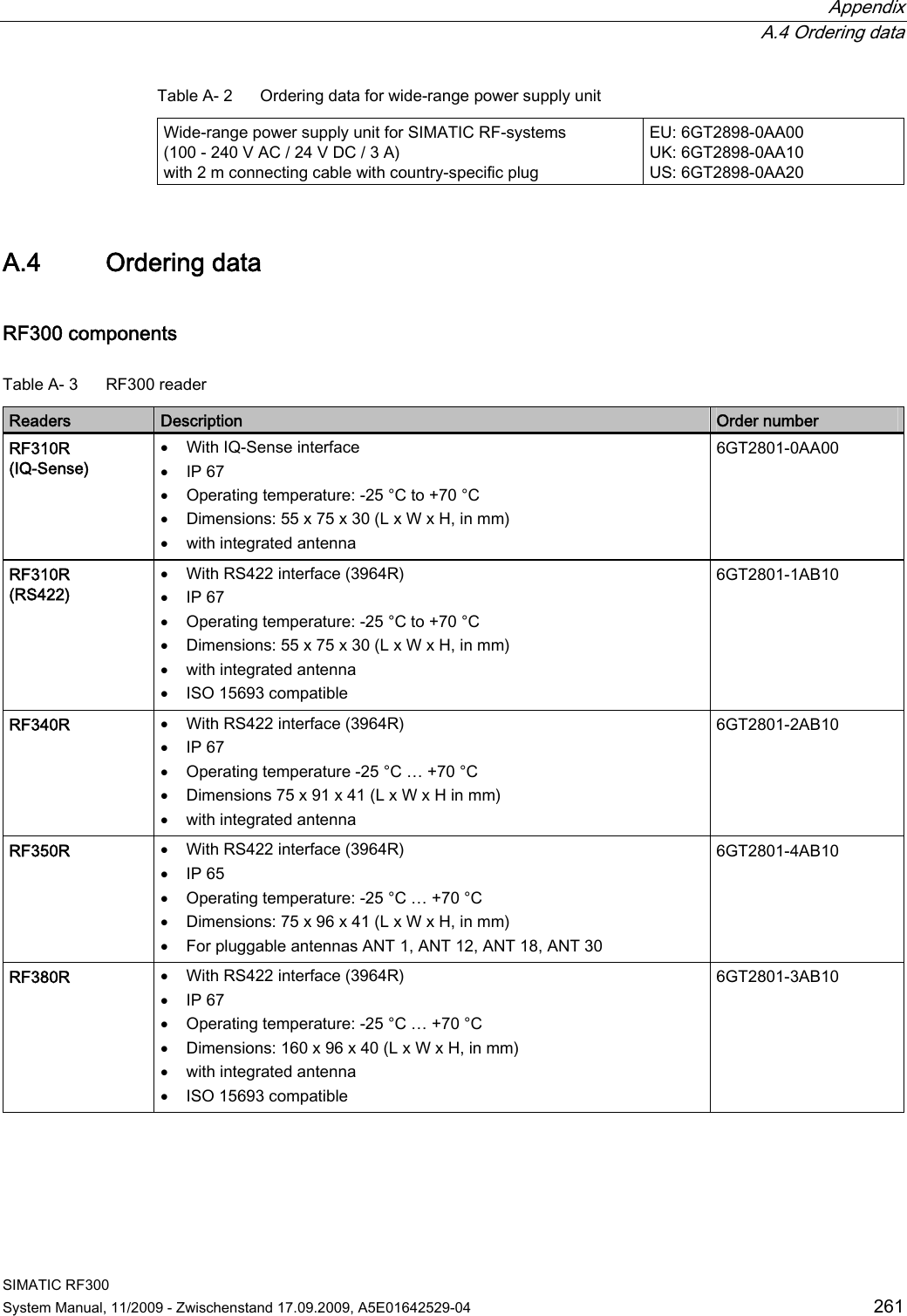
![System diagnostics 9.2 Diagnostics functions SIMATIC RF300 System Manual, 11/2009 - Zwischenstand 17.09.2009, A5E01642529-04 251 The protocol error counters are not mutually independent. If a code error (CFZ) occurs, this will cause a signature (SFZ) or CRC- (CRCFZ) error. ● "BSTAT" is the status for the most recently executed command. A value other than 0 means that the previous command was repeated by the reader due to faults (see above). ● "ASMFZ" signals line-conducted communication interference between the communication module (ASM) and the reader. Faults of this type can be caused by contact problems on the connector or the cable connection. 9.2.3 Transponder diagnostics with MDS Status The MDS STATUS command can be used to scan the status and diagnostics data of the transponder that is located within the antenna field. MDS Status (mode 01), corresponds to UDT 260, only for RF300 tags Name Type Possible values Comment UID array[1…8] byte 0000000055555555 hex to 00000000 FFFFFFFF hex Unique identifier = b0-31: 4 byte TAG ID, b32-63: 0 MDS_type byte 01 hex 02 hex 03 hex 04 hex Tag memory configuration = Transponder without FRAM = Transponder with FRAM 8 KB = Transponder with FRAM 32 KB = Transponder with FRAM 32 KB Lock_state byte 0 to FF hex EEPROM write protection status (use graphic from UDT260 here) MDS Status (mode 02), corresponds to UDT 270, only for RF300 tags Name Type Possible values Comment UID array[1…8] byte 0000000055555555 hex to 00000000FFFFFFFF hex Unique identifier = b0-31: 4 byte TAG ID, b32-63: 0 LFD byte 0 to FF hex = Value for field strength determined in the tag FZP byte 0 to FF hex = Error counter (passive) ➙ errors during idle time FZA byte 0 to FF hex = Error counter (active) ANWZ byte 0 to FF hex = Presence counter](https://usermanual.wiki/Siemens/RF350R01.Users-Manual-4-of-4/User-Guide-1196229-Page-44.png)
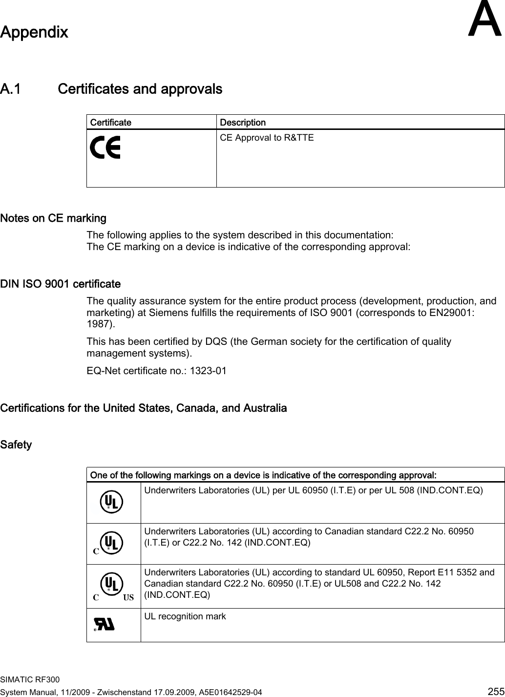
![System diagnostics 9.2 Diagnostics functions SIMATIC RF300 252 System Manual, 11/2009 - Zwischenstand 17.09.2009, A5E01642529-04 Note All counter values are reset when the tag exits the field or when the antenna is switched off. Explanations: ● "LFD" is a value for the field strength that is determined in the transponder. The lower the value, the higher the field strength. ● "FZP" counts fault pulses when communication with a transponder is not taking place (e.g. electromagnetic interference caused by contactors, motors, etc.). Counter values can also be generated when a transponder is located at the edge of the field even when there is no external interference. ● "FZA" counts errors that can occur during reader-to-transponder communication. This can be caused by unsuitable reader/transponder positioning (e.g. transponder on field boundary, several data carriers in the field) or external electromagnetic interference. ● "ANWZ" is the value for the time that the transponder remains in the field before the MDS STATUS command (mode 02) is executed. A time step is 10 ms. The maximum time that can be recorded is therefore 2.5 s. MDS STATUS for ISO mode (mode 03) corresponds to UDT 230 Table 9- 3 MDS STATUS for ISO mode Name Type Possible values Comment UID array[1…8] byte 000000000 0000000 hex to FFFFFFFF FFFFFFFF hex Unique identifier =8 byte UID, MSB first MDS_type byte 01 hex 03 hex 04 hex 05 hex 06 hex 07 hex Tag type (vendor, identification) = ISO general (non-specific or unknown) = my-d (Infineon) = MB89R118 (Fujitsu) = I-Code SLI (NXP) = Tag-it HFI (Texas Instruments) = LRI2K (ST) IC_version byte 0 to FF hex Chip version size byte 0 to FF hex Memory size in bytes Depending on tag type, e.g. my-d: 992 bytes](https://usermanual.wiki/Siemens/RF350R01.Users-Manual-4-of-4/User-Guide-1196229-Page-45.png)
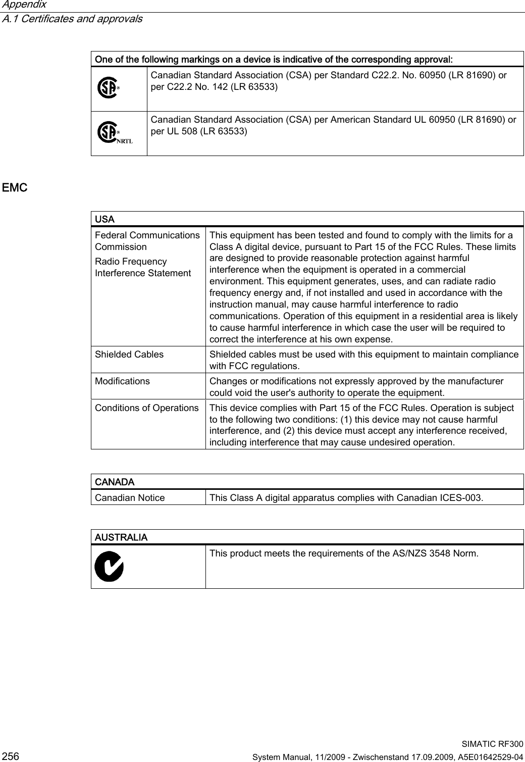
![Appendix A.4 Ordering data SIMATIC RF300 System Manual, 11/2009 - Zwischenstand 17.09.2009, A5E01642529-04 263 RF300 transponder Description Order number RF370T (64 KB FRAM) IP68 Memory size: 64 KB FRAM Operating temperature: -25 °C to +85 °C Dimensions: 75 x 75 x 40 (L x W x H, in mm) 6GT2800-6BE00 RF380T IP68 Memory size 32 KB FRAM (read/write) and 4 byte EEPROM Operating temperature -25 … +200 °C (cyclic) Dimensions: 114 x 83 (Ø x H in mm) 6GT2800-5DA00 Table A- 6 ISO transponder ISO transponder Description Order number MDS D100 IP68 Memory size: 112 byte EEPROM Operating temperature: -25 … +80 °C Dimensions: 85.6 x 54 x 0.9 (L x W x H, in mm) ISO card 6GT2600-0AD10 MDS D124 IP67 Memory size: 112 byte EEPROM user memory Operating temperature: -25 … +125 °C Dimensions: 27 mm x 4 mm (Ø x H in mm) 6GT2600-0AC00 MDS D139 IP68 Memory size: 112-byte user memory Operating temperature: up to +200 °C/+220 °C [heat-resistant (r/w)] Dimensions: 85 x 15 (Ø x H in mm) 6GT2600-0AA10 MDS D160 IP68 (24 hours, 2 m, +20 °C) Memory size: 112 byte user memory Operating temperature: -25 °C...+70 °C Dimensions: 16 x 3 ±0.1 (Ø x H in mm) Laundry tag for cyclical applications (r/w) 6GT2600-0AB10 MDS D324 IP67 Memory size: 992 byte EEPROM user memory Operating temperature: -25 °C...+125 °C Dimensions: 27 x 4 (Ø x H in mm) 6GT2600-3AC00 MDS D421 IP67/x9K Memory size: 2000 byte user memory Operating temperature: –25 °C to +85 °C Dimensions: 10 x 4.5 (Ø x H in mm) 6GT2600-4AE00 MDS D424 IP67 Memory size: 992 byte EEPROM user memory Operating temperature: -25 °C ...+125 °C Dimensions: 27 x 4 (Ø x H in mm) 6GT2600-4AC00](https://usermanual.wiki/Siemens/RF350R01.Users-Manual-4-of-4/User-Guide-1196229-Page-56.png)
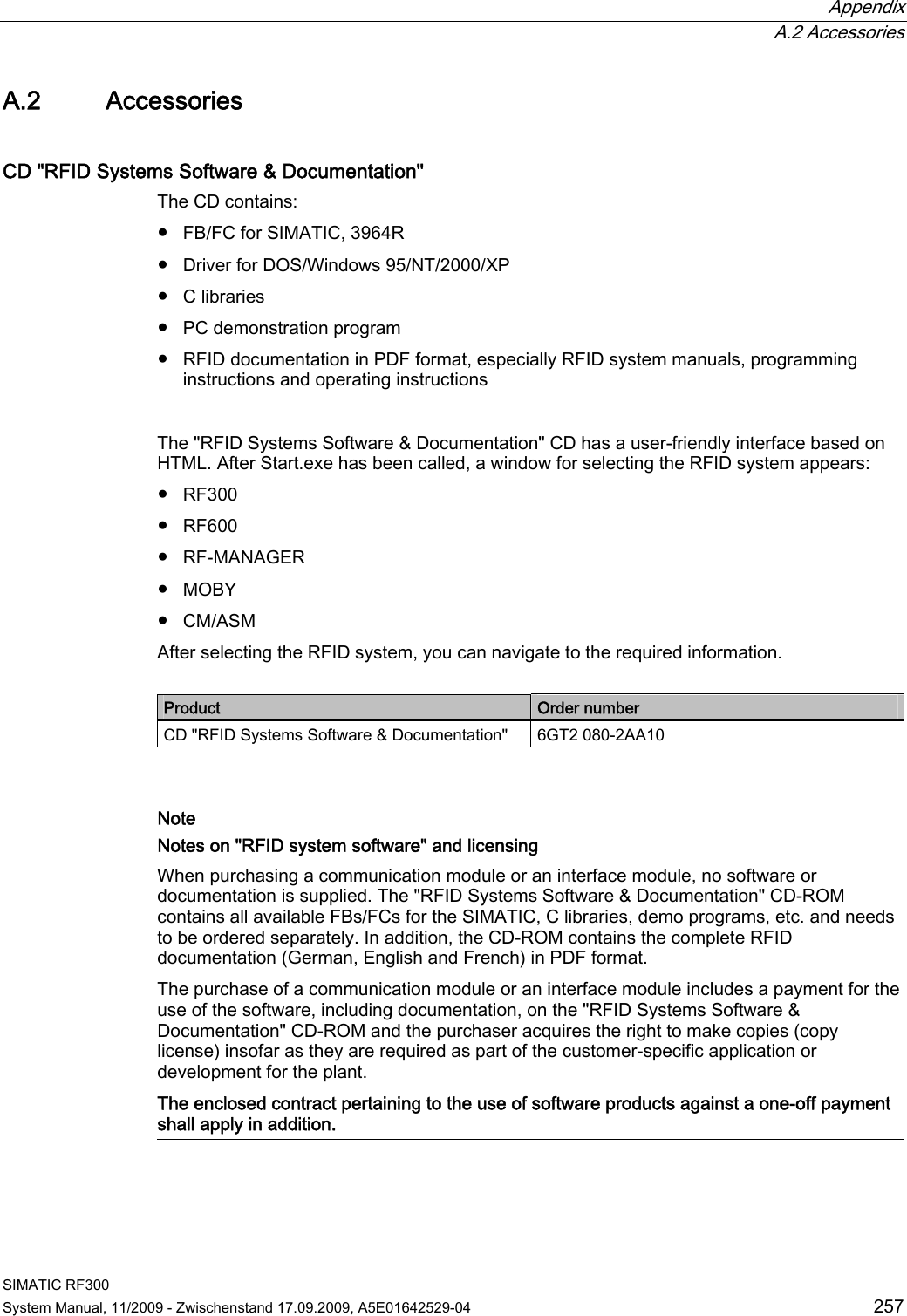
![Appendix A.4 Ordering data SIMATIC RF300 System Manual, 11/2009 - Zwischenstand 17.09.2009, A5E01642529-04 265 Accessories Table A- 8 Accessories for RF300 reader Readers Accessories Order number RF380R Connecting cable RS232 to PC 6GT2891-0KH50 Table A- 9 Accessories for RF300 tags Tag Accessories Order number Spacers 6GT2190-0AA00 RF360T Fixing pocket 6GT2190-0AB00 Holder (short version) 6GT2090-0QA00 Holder (long version) 6GT2090-0QA00-0AX3 Covering hood 6GT2090-0QB00 RF380T Universal holder 6GT2590-0QA00 Table A- 10 Accessories for ISO tags MDS Accessories Order number Spacers 6GT2190-0AA00 Fixing pocket 6GT2190-0AB00 MDS D100 Fixing pocket (cannot be mounted directly on metal) 6GT2390-0AA00 MDS D139 Spacer [85 mm x 30 mm (Ø x H in mm)] 6GT2690-0AA00 Table A- 11 Connecting cable accessory - ASM/communication module to reader ASM - Reader Description Order number Length 2 m 6GT2891-1CH20 ASM 452/ ASM 473 and reader RF3xxR with RS422 5 m 6GT2891-1CH50 Length 2 m 6GT2891-0FH20 5 m 6GT2891-0FH50 10 m 6GT2891-0FN10 20 m 6GT2891-0FN20 ASM 456/RF170C/ RF180C and reader RF3xxR (RS422) 50 m 6GT2891-0FN50 Length ASM 475 and reader 2 m 6GT2891-0EH20](https://usermanual.wiki/Siemens/RF350R01.Users-Manual-4-of-4/User-Guide-1196229-Page-58.png)