Siemens RF350R01 RFID System User Manual SIMATIC RF300
Siemens AG RFID System SIMATIC RF300
Siemens >
Contents
- 1. Users Manual 1 of 4
- 2. Users Manual 2 of 4
- 3. Users Manual 3 of 4
- 4. Users Manual 4 of 4
Users Manual 4 of 4

SIMATIC RF300
System Manual, 11/2009 - Zwischenstand 17.09.2009, A5E01642529-04 209
System integration 8
The communication modules (interface modules) are links between the RFID components
(reader and transponder) and the higher-level controllers (e.g. SIMATIC S7), or PCs or
computers.
8.2 Introduction
RF310R, RF340R, RF350R and RF380R readers are connected to the controller via the
following interface/communication modules:
● ASM 452
● ASM 456
● ASM 473
● ASM 475
● RF170C
● RF180C
● RF182C
● 8xIQ-Sense
Function blocks, interface modules/communication modules and readers
Function blocks are used for integration into the SIMATIC. Using these, the input parameters
are transferred to the reader using the "init_run"(RESET) command.
You can find more detailed information on the software parameterization in Product
Information "FB 45 and FC 45 input parameters for RF300 and ISO transponders"
(http://support.automation.siemens.com/WW/view/en/33315697) or the Function Manual FB
45 (http://support.automation.siemens.com/WW/view/en/21738808) from edition A3
onwards.

System integration
8.2 Introduction
SIMATIC RF300
210 System Manual, 11/2009 - Zwischenstand 17.09.2009, A5E01642529-04
Interface modules/communication modules and function blocks
The following table shows the most important features of the interface
modules/communication modules, as well as the compatible function blocks.
Table 8- 1 Overview of interface modules/communication modules
ASM/
communicatio
n module
Interfaces to
the
application
(PLC)
Interfaces to the
reader
Function
blocks
Reader
connections
Dimensions
(W x H x D) in
mm
Temperatu
re range
Degree
of
protectio
n
ASM 452 PROFIBUS
DP-V1
2 x 8-pin socket,
M12
FC 45 1 134 x 110 x 55 0 °C to +55
°C
IP67
ASM 456 PROFIBUS
DP-V1
2 x 8-pin socket,
M12
FB 45
FC 55
FC 56
2 (parallel) * 60 x 210 x 54
or 79
0 °C to
+55 °C
IP67
ASM 473 PROFIBUS
DP-V1
2 x 8-pin socket,
M12
FC 45
FB 45
FC 55
1 87 x 110 x 55 0 °C to +55
°C
IP67
ASM 475 S7-300
(central),
ET200M
(PROFIBUS)
Via screw
terminals in front
connector
FC 45
FB 45
FC 55
2 40 x 125 x 120 0 °C to +60
°C
IP20
SIMATIC
RF170C
PROFIBUS
DP-V1
PROFINET IO
2 x 8-pin socket,
M12
FB 45
FC 55
2 (parallel) * 90 x 130 x 60 -25 °C to
+55° C
IP67
SIMATIC
RF180C
PROFINET IO 2 x 8-pin socket,
M12
FB 45 2 (parallel) * 60 x 210 54
0 °C to
+60° C
IP67
SIMATIC
RF182C
PROFINET IO 2 x 8-pin socket,
M12
__ 2 (parallel) * 60 x 210 x 30 0 to +60 °C IP67
8xIQ-Sense 8xIQ-Sense Via screw
terminals in front
connector
FC 35 2 (parallel) * 40 x 125 x 120 0 °C to +60
°C
IP20
*) If 2 readers are used on one ASM, the following restrictions apply:
The maximum operating temperature is 35 °C
The input voltage is 24 V ±10%
Current consumption ≤ 425 mA per reader
System integration
8.3 ASM 452
SIMATIC RF300
System Manual, 11/2009 - Zwischenstand 17.09.2009, A5E01642529-04 211
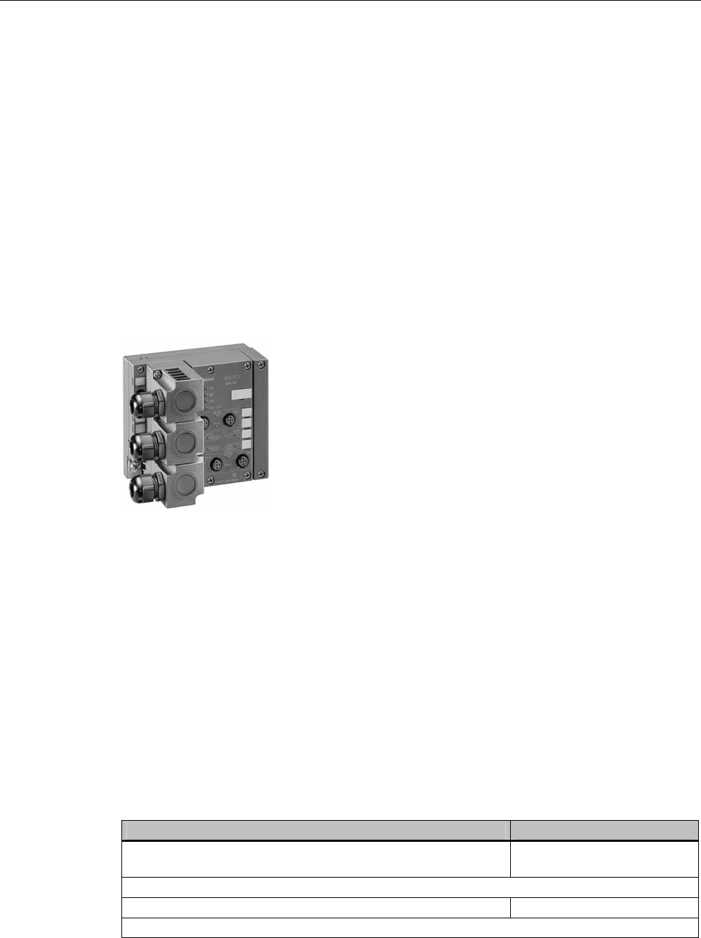
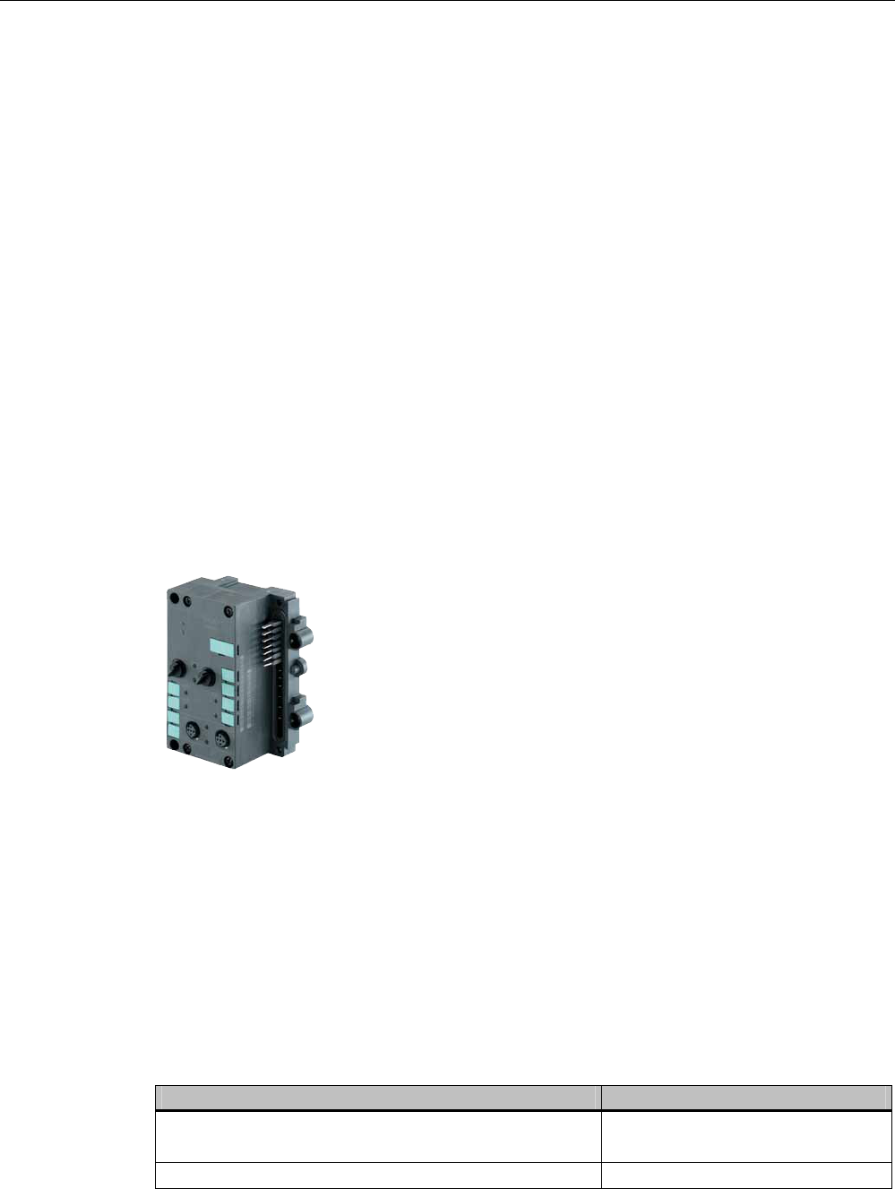
8.3 ASM 452
8.3.1 Features
Area of application
The ASM 452 interface module is a MOBY module for operating MOBY and RF300
components with RS422 over PROFIBUS DP-V1 on
● Any computers and PCs
● Any PLCs
When operating the interface module on a SIMATIC S7, function blocks are made available
to the user.
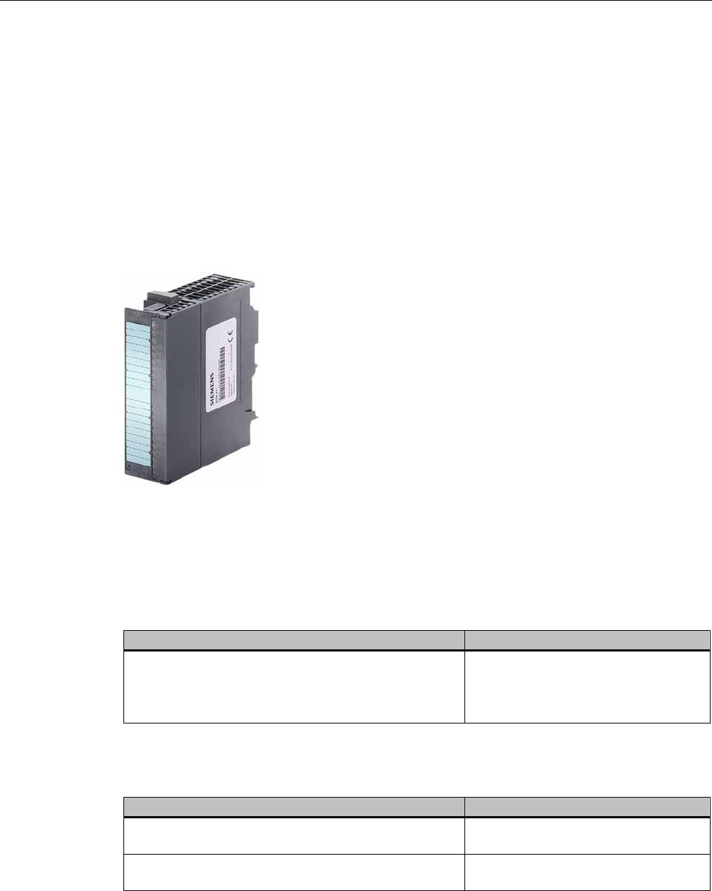
Figure 8-1 Interface module ASM 452
The ASM 452 is the result of consistent development of the familiar ASM 450/451 interface
modules. Optimal data throughput can be achieved even in large-scale PROFIBUS
configurations thanks to the use of acyclic data traffic on PROFIBUS DP V1. The minimum
cyclic data load of the ASM 452 on the PROFIBUS provides the user with the guarantee that
other PROFIBUS nodes (e.g. DI/DO) can still be processed at great speed.
The ASM 452 is an interface module for communication between PROFIBUS and the
RF310R with RS422 interface. Through the ASM 452, the data on the RF300 transponder
can be physically addressed ("Normal" addressing). In SIMATIC S7, FC 45 is available for
this purpose.
8.3.2 Ordering data
Table 8- 2 Ordering data for ASM 452 and accessories
Product description Order No.
ASM 452 interface module for PROFIBUS DP-V1, 1x RF3xxR with
RS422 interface, without connector for 24 V DC and PROFIBUS
6GT2002-0EB20
Accessories:
Connector for PROFIBUS DP and 24 V supply 6ES7194-1AA00-0XA0
Connecting cable RF3xxR ↔ ASM 452

System integration
8.3 ASM 452
SIMATIC RF300
212 System Manual, 11/2009 - Zwischenstand 17.09.2009, A5E01642529-04
Product description Order No.
Plug-in cable, pre-assembled, length: 2 m (standard length) 6GT2891-1CH20
Plug-in cable, pre-assembled, length: 5 m 6GT2891-1CH50
Opt. Cable connector without read/write device cable
(for cable lengths > 20 m) ASM 452 ↔ reader
6GT2090-0BC00
M12 blanking cap for unused RF310R connection (1 pack =
10 pieces)
3RX9802-0AA00
CD "RFID Systems Software & Documentation" with FC 45, GSD
file
6GT2080-2AA10
Replacement part:
Connector plate; T functionality for PROFIBUS connection
6ES7194-1FC00-0XA0
FC 45 Reference Manual
German
English
French
Available in electronic form on
the CD "RFID Systems
Software & Documentation"
The ASM 456 plug-in cables 6GT2891-0Fxxx can be used as extension cables.
System integration
8.3 ASM 452
SIMATIC RF300
System Manual, 11/2009 - Zwischenstand 17.09.2009, A5E01642529-04 213
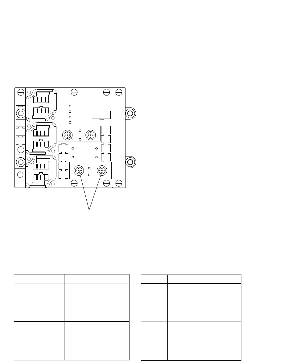
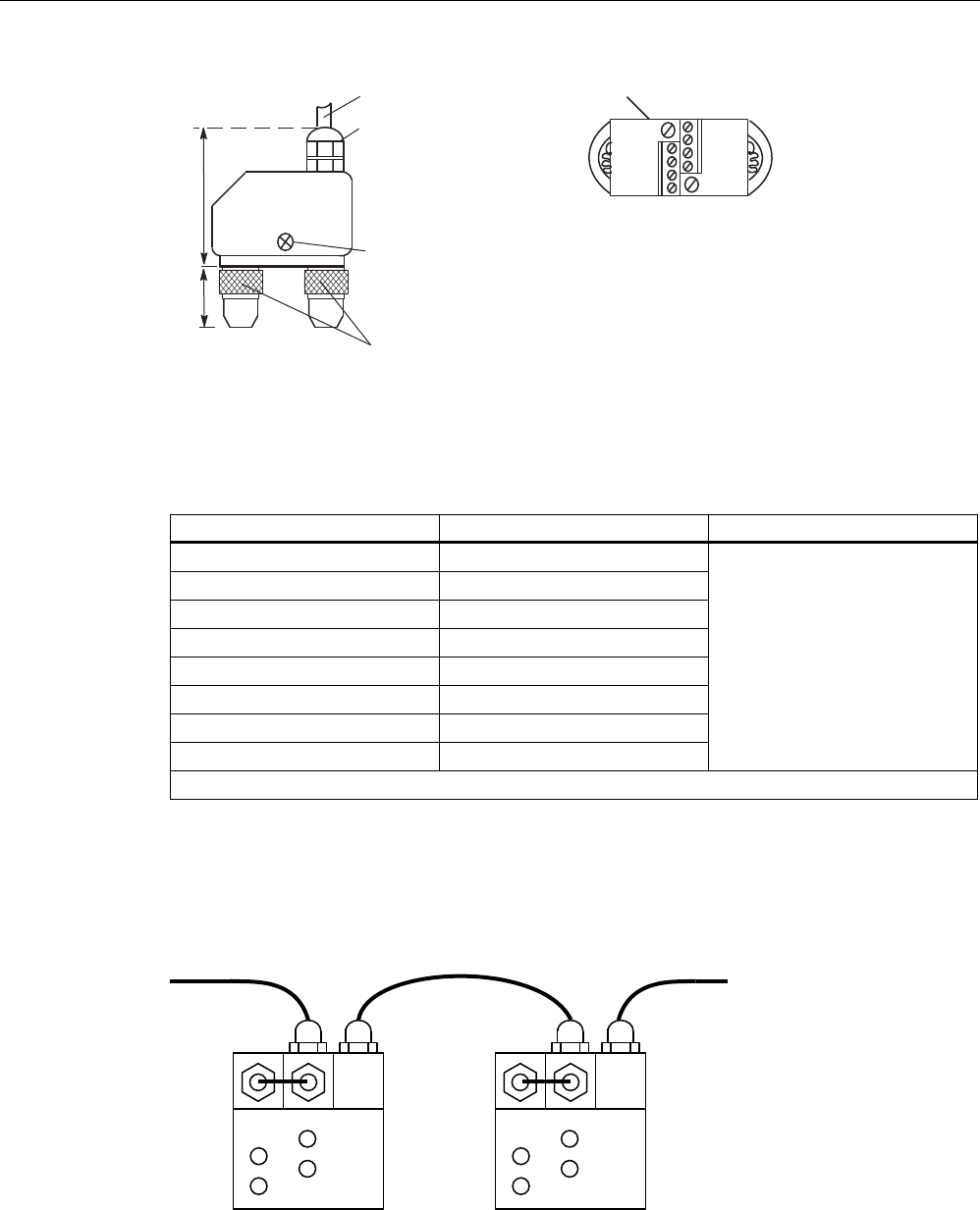
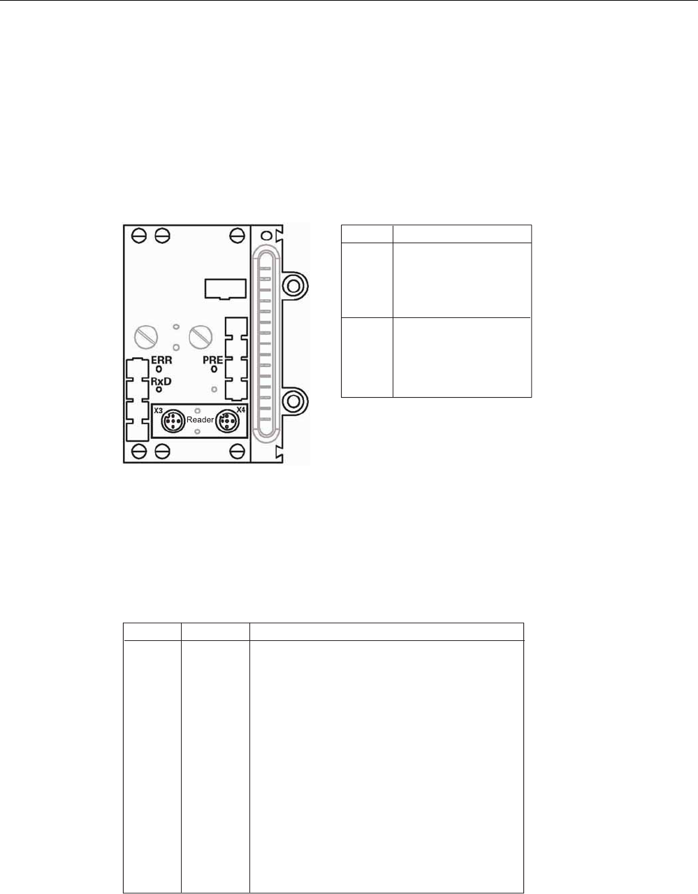
8.3.3 Pin assignment and display elements
Pin assignments
The figure below illustrates the pin assignments of ASM 452.
352),%86'3
6RFNHW
;DQG;
3LQDVVLJQPHQW
6LJQDO % UHG
3(
3(
6LJQDO $ JUHHQ
/
0
6XSSO\
YROWDJH
/('VIRU5)DQG$60
5[' 5HDGHU DFWLYH ZLWK
35((55 7UDQVSRQGHUSUHVHQWRUHUURU
GLVSOD\
35((55 IRUUHDGHU
7KHWUDQVSRQGHUSUHVHQWGLVSOD\DOZD\V
WDNHVSULRULW\7KHHUURULVRQO\LQGLFDWHG
ZKHQDWUDQVSRQGHULVQRW
SUHVHQW
7UDQVSRQGHUSUHVHQW7KH/('LVSHUPDQHQWO\21,IPRUH
WKDQRQHWUDQVSRQGHULVLQWKHILHOGWKH QXPEHURI
WUDQVSRQGHUVLVLQGLFDWHGE\VKRUWLQWHUUXSWLRQV$IDXOWLVQRW
RXWSXW
(UURUGLVSOD\
7KH/('LVSHUPDQHQWO\2))7KHODVWHUURUQXPEHULV
LQGLFDWHGE\EULHIOLJKWSXOVHV
5HDGHU 5HDGHULVVHOHFWHG
5HDGHU 5HDGHULVVHOHFWHG
2QO\UHDGHUFDQEHVHOHFWHG
/('VIRU352),%86'3
6) 6\VWHP )DXOW
%) %XV )DXOW
21 /LJKWV XS ZKHQ WKHUH LV
$60LVJHQHUDWHGE\WKH9VXSSO\YROWDJH
9'& /LJKWVXSZKHQWKH9VXSSO\YROWDJHLV
FRQQHFWHGWRWKH$60
1RWFRQQHFWHG
3LQDVVLJQPHQWUHDGHU6RFNHW
1RWDYDLODEOHIRU5)
;;
;;
$60
; ;
; ;
;
;
;
'&9
5['
35((55
6/*
5['
6/*
35((55
6)
%)
21
3(
/
0
3(
/
0
;
5['
7['
7['
5['
3(
; ;
9 9
'$ '(
9 9
'$ '(
3( 3(
Figure 8-2 Pin assignment and LEDs of ASM 452
System integration
8.3 ASM 452
SIMATIC RF300
214 System Manual, 11/2009 - Zwischenstand 17.09.2009, A5E01642529-04
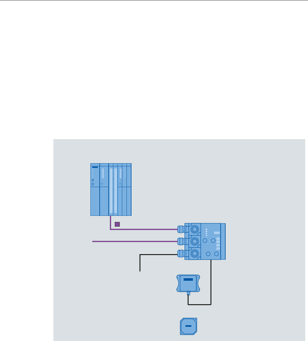
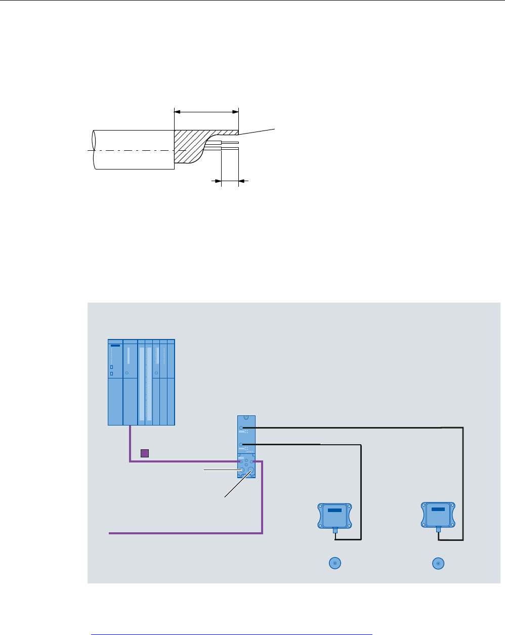
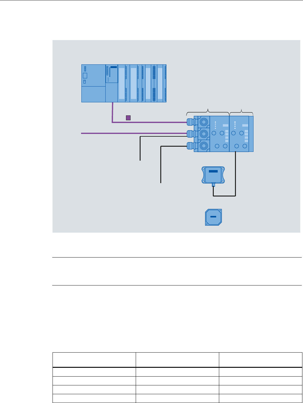
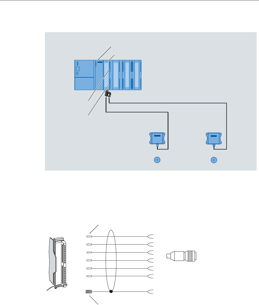
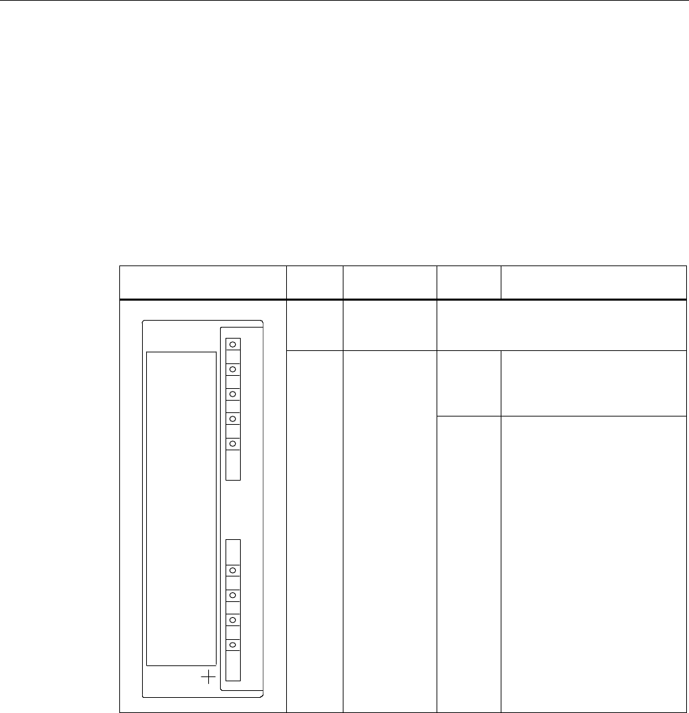
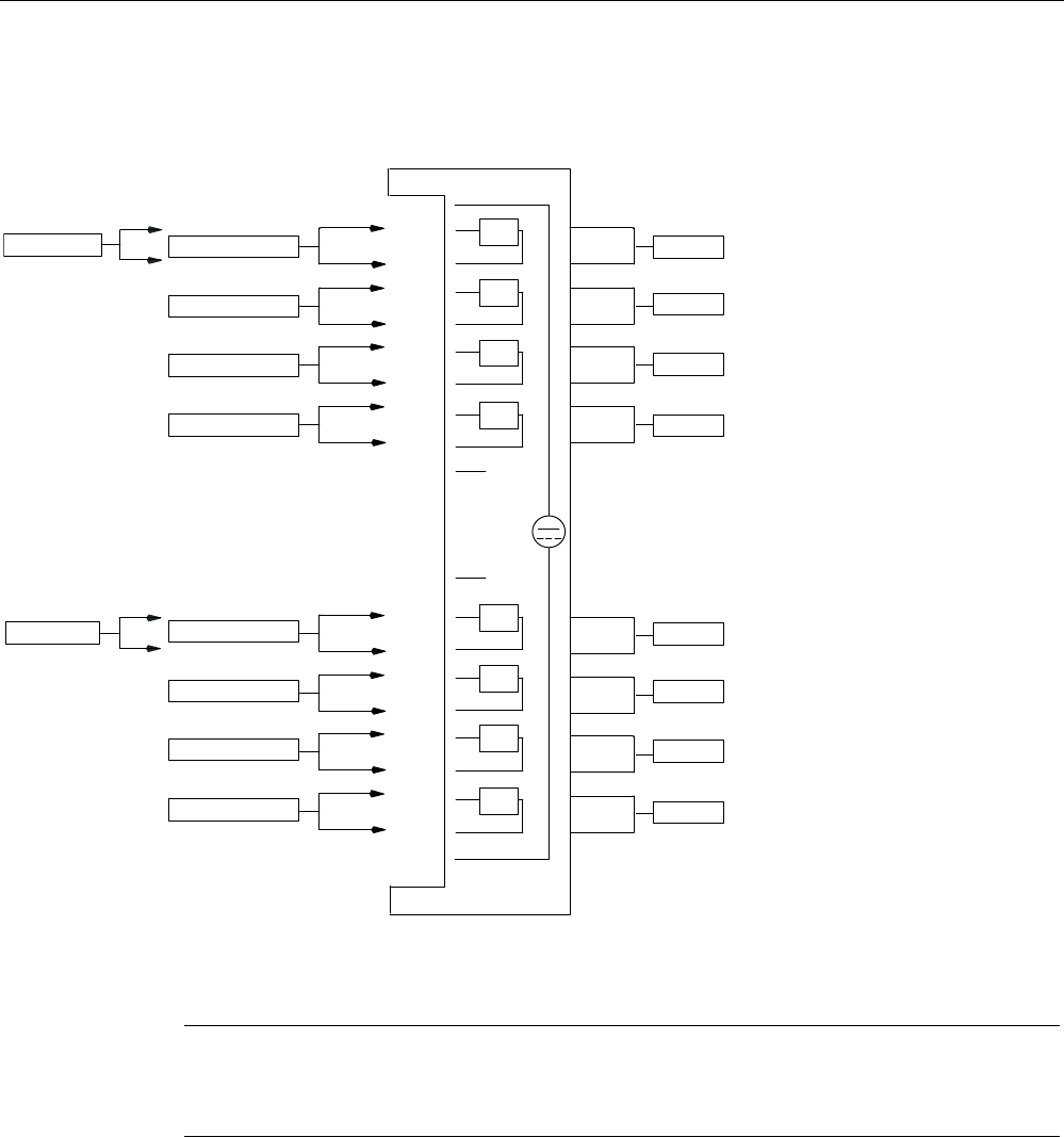
8.3.4 Configuration
Configuration
Hardware description
The ASM 452 has the same housing as the distributed I/O system ET 200X. General
information on ASM 452 (e.g.: assembly, operation and wiring; general technical data) is
available in the ET200X manual (Order No. 6ES7 198-8FA00-8AA0). Descriptions of
accessories and network components can also be found in this manual.
Configuration
352),%86'3
0DVWHUPRGXOH
HJ6&38
9IRU
$60b
WRRWKHU352),%86
EXVQRGHV
352),%86
HJ
5)5
7DJ0'6
$60
Figure 8-3 Configuration of ASM 452
PROFIBUS configuration
The ASM 452 is integrated into the hardware configuration by means of a GSD file. The
ASM can then be configured using the HW Config of SIMATIC Manager or another
PROFIBUS tool.
A GSD file is provided for ASM 452 on the CD "RFID Systems Software & Documentation".
System integration
8.3 ASM 452
SIMATIC RF300
System Manual, 11/2009 - Zwischenstand 17.09.2009, A5E01642529-04 215
Operating mode of the ASM 452
The approved operating modes of ASM 452 are described in the GSD file. It is set using the
hardware configuration tool (e.g. STEP 7 HW Config).
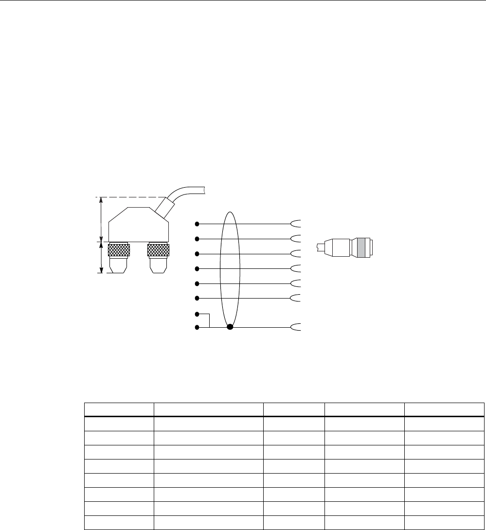
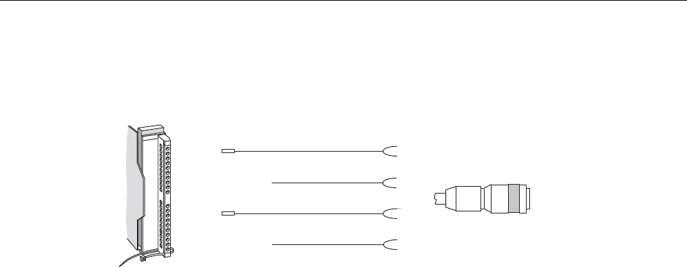
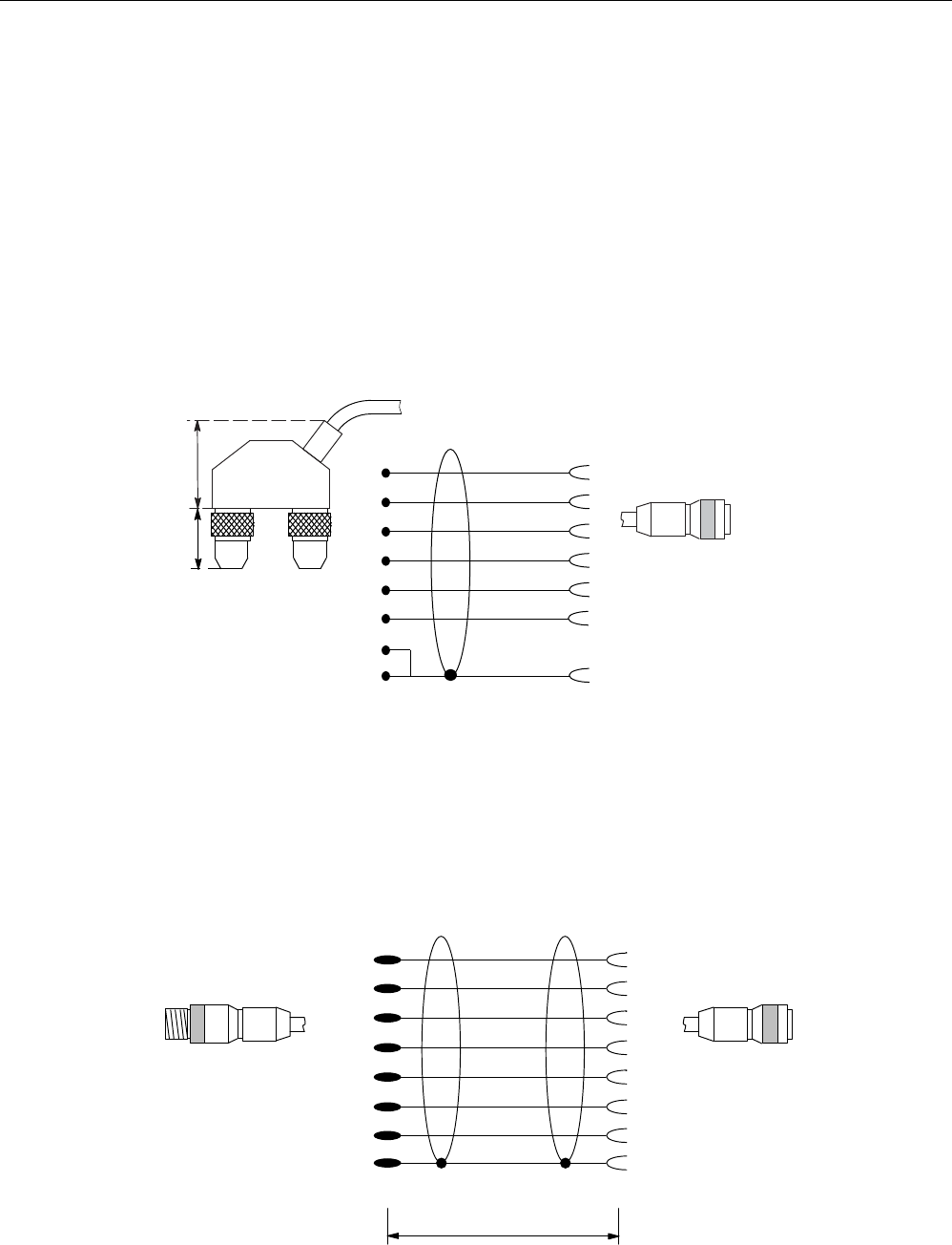
Reader connection system
A reader always occupies two M12 connector sockets on the ASM 452.
A pre-assembled cable therefore ensures easy connection of the reader (see figure below).
The connecting cable is available in lengths of 2 m (standard) and 5 m. Extensions are
possible up to 1000 m using connecting cables 6GT2891-… .
JUD\
JUHHQ
ZKLWH
EURZQ
\HOORZ
SLQN
VKLHOG
7ZRSLQ0
FLUFXODUFRQQHFWRUV
$60VLGH 5HDGHUVLGH
0SLQ
;
;
;
;
;
;
;
; ;
;
Figure 8-4 Connecting cable (2 m) ASM 452/473 ↔ RF3xxR reader with RS422 (6GT2891-1CH20)
Cable installation
Signal M12 (reader side) Cable X1 / Data X2
24 V DC 1 Pink - 1
TX - 2 Yellow 4 -
GND 3 Gray - 3
TX + 4 Green 1 -
RX + 5 white 2 -
RX - 6 brown 3 -
- - -
Shield 8 + terminal piece Shield 5 5
Cable assignment ASM 452/473 ↔ RF3xxR reader with RS422 (6GT2891-1CH20)
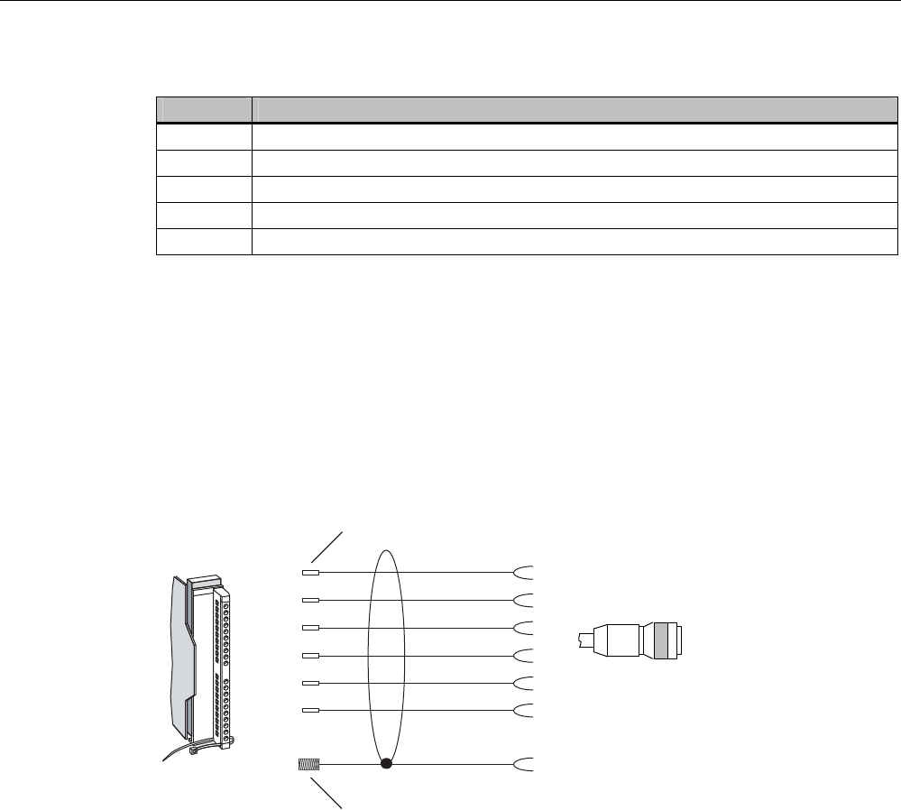
A reader cable connector with screw-type terminals is provided for users who want to
individually pre-assemble their own cables (see figure below). Cables and reader cable
connectors can be ordered from the MOBY catalog.
System integration
8.3 ASM 452
SIMATIC RF300
216 System Manual, 11/2009 - Zwischenstand 17.09.2009, A5E01642529-04
6
6
VFUHZV
IRURSHQLQJ
WKHFRQQHFWRU
&RQQHFWRU
0WR$60
'HJUHHRISURWHFWLRQ,3
3*FDEOHJODQG
PD[FDEOHGLDPHWHU
PPRQO\VFUHZGRZQ
DIWHUDVVHPEOLQJWKH
FRQQHFWRU
$60FDEOH*7 &RQQHFWRUFRYHUUHPRYHG
Figure 8-5 Cable connector ASM 452/473 ↔ RF3xx reader with RS422 (6GT2090-0BC00)
Pin assignment for ASM 452/473 cable connector
Connector pin Connection to pin of the reader Wire color
1 4
2 5
3 6
4 2
5 3
6 1
-
S 8 + terminal piece
Note data sheet provided by the
manufacturer
Pin 7 must not be connected.
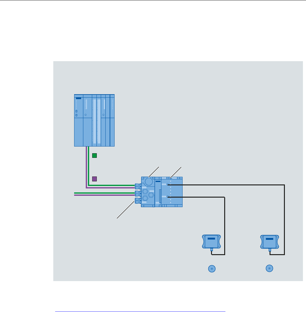
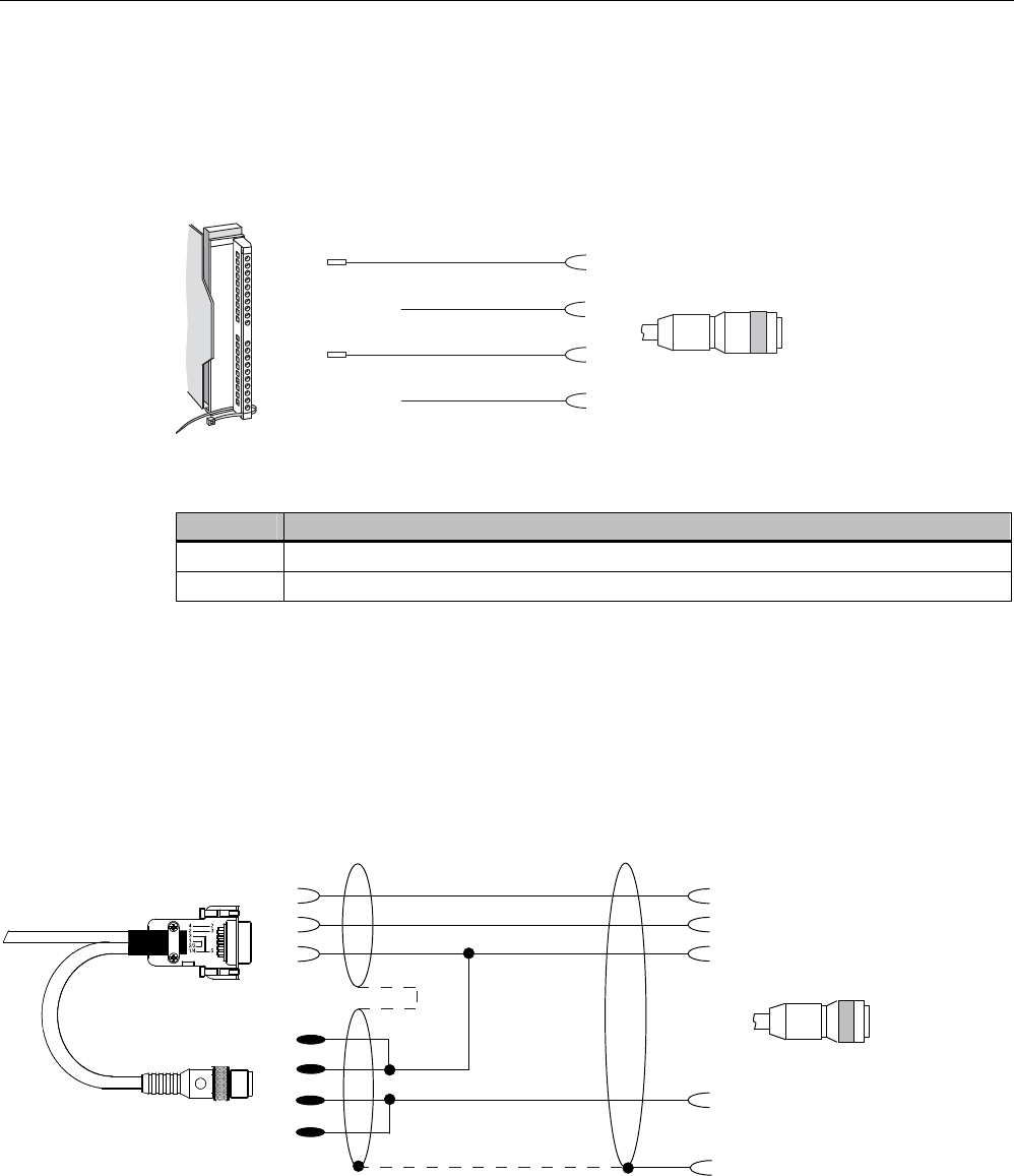
PROFIBUS cable with 24 V supply
The ASM 452 can also be operated with the "green" PROFIBUS cable. It is important to
ensure that a 24 V cable is connected from X12 to X13. The 24 V cable can be connected to
pins 5 and 6 in plug X12.
; ;
;
; ;
;
Figure 8-6 PROFIBUS cable with 24 V supply
System integration
8.3 ASM 452
SIMATIC RF300
System Manual, 11/2009 - Zwischenstand 17.09.2009, A5E01642529-04 217
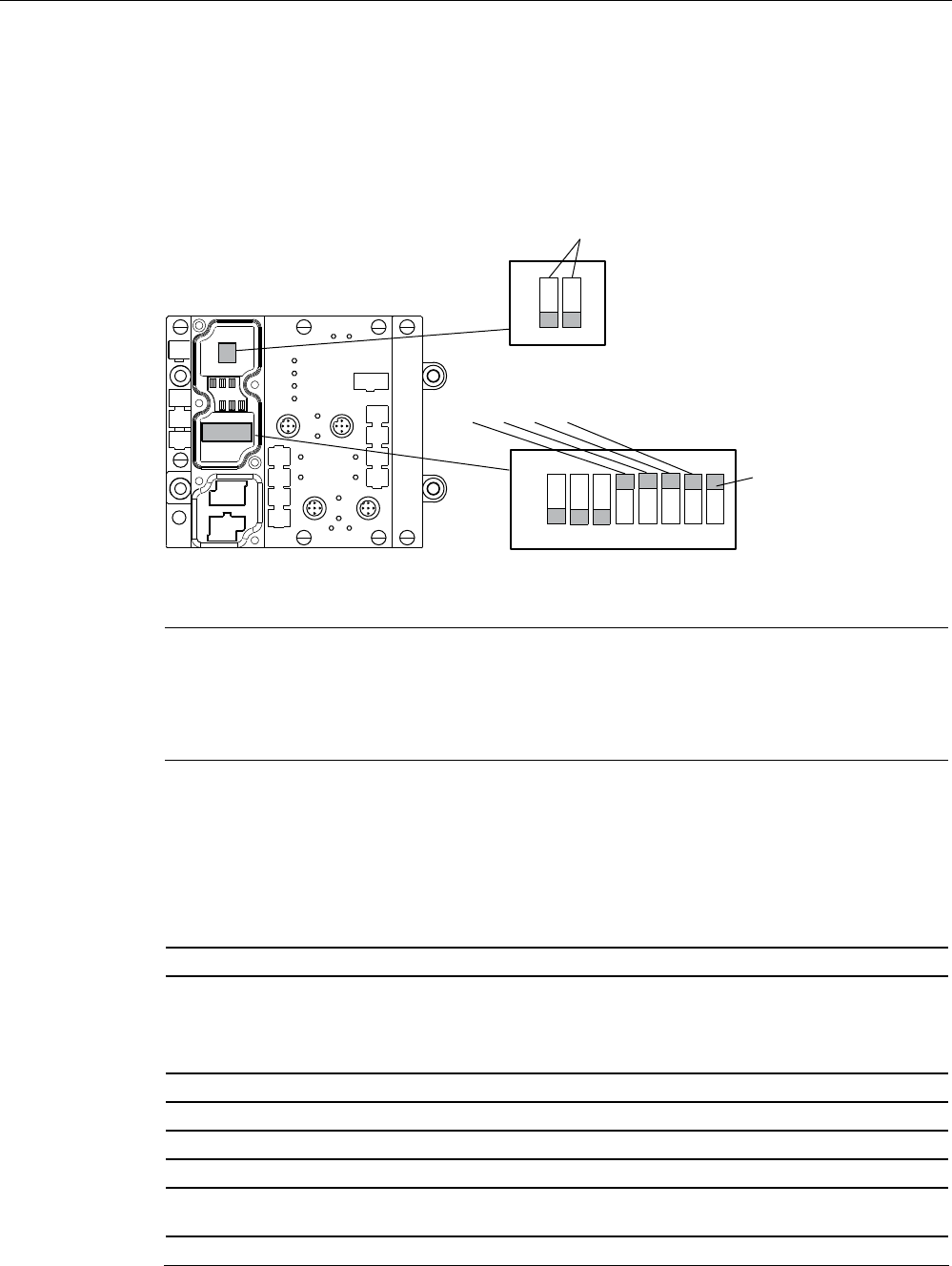
PROFIBUS address and terminating resistor
You must remove the connector plate from the ASM before you set the
PROFIBUS address or connect the terminating resistor. The connector plate covers the DIL
switch. The position of the DIL switch in ASM is shown in the figure below with one setting
example for each case.
21
2II
RQ
([DPSOH352),%86DGGUHVVRQGHOLYHU\
([DPSOH7HUPLQDWLQJUHVLVWRU2II
$VGHOLYHUHGVWDWH
6WDQGDUG
PRGH
XVH*6'ILOH
6,(0%
Figure 8-7 Setting the PROFIBUS address/connecting the terminating resistor
Note
The PROFIBUS address in ASM 452 must always match the PROFIBUS address defined
in the configuring software for this ASM.
To ensure that the terminating resistor functions correctly, you must always switch both
DIL switches of the terminating resistor to "on" or "off".
8.3.5 Technical data
Table 8- 3 Technical data for ASM 452
Serial interface to the user PROFIBUS DP-V1
Procedure after connection EN 50170 Vol. 2 PROFIBUS
PG 11 cable gland
PROFIBUS and power supply connectors are not included
in the scope of delivery
Transmission rate 9600 baud to 12 Mbaud (automatic detection)
Max. block length 2 words cyclic/240 bytes acyclic
Serial interface to the RF3xxR
Connector 2 x M12 coupler plug
Max. cable length 2 m = Standard length, 5 m, 10 m, 20 m and 50 m,
(up to 1000 m on request)
Readers that can be connected 1x RF3xxR with RS422 interface

System integration
8.3 ASM 452
SIMATIC RF300
218 System Manual, 11/2009 - Zwischenstand 17.09.2009, A5E01642529-04
Software functions
Programming Depending on the PROFIBUS DP master
Function blocks for SIMATIC S7 FC 45
Transponder addressing Direct access via addresses
Commands Initialize transponder, read data from transponder, write
data to transponder
Multi-tag capability No
S7 data structures via UDTs Yes
Power supply
Rated value 24 V DC
Permissible range 20 V to 30 V DC
Current consumption Max. 180 mA; typ. 130 mA (without reader)
Digital inputs none
Digital outputs none
Ambient temperature
Operation 0 °C to +55 °C
Storage and transport -40 °C to +70 °C
Dimensions (W x H x D) in mm 134 x 110 x 55 (without bus connector)
Fixing 4 M5 screws;
for mounting on any plate or wall
Weight, approx. 0,5 kg
Degree of protection IP67
MTBF (at 40 °C) 30 • 104 hours = 34 years
8.3.6 PROFIBUS Diagnosis
The following table lists possible error indications with their meanings and provides
remedies.
Table 8- 4 LED indication for PROFIBUS diagnosis
"BF" LED "SF"LED Cause of error Error correction
ASM 452 is in start-up mode. -
The connection to the DP master
has failed.
ASM 452 not detecting a baud
rate.
Check the PROFIBUS DP
connection.
Check the DP master.
ON *
Bus interrupt
DP Master not functioning
Check all cables on your
PROFIBUS DP network.
Check whether the connector
plugs for PROFIBUS DP are
securely plugged into the
ASM 452.
System integration
8.3 ASM 452
SIMATIC RF300
System Manual, 11/2009 - Zwischenstand 17.09.2009, A5E01642529-04 219
"BF" LED "SF"LED Cause of error Error correction
flashes on The configuration data sent to
the ASM 452 by the DP master
do not match the configuration of
the ASM 452.
Check the configuration of
the ASM 452 (input/output,
PROFIBUS address).
Correct GSD file being used?
– SIEM80B6.GSD for
ASM 452
Flashes Off ASM 452 has detected the baud
rate, but is not being addressed
by the DP Master.
ASM 452 has not been
configured.
Check the PROFIBUS
address set on the ASM 452
or in the configuration
software.
Check the configuration of
the ASM 452 (station type).
on Flashes There is a hardware defect in the
ASM 452.
Replace the ASM 452.
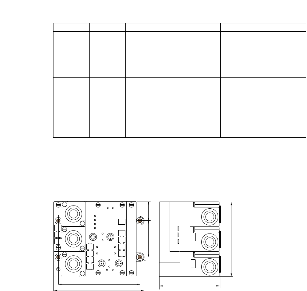
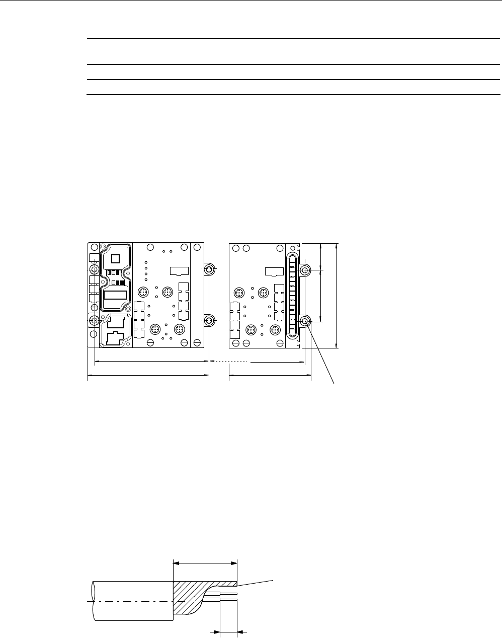
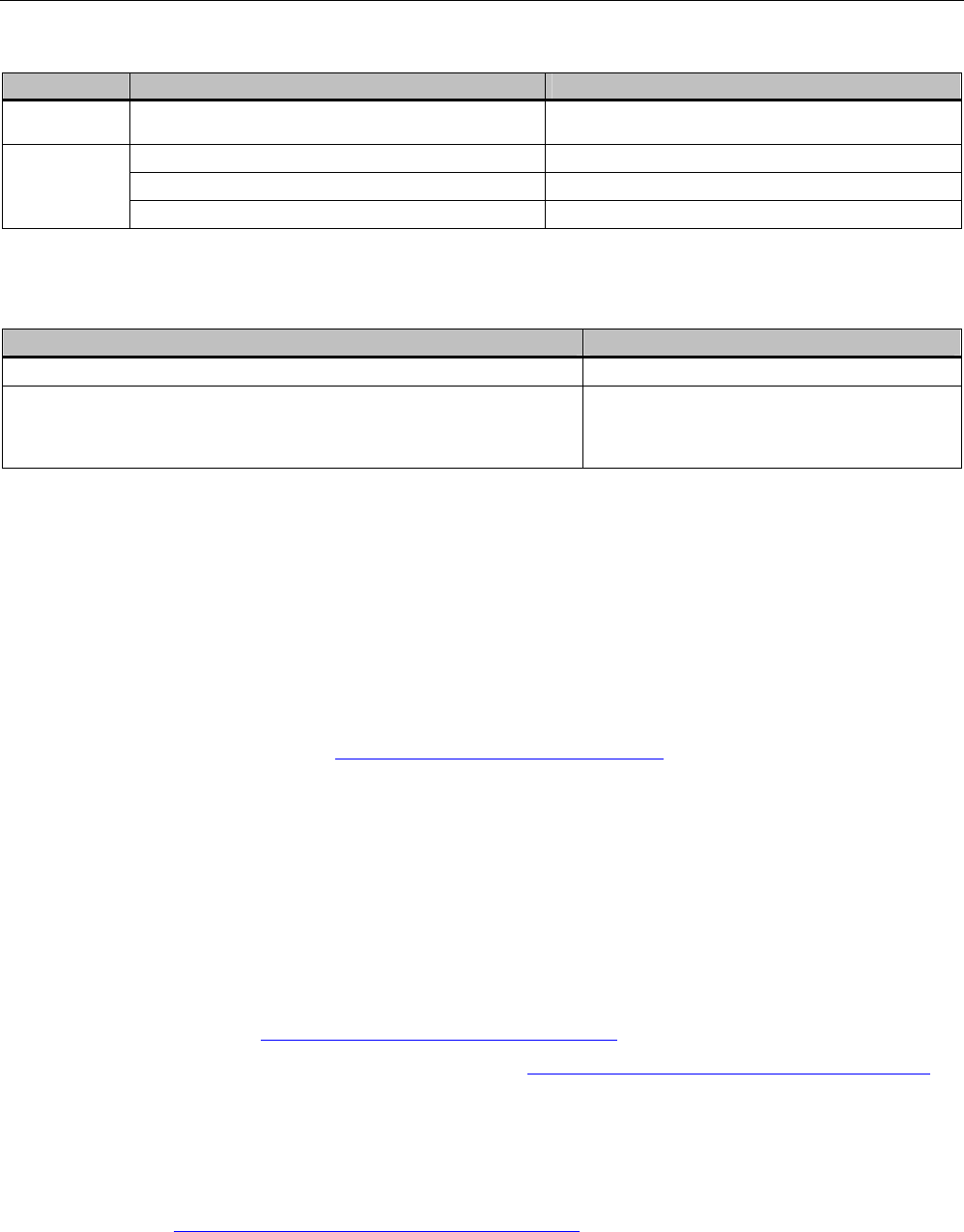
8.3.7 Dimension drawing
The following figure shows the dimensional drawing of an ASM 452 with bus connectors.
You must add the length of the PG cable gland and the radius of the cable used to the
measured overall width and depth.
Figure 8-8 Dimensional drawing of ASM 452
System integration
8.4 ASM 456
SIMATIC RF300
220 System Manual, 11/2009 - Zwischenstand 17.09.2009, A5E01642529-04
Example of stripped lengths
The following diagram shows an example of stripped lengths. The lengths apply to all cables
which can be connected to the connector plugs. You must twist any shield braid present,
plug into a core end sleeve and cut off any excess.
7ZLVWHGDQG
WUXQFDWHG
VKLHOGEUDLGLQJ
Figure 8-9 Length of stripped insulation for PROFIBUS cables
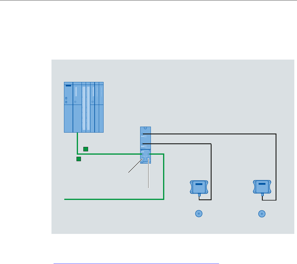
8.4 ASM 456
Configured with ASM 456
352),%86'3
0DVWHUPRGXOH
6,0$7,&b6
9IRU
$60DQGUHDGHU
WRRWKHU352),%86
EXVQRGHV
HJ
5)5
HJ
5)5
352),%86
$60b
7DJV0'6
7DJV0'6
9WRRWKHU352),%86
EXVQRGHV
Figure 8-10 Configuration of ASM 456
For more detailed information, please refer to ASM 456 Operating Instructions
(http://support.automation.siemens.com/WW/view/en/32629442).
System integration
8.5 ASM 473
SIMATIC RF300
System Manual, 11/2009 - Zwischenstand 17.09.2009, A5E01642529-04 221
8.5 ASM 473
8.5.1 Features
Field of application
The ASM 473 interface module is an RF300 module for SIMATIC S7. It can be plugged into
the ET 200X distributed I/O station and DESINA. ET 200X is operated by the user over
PROFIBUS DP V1. An S7-300 or S7-400 with integrated PROFIBUS connection can be
used as the controller.
ASM 473 supplements the SIMATIC S7 interface module ASM 475. The IP67 degree of
protection means that it can be installed and operated in the process without the need for an
additional protective housing.
To operate the ASM 473, an ET 200X basic module BM 141/142 with the order number
6ES7141-1BF11-0XB0 or 6ES7142-1BD21-0XB0 or a BM 143 is required.
The transponder data are accessed by means of physical addressing of the transponder.
For operation in a SIMATIC S7, the function FC 45 is available. The hardware of the ASM
473 is configured with an object manager (OM) that is integrated in the SIMATIC Manager.
Figure 8-11 Interface module ASM 473
Other features:
● Up to 7 ASM 473 interface modules can be operated simultaneously in an ET 200X
station.
● Any other I/O modules from the ET 200X spectrum can be operated with the ASM 473.
8.5.2 Ordering data
Table 8- 5 Ordering data for ASM 473 and accessories
Product description Order No.
Interface module ASM 473
1x RF3xxR reader with RS422 interface
6GT2002-0HA10
Accessories:

System integration
8.5 ASM 473
SIMATIC RF300
222 System Manual, 11/2009 - Zwischenstand 17.09.2009, A5E01642529-04
Product description Order No.
Connecting cable ASM 473 ↔ Reader RF3xxR
Plug-in cable, pre-assembled, length 2 m (standard length) 6GT2891-1CH20
Plug-in cable, pre-assembled, length 5 m 6GT2891-1CH50
Opt. Cable connector without reader cable
(for cable lengths > 20 m) ASM 473 ↔ Reader
6GT2090-0BC00
CD "RFID Systems Software & Documentation" with FC 45,
GSD file
6GT2080-2AA10
FC 45 Reference Manual
German
English
French
Available in electronic form on the
CD "RFID Systems Software &
Documentation"
System integration
8.5 ASM 473
SIMATIC RF300
System Manual, 11/2009 - Zwischenstand 17.09.2009, A5E01642529-04 223
8.5.3 Pin assignment and display elements
Pin assignments
The figure below illustrates the pin assignment for the read/write device and the display
elements.
2))
+]
+]
2))21
+]
+]
+]
2))
;
;
21SHUP
2))21
5['
7['
7['
5['
3(
9
QF
9
QF
3(
(5535(
[IODVK
HYHU\V
6RFNHW 3LQDVVLJQPHQWUHDGHU
/('VIRU352),%86'3
*HQHUDOLQGLFDWRUV6)%)219'&DUHORFDWHGRQWKHEDVLFPRGXOH
RIWKH(7;
/('VIRU02%<
5[' 5HDGHUDFWLYHZLWKFRPPDQG
35( ,QGLFDWHVWKHSUHVHQFHRIDWUDQVSRQGHU
(55 (UURULQGLFDWHGE\IODVKLQJVHTXHQFH
7KHIROORZLQJ$60VWDWHVDUHDOVRLQGLFDWHGZLWKWKH/('V35(DQG
(55
'HVFULSWLRQ&DXVHV5HPHG\
+DUGZDUHLVGHIHFWLYH5$0IODVK
&KDUJHULVGHIHFWLYHFDQRQO\EHUHSDLUHGLQWKH
IDFWRU\
)LUPZDUHORDGLQJLVDFWLYHRUQR
ILUPZDUHGHWHFWHG
ൺ/RDGILUPZDUH
ൺ$60PXVWQRWEHVZLWFKHGRIIXQWLOORDGHG
)LUPZDUHORDGLQJWHUPLQDWHGZLWKHUURUV
ൺ5HVWDUWUHTXLUHG
ൺ/RDGILUPZDUHDJDLQ
ൺ&KHFNXSGDWHILOHV
2SHUDWLQJV\VWHPHUURU
ൺ6ZLWFK$60RU(7;EDVHVWDWLRQ2))21
$60KDVERRWHGDQGLVZDLWLQJIRUD5(6(7
LQLWBUXQIURPWKHXVHU
Figure 8-12 Interfaces and indicators of the ASM 473 for RF300
System integration
8.5 ASM 473
SIMATIC RF300
224 System Manual, 11/2009 - Zwischenstand 17.09.2009, A5E01642529-04
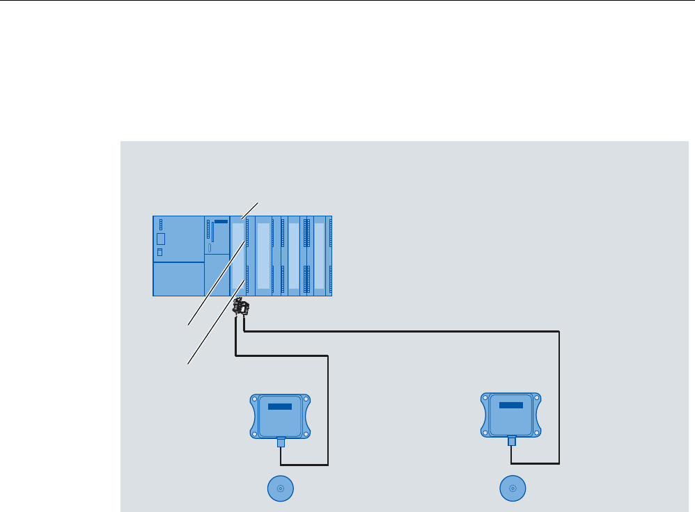
8.5.4 Configuration
9VXSSO\
)RUUHDGHU
9VXSSO\
IRU(7;
(OHFWURQLFV
%DVLFPRGXOH
(7;%0
(7;%0
(7;%0
'(6,1$%0 $60b
WRRWKHU352),%86
EXVQRGHV
352),%86'3
0DVWHUPRGXOH
6,0$7,&b6
HJ
5)5
0'67DJ
352),%86
Figure 8-13 Configuration of ASM 473
Note
It differs from ASM 452 in that for ET 200X the 24 V supply must be connected to the
PROFIBUS connector and on the load voltage connector (see the ET 200X manual).
Basic module - Requirements for operation of ASM 473
The following table indicates the status of the ET 200X basic module of 10/2002. The
functionality of new basic modules is stored in HW Config of the SIMATIC Manager.
Table 8- 6 Requirements for operation of ASM 473
Order number of the ET 200X
basic module
For operation with ASM 473
(6GT2002-0HA00)*
For operation with ASM 473
PARAM (6GT2002-0HA10)
6ES7141-1BF00-0XB0 No No
6ES7141-1BF00-0AB0 Yes Yes
6ES7141-1BF01-0XB0 No No
6ES7141-1BF10-0XB0 No No

System integration
8.5 ASM 473
SIMATIC RF300
System Manual, 11/2009 - Zwischenstand 17.09.2009, A5E01642529-04 225
Order number of the ET 200X
basic module
For operation with ASM 473
(6GT2002-0HA00)*
For operation with ASM 473
PARAM (6GT2002-0HA10)
6ES7141-1BF11-0XB0 Yes Yes
6ES7141-1BF40-0AB0 Yes Yes
6ES7142-1BD10-0XB0 No No
6ES7142-1BD11-0XB0 No No
6ES7142-1BD20-0XB0 No No
6ES7142-1BD21-0XB0 Yes Yes
6ES7142-1BD22-0XB0 No Yes**
6ES7143-1BF00-0AB0 Yes Yes
6ES7143-1BF00-0XB0 Yes Yes
6ES7147-1AA00-0XB0 No No
6ES7147-1AA01-0XB0 No Yes
* Discontinued
** Notes on operation:
In HW Config, please parameterize the module 6ES7142-1BD21-0XB0.
System integration
8.5 ASM 473
SIMATIC RF300
226 System Manual, 11/2009 - Zwischenstand 17.09.2009, A5E01642529-04
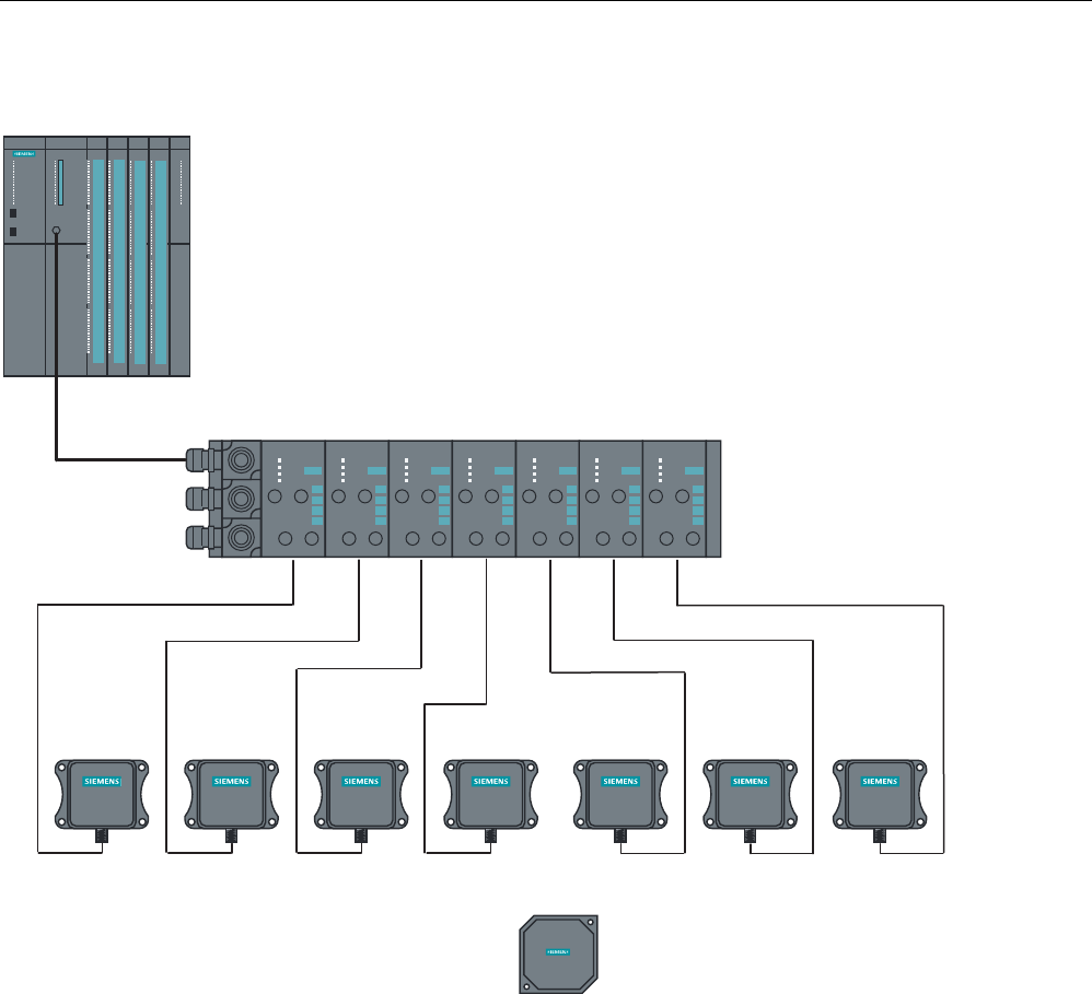
Example for a maximum configuration of ASM 473 on an ET 200X
5)[[7
5)[[5
6,0$7,&
5)5
6,0$7,&
5)5
6,0$7,&
5)5
6,0$7,&
5)5
6,0$7,&
5)5
6,0$7,&
5)5
6,0$7,&
5)5
6,0$7,&
5)7
0D[$60FDQEHRSHUDWHGLQDQ(7;
Figure 8-14 Example for a maximum configuration of ASM 473 on an ET 200X
Depending on the PROFIBUS master, up to 123 ET 200X modules can be run on one
PROFIBUS branch.
Hardware configuration
The ASM 473 is integrated in the hardware configuration of the SIMATIC Manager by calling
Setup.exe in the directory daten\S7_OM on the "RFID Systems Software & Documentation"
CD. Currently, the ASM 473 cannot be integrated in masters of other manufacturers.
Reader connection system
A reader always occupies the two M12 connection sockets X3 and X4 on the ASM 473. A
prefabricated cable makes it easy to connect the reader. The standard version of the
connecting cable is 2 m in length. Other cable lengths are available on request.
For customers who want to assemble their own cables, an ASM cable connector with screw-

System integration
8.5 ASM 473
SIMATIC RF300
System Manual, 11/2009 - Zwischenstand 17.09.2009, A5E01642529-04 227
type terminals is available. Cables and ASM cable connectors can be ordered from the
MOBY catalog.
8.5.5 Technical data
Table 8- 7 Technical specifications for ASM 473
Interface for ET 200X SIMATIC S7 I/O bus
cyclic/acyclic services
Communication 2 words cyclic/238 bytes acyclic
Command buffer in ASM 142 x 238 bytes
Serial interface to the reader
Connector 2 x M12 coupler plug
Max. cable length 2 m = standard length; other pre-assembled
cables = 5 m, (up to 1000 m on request)
Readers that can be connected 1 x RF3xxR reader with RS422
Software functions
Programming Depending on the PROFIBUS DP master
Function blocks for SIMATIC S7 FC 45, FB 45, FC 55
MDS addressing Direct access via addresses
Commands Initialize transponder, read data from
transponder, write data to transponder, etc.
PROFIBUS Diagnosis Yes; in accordance with ET 200X basic station
S7 diagnostics Yes, can be called up via S7 OM
Reloadable firmware Yes, via S7 OEM
Power supply 1
Rated value 24 V DC
Permissible range 20.4 V to 28.8 V DC
Current consumption Typ. 75 mA; max. 500 mA
(or see Technical specifications of the connected
reader)
Power dissipation of the module Typically 1.6 W
Digital outputs/inputs Via expansion modules from the ET 200X
spectrum
Ambient temperature
Operation 0 °C to +55 °C
Transport and storage -40 °C to +70 °C
Dimensions (W x H x D) in mm
Single unit 87 x 110 x 55
Width module 60 x 110 x 55
System integration
8.5 ASM 473
SIMATIC RF300
228 System Manual, 11/2009 - Zwischenstand 17.09.2009, A5E01642529-04
Fixing 2 M5 screws (customer side)
2 M3 screws (product side)
Degree of protection IP67
Weight, approx. 0.275 kg
For installation instructions and general technical data, see the ET 200X manual.
8.5.6 Dimensional drawings
Dimension drawing for mounting holes
The figure below shows the dimensions for the position of the holes for the fixing screws for
a basic module and an ASM 473 expansion module.
%0 $60b
Q[
Q 1XPEHURIH[SDQVLRQPRGXOHV
)RU0IL[LQJ
VFUHZ
Figure 8-15 Dimensions for fixing holes for basic modules and expansion modules
Example of stripped lengths
The following diagram shows an example of stripped lengths. The lengths apply to all cables
which can be connected to the connector plugs. You must twist any shield braid present,
plug into a core end sleeve and cut off any excess.
7ZLVWHGDQG
WUXQFDWHG
VKLHOGEUDLGLQJ
Figure 8-16 Length of stripped insulation for PROFIBUS cables
System integration
8.6 ASM 475
SIMATIC RF300
System Manual, 11/2009 - Zwischenstand 17.09.2009, A5E01642529-04 229
8.6 ASM 475
8.6.1 Features
Area of application
The ASM 475 interface module acting as the link between all RF300 systems and SIMATIC
S7-300 performs the functions of a communication module. It can be operated centrally in
the S7-300 or decentrally in an ET200M.
As many as eight ASM 475 interface modules can be plugged into one SIMATIC S7-300
rack and operated. In a configuration with several racks (max. four), the ASM 475 can be
plugged into and operated on any rack. This means that as many as 32 ASMs can be
operated in the maximum configuration of a SIMATIC S7-300. The ASM can also be
operated in the ET 200M distributed I/O on PROFIBUS. Operation in an S7-400 environment
is therefore problem-free. Up to 8 ASMs can be operated on each ET200M.
Error messages and operating states are indicated by LEDs.
A configuration that is resistant to interference is possible due to electrical isolation between
the read/write device and the SIMATIC S7-300 bus.
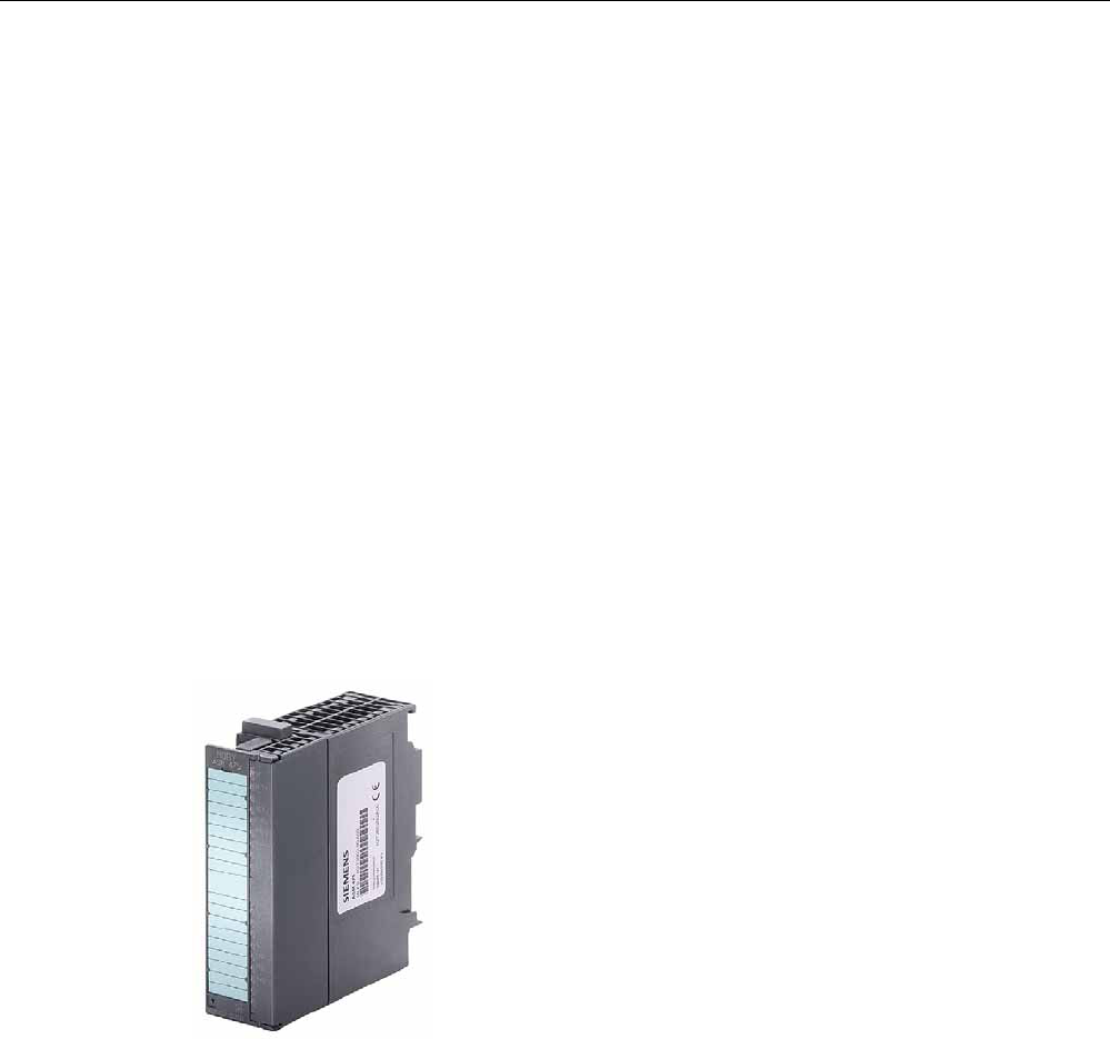
Figure 8-17 Interface module ASM 475
The ASM 475 with the order number 6GT2002-0GA10 is a parameterizable module. The
basic functions of the module are then already specified when the module is configured in
HW Config (e.g. standard addressing).
The data in the MDS is accessed direct by means of physical addresses using the ASM 475.
Operation in a SIMATIC S7 is controlled by the function FC 45.
ASM 475 and FC 45 form a unit that is used for reading the data of the MDS easily and at
optimal speed.

System integration
8.6 ASM 475
SIMATIC RF300
230 System Manual, 11/2009 - Zwischenstand 17.09.2009, A5E01642529-04
8.6.2 Ordering data
Table 8- 8 Ordering data for ASM 475 and accessories
Product description Order No.
ASM 475 interface module for SIMATIC S7
2 x RF3xxR reader with RS422 can be connected in parallel,
without front connector
6GT2002-0GA10
Accessories:
Front connector (1 x per ASM) 6ES7392-1AJ00-0AA0
Connecting cable ASM 475 ↔ RF3xxR
Plug-in cable, pre-assembled, length: 2 m (standard length) 6GT2891-0EH20
Plug-in cable, pre-assembled, length: 5 m 6GT2891-0EH50
Terminal element (1 x per reader cable) 6ES7390-5BA00-0AA0
Shield connecting element 6ES7390-5AA00-0AA0
CD "RFID Systems Software & Documentation" with FC 45,
S7 object manager
6GT2080-2AA10
FC 45 Reference Manual
German
English
French
Available in electronic form on the
CD "RFID Systems Software &
Documentation"
The ASM 456 plug-in cables 6GT2891-0Fxxx can be used as extension cables.
System integration
8.6 ASM 475
SIMATIC RF300
System Manual, 11/2009 - Zwischenstand 17.09.2009, A5E01642529-04 231
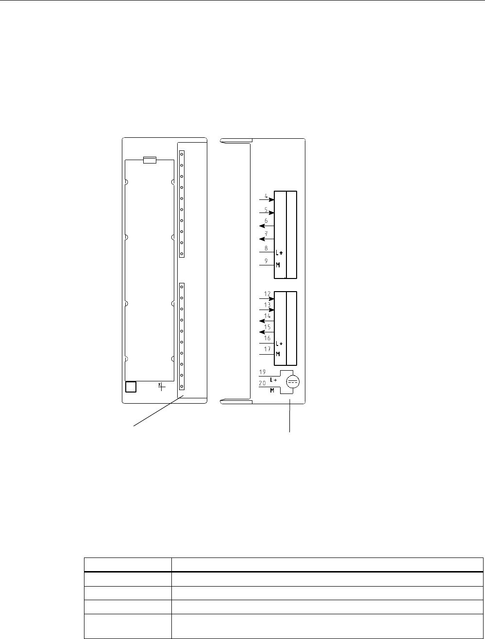
8.6.3 Indicators
Bezel and indicator elements
The figure below illustrates the bezel of the ASM 475 and the inside of the front door
complete with the associated connection diagram. The read/write devices must be
connected to the ASM in accordance with the connection diagram.
6WDWXVDQGHUURUGLVSOD\V &RQQHFWLRQGLDJUDP
7KHQXPEHUVRIWKH
FRQQHFWLRQVUHIHUWR
&RQQHFWRU;RIWKH
WRSHQFORVXUHVHFWLRQ
$60
02%<
6/*b
6
6
(
(
6
6
(
(
6)
9'&
$&7B
(55B
35(B
5['B
$&7B
(55B
35(B
5['B
6/*b
*7b*$
Figure 8-18 Bezel and inside of the front door of the ASM 475
Display elements on the ASM
Table 8- 9 Function of the LEDs on the ASM 475
Light emitting diode Meaning
SF System fault (hardware error on ASM)
DC 5V 24 V are connected to ASM and the 5 V voltage on ASM is OK.
ACT_1, ACT_2 The corresponding reader is active in processing a user command.
ERR_1, ERR_2 A flashing pattern indicates the last error to occur. This display can be reset
using the parameter Option 1.

System integration
8.6 ASM 475
SIMATIC RF300
232 System Manual, 11/2009 - Zwischenstand 17.09.2009, A5E01642529-04
Light emitting diode Meaning
PRE_1, PRE_2 Indicates the presence of a transponder.
RxD_1, RxD_2 Indicates live communication with the reader. In the event of a fault on the
reader, this display may also be lit.
On the ASM 475, further operating states are indicated with the LEDs PRE, ERR and SF:
Table 8- 10 Operating status display on ASM 475 via LEDs
SF PRE_1 ERR_1 PRE_2 ERR_2 Meaning
ON OFF/ON ON
(perm.)
OFF/ON ON
(perm.)
Hardware is defective (RAM, Flash, etc.)
ON OFF ON OFF OFF Charger is defective (can only be repaired in
the factory).
OFF 2 Hz OFF 2 Hz OFF Firmware loading is active or no firmware
detected
Firmware download
ASM must not be switched off
OFF 2 Hz 2 Hz 2 Hz 2 Hz Firmware loading
terminated with errors
Restart required
Load firmware again
Check update files
Any
value
5 Hz 5 Hz 5 Hz 5 Hz Operating system error
Switch ASM off/on
OFF OFF 1 flash
every 2 s
OFF 1 flash
every 2 s
ASM has booted and is waiting for a RESET
(init_run) from the user.
System integration
8.6 ASM 475
SIMATIC RF300
System Manual, 11/2009 - Zwischenstand 17.09.2009, A5E01642529-04 233
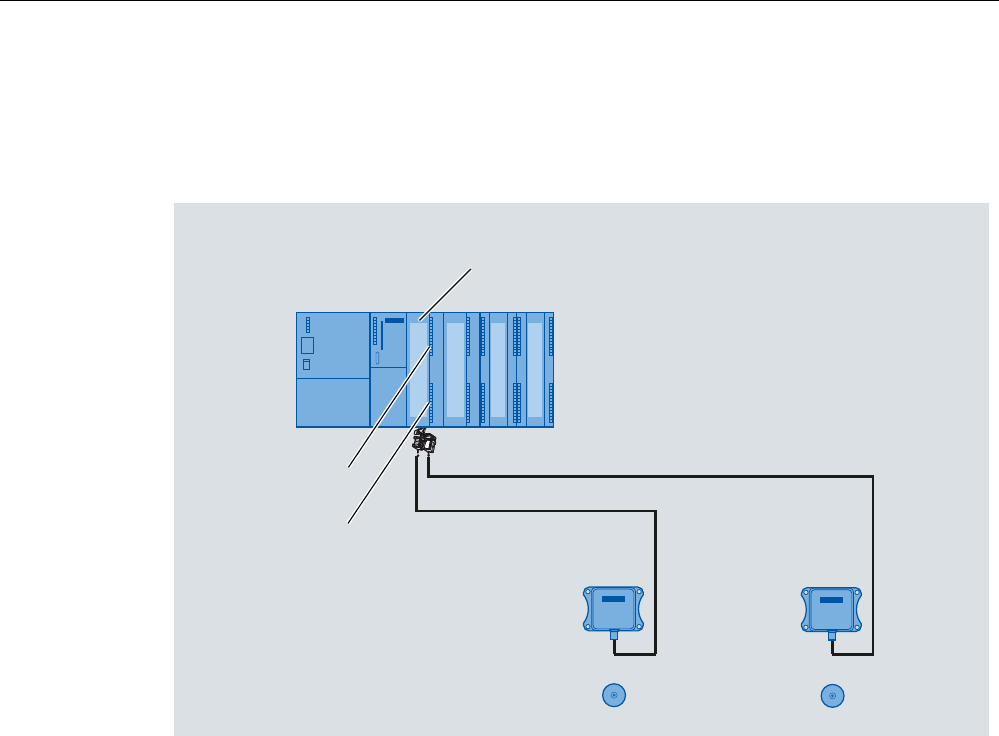
8.6.4 Configuration
Centralized configuration with SIMATIC S7-300
352),1(7b,2
0DVWHUPRGXOH
6,0$7,&b6
$60
FKDQQHO
$60
FKDQQHO
$60b
HJ
5)5
6
$GGLWLRQDOPRGXOHVIURPWKH
6UDQJHLQFO$60
7DJV0'6
HJ
5)5
Figure 8-19 Configuration of ASM 475 central
System integration
8.6 ASM 475
SIMATIC RF300
234 System Manual, 11/2009 - Zwischenstand 17.09.2009, A5E01642529-04
Distributed configuration with ET200M
$60
FKDQQHO
$60
FKDQQHO
$60b
HJ
5)5
(70
$GGLWLRQDOPRGXOHVIURPWKH
6UDQJHLQFO$60
HJ
5)5
7DJV0'6
HJLQWHUIDFHPRGXOH
Figure 8-20 Configuration of ASM 475 distributed
Reader connection system
The connecting cable has a length of 2 m (standard) and 5 m. Extensions up to 1000 m are
possible with the 6GT2891-0F plug-in cables.
&DEOHZLWKHQGVOHHYHV
JUD\
SLQN
\HOORZ
EURZQ
ZKLWH
VKLHOG
&DEOHVKLHOGH[SRVHG
$60VLGH 5HDGHUVLGH
JUHHQ
6/*FRQQHFWRU
6RFNHW
0SLQ
*7(ZLWKVWUDLJKW6/*FRQQHFWRUVWDQGDUG
Figure 8-21 Installation of connecting cable between ASM 475 and RF300 reader with RS 422

System integration
8.6 ASM 475
SIMATIC RF300
System Manual, 11/2009 - Zwischenstand 17.09.2009, A5E01642529-04 235
Cable installation
Signal Pin on
M12
connector
Cable Labeling
24 V DC 1 white 1 Reader 2
8 -16
TX - 2 brown 1 Reader 2
7-15
GND 3 Green 1 Reader 2
9-17
TX + 4 Yellow 1 Reader 2
6-14
RX + 5 Gray 1 Reader 2
4-12
RX - 6 Pink 1 Reader 2
5-13
Shield 8 + terminal
piece
-
Cable assignment for connection of an RF300 reader to ASM 475
8.6.5 Technical data
Table 8- 11 Technical data for ASM 475
Serial interface for SIMATIC S7-300 or
ET200M
I/O bus; cyclic and acyclic services
Communication 2 words cyclic/238 bytes acyclic
Command buffer in ASM 475 70 x 238 bytes per RF310R reader
Serial interface to the reader
Connector Via screw-type terminal on front connector
The front connector is not included in the scope
of supply.
Max. cable length Pre-assembled cables = 2 m, 5 m,
(up to 1000 m on request)
Readers that can be connected 2 x RF3xxR reader with RS422
parallel mode
Software functions
Programming Depending on the PROFIBUS DP master
Function blocks for SIMATIC S7 FC 45; FB 45; FC 55
Transponder addressing Direct access via addresses
Commands Initialize transponder, read data from
transponder, write data to transponder

System integration
8.6 ASM 475
SIMATIC RF300
236 System Manual, 11/2009 - Zwischenstand 17.09.2009, A5E01642529-04
Multitag mode No
S7 data structures via UDTs Yes
Power supply
Rated value 24 V DC
Permissible range 20.4 V to 28.8 V DC
Current consumption
Without reader for U = 24 V DC, max. 350 mA
With reader connected, max. 500 mA, per connected reader
Power dissipation of the module, typ. 2 Watts
Current consumption from I/O bus, max. 80 mA
Electrical isolation between S7-300 and RF300 Yes
Fuse 24 V for the reader Yes, electronic
Ambient temperature
During operation
Horizontal installation of SIMATIC
Vertical installation of SIMATIC
0 to +60 °C
0 to +40 °C
Transport and storage -40 to +70 °C
Dimensions (W x H x D) in mm 40 x 125 x 120
Weight, approx. 0.2 kg
System integration
8.7 RF170C
SIMATIC RF300
System Manual, 11/2009 - Zwischenstand 17.09.2009, A5E01642529-04 237
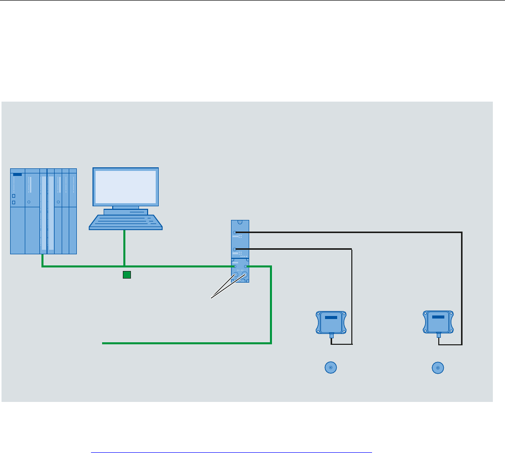
8.7 RF170C
Configured with RF170C
SIMATIC
RF170C
HJ
5)5
HJ
5)5
7DJV0'6
PROFIBUS or
PROFINET/Industrial Ethernet
Master module
SIMATIC S7
PROFINET/
Industrial Ethernet
or
Interface module
ET 200pro
9IRU
(7SUR5)&
DQGUHDGHU
PROFIBUS
Figure 8-22 Configuration of RF170C
For more detailed information, refer to SIMATIC RF170C Operating Instructions
(http://support.automation.siemens.com/WW/view/en/32622825).
System integration
8.8 RF180C
SIMATIC RF300
238 System Manual, 11/2009 - Zwischenstand 17.09.2009, A5E01642529-04
8.8 RF180C
Configured with RF180C
,QGXVWULDO(WKHUQHW
352),1(7
]%
5)5
]%
5)5
7DJV0'6
352),1(7b,2
0DVWHUPRGXOH
6,0$7,&b6
9IRU
5)&DQGUHDGHU
WRRWKHU352),1(7
EXVQRGHV
6,0$7,&
5)&
9WRRWKHU
352),1(7EXVQRGHV
Figure 8-23 Configuration of RF180C
For more detailed information, refer to SIMATIC RF180C Operating Instructions
(http://support.automation.siemens.com/WW/view/en/30012157).
System integration
8.9 RF182C
SIMATIC RF300
System Manual, 11/2009 - Zwischenstand 17.09.2009, A5E01642529-04 239
8.9 RF182C
Configuration with RF182C
,QGXVWULDO(WKHUQHW
]%
5)5
]%
5)5
7DJV0'6
352),1(7,2
9IRU
5)&DQGUHDGHU
7RDGGLWLRQDO352),1(7(WKHUQHWQRGHV
6,0$7,&
5)&
3&
PROFINET IO
Master module
SIMATIC S7
Figure 8-24 Configuration with RF182C
For more detailed information, refer to SIMATIC RF182C Operating Instructions
(http://support.automation.siemens.com/WW/view/en/38507897).
System integration
8.10 8xIQ-Sense
SIMATIC RF300
240 System Manual, 11/2009 - Zwischenstand 17.09.2009, A5E01642529-04
8.10 8xIQ-Sense
8.10.1 Features
Field of application
The 8xIQ-Sense module is the link between the RF310R with 8xIQ-Sense interface and
SIEMENS S7-300 and functions in the same manner as the communication module
(interface module). It can be operated centrally in an S7-300 or decentrally in an ET200M.
Figure 8-25 8xIQ-Sense interface module
8.10.2 Ordering data
Table 8- 12 Ordering data for 8xIQ-Sense and accessories
Order number
IQ-Sense SM338 for S7-300 and ET200M for the
connection of up to 8xIQ-Sense sensors
Optical sensors, ultrasonic sensors and RF
identification systems can be connected.
6ES7 3387XF000AB0
Table 8- 13 Ordering data for 8xIQ-Sense accessories
Order number
M12 cable plug, 4-pole, with 5 m black PUR cable, 4 x
0.34 mm2
3RX8000-0CB42-1AF0
M12 cable plug, 4-pole, with 10 m black PUR cable, 4 x
0.34 mm2
3RX8000-0CB42-1AL0
System integration
8.10 8xIQ-Sense
SIMATIC RF300
System Manual, 11/2009 - Zwischenstand 17.09.2009, A5E01642529-04 241
8.10.3 Indicators
Status displays
The 8xIQ-Sense module has the following LEDs:
A green LED, which has no function for RFID devices, and a red SF LED (system fault LED),
which indicates the diagnostic state of the module.
LEDs Labeling LED
status
Meaning
Green
LED per
channel
0…7 Has no function here
Illuminate
d
Module fault, sensor fault,
active teach-in operation,
external auxiliary voltage
missing
6)
60
[,46HQVH
;)$%
;
Red SF
Not
illuminate
d
No fault or no active teach-in
operation
System integration
8.10 8xIQ-Sense
SIMATIC RF300
242 System Manual, 11/2009 - Zwischenstand 17.09.2009, A5E01642529-04
8.10.4 Configuration
Centralized configuration with SIMATIC S7-300
$60
FKDQQHO
$60
FKDQQHO
[,46HQVH
6
$GGLWLRQDOPRGXOHVIURPWKH
6UDQJHLQFO[,46HQVH
5HDGHUZLWK
[,46HQVH
LQWHUIDFH
7DJV0'6
5HDGHUZLWK
[,46HQVH
LQWHUIDFH
Figure 8-26 Configuration of 8xIQ-Sense central
System integration
8.10 8xIQ-Sense
SIMATIC RF300
System Manual, 11/2009 - Zwischenstand 17.09.2009, A5E01642529-04 243
Distributed configuration with ET 200M
$60
FKDQQHO
$60
FKDQQHO
[,46HQVH
(70
$GGLWLRQDOPRGXOHVIURPWKH
6UDQJHLQFO[,46HQVH
5HDGHUZLWK
[,46HQVH
LQWHUIDFH
7DJV0'6
HJLQWHUIDFHPRGXOH
5HDGHUZLWK
[,46HQVH
LQWHUIDFH
Figure 8-27 Configuration of 8xIQ-Sense distributed
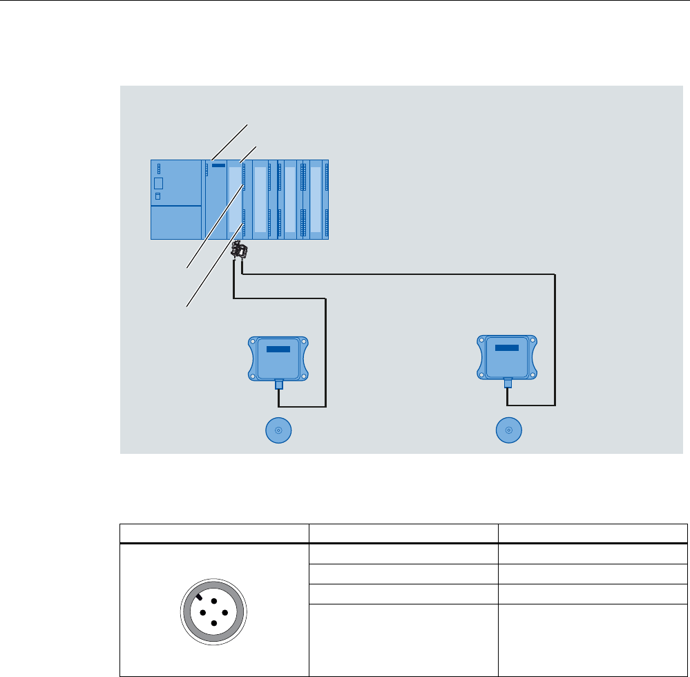
Table 8- 14 Pin assignment of RF310R with IQ-Sense interface
Pin Pin, device end, 4-pin M12 Assignment
1 IQ-Sense
2 Not used
3 IQ-Sense
4 Not used
System integration
8.10 8xIQ-Sense
SIMATIC RF300
244 System Manual, 11/2009 - Zwischenstand 17.09.2009, A5E01642529-04
Configuration of connecting cable from 8xIQ-Sense to RF310R
6/*6WHFNHU
0%XFKVH
5HDGHU6HLWH
,46HQVH6HLWH
EUDXQ
EODX
Figure 8-28 Cable and pin assignment of RF300 with IQ-Sense
8.10.5 Addressing
The address range of the 8xIQ-Sense module is 16 bytes I/O.
This is independent of the choice of channel profiles on the connected device
(i.e. the IQ profile IDs in HW Config).
Access to memory areas
A direct association exists between the number of the channel to which the IQ-Sense device
is connected (terminal) and the input and output data area of the module. Based on the
address range, the following addresses can be used to access the memory areas:
Address = module initial address + (channel no. x 2)
Example
Module initial address = 280
I/O address for channel 3: 286
System integration
8.10 8xIQ-Sense
SIMATIC RF300
System Manual, 11/2009 - Zwischenstand 17.09.2009, A5E01642529-04 245
,46HQVHGHYLFH
0
0ದ
0
0ದ
0
0ದ
0
0ದ
0
0ದ
0
0ದ
0
0ದ
0
0ದ
)URQW GRRULQWHULRU
FKDQQHO
7HUPLQDO
&KDQQHODGGUHVVHV
LQH[DPSOH
IRU,46HQVHGHYLFHV
&KDQQHOQR
FKDQQHO
FKDQQHO
FKDQQHO
FKDQQHO
FKDQQHO
FKDQQHO
FKDQQHO
,4
,4
,4
,4
,4
,4
,4
,4
/
0
IRU5)
,46HQVHGHYLFH
,46HQVHGHYLFH
,46HQVHGHYLFH
,46HQVHGHYLFH
,46HQVHGHYLFH
,46HQVHGHYLFH
,46HQVHGHYLFH
5)5
5)5
Figure 8-29 8xIQ-Sense module: Assignment of terminal pair to memory area
Note
A maximum of two read/write devices can be operated!
Each read/write device uses channel numbers 0 to 3 or 4 to 7.

System integration
8.10 8xIQ-Sense
SIMATIC RF300
246 System Manual, 11/2009 - Zwischenstand 17.09.2009, A5E01642529-04
8.10.6 Technical data
Voltages and currents
Rated supply voltage
Reverse polarity protection
24 V DC
yes
Galvanic isolation
Between the channels
Between channels and backplane bus
no
yes
Permissible potential difference
Between different circuits
75 V DC / 60 V AC
Insulation tested at 500 V DC
Current input
from the backplane bus
from L+ power supply
120 mA typical
500 mA max.
Module power loss 2.5 W typical
Module-specific data
Number of channels
Channels for RFID systems
8
2
Cable length, unshielded 50 m max.
Dimensions and weight
Dimensions w x h x d (mm) 40 x 125 x 120
Weight Approx. 235 g

SIMATIC RF300
System Manual, 11/2009 - Zwischenstand 17.09.2009, A5E01642529-04 247
System diagnostics 9
9.1 Error codes
Error codes of the RF300 readers
Flashing of red
LED on reader
Error code
(hexa-
decimal)
Description
00 00 no error
02 01 Presence error, possible causes:
The active command was not carried out completely
The tag has left the field while the command is being processed
Communication fault between reader and tag
05 05 Parameterization error, possible causes:
Unknown command
Incorrect parameter
Function not allowed
06 06 Air interface faulty
12 0C The tag memory cannot be written, possible causes:
Hardware fault (memory faulty)
Memory write-protected (corresponding OTP area has already
been written)
13 0D Error in the specified memory address (access attempted to non-
existent or non-accessible memory areas).
19 13 Buffer overflow: Insufficient buffer available in the reader for saving
the command
20 14 Major system fault (hardware fault)
21 15 Parameter assignment error: faulty parameter in RESET command
25 19 Previous command is still active
28 1C Antenna is already switched off/Antenna is already switched on
30 1E Incorrect number of characters in frame
31 1F Running command cancelled by "RESET" command

System diagnostics
9.2 Diagnostics functions
SIMATIC RF300
248 System Manual, 11/2009 - Zwischenstand 17.09.2009, A5E01642529-04
9.2 Diagnostics functions
9.2.1 Overview
Extended diagnostic functions with SIMATIC RF300 @ FB 45-Tabellen müssen noch hier reinverlinkt
werden
With SIMATIC RF300, extended diagnostic functions are available which simplify
commissioning and maintenance.
This diagnostics data is accessed using the SIMATIC function blocks via the SLG Status and
MDS Status commands. These two commands can each be called in various modes
(subcommands) for which corresponding data structures (UDTs) are defined.
Table 9- 1 In RF300 mode
Command Mode
(subcommand)
Meaning
01 Hardware and firmware configuration, parameterization statusSLG status
06 Communication error counter, current command status
01 Serial number of the tag (UID), memory configuration
EEPROM write-protection status
MDS status
02 Serial number of the tag (UID), HF field strength value,
communication error counter, presence counter (duration)
Overview of the diagnostic functions
Table 9- 2 In ISO mode
Command Mode
(subcommand)
Meaning
SLG status 01 Hardware and firmware configuration, parameterization status
MDS status 03 Serial number of the tag (UID), recognized tag type in the
field (number = tag - type, see reset parameter "ftim"),
memory configuration, write protect status (OTP), size and
number of blocks in the user memory
9.2.2 Reader diagnostics with SLG Status
The SLG STATUS command can be used to scan the status and diagnostics data of the
reader.

System diagnostics
9.2 Diagnostics functions
SIMATIC RF300
System Manual, 11/2009 - Zwischenstand 17.09.2009, A5E01642529-04 249
SLG STATUS (mode 01), corresponds to UDT 110
Name Type Possible values Comment
hardware char (31 to 38 hex) Type of hardware
hardware_version word
0 to FF hex
0 to FF hex
HW version
= Version (high byte): Unused
= Version (low byte)
loader_version word
0 to FF hex
0 to FF hex
Version of loader
= Version (high byte)
= Version (low byte)
firmware char 0 to FF hex Type of firmware
firmware_version word
0 to FF hex
0 to FF hex
Firmware version
= Version (high byte)
= Version (low byte)
driver char
31 hex
Type of driver
3964R
driver_version word
0 to FF hex
0 to FF hex
Version of driver
= Version (high byte)
= Version (low byte)
interface byte
01 hex
02 hex
Interface type
= RS422
= RS232 (only RF380R)
baud byte
01 hex
03 hex
05 hex
Baud rate
= 19.2 Kbaud
= 57.6 Kbaud
= 115,2 Kbaud
This variable is only provided for the RF380R. Users are therefore able to
check the output power actually set. An incorrect value in the parameter
"distance_limiting" of the RESET message frame results in the default setting
"05".
Transmit power
02 hex 0.5 W
03 hex 0.75 W
04 hex 1,0
05 hex 1.25 W (default)
06 hex 1.5 W
07 hex 1.75 W
distance_limiting_SLG byte
08 hex 2.0 W
multitag_SLG byte
01 hex
Number of MDSes (Multitag/Bulk) that can be processed in
the antenna field
= Single tag mode

System diagnostics
9.2 Diagnostics functions
SIMATIC RF300
250 System Manual, 11/2009 - Zwischenstand 17.09.2009, A5E01642529-04
Name Type Possible values Comment
field_ON_time_SLG byte 00 hex
01 hex
03 hex
04 hex
05 hex
06 hex
07 hex
RF300 transponder
ISO transponder (non-specific)
ISO my-d (Infineon SRF 55V10P)
ISO (Fujitsu MB89R118)
ISO I-Code SLI (Philips SL2 ICS20)
Tag-it HFI (Texas Instruments)
ISO (ST LRI2K)
status_ant byte
01 hex
02 hex
Status of antenna
= Antenna On
= Antenna Off
MDS_control byte
00 hex
01 hex
Presence mode
= Operation without presence message
= Operation with presence message
SLG STATUS (mode 06), corresponds to UDT 280
Name Type Possible values Comment
FZP byte 0 to FF hex = Error counter, passive (errors during idle time)
ABZ byte 0 to FF hex = Abort counter
CFZ byte 0 to FF hex = Code error counter
SFZ byte 0 to FF hex = Signature error counter
CRCFZ byte 0 to FF hex = CRC error counter
BSTAT byte 0 to FF hex = Current command status
ASMFZ byte 0 to FF hex = Interface problems to host (ASM/PC) parity, BCC,
frame error
Note
All counter values are reset after reading (= SLG STATUS command executed).
Explanations:
● "FZP": Counts interference pulses when communication is not taking place with a
transponder. (e.g. EMC interference caused by contactors, motors, etc.). However,
counter values can also be generated when a tag is located at the edge of the field even
when there is no external interference.
● "ABZ", "CFZ", "SFZ" and "CRCFZ" are counters for protocol errors which may occur
during reader-tag communication. This can be caused by unsuitable reader/tag
positioning (e.g. tag on field boundary, several data carriers in the field) or an external
electromagnetic interference.
To ensure clear diagnosis of the quality of communication, it is recommended that an SLG
STATUS command (mode 06) is executed following receipt of the presence command to
reset the error counter.

System diagnostics
9.2 Diagnostics functions
SIMATIC RF300
System Manual, 11/2009 - Zwischenstand 17.09.2009, A5E01642529-04 251
The protocol error counters are not mutually independent. If a code error (CFZ) occurs, this
will cause a signature (SFZ) or CRC- (CRCFZ) error.
● "BSTAT" is the status for the most recently executed command. A value other than 0
means that the previous command was repeated by the reader due to faults (see above).
● "ASMFZ" signals line-conducted communication interference between the communication
module (ASM) and the reader. Faults of this type can be caused by contact problems on
the connector or the cable connection.
9.2.3 Transponder diagnostics with MDS Status
The MDS STATUS command can be used to scan the status and diagnostics data of the
transponder that is located within the antenna field.
MDS Status (mode 01), corresponds to UDT 260, only for RF300 tags
Name Type Possible values Comment
UID array[1…8] byte
0000000055555555
hex to 00000000
FFFFFFFF hex
Unique identifier
= b0-31: 4 byte TAG ID, b32-63: 0
MDS_type byte
01 hex
02 hex
03 hex
04 hex
Tag memory configuration
= Transponder without FRAM
= Transponder with FRAM 8 KB
= Transponder with FRAM 32 KB
= Transponder with FRAM 32 KB
Lock_state byte 0 to FF hex EEPROM write protection status
(use graphic from UDT260 here)
MDS Status (mode 02), corresponds to UDT 270, only for RF300 tags
Name Type Possible values Comment
UID array[1…8] byte
0000000055555555
hex to
00000000FFFFFFFF
hex
Unique identifier
= b0-31: 4 byte TAG ID, b32-63: 0
LFD byte 0 to FF hex = Value for field strength determined in the tag
FZP byte 0 to FF hex = Error counter (passive) ➙ errors during idle time
FZA byte 0 to FF hex = Error counter (active)
ANWZ byte 0 to FF hex = Presence counter

System diagnostics
9.2 Diagnostics functions
SIMATIC RF300
252 System Manual, 11/2009 - Zwischenstand 17.09.2009, A5E01642529-04
Note
All counter values are reset when the tag exits the field or when the antenna is switched off.
Explanations:
● "LFD" is a value for the field strength that is determined in the transponder. The lower the
value, the higher the field strength.
● "FZP" counts fault pulses when communication with a transponder is not taking place
(e.g. electromagnetic interference caused by contactors, motors, etc.). Counter values
can also be generated when a transponder is located at the edge of the field even when
there is no external interference.
● "FZA" counts errors that can occur during reader-to-transponder communication. This can
be caused by unsuitable reader/transponder positioning (e.g. transponder on field
boundary, several data carriers in the field) or external electromagnetic interference.
● "ANWZ" is the value for the time that the transponder remains in the field before the MDS
STATUS command (mode 02) is executed. A time step is 10 ms. The maximum time that
can be recorded is therefore 2.5 s.
MDS STATUS for ISO mode (mode 03) corresponds to UDT 230
Table 9- 3 MDS STATUS for ISO mode
Name Type Possible values Comment
UID array[1…8] byte
000000000
0000000 hex to
FFFFFFFF
FFFFFFFF hex
Unique identifier
=8 byte UID, MSB first
MDS_type byte
01 hex
03 hex
04 hex
05 hex
06 hex
07 hex
Tag type (vendor, identification)
= ISO general (non-specific or unknown)
= my-d (Infineon)
= MB89R118 (Fujitsu)
= I-Code SLI (NXP)
= Tag-it HFI (Texas Instruments)
= LRI2K (ST)
IC_version byte 0 to FF hex Chip version
size byte 0 to FF hex Memory size in bytes
Depending on tag type, e.g. my-d: 992 bytes

System diagnostics
9.2 Diagnostics functions
SIMATIC RF300
System Manual, 11/2009 - Zwischenstand 17.09.2009, A5E01642529-04 253
Name Type Possible values Comment
lock_state byte 0 to FF hex Lock status, OTP information:
one bit is used per block (4 x 4 bytes or 2 x 8 bytes) (bit = 1:
block is locked)
e.g. 01 = Block 1 of address FF80 - FF83 is locked or
03 = Block 1 and 2 of address FF80 - FF87 are locked,
e.g. for the Philips SL2 ICS20 (MDS D124, D160 or D100).
This chip provides a usable memory (112 bytes EEPROM)
from address 0000 - 006F (total OTP area 0060 - 006F). In
this memory, the locked area corresponds to the addresses
0060 - 0063 or 0060 - 0067
block_size byte 0 to FF hex Block size of the transponder
Depending on tag type, e.g. my-d: 4 bytes
nr_of_blocks byte 0 to FF hex Number of blocks
Depending on tag type, e.g. my-d: 248
SIMATIC RF300
System Manual, 11/2009 - Zwischenstand 17.09.2009, A5E01642529-04 255
Appendix A
A.1 Certificates and approvals
Certificate Description
CE Approval to R&TTE
Notes on CE marking
The following applies to the system described in this documentation:
The CE marking on a device is indicative of the corresponding approval:
DIN ISO 9001 certificate
The quality assurance system for the entire product process (development, production, and
marketing) at Siemens fulfills the requirements of ISO 9001 (corresponds to EN29001:
1987).
This has been certified by DQS (the German society for the certification of quality
management systems).
EQ-Net certificate no.: 1323-01
Certifications for the United States, Canada, and Australia
Safety
One of the following markings on a device is indicative of the corresponding approval:
Underwriters Laboratories (UL) per UL 60950 (I.T.E) or per UL 508 (IND.CONT.EQ)
Underwriters Laboratories (UL) according to Canadian standard C22.2 No. 60950
(I.T.E) or C22.2 No. 142 (IND.CONT.EQ)
Underwriters Laboratories (UL) according to standard UL 60950, Report E11 5352 and
Canadian standard C22.2 No. 60950 (I.T.E) or UL508 and C22.2 No. 142
(IND.CONT.EQ)
UL recognition mark
Appendix
A.1 Certificates and approvals
SIMATIC RF300
256 System Manual, 11/2009 - Zwischenstand 17.09.2009, A5E01642529-04
One of the following markings on a device is indicative of the corresponding approval:
Canadian Standard Association (CSA) per Standard C22.2. No. 60950 (LR 81690) or
per C22.2 No. 142 (LR 63533)
Canadian Standard Association (CSA) per American Standard UL 60950 (LR 81690) or
per UL 508 (LR 63533)
EMC
USA
Federal Communications
Commission
Radio Frequency
Interference Statement
This equipment has been tested and found to comply with the limits for a
Class A digital device, pursuant to Part 15 of the FCC Rules. These limits
are designed to provide reasonable protection against harmful
interference when the equipment is operated in a commercial
environment. This equipment generates, uses, and can radiate radio
frequency energy and, if not installed and used in accordance with the
instruction manual, may cause harmful interference to radio
communications. Operation of this equipment in a residential area is likely
to cause harmful interference in which case the user will be required to
correct the interference at his own expense.
Shielded Cables Shielded cables must be used with this equipment to maintain compliance
with FCC regulations.
Modifications Changes or modifications not expressly approved by the manufacturer
could void the user's authority to operate the equipment.
Conditions of Operations This device complies with Part 15 of the FCC Rules. Operation is subject
to the following two conditions: (1) this device may not cause harmful
interference, and (2) this device must accept any interference received,
including interference that may cause undesired operation.
CANADA
Canadian Notice This Class A digital apparatus complies with Canadian ICES-003.
AUSTRALIA
This product meets the requirements of the AS/NZS 3548 Norm.

Appendix
A.2 Accessories
SIMATIC RF300
System Manual, 11/2009 - Zwischenstand 17.09.2009, A5E01642529-04 257
A.2 Accessories
CD "RFID Systems Software & Documentation"
The CD contains:
● FB/FC for SIMATIC, 3964R
● Driver for DOS/Windows 95/NT/2000/XP
● C libraries
● PC demonstration program
● RFID documentation in PDF format, especially RFID system manuals, programming
instructions and operating instructions
The "RFID Systems Software & Documentation" CD has a user-friendly interface based on
HTML. After Start.exe has been called, a window for selecting the RFID system appears:
● RF300
● RF600
● RF-MANAGER
● MOBY
● CM/ASM
After selecting the RFID system, you can navigate to the required information.
Product Order number
CD "RFID Systems Software & Documentation" 6GT2 080-2AA10
Note
Notes on "RFID system software" and licensing
When purchasing a communication module or an interface module, no software or
documentation is supplied. The "RFID Systems Software & Documentation" CD-ROM
contains all available FBs/FCs for the SIMATIC, C libraries, demo programs, etc. and needs
to be ordered separately. In addition, the CD-ROM contains the complete RFID
documentation (German, English and French) in PDF format.
The purchase of a communication module or an interface module includes a payment for the
use of the software, including documentation, on the "RFID Systems Software &
Documentation" CD-ROM and the purchaser acquires the right to make copies (copy
license) insofar as they are required as part of the customer-specific application or
development for the plant.
The enclosed contract pertaining to the use of software products against a one-off payment
shall apply in addition.
Appendix
A.3 Connecting cable
SIMATIC RF300
258 System Manual, 11/2009 - Zwischenstand 17.09.2009, A5E01642529-04
A.3 Connecting cable
In the following chapter, you will find an overview of the connecting cables between the
readers and communication modules or PCs.
A.3.1 Reader RF3xxR (RS422) with ASM 452/ASM 473
A reader always occupies two M12 connection sockets on the ASM 452/ASM 473
A pre-assembled cable therefore ensures easy connection of the reader (see figure below).
The connecting cable has a length of 2 m (standard) and 5 m. Extensions up to 1000 m are
possible with the 6GT2891-0F plug-in cables.
JUD\
JUHHQ
ZKLWH
EURZQ
\HOORZ
SLQN
VKLHOG
7ZRSLQ0
FLUFXODUFRQQHFWRUV
$60VLGH 5HDGHUVLGH
0SLQ
;
;
;
;
;
;
;
; ;
;
Figure A-1 Connecting cable between ASM 452/473 and RF3xxR reader with RS422 (6GT2891-
1CH20)
A.3.2 Reader RF3xxR (RS422) with ASM 456/RF170C/RF180C
0FRQQHFWRU
PDOH
5HDGHUVLGH
$60VLGH
/
Figure A-2 Connecting cable between ASM 456, RF170C, RF180C and reader RF3xxR (RS422)
Appendix
A.3 Connecting cable
SIMATIC RF300
System Manual, 11/2009 - Zwischenstand 17.09.2009, A5E01642529-04 259
Table A- 1 Ordering data
Length L Order number
2 m 6GT2891-0FH20
5 m 6GT2891-0FH50
10 m 6GT2891-0FN10
20 m 6GT2891-0FN20
50 m 6GT2891-0FN50
A.3.3 Reader RF3xxR (RS422) with ASM 475
Reader connection system
The connecting cable has a length of 2 m (standard) and 5 m. Extensions up to 1000 m are
possible with the 6GT2891-0F plug-in cables.
&DEOHZLWKHQGVOHHYHV
JUD\
SLQN
\HOORZ
EURZQ
ZKLWH
VKLHOG
&DEOHVKLHOGH[SRVHG
$60VLGH 5HDGHUVLGH
JUHHQ
6/*FRQQHFWRU
6RFNHW
0SLQ
*7(ZLWKVWUDLJKW6/*FRQQHFWRUVWDQGDUG
Figure A-3 Installation of connecting cable between ASM 475 and RF300 reader with RS 422
Appendix
A.3 Connecting cable
SIMATIC RF300
260 System Manual, 11/2009 - Zwischenstand 17.09.2009, A5E01642529-04
A.3.4 RF310R and IQ-Sense
The connecting cable is available in lengths of 5 m (standard) and 10 m.
6/*6WHFNHU
0%XFKVH
5HDGHU6HLWH
,46HQVH6HLWH
EUDXQ
EODX
Figure A-4 Configuration of connecting cable from 8xIQ-Sense to RF310R
Length Order number
5 m 3RX8000-0CB42-1AF0
10 m 3RX8000-0CB42-1AL0
A.3.5 Reader RF380R (RS232) - PC
The connecting cable (6GT2891-0KH50) is 5 m long.
Special feature of the cable: additional branch for the power supply.
5HDGHUVLGH
SROH
0SLQ
68%'SLQ3&
6RFNHW
Figure A-5 Connecting cable RF380R (RS232) to the PC
Suitable power supply unit: e.g. wide-range power supply unit

Appendix
A.4 Ordering data
SIMATIC RF300
System Manual, 11/2009 - Zwischenstand 17.09.2009, A5E01642529-04 261
Table A- 2 Ordering data for wide-range power supply unit
Wide-range power supply unit for SIMATIC RF-systems
(100 - 240 V AC / 24 V DC / 3 A)
with 2 m connecting cable with country-specific plug
EU: 6GT2898-0AA00
UK: 6GT2898-0AA10
US: 6GT2898-0AA20
A.4 Ordering data
RF300 components
Table A- 3 RF300 reader
Readers Description Order number
RF310R
(IQ-Sense)
With IQ-Sense interface
IP 67
Operating temperature: -25 °C to +70 °C
Dimensions: 55 x 75 x 30 (L x W x H, in mm)
with integrated antenna
6GT2801-0AA00
RF310R
(RS422)
With RS422 interface (3964R)
IP 67
Operating temperature: -25 °C to +70 °C
Dimensions: 55 x 75 x 30 (L x W x H, in mm)
with integrated antenna
ISO 15693 compatible
6GT2801-1AB10
RF340R With RS422 interface (3964R)
IP 67
Operating temperature -25 °C … +70 °C
Dimensions 75 x 91 x 41 (L x W x H in mm)
with integrated antenna
6GT2801-2AB10
RF350R With RS422 interface (3964R)
IP 65
Operating temperature: -25 °C … +70 °C
Dimensions: 75 x 96 x 41 (L x W x H, in mm)
For pluggable antennas ANT 1, ANT 12, ANT 18, ANT 30
6GT2801-4AB10
RF380R With RS422 interface (3964R)
IP 67
Operating temperature: -25 °C … +70 °C
Dimensions: 160 x 96 x 40 (L x W x H, in mm)
with integrated antenna
ISO 15693 compatible
6GT2801-3AB10

Appendix
A.4 Ordering data
SIMATIC RF300
262 System Manual, 11/2009 - Zwischenstand 17.09.2009, A5E01642529-04
Table A- 4 Antennae
Antenna Description Order number
ANT 1 IP67
Operating temperature: -25 °C to +70 °C
Dimensions: 75 x 75 x 20 (L x W x H, in mm)
6GT2398-1CB00
ANT 12 IP67
Operating temperature: -25 °C to +70 °C
Dimensions: M18 x 1.0 x 55
6GT2 398-1CC00
ANT 18 IP67 (front)
Operating temperature -25 °C to +70 °C
Dimensions: M18 x 50 (Ø x L in mm)
6GT2398-1CA00
ANT 30 IP67 (front)
Operating temperature -25 °C to +70 °C
Dimensions: M30 x 58 (Ø x L in mm)
6GT2398-1CD00
Table A- 5 RF300 transponder
RF300 transponder Description Order number
RF320T IP67
Memory size: 20 byte EEPROM
Operating temperature: -25 °C to +85 °C
Dimensions: 27 mm x 4 mm (Ø x H in mm)
6GT2800-1CA00
RF340T IP68
Memory size: 8 KB FRAM
Operating temperature: -25 °C to +85 °C
Dimensions: 48 x 25 x 15 (L x W x H, in mm)
6GT2800-4BB00
RF350T IP68
Memory size: 32 KB FRAM (read/write) and 4 byte EEPROM (read
only)
Operating temperature: -25 °C … +85 °C
Dimensions: 50 x 50 x 20 (L x W x H, in mm)
6GT2800-5BD00
RF360T IP67
Memory size: 8 KB FRAM (read/write) and 4 byte EEPROM (read only)
Operating temperature: -25 °C … +75 °C
Dimensions: 85.8 x 54.8 x 2.5 (L x W x H, in mm)
6GT2800-4AC00
RF370T
(32 KB FRAM)
IP68
Memory size: 32 KB FRAM
Operating temperature: -25 to +85 °C
Dimensions: 75 x 75 x 40 (L x W x H, in mm)
6GT2800-5BE00

Appendix
A.4 Ordering data
SIMATIC RF300
System Manual, 11/2009 - Zwischenstand 17.09.2009, A5E01642529-04 263
RF300 transponder Description Order number
RF370T
(64 KB FRAM)
IP68
Memory size: 64 KB FRAM
Operating temperature: -25 °C to +85 °C
Dimensions: 75 x 75 x 40 (L x W x H, in mm)
6GT2800-6BE00
RF380T IP68
Memory size 32 KB FRAM (read/write) and 4 byte EEPROM
Operating temperature -25 … +200 °C (cyclic)
Dimensions: 114 x 83 (Ø x H in mm)
6GT2800-5DA00
Table A- 6 ISO transponder
ISO transponder Description Order number
MDS D100 IP68
Memory size: 112 byte EEPROM
Operating temperature: -25 … +80 °C
Dimensions: 85.6 x 54 x 0.9 (L x W x H, in mm)
ISO card
6GT2600-0AD10
MDS D124 IP67
Memory size: 112 byte EEPROM user memory
Operating temperature: -25 … +125 °C
Dimensions: 27 mm x 4 mm (Ø x H in mm)
6GT2600-0AC00
MDS D139 IP68
Memory size: 112-byte user memory
Operating temperature: up to +200 °C/+220 °C [heat-resistant (r/w)]
Dimensions: 85 x 15 (Ø x H in mm)
6GT2600-0AA10
MDS D160 IP68 (24 hours, 2 m, +20 °C)
Memory size: 112 byte user memory
Operating temperature: -25 °C...+70 °C
Dimensions: 16 x 3 ±0.1 (Ø x H in mm)
Laundry tag for cyclical applications (r/w)
6GT2600-0AB10
MDS D324 IP67
Memory size: 992 byte EEPROM user memory
Operating temperature: -25 °C...+125 °C
Dimensions: 27 x 4 (Ø x H in mm)
6GT2600-3AC00
MDS D421 IP67/x9K
Memory size: 2000 byte user memory
Operating temperature: –25 °C to +85 °C
Dimensions: 10 x 4.5 (Ø x H in mm)
6GT2600-4AE00
MDS D424 IP67
Memory size: 992 byte EEPROM user memory
Operating temperature: -25 °C ...+125 °C
Dimensions: 27 x 4 (Ø x H in mm)
6GT2600-4AC00

Appendix
A.4 Ordering data
SIMATIC RF300
264 System Manual, 11/2009 - Zwischenstand 17.09.2009, A5E01642529-04
ISO transponder Description Order number
MDS D428 IP68; IP x9K
Memory size: 2000 byte FRAM user memory
Operating temperature: -25 °C ...+85 °C
Dimensions (D x H): 18 mm x 20 mm (without thread), tolerance 1 mm;
M8 thread
6GT2600-4AK00
MDS D460 IP68
Memory size: 2000 byte FRAM user memory
Operating temperature: -25 °C ...+85 °C
Dimensions: 16 x 3 ±0.1 (Ø x H in mm)
6GT2600-4AB00
Table A- 7 Communication modules/interface modules
ASM/
communication
module
Description Order number
ASM 452 for PROFIBUS DP-V1,
1x RF3xxR with RS422 interface
without connector for 24 V DC and PROFIBUS
6GT2002-0EB20
ASM 456 for PROFIBUS DP-V1
For connecting as many as 2 readers
6GT2002-0ED00
ASM 473 1x RF3xxR reader with RS422 can be connected 6GT2002-0HA10
ASM 475 For SIMATIC S7
2 x readers RF3xxR with RS422 can be connected in parallel without a
front connector
6GT2002-0GA10
Communication module, 1 unit 6GT2002-0HD00 RF170C
Connection module, 1 unit 6GT2002-1HD00
RF180C communication module
max. 2 SLGs or readers can be connected
6GT2002-0JD00
Connection block M12, 7/8" PN 6GT2002-1JD00
RF180C
Push-pull connection block, RJ45 6GT2002-2JD00
RF182C communication module
Max. 2 SLGs or readers can be connected
6GT2002-0JD10
Connection block M12, 7/8'' (5-pole) 6GT2002-1JD00
Connection block M12, 7/8'' (4-pole) 6GT2002-4JD00
RF182C
Push-pull connection block, RJ45 6GT2002-2JD00
8xIQ-Sense ● IQ-Sense SM338 for S7-300 and ET200M for the connection of up to
8xIQ-Sense sensors
● Optical sensors, ultrasonic sensors and RF identification systems can be
connected.
6ES7 3387XF000AB0

Appendix
A.4 Ordering data
SIMATIC RF300
System Manual, 11/2009 - Zwischenstand 17.09.2009, A5E01642529-04 265
Accessories
Table A- 8 Accessories for RF300 reader
Readers Accessories Order number
RF380R Connecting cable RS232 to PC 6GT2891-0KH50
Table A- 9 Accessories for RF300 tags
Tag Accessories Order number
Spacers 6GT2190-0AA00 RF360T
Fixing pocket 6GT2190-0AB00
Holder (short version) 6GT2090-0QA00
Holder (long version) 6GT2090-0QA00-0AX3
Covering hood 6GT2090-0QB00
RF380T
Universal holder 6GT2590-0QA00
Table A- 10 Accessories for ISO tags
MDS Accessories Order number
Spacers 6GT2190-0AA00
Fixing pocket 6GT2190-0AB00
MDS D100
Fixing pocket
(cannot be mounted directly on metal)
6GT2390-0AA00
MDS D139 Spacer [85 mm x 30 mm (Ø x H in mm)] 6GT2690-0AA00
Table A- 11 Connecting cable accessory - ASM/communication module to reader
ASM - Reader Description Order number
Length
2 m 6GT2891-1CH20
ASM 452/
ASM 473
and reader
RF3xxR with
RS422
5 m 6GT2891-1CH50
Length
2 m 6GT2891-0FH20
5 m 6GT2891-0FH50
10 m 6GT2891-0FN10
20 m 6GT2891-0FN20
ASM
456/RF170C/
RF180C
and reader
RF3xxR
(RS422)
50 m 6GT2891-0FN50
Length ASM 475
and reader 2 m 6GT2891-0EH20
Appendix
A.5 Service & Support
SIMATIC RF300
266 System Manual, 11/2009 - Zwischenstand 17.09.2009, A5E01642529-04
ASM - Reader Description Order number
RF3xxR
(RS422) 5 m 6GT2891-0EH50
Length
5 m 3RX8000-0CB42-1AF0
8xIQ-Sense
and RF310R
10 m 3RX8000-0CB42-1AL0
Table A- 12 RFID accessories, general
RFID accessories, general Order number
CD "RFID Systems Software & Documentation" 6GT2 080-2AA10
Wide-range power supply unit for SIMATIC RF systems
(100 - 240 V AC/24 V DC/3 A)
with 2 m plug-in cable with country-specific connector
EU: 6GT2898 0AA00
UK: 6GT2898 0AA10
US: 6GT2898 0AA20
A.5 Service & Support
Contact partner
If you have any further questions on the use of our products, please contact one of our
representatives at your local Siemens office.
The addresses are found on the following pages:
● On the Internet (www.siemens.com/automation/partner)
● In Catalog CA 01
● In Catalog FS 10 specially for factory automation sensors
Technical Support
You can access technical support for all IA/DT projects via the following:
● Phone: + 49 (0) 180 5050 222
(€ 0.14 /min. from the German landline network, deviating mobile communications prices
are possible)
● E-mail (mailto:support.automation@siemens.com)
● Internet: Online support request form: (www.siemens.com/automation/support-request)
Service & support for industrial automation and drive technologies
You can find various services on the Support homepage
(www.siemens.com/automation/service&support) of IA/DT on the Internet.
There you will find the following information, for example:

Appendix
A.5 Service & Support
SIMATIC RF300
System Manual, 11/2009 - Zwischenstand 17.09.2009, A5E01642529-04 267
● Our newsletter containing up-to-date information on your products.
● Relevant documentation for your application, which you can access via the search
function in "Product Support".
● A forum for global information exchange by users and specialists.
● Your local contact for IA/DT on site.
● Information about on-site service, repairs, and spare parts. Much more can be found
under "Our service offer".
RFID homepage
For general information about our identification systems, visit RFID homepage
(www.siemens.com/simatic-sensors/rf).
Technical documentation on the Internet
A guide to the technical documentation for the various products and systems is available on
the Internet:
SIMATIC Guide manuals (www.siemens.com/simatic-tech-doku-portal)
Online catalog and ordering system
The online catalog and the online ordering system can also be found on the A&D Mall
homepage. (www.siemens.com/automation/mall)
Training center
We offer appropriate courses to get you started. Please contact your local training center or
the central training center in
D-90327 Nuremberg.
Phone: +49 (0) 180 523 56 11
(€ 0.14 /min. from the German landline network, deviating mobile communications prices are
possible)
For information about courses, see the SITRAIN homepage (www.sitrain.com).
SIMATIC RF300
System Manual, 11/2009 - Zwischenstand 17.09.2009, A5E01642529-04 269
Glossary
SIMATIC RF300
System Manual, 11/2009 - Zwischenstand 17.09.2009, A5E01642529-04 271
Index
8
8xIQ-Sense module
Addressing, 244
Indicators, 241
Ordering data, 241
A
Antennae
Minimum clearances, 121
Application Planning
SIMATIC RF300, 27
Approvals, 255
ASM 452
Configuration, 214
Indicators, 213
Operating mode, 215
Ordering data, 212
Pin assignments, 213
PROFIBUS address and terminating resistor, 217
PROFIBUS configuration, 214
Reader connection system, 215
ASM 473
Design and function, 221
Dimensions, 228
Features, 221
Hardware configuration, 226
Maximum configuration of an ET 200X, 226
Notes on operation, 224
Ordering data, 222
Pin assignments, 223
Reader connection system, 226
Technical specifications, 227
ASM 475
Assignment for connecting cable, 234, 259
Cable installation, 235
Design and function, 229
Function of the LEDs, 231
Indicators, 231
Ordering data, 230
Pin assignment, 234, 259
Status display with LEDs, 232
C
Cabinet configuration, 92
Cable, 258
Reader - ASM, 258
Shielding, 96
Calculation example, 39
Certificates, 255
Chemical resistance of the MDS
MDS D139, 83
MDS D160, 86
Combinations
Reader-tag, 18
Communication modules, 17, 209
Communication time
Calculating, 37
Connecting cable
Reader-communication module/ASM/PC, 258
Contact partner, 266
Conventions, 12, 20
Coupling paths, 91
Courses, 267
Customer benefits, 21
D
Data transmission rate
MDS D100, 55
MDS D124, 56
MDS D139, 57
MDS D160, 58
MDS D324, 59, 60, 61, 62
RF320T, 49
RF340T, 50
RF350T, 51
RF360T, 52
RF370T, 53
RF380T, 54
Design
System Manual, 11
Detection area, 35
Diagnostic functions
Transponder, 251
Direction of motion
Transponder, 35
Display elements

Index
SIMATIC RF300
272 System Manual, 11/2009 - Zwischenstand 17.09.2009, A5E01642529-04
RF310R reader with IQ-Sense interface, 101
RF310R reader with RS422 interface, 105, 110,
115, 126
RF340R reader, 110
Dwell time
Transponder, 36
Dynamic mode, 36
Dwell time of the transponder, 36
E
Electromagnetic compatibility
Coupling paths, 91
Electromagnetic interference, 89
EMC Directives
Propagation of electromagnetic interference, 89
EMC Guidelines, 256
Avoiding interference, 94
Basic Rules, 88
Cabinet configuration, 92
Cable shielding, 97
Definition, 87
Equipotential bonding, 95
Overview, 86
Equipotential bonding, 95
Error codes
Readers, 247
F
FC 45, 248
Features of ASM 452 interface module
Area of application, 211
Field data
RF310R reader, 44
Fields of application, 20
Fixing pocket
for MDS D100, 174
Flush-mounting
of transponders and readers, 64
H
High-performance, 16
I
Inductive alternating field, 27
Input parameter, 209
Installation
Several readers, 64
Installation guidelines, 62
Interface modules, 209
Interference sources
Electromagnetic, 90
IQ-Sense interface
Pin assignment, 100, 243
ISO functionality, 99
L
LEDs
For MOBY, 223
for PROFIBUS DP, 223
Low-performance, 16
M
Main applications, 20
MDS STATUS, 248
Medium-performance, 16
Memory configuration of the RF300 tags, 134
Metal
Influence on the transmission window, 66
Metal-free area
Reader RF310R, 101, 106
Reader RF340R, 110, 127
Transponder RF320T, 136
Transponder RF340T, 140
Transponder RF350T, 143
Transponder RF360T, 147
Transponder RF370T, 152
Transponder RF380T, 159
Minimum clearances
Antenna to antenna, 121
Minimum distance
Antenna to antenna, 48
Reader to reader, 48
Transponder to transponder, 47
O
Ordering data, 261
8xIQ-Sense module, 241
Antennae, 262
Interface modules/communication Modules, 264
Overview, 261
Readers, 261
RF300 transponder, 262
RF310R with IQ-Sense, 100

Index
SIMATIC RF300
System Manual, 11/2009 - Zwischenstand 17.09.2009, A5E01642529-04 273
P
Parameterization
Function blocks, 209
PROFIBUS cable
Stripped lengths, 228
R
Read/write distance, 27
Reader RF310R
Display elements, 101
Metal-free area, 101, 106
Pin assignment of IQ-Sense interface, 100
Reader RF340R
Metal-free area, 110, 127
Readers, 99
Mounting, 64
Reducing interference due to metal, 63
Reduction of field data by metal
RF340R, 68, 69
RF350R with ANT 1, 70, 71, 72
RF350R with ANT 18, 72, 73
RF350R with ANT 30, 74
RF380R, 67, 75, 76
Resistance to chemicals
Transponder, 77
RF310R reader, 100, 104, 113, 125
Characteristics, 100, 104, 113, 125
Minimum distance, 102, 106
Pin assignment of IQ-Sense interface, 243
RF340R reader, 109
Characteristics, 109
RF370T transponder/32 KB FRAM
Technical specifications, 154
RFID systems
Overview, 15
S
Selection criteria
SIMATIC RF300 components, 27
Shielding, 97
SIMATIC RF300
Diagnostic functions, 248
SLG STATUS, 248
Spacers, 175
Static mode, 35
Dwell time of the transponder, 36
System diagnostics
MDS status, 251
Overview, 248
System overview
RFID systems, 15
T
Technical documentation
On the Internet, 267
Technical specifications
RF370T transponder/32 KB FRAM, 154
Transponder RF320T, 138
Transponder RF340T, 141
Transponder RF350T, 144, 150
Transponder RF360T, 150
Technical Support, 266
Time constants, 38, 39
Tolerance of pallet side transport, 40
Tolerance of pallet transport height, 39
Tracking
Tolerance, 32
Tracking tolerances, 32
Training, 267
Transmission gaps, 41
Transmission window
ANT18 and ANT30 (RF350R), 30
Impact of metal, 66
RF310R reader and ANT1 (RF350R), 28
RF340R reader, 29
RF380R reader, 31
Width, 32
Transponder
Detection area, 35
Directions of motion, 35
Dwell time, 36
Mounting on metal, 65
Resistance to chemicals, 77
Transponder RF320T
Characteristics, 136
Metal-free area, 136
Technical specifications, 138
Transponder RF340T
Characteristics, 139
Metal-free area, 140
Technical specifications, 141
Transponder RF350T
Characteristics, 142
Metal-free area, 143
Technical specifications, 144
Transponder RF360T
Characteristics, 147
Metal-free area, 147
Technical specifications, 150
Transponder RF370T

Index
SIMATIC RF300
274 System Manual, 11/2009 - Zwischenstand 17.09.2009, A5E01642529-04
Characteristics, 151
Metal-free area, 152
Transponder RF380T
Metal-free area, 159
U
User data
Calculate maximum number, 37
Calculating, 37