Siemens RF350R02 RFID Reader 13.56 MHz User Manual SIMATIC RF300
Siemens AG RFID Reader 13.56 MHz SIMATIC RF300
Siemens >
Contents
Users manual 3
SIMATIC RF300
System Manual, 07/2016, C79000-G8976-C345-0x 193
Antennas
6
6.1
Features
Antenna
Product photo
Limit distance Sg 1)
Dimensions
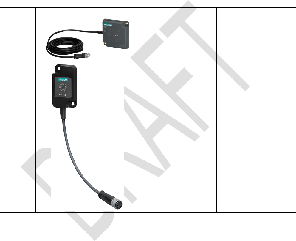
ANT 1
Up to 140 mm 75 x 75 x 20 mm
(L x W x H)
ANT 3
Up to 50 mm 50 x 75 x 10 mm
(L x W x H)
This radio transmitter with IC ID: 267X-RF350R02 has been approved by Industry Canada to operate with the
antenna types listed below with the maximum permissible gain indicated. Antenna types not included in this list,
having a gain greater than the maximum gain indicated for that type, are strictly prohibited for use with this
device.
.
Cet émetteur radio avec IC ID: 267X-RF350R02 a été approuvé par Industrie Canada pour fonctionner avec les
types d'antenne énumérés ci-dessous avec le gain maximal admissible indiqué. types d'antennes non inclus
dans cette liste, ayant un gain supérieur au gain maximum indiqué pour ce type, sont strictement interdits pour
une utilisation avec cet appareil.
For the RF350R and RF350M readers, you can use the following plug-in antennas:
Antennas
6.1 Features
SIMATIC RF300
194 System Manual, 07/2016, C79000-G8976-C345-0x
Antenna
Product photo
Limit distance Sg 1)
Dimensions
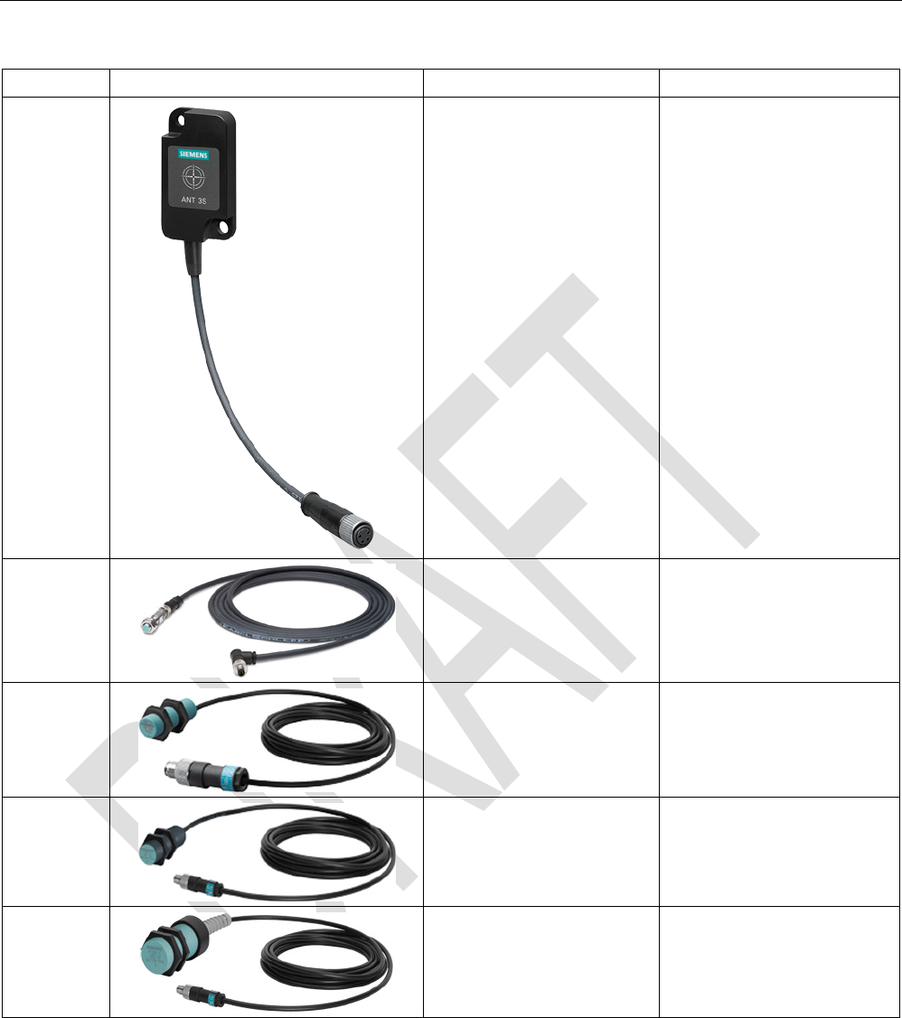
ANT 3S
Up to 5 mm 50 × 28 × 10 mm
(L x W x H)
ANT 8 2)
Up to 4 mm M8 x 1.0 x 39 mm
(∅ x thread x L)
ANT 12
Up to 16 mm M12 x 1.0 x 40 mm
(∅ x thread x L)
ANT 18
Up to 35 mm M18 x 1.0 x 55 mm
(Ø x thread x L)
ANT 30
Up to 55 mm M30 x 1.5 x 61 mm
(Ø x thread x L)
1)
Depending on the transponder used
2) only released with RF350M und RF350R - second generation

Antennas
6.1 Features
SIMATIC RF300
System Manual, 07/2016, C79000-G8976-C345-0x 195
Note
Use of the antennas in hazardous areas
The antennas ANT 1, ANT 12, ANT 18 and ANT 30 are approved for use in hazardous
locations. For more information, refer to the section "
Use of the reader in hazardous areas
(Page
149)".
ANT 1
The ANT 1 is an antenna in the mid performance range and can be used to the customer's
advantage in production and assembly lines due to its manageable housing shape. The
antenna dimensions make it possible to read/write large quantities of data dynamically
from/to the transponder during operation. The antenna cable can be connected at the reader
end.
ANT 3
The ANT 3 is designed for use in small assembly lines. The extremely compact design of the
antenna allows extremely accurate positioning. The antenna cable can be connected at the
reader end.
ANT 3S
The ANT 3S is designed for use in small assembly lines. The extremely compact design of
the antenna allows extremely accurate positioning even with small transponders. The
antenna cable can be connected at the reader end.
ANT 8
The ANT 8 is primarily envisaged for tool identification applications. The extremely small
design of the antenna allows extremely accurate positioning. The antenna cable can be
connected at the reader end and screwed to the antenna.
The antenna ANT 8 has currently only been tested and released for use in conjunction with
the mobile reader RF350M and the reader RF350R - second generation.
ANT 12
The ANT 12 is primarily envisaged for tool identification applications. The very small size of
the antenna means that highly exact positioning is possible using the plastic nuts included in
the scope of delivery. The antenna cable can be connected at the reader end.
ANT 18
The ANT 18 is designed for use in small assembly lines. Due to its small, compact
construction, the antenna can be easily positioned for any application using two plastic nuts
(included in the package). The antenna cable can be connected at the reader end.
Antennas
6.2 Ordering data
SIMATIC RF300
196 System Manual, 07/2016, C79000-G8976-C345-0x
ANT 30
The ANT 30 is designed for use in small assembly lines. In comparison to ANT 18, the
maximum write/read distance is approximately 60 % larger. Due to its compact construction,
the antenna can be easily positioned for any application using two plastic nuts (included in
the package). The antenna cable can be connected at the reader end.
6.2
Ordering data
Table 6- 1 Ordering data for antennas
Article number
ANT 1
incl. integrated antenna cable 3 m
6GT2398-1CB00
ANT 3 without antenna connecting cable 6GT2398-1CD30-0AX0
incl. plug-in antenna cable 3 m
6GT2398-1CD40-0AX0
ANT 3S
without antenna connecting cable
6GT2398-1CD50-0AX0
incl. plug-in antenna cable 3 m
6GT2398-1CD60-0AX0
ANT 8
without antenna connecting cable
6GT2398-1CF00
incl. plug-in antenna cable 3 m
6GT2398-1CF10
ANT 12
incl. plug-in antenna cable 3 m
6GT2398-1CC00
ANT 18
incl. plug-in antenna cable 3 m
6GT2398-1CA00
ANT 30
incl. plug-in antenna cable 3 m
6GT2398-1CD00
Table 6- 2 Antenna accessories ordering data
Article number
Antenna connecting cable
3 m
6GT2398-0AH30
6.3
Ensuring reliable data exchange
The "center point" of the transponder must be situated within the transmission window.
Antennas
6.4 Metal-free area
SIMATIC RF300
System Manual, 07/2016, C79000-G8976-C345-0x 197
6.4
Metal-free area
The antennas ANT 1, ANT 8, ANT 12, ANT 18 and ANT 30 can be flush-mounted in metal.
Please allow for a possible reduction in the field data values. During installation, maintain the
minimum distances (a and b) on/flush with the metal.
Note
Reduction of range if the metal-free space is not maintained
At values lower than a and b, the field data changes significantly, resulting in a reduction in
the limit distance a
nd operating distance. Therefore, during installation, maintain the
minimum distances (a and b) on/flush with the metal.
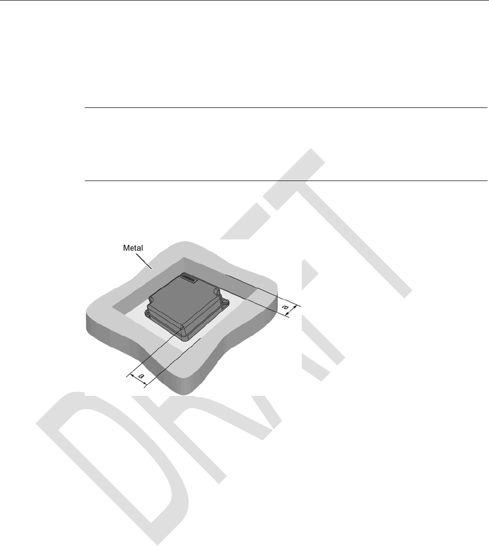
Metal-free space for flush-mounted installation of ANT 1
a =
40 mm
Figure 6-1 ANT 1 flush-mounted in metal
Antennas
6.4 Metal-free area
SIMATIC RF300
198 System Manual, 07/2016, C79000-G8976-C345-0x
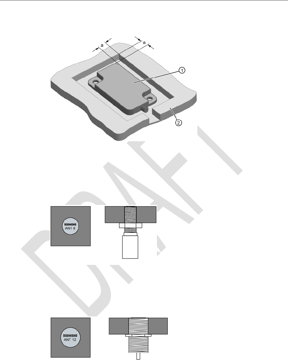
Metal-free space for flush-mounted installation of ANT 3 and ANT 3S
①
ANT 3
②
Metal
a
= 10 mm
Figure 6-2 ANT 3 and ANT 3S flush-mounted in metal
Flush-mounting of ANT 8
Figure 6-3 ANT 8 flush-mounted in metal
The ANT 8 can be flush-mounted in metal.
Flush-mounting of ANT 12
Figure 6-4 ANT 12 flush-mounted in metal
The ANT 12 can be flush-mounted in metal.
Antennas
6.4 Metal-free area
SIMATIC RF300
System Manual, 07/2016, C79000-G8976-C345-0x 199
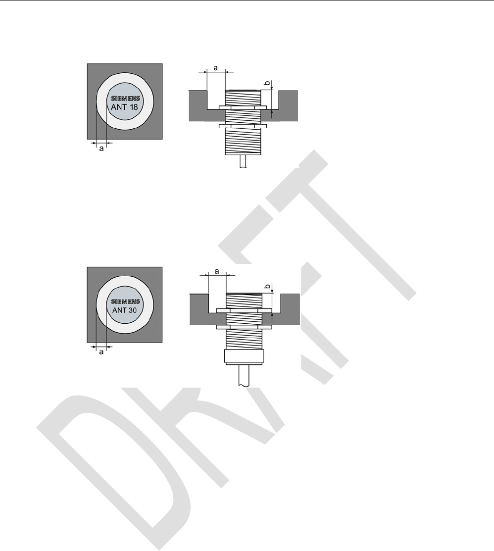
Metal-free space for flush-mounted installation of ANT 18
a =
10 mm
b =
10 mm
Figure 6-5 ANT 18 flush-mounted in metal
Metal-free space for flush-mounted installation of ANT 30
a =
20 mm
b =
20 mm
Figure 6-6 ANT 30 flush-mounted in metal
Antennas
6.5 Minimum distance between antennas
SIMATIC RF300
200 System Manual, 07/2016, C79000-G8976-C345-0x
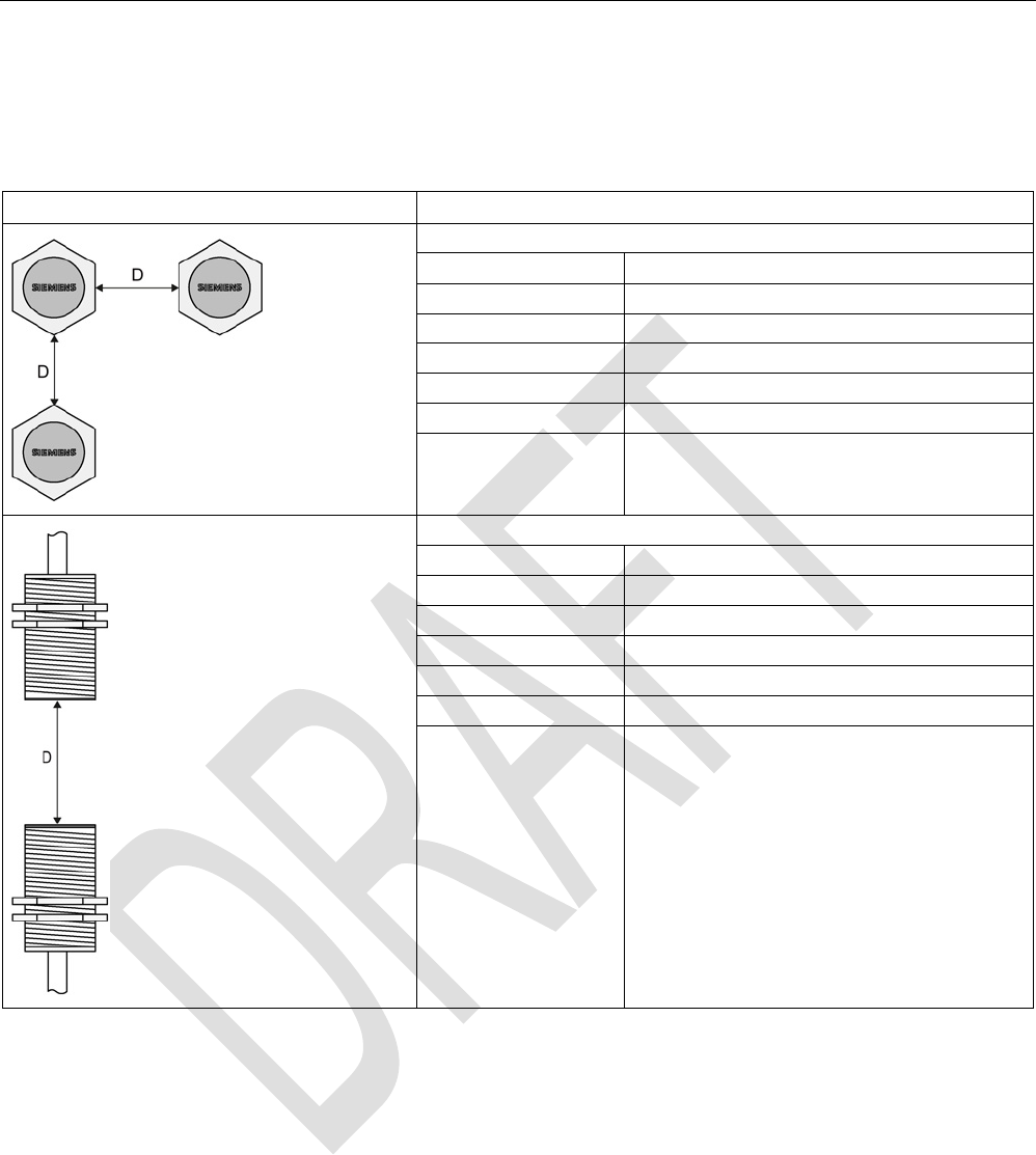
6.5
Minimum distance between antennas
Table 6- 3 Minimum distance between antennas
Diagram (example)
Minimum distance [mm]
Antennas next to each other
ANT 1 D ≥ 100 mm
ANT 3
D ≥ 80 mm
ANT 3S D ≥ 20 mm
ANT 8
D ≥ 50 mm
ANT 12
D ≥ 70 mm
ANT 18
D ≥ 100 mm
ANT 30 D ≥ 100 mm
Antennas face to face
ANT 1
D ≥ 500 mm
ANT 3
D ≥ 100 mm
ANT 3S
D ≥ 50 mm
ANT 8
D ≥ 50 mm
ANT 12
D ≥ 100 mm
ANT 18
D ≥ 100 mm
ANT 30 D ≥ 200 mm
The reader electronics can be mounted directly alongside each other.

Antennas
6.6 Technical specifications
SIMATIC RF300
System Manual, 07/2016, C79000-G8976-C345-0x 201
6.6
Technical specifications
Table 6- 4 Technical specifications of the antennas ANT 1, ANT 3 , ANT 3S and ANT 8
ANT 1
ANT 3
ANT 3S
ANT 8
Max. write/read distance
antenna ↔ transponder (S
g
)
140 mm 50 mm 5 mm 4 mm
Housing dimensions 75 x 75 x 20 mm
(L x W x H)
50 x 28 x 10 mm
(L x W x H)
50 x 28 x 10 mm
(L x W x H)
M8 x 1.0 x 39 mm
(Ø x thread x L)
Color
Anthracite
Black
Black
silver-metallic
Material Plastic
PA 12
Plastic
PA6-V0
Plastic
PA6-V0
Stainless steel
Plug connection M8, 4-pin;
(pins on antenna
side)
M8, 4-pin;
socket on antenna
side
M8, 4-pin;
socket on antenna
side
M8, 4-pin;
(pins on antenna
side)
Degree of protection to EN
60529
IP67 IP67 (front)
Shock-resistant acc. to
EN 60721-3-7, Class 7M2
Vibration-resistant to
EN 60721-3-7, Class 7M2
50 g 1)
20 g (3 to 50 Hz)
1)
Attachment of the antenna 2 x M5 screws 2 x M4 screws 2 x M4 screws 2x stainless steel
nuts
M8 x 1.0 mm
Ambient temperature
• During operation
• During transportation
and storage
• -25 ℃ ... +70 ℃
• -40 °C ... +85 °C
Weight, approx.
• without antenna cable
• with antenna cable
(3.0 m)
• --
• 225 g
• 35 g
• 160 g
• 35 g
• 160 g
• 10 g
• 140 g
1) Warning: The values for shock and vibration are maximum values and must not be applied continuously.

Antennas
6.6 Technical specifications
SIMATIC RF300
202 System Manual, 07/2016, C79000-G8976-C345-0x
Table 6- 5 Technical specifications of the antennas ANT 12, ANT 18 and ANT 30
ANT 12
ANT 18
ANT 30
Max. write/read distance
antenna ↔ transponder (S
g
)
16 mm 35 mm 55 mm
Housing dimensions M12 x 1.0 x 40 mm
(Ø x thread x L)
M18 x 1.0 x 55 mm
(Ø x thread x L)
M30 x 1.5 x 61 mm
(Ø x thread x L)
Color
Pale turquoise
Material Plastic
Crastin
Plug connection M8, 4-pin;
(pins on antenna side)
Degree of protection to EN
60529
IP67 (front)
Shock-resistant acc. to
EN 60721-3-7, Class 7M2
Vibration-resistant to
EN 60721-3-7, Class 7M2
50 g 1)
20 g (3 to 50 Hz)
1)
Attachment of the antenna 2 plastic nuts
M12 x 1.0 mm
2 plastic nuts
M18 x 1.0 mm
2 plastic nuts
M30 x 1.5 mm
Ambient temperature
• During operation
• During transportation
and storage
• -25 ℃ to +70 ℃
• -40 ℃ to +85 ℃
Approx. weight
• without antenna cable
• with antenna cable
(3.0 m)
• --
• 145 g
• --
• 130 g
• --
• 180 g
1) Warning: The values for shock and vibration are maximum values and must not be applied continuously.
Antennas
6.7 Dimensional drawings
SIMATIC RF300
System Manual, 07/2016, C79000-G8976-C345-0x 203
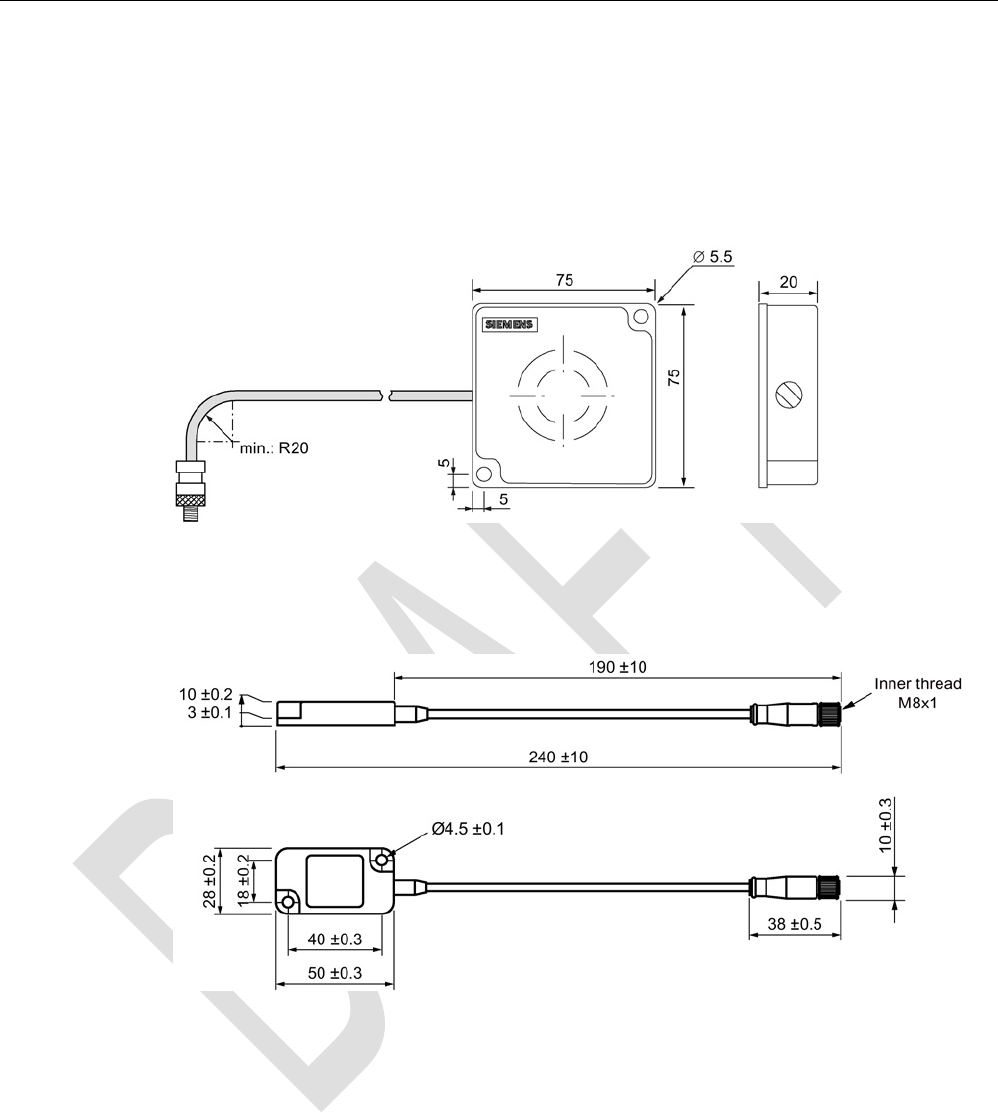
6.7
Dimensional drawings
The cable length is 3 m. All dimensions are in mm.
ANT 1
Figure 6-7 Dimension drawing for ANT 1
ANT 3 / ANT 3S
Figure 6-8 Dimension drawing ANT 3 7 ANT 3S
Antennas
6.7 Dimensional drawings
SIMATIC RF300
204 System Manual, 07/2016, C79000-G8976-C345-0x
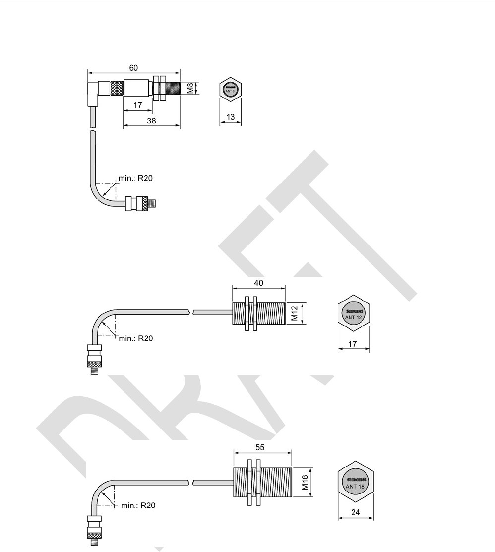
ANT 8
Figure 6-9 Dimension drawing for ANT 8
ANT 12
Figure 6-10 Dimension drawing for ANT 12
ANT 18
Figure 6-11 Dimension drawing for ANT 18
Antennas
6.7 Dimensional drawings
SIMATIC RF300
System Manual, 07/2016, C79000-G8976-C345-0x 205
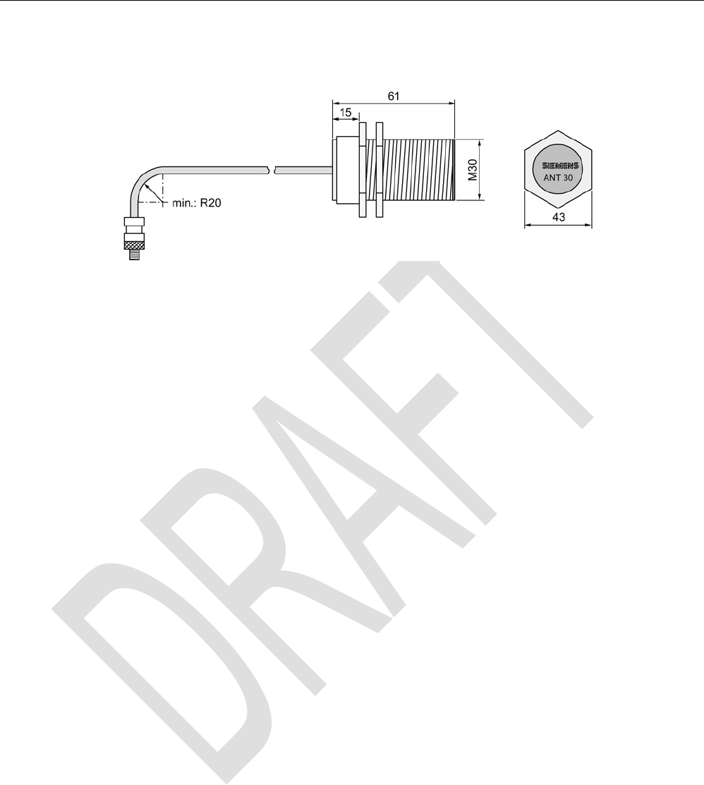
ANT 30
Figure 6-12 Dimension drawing for ANT 30

Antennas
6.7 Dimensional drawings
SIMATIC RF300
206 System Manual, 07/2016, C79000-G8976-C345-0x

SIMATIC RF300
System Manual, 07/2016, C79000-G8976-C345-0x 207
RF300 transponder
7
Features of the RF300 transponders
The RF300 transponders (RF3xxT) stand out particularly for their extremely fast data
exchange with the RF300 readers (RF3xxR). With the exception of the RF320T transponder,
all of the RF300 transponders have 8 to 64 KB of FRAM memory, which has an almost
unlimited capacity for reading and writing.
RF300 transponder
7.1 Memory configuration of the RF300 transponders
SIMATIC RF300
208 System Manual, 07/2016, C79000-G8976-C345-0x
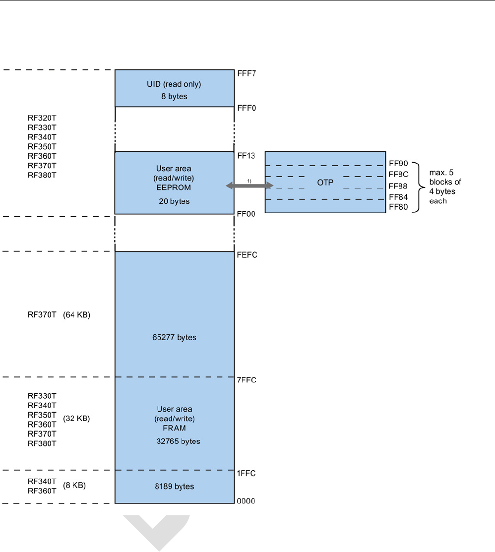
7.1
Memory configuration of the RF300 transponders
1) Physically identical memory When the OTP area is used, the corresponding user area (FF00-FF13) can no longer
be modified (read only).
Figure 7-1 Memory configuration of the RF300 transponders

RF300 transponder
7.1 Memory configuration of the RF300 transponders
SIMATIC RF300
System Manual, 07/2016, C79000-G8976-C345-0x 209
EEPROM area
The memory configuration of an RF300 transponder always comprises an EEPROM that has
20 bytes for user data (read/write) and a 4-byte unique serial number (UID, read only). For
reasons of standardization, the UID is transferred as an 8 byte value through a read
command to address FFF0 with a length of 8. The unused 4 high bytes are filled with zeros.
Note
Write speed
The EEPROM user memory (address FF00
-FF13, or FF80-FF90) requires significantly more
time for writing (approx. 11 ms/byte) than the high
-speed FRAM memory. For time-critical
applications with write functions, it is advisable to use FRAM transpond
ers (e.g. RF330T,
RF340T, RF350T, RF360T, RF370T, RF380T).
FRAM area
Depending on the tag type, high-speed FRAM memory is available. (8 KB, 32 KB, 64 KB).
This area does not exist for the RF320T.
In the case of RF3xxT transponders with FRAM memory, the data carrier initialization
command (INIT) is only effective on this memory area but not on the EEPROM area (FF00-
FF13).
OTP area
The EEPROM memory area (address FF00-FF13) can also be used as a so-called "OTP"
memory (One Time Programmable). The 5 block addresses FF80, FF84, FF88, FF8C and
FF90 are used for this purpose. A write command to this block address with a valid length (4,
8, 12, 16, 20 depending on the block address) protects the written data from subsequent
overwriting.
Note
Seamless use of the OTP area
When the OTP area is used, it must be ensured that the blocks are used starting from Block
0 consecutively.
Examples:
•
3 blocks (with write command), Block 0, 1, 2 (FF80, length = 12): valid
•
2 blocks (consecutive), Block 0 (FF80, length =4), Block 1 (FF84, length = 4): valid
•
2 blocks (consecutive), Block 0 (FF80, length =4), Block 2 (FF88, length = 4): Invalid
•
1 Block, Block 4 (FF90, length = 4): Invalid

RF300 transponder
7.1 Memory configuration of the RF300 transponders
SIMATIC RF300
210 System Manual, 07/2016, C79000-G8976-C345-0x
Note
Use of the OTP area is not reversible
If you use the OPT area, you cannot undo i
t, because the OPT area can only be written to
once.
RF300 transponder
7.2 SIMATIC RF320T
SIMATIC RF300
System Manual, 07/2016, C79000-G8976-C345-0x 211
7.2
SIMATIC RF320T
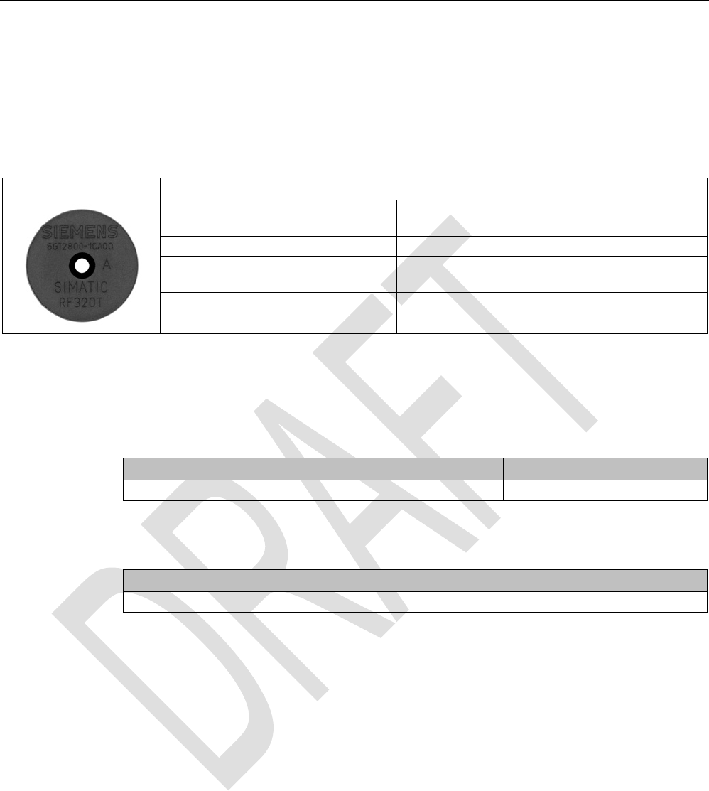
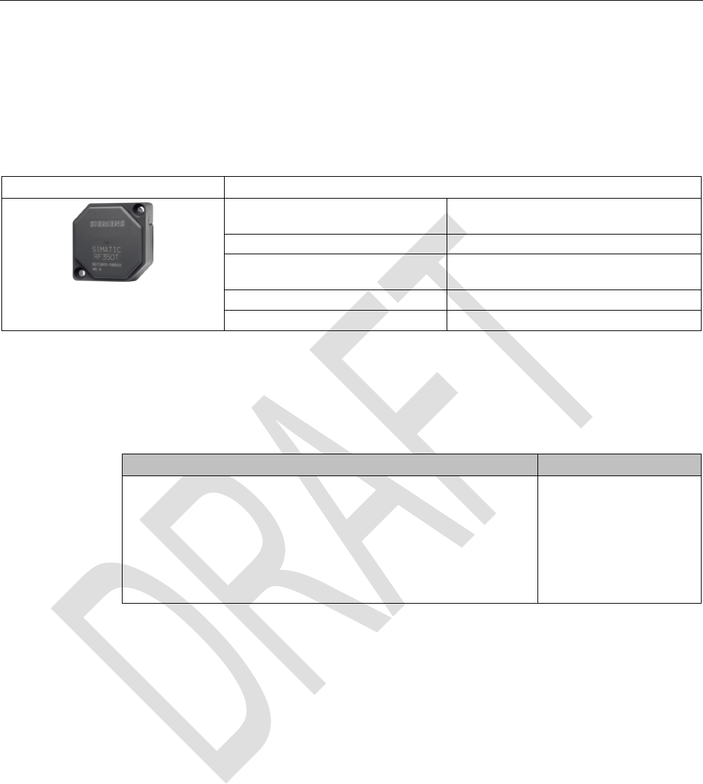
7.2.1
Features
RF320T
Characteristics
Area of application Identification tasks on small assembly lines in harsh
industrial environments
Memory size
20 bytes of EEPROM user memory
Write/read range See section Field data of RF300 transponders
(Page 49)
Mounting on metal
Yes, with spacer
Degree of protection
IP67/IPx9K
7.2.2
Ordering data
Table 7- 1 Ordering data RF320T
Article number
RF320T
6GT2800-1CA00
Table 7- 2 Ordering data for RF320T accessories
Article number
Spacer
6GT2690-0AK00
RF300 transponder
7.2 SIMATIC RF320T
SIMATIC RF300
212 System Manual, 07/2016, C79000-G8976-C345-0x
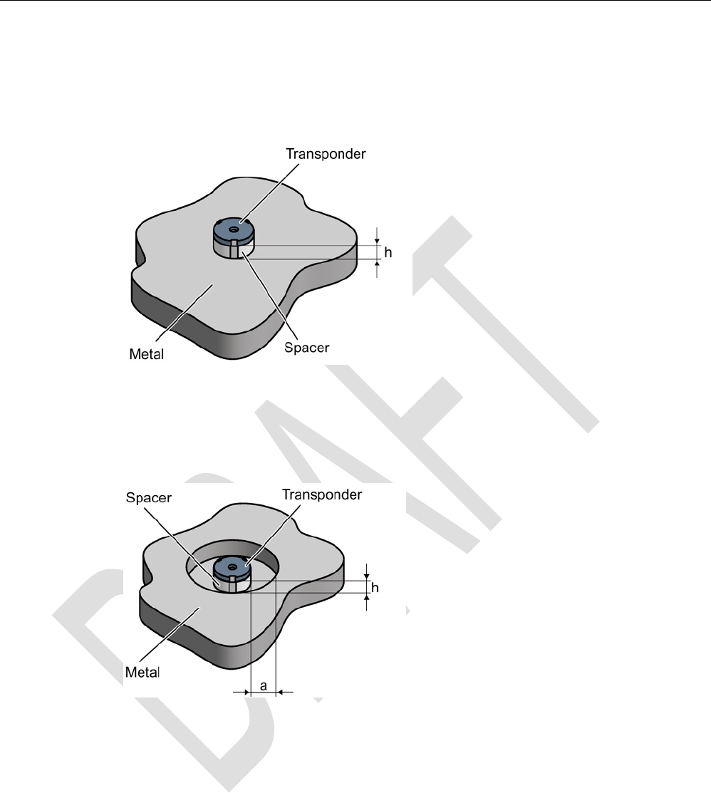
7.2.3
Mounting on metal
Mounting on metal
h
≥ 15 mm
Figure 7-2 Mounting the MDS D124/D324/D424/D524/E624 and RF320T on metal with spacer
Flush-mounting
h
≥ 15 mm
a
≥ 25 mm
Figure 7-3 Flush-mounting of the MDS D124/D324/D424/D524/E624 and RF320T in metal with
spacer

RF300 transponder
7.2 SIMATIC RF320T
SIMATIC RF300
System Manual, 07/2016, C79000-G8976-C345-0x 213
Note
Going below the distances
If the distances (a and h) are not observed, a reduction of the field data results. It is possible
to mount the MDS with metal screws (M3 countersunk head screws). This has no tangible
impact on the range.
7.2.4
Technical data
Table 7- 3 Technical specifications for RF320T
6GT2800-1CA00
Product type designation
SIMATIC RF320T
Memory
Memory organization Byte-oriented, write protection possible in 4-byte
blocks
Memory configuration
• UID • 4 bytes EEPROM
• User memory • 20 bytes EEPROM
• OPT memory • 20 bytes EEPROM
Read cycles (at < 40 ℃)
> 10
14
Write cycles (at < 40 ℃)
> 10
5
Data retention time (at < 40 ℃)
> 10 years
Write/read distance (Sg) Dependent on the reader used, see section "Field
data of RF300 transponders (Page 49)"
MTBF (Mean Time Between Failures)
1800 years
Mechanical specifications
Housing
• Material • Epoxy resin
• Color • Black
Recommended distance to metal
≥ 20 mm
Power supply
Inductive, without battery
RF300 transponder
7.2 SIMATIC RF320T
SIMATIC RF300
214 System Manual, 07/2016, C79000-G8976-C345-0x
6GT2800-1CA00
Permitted ambient conditions
Ambient temperature
• During operation • -25 to +125 ℃
• During transportation and storage • -40 to +140 ℃
Degree of protection to EN 60529 • IP67
• IPx9K
Shock-resistant to EN 60721-3-7, Class 7 M3
100 g
1)
Vibration-resistant to EN 60721-3-7, Class 7 M3
20 g
1)
Torsion and bending load
Not permitted
Design, dimensions and weight
Dimensions (Ø x H)
27 x 4 mm
Weight
5 g
Type of mounting • 1 x M3 screw 2)
≤ 1.0 Nm
• Glued
1)
The values for shock and vibration are maximum values and must not be applied continuously.
2 ) To prevent it loosening during operation, secure the screw with screw locking varnish.
7.2.5
Dimension drawing
Figure 7-4 RF320T dimension drawing
Dimensions in mm
RF300 transponder
7.3 SIMATIC RF330T
SIMATIC RF300
System Manual, 07/2016, C79000-G8976-C345-0x 215
7.3
SIMATIC RF330T
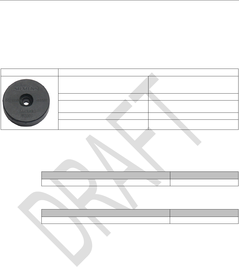
7.3.1
Features
Table 7- 4
RF330T
Characteristics
Area of application In production automation for identification of
metallic workpiece holders, workpieces or
containers.
Memory size 32 KB EEPROM user memory
Write/read range See section "Field data of RF300 transpond-
ers (Page 49)"
Mounting on metal
Yes flush mounted on/in metal
Degree of protection IP68/IPx9K
7.3.2
Ordering data
Table 7- 5 Ordering data RF330T
Article number
RF330T
6GT2800-5BA00
Table 7- 6 Ordering data for RF330T accessories
Article number
Fixing hood RF330T / MDS D423
6GT2690-0EA00
RF300 transponder
7.3 SIMATIC RF330T
SIMATIC RF300
216 System Manual, 07/2016, C79000-G8976-C345-0x
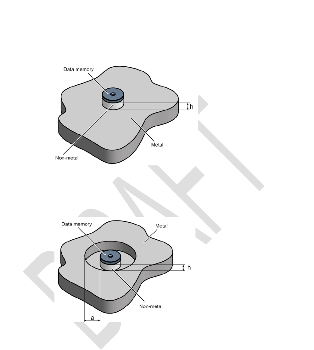
7.3.3
Mounting on/in metal
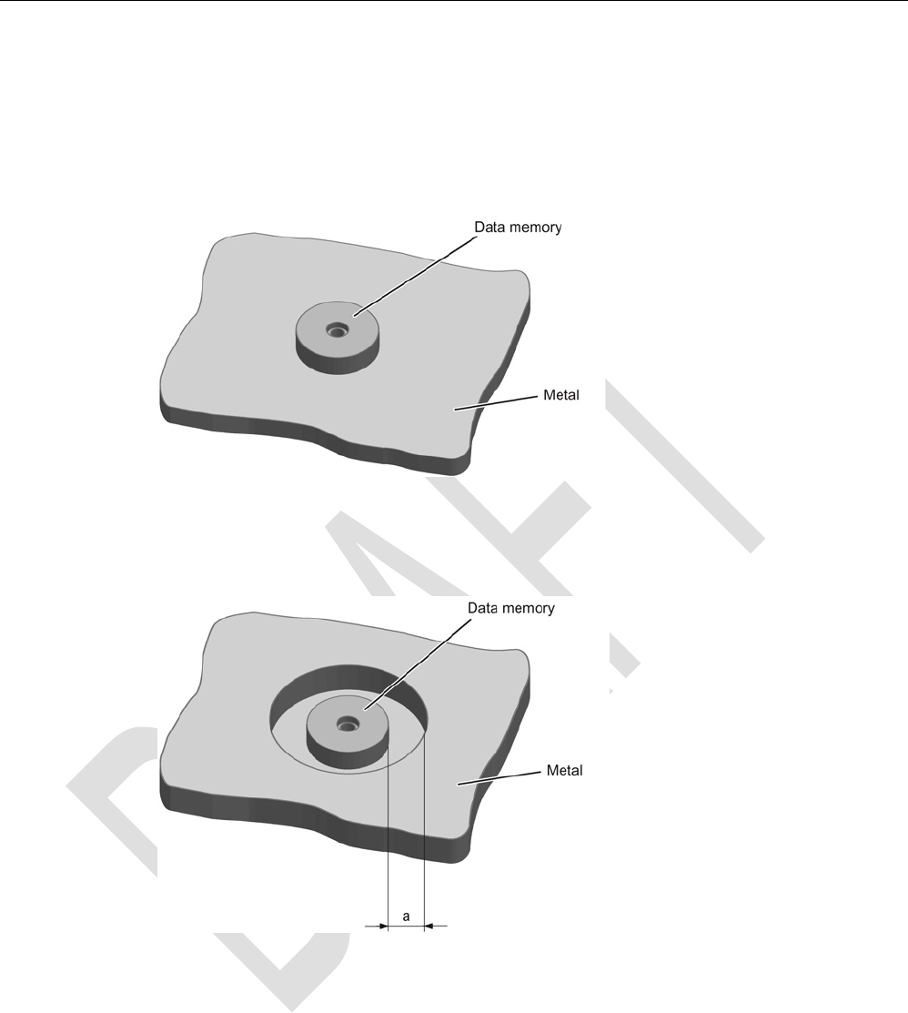
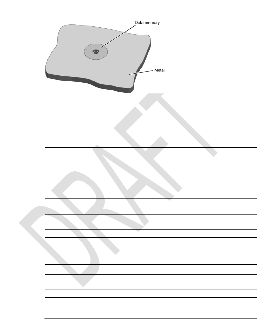
Direct mounting of the RF330T on metal is permitted.
Mounting of the RF330T on metal
Figure 7-5 Mounting of the RF330T on metal
Flush-mounting of RF330T in metal
a
≥ 10 mm
Figure 7-6 Mounting of the RF330T in metal with 10 mm clearance
RF300 transponder
7.3 SIMATIC RF330T
SIMATIC RF300
System Manual, 07/2016, C79000-G8976-C345-0x 217
Figure 7-7 Mounting of the RF330T in metal without clearance
Note
Reduction of the write/read range
Note that when the device is flush
-mounted in metal without a surrounding clearance ≥ 10
mm, the write/read range is significantly reduced.
7.3.4
Technical specifications
Table 7- 7 RF330T technical specifications
6GT2800-5BA00
Product type designation
SIMATIC RF330T
Memory
Memory organization in bytes
Memory configuration
• UID • 4 bytes EEPROM
• User memory • 8 KB FRAM
• OPT memory • 20 bytes EEPROM
Read cycles (at < 40 ℃)
> 10
14
Write cycles (at < 40 ℃) > 1014
Data retention time (at < 40 ℃)
> 10 years
Write/read distance (Sg) Dependent on the reader used, see section "Field
data of RF300 transponders (Page 49)"
MTBF (Mean Time Between Failures)
1200 years

RF300 transponder
7.3 SIMATIC RF330T
SIMATIC RF300
218 System Manual, 07/2016, C79000-G8976-C345-0x
6GT2800-5BA00
Mechanical specifications
Housing
• Material • Plastic PPS
• Color • Black
Recommended distance to metal
≥ 0 mm
Power supply
Inductive, without battery
Permitted ambient conditions
Ambient temperature
• During operation • -25 to +85 ℃
• During transportation and storage • -40 to +100 ℃
Degree of protection to EN 60529 • IP68
2 hours, 2 m, 20 ℃
• IPx9K
steam jet: 150 mm; 10 to 15 l/min; 100 bar; 75
°C
Pressure resistance • Low pressure resistant
vacuum dryer: up to 20 mbar
• high pressure resistant (see degree of protec-
tion IPx9K)
Shock-resistant to EN 60721-3-7, Class 7 M3
50 g
1)
Vibration-resistant to EN 60721-3-7, Class 7 M3
20 g
1)
Torsion and bending load
Not permitted
Design, dimensions and weight
Dimensions (Ø x H)
30 x 8 mm
Weight
10 g
Type of mounting 1 x M4 screw 2)
≤ 1.5 Nm
1)
The values for shock and vibration are maximum values and must not be applied continuously.
2 ) To prevent it loosening during operation, secure the screw with screw locking varnish.
RF300 transponder
7.3 SIMATIC RF330T
SIMATIC RF300
System Manual, 07/2016, C79000-G8976-C345-0x 219
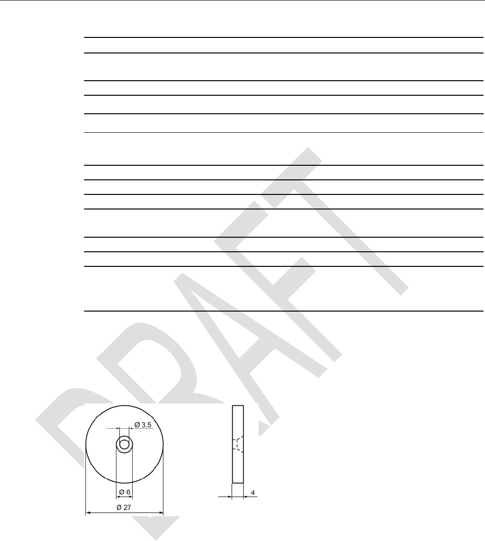
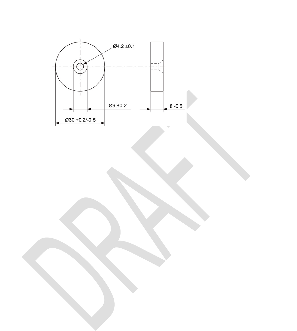
7.3.5
Dimension drawing
Figure 7-8 RF330T dimension drawing
Dimensions in mm
RF300 transponder
7.4 SIMATIC RF340T
SIMATIC RF300
220 System Manual, 07/2016, C79000-G8976-C345-0x
7.4
SIMATIC RF340T
7.4.1
Features
Table 7- 8
RF340T
Characteristics
Area of application Identification tasks on small assembly lines
in harsh industrial environments
Memory size • 8 KB FRAM user memory
• 32 KB FRAM user memory
Write/read range See section Field data of RF300 tran-
sponders (Page 49)
Mounting on metal
Yes
Degree of protection IP68/IPx9K
7.4.2
Ordering data
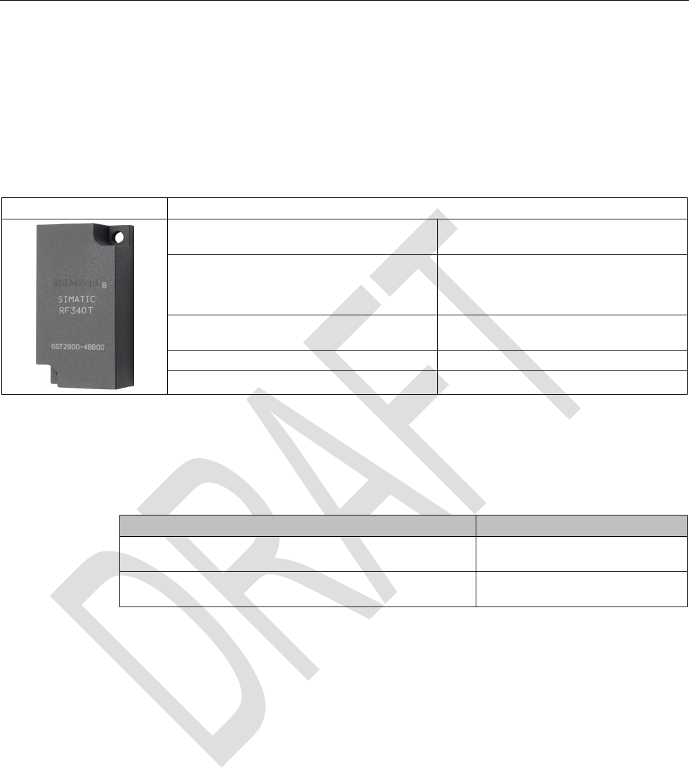
Table 7- 9 Ordering data RF340T
Article number
RF340T
8 KB FRAM user memory
6GT2800-4BB00
RF340T
32 KB FRAM user memory
6GT2800-5BB00
RF300 transponder
7.4 SIMATIC RF340T
SIMATIC RF300
System Manual, 07/2016, C79000-G8976-C345-0x 221
7.4.3
Mounting on metal
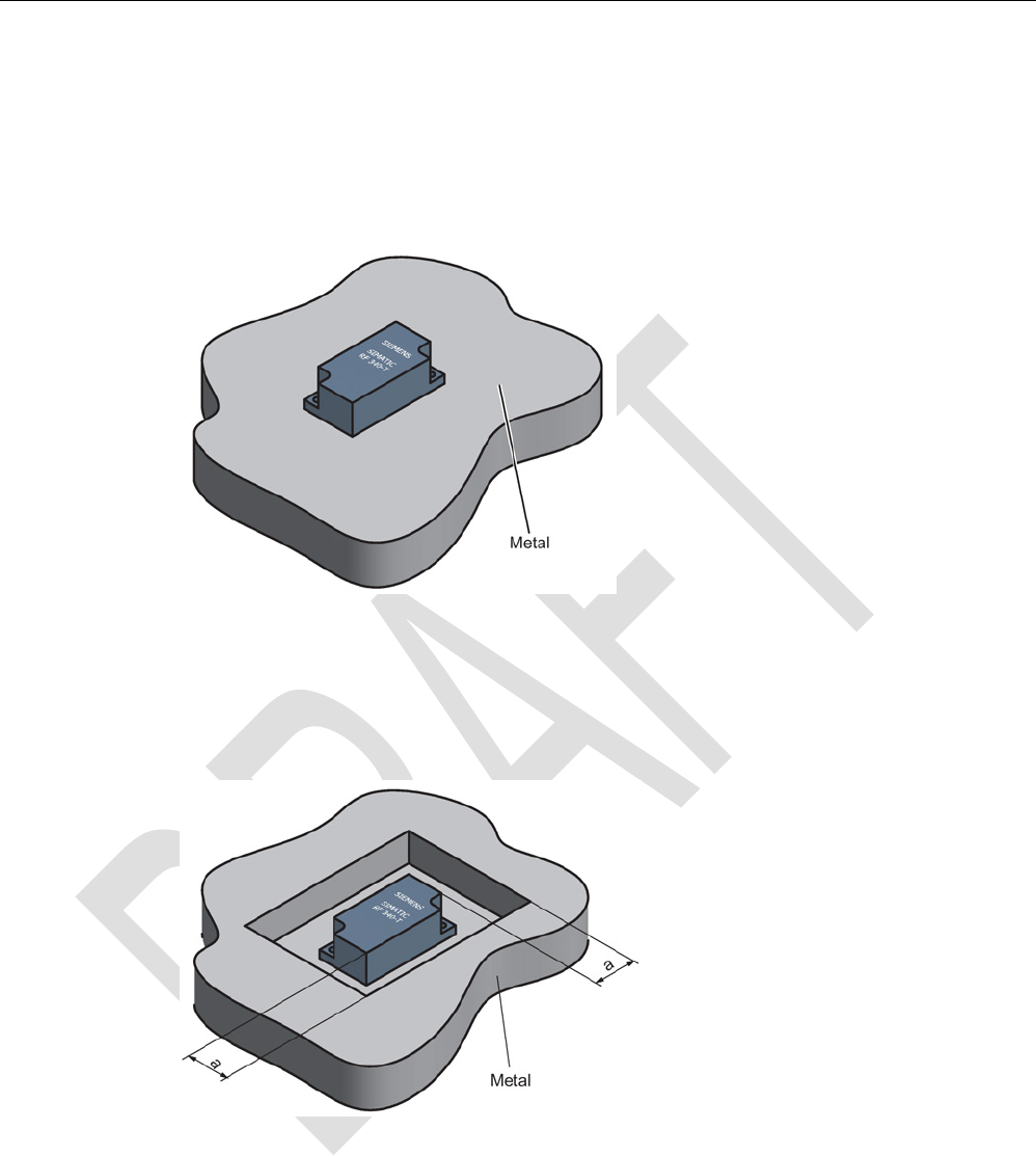
Direct mounting of the RF340T on metal is permitted.
Mounting of RF340T on metal
Figure 7-9 Mounting of RF340T on metal
Flush-mounting of RF340T in metal:
Figure 7-10 Flush-mounting of RF340T in metal
The standard value for a is ≥ 20 mm. At lower values, the field data change significantly,
resulting in a reduction in the range.

RF300 transponder
7.4 SIMATIC RF340T
SIMATIC RF300
222 System Manual, 07/2016, C79000-G8976-C345-0x
7.4.4
Technical specifications
Table 7- 10 Technical specifications for RF340T
6GT2800-4BB00
Product type designation
SIMATIC RF340T
Memory
Memory organization
in bytes
Memory configuration
• UID • 4 bytes EEPROM
• User memory • 8 KB FRAM
• OPT memory • 20 bytes EEPROM
Read cycles (at < 40 ℃)
> 10
10
Write cycles (at < 40 ℃)
> 10
10
Data retention time (at < 40 ℃)
> 10 years
Write/read distance (Sg) Dependent on the reader used, see section "Field
data of RF300 transponders (Page 49)"
MTBF (Mean Time Between Failures)
1200 years
Mechanical specifications
Housing
• Material • Plastic PA 12
• Color • Anthracite
Recommended distance to metal
≥ 0 mm
Power supply
Inductive, without battery
Permitted ambient conditions
Ambient temperature
• During operation • -25 to +85 ℃
• During transportation and storage • -40 to +85 ℃
Degree of protection to EN 60529 • IP68
• IPx9K
Shock-resistant to EN 60721-3-7, Class 7 M3
50 g
1)
Vibration-resistant to EN 60721-3-7, Class 7 M3 20 g 1)
Torsion and bending load Not permitted
RF300 transponder
7.4 SIMATIC RF340T
SIMATIC RF300
System Manual, 07/2016, C79000-G8976-C345-0x 223
6GT2800-4BB00
Design, dimensions and weight
Dimensions (L x W x H)
48 x 25 x 15 mm
Weight
25 g
Type of mounting 2 x M3 screws
≤ 1.0 Nm
1) The values for shock and vibration are maximum values and must not be applied continuously.
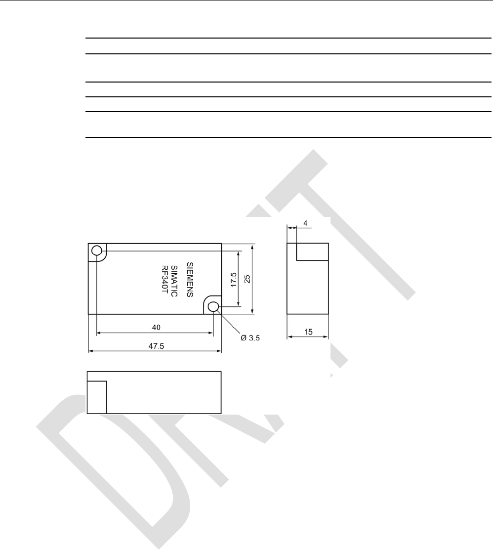
7.4.5
Dimension drawing
Figure 7-11 RF340T dimension drawing
Dimensions in mm
RF300 transponder
7.5 SIMATIC RF350T
SIMATIC RF300
224 System Manual, 07/2016, C79000-G8976-C345-0x
7.5
SIMATIC RF350T
7.5.1
Features
RF350T
Characteristics
Area of application Identification tasks on small assembly lines
in harsh industrial environments
Memory size
32 KB FRAM user memory
Write/read range See section Field data of RF300 tran-
sponders (Page 49)
Mounting on metal
Yes
Degree of protection
IP68
7.5.2
Ordering data
Table 7- 11 Ordering data RF350T
Article number
• IP68
• Memory size: 32 KB FRAM (read/write) and 4 bytes EEPROM (read
only)
• Operating temperature: -25 °C to +85 °C
• Dimensions: 50 x 50 x 20 (L x W x H, in mm)
• incl. securing frame
6GT2800-5BD00
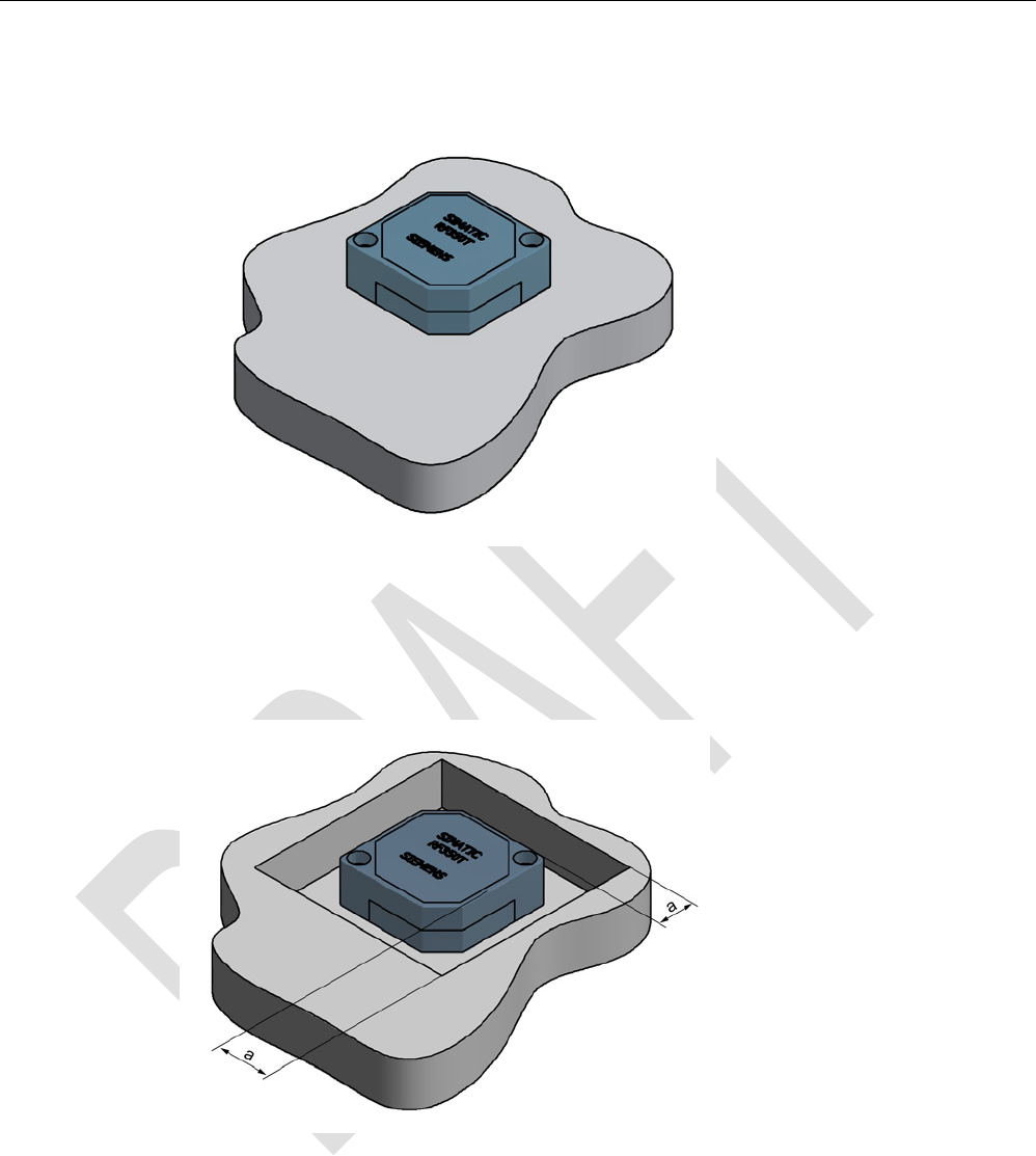
7.5.3
Mounting on metal
Direct mounting of the RF350T on metal is permitted.
RF300 transponder
7.5 SIMATIC RF350T
SIMATIC RF300
System Manual, 07/2016, C79000-G8976-C345-0x 225
Mounting of RF350T on metal
Figure 7-12 Mounting of RF350T on metal
Flush-mounting of RF350T in metal:
Figure 7-13 RF350T flush-mounted in metal
The standard value for a is ≥ 20 mm. At lower values, the field data change significantly,
resulting in a reduction in the range.
RF300 transponder
7.5 SIMATIC RF350T
SIMATIC RF300
226 System Manual, 07/2016, C79000-G8976-C345-0x
7.5.4
Mounting options
Mounting with fixing frame
The RF350T transponder can be mounted as shown with the fixing frame:
Figure 7-14 Installation diagram
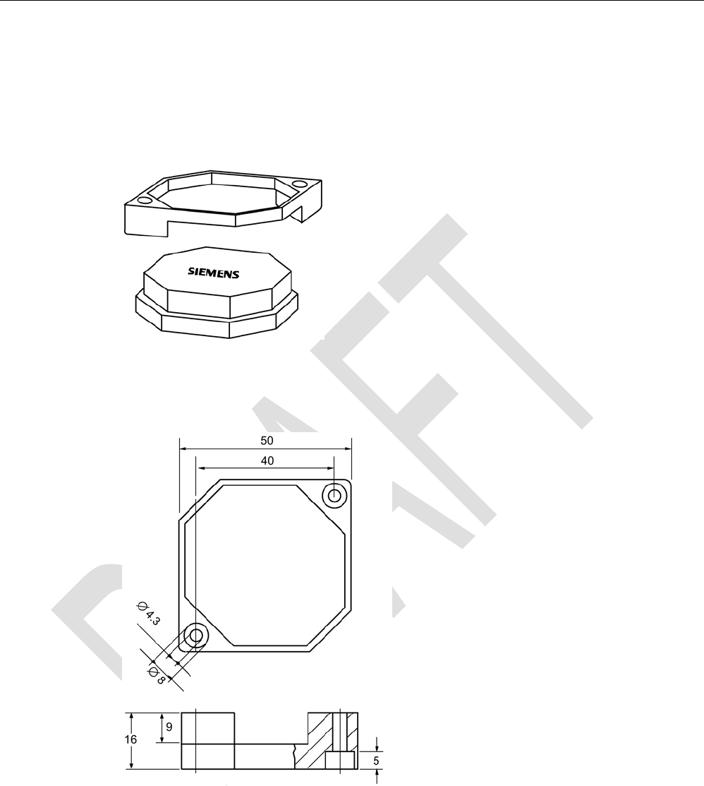
Dimensions of the fixing frame
Figure 7-15 RF350T fixing frame

RF300 transponder
7.5 SIMATIC RF350T
SIMATIC RF300
System Manual, 07/2016, C79000-G8976-C345-0x 227
7.5.5
Technical data
Table 7- 12 Technical specifications for RF350T
6GT2800-5BD00
Product type designation
SIMATIC RF350T
Memory
Memory organization
in bytes
Memory configuration
• UID • 4 bytes EEPROM
• User memory • 32 KB FRAM
• OPT memory • 20 bytes EEPROM
Read cycles (at < 40 ℃)
> 10
10
Write cycles (at < 40 ℃)
> 10
10
Data retention time (at < 40 ℃)
> 10 years
Write/read distance (Sg) Dependent on the reader used, see section "Field
data of RF300 transponders (Page 49)"
MTBF (Mean Time Between Failures)
1200 years
Mechanical specifications
Housing
• Material • Plastic PA 12
• Color • Anthracite
Recommended distance to metal
≥ 0 mm
Power supply
Inductive, without battery
Permitted ambient conditions
Ambient temperature
• During operation • -25 to +85 ℃
• During transportation and storage • -40 to +85 ℃
Degree of protection to EN 60529
IP68
Shock-resistant to EN 60721-3-7, Class 7 M3
50 g
1)
Vibration-resistant to EN 60721-3-7, Class 7 M3
20 g
1)
Torsion and bending load
Not permitted
RF300 transponder
7.5 SIMATIC RF350T
SIMATIC RF300
228 System Manual, 07/2016, C79000-G8976-C345-0x
6GT2800-5BD00
Design, dimensions and weight
Dimensions (L x W x H)
50 x 50 x 20 mm
Weight
25 g
Type of mounting 2 x M4 screws
≤ 1.5 Nm
1) The values for shock and vibration are maximum values and must not be applied continuously.
7.5.6
Dimension drawing
Figure 7-16 RF350T dimension drawing
Dimensions in mm
RF300 transponder
7.6 SIMATIC RF360T
SIMATIC RF300
System Manual, 07/2016, C79000-G8976-C345-0x 229
7.6
SIMATIC RF360T
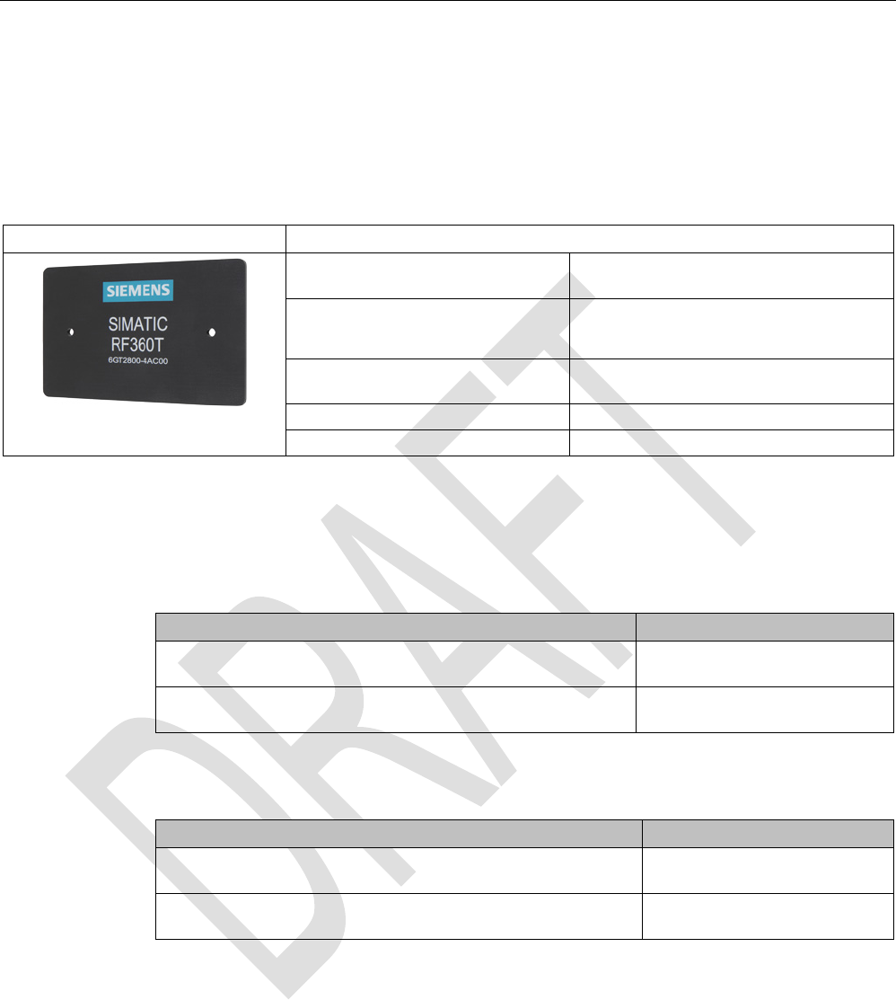
7.6.1
Features
RF360T
Characteristics
Area of application Identification tasks on small assembly lines
in harsh industrial environments
Memory size • 8 KB FRAM user memory
• 32 KB FRAM user memory
Write/read range see section Field data of RF300 tran-
sponders (Page 49)
Mounting on metal Yes, with spacer
Degree of protection
IP67
7.6.2
Ordering data
Table 7- 13 Ordering data RF360T
Article number
RF360T
8 KB FRAM user memory
6GT2800-4AC00
RF360T
32 KB FRAM user memory
6GT2800-5AC00
Table 7- 14 Ordering data for RF360T accessories
Article number
Spacer
(in conjunction with fixing pocket 6GT2190-0AB00)
6GT2190-0AA00
Fixing pocket
(in conjunction with spacer 6GT2190-0AA00)
6GT2190-0AB00
7.6.3
Mounting on metal
Direct mounting of the RF360T on metal is not allowed. A distance ≥ 20 mm is
recommended. This can be achieved using the spacer 6GT2190-0AA00 in combination with
the fixing pocket 6GT2190-0AB00.
RF300 transponder
7.6 SIMATIC RF360T
SIMATIC RF300
230 System Manual, 07/2016, C79000-G8976-C345-0x
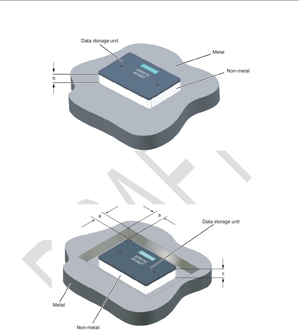
Mounting of RF360T on metal
Figure 7-17 Mounting of RF360T with spacer
The standard value for h is ≥ 20 mm.
Flush-mounting of RF360T in metal:
Figure 7-18 Flush-mounting of RF360T with spacer
The standard value for a is ≥ 20 mm. At lower values, the field data change significantly,
resulting in a reduction in the range.
RF300 transponder
7.6 SIMATIC RF360T
SIMATIC RF300
System Manual, 07/2016, C79000-G8976-C345-0x 231
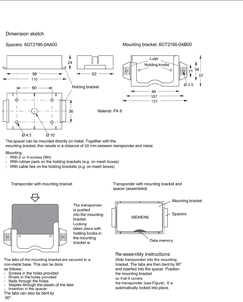
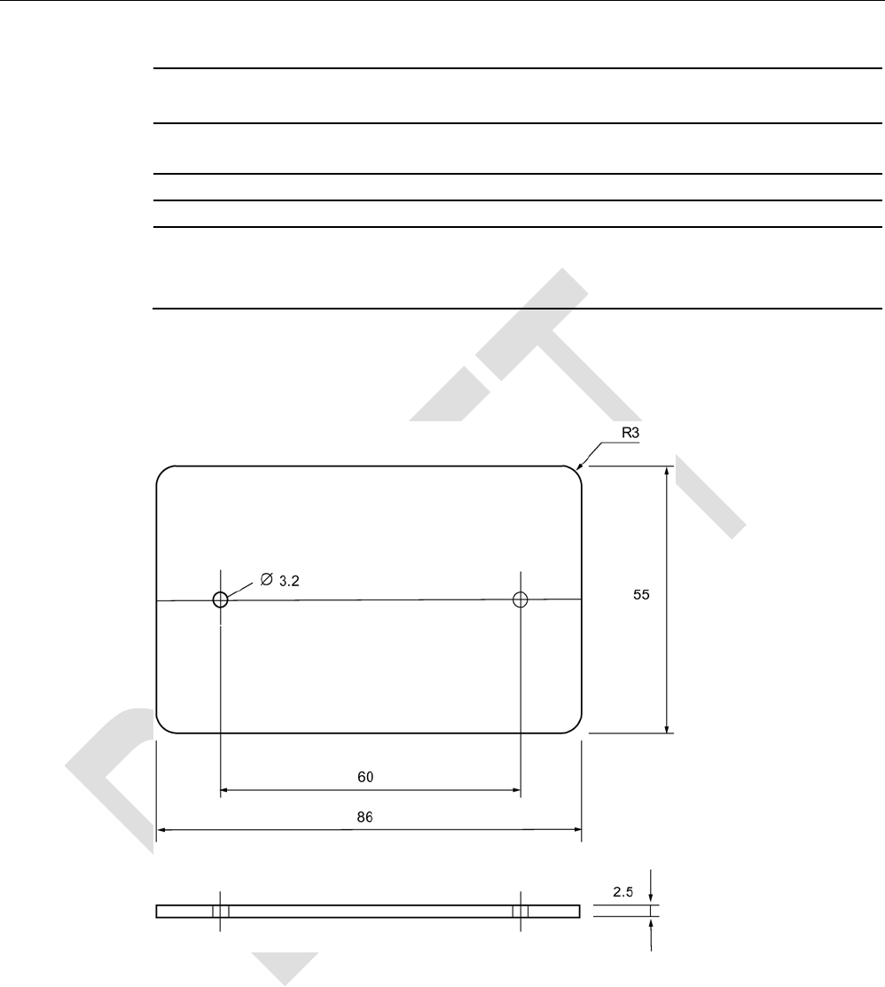
Dimensions of spacer and fixing pocket for RF360T
Figure 7-19 Dimensions of spacer and fixing pocket for RF360T

RF300 transponder
7.6 SIMATIC RF360T
SIMATIC RF300
232 System Manual, 07/2016, C79000-G8976-C345-0x
7.6.4
Technical data
Table 7- 15 Technical specifications for RF360T
6GT2800-4AC00
6GT2800-5AC00
Product type designation
SIMATIC RF360T
Memory
Memory organization
in bytes
Memory configuration
• UID • 4 bytes EEPROM
• User memory • 8 KB FRAM
• OPT memory • 20 bytes EEPROM
Read cycles (at < 40 ℃)
> 10
10
Write cycles (at < 40 ℃)
> 10
10
Data retention time (at < 40 ℃)
> 10 years
Write/read distance (Sg) Dependent on the reader used, see section "Field
data of RF300 transponders (Page 49)"
MTBF (Mean Time Between Failures)
1200 years
Mechanical specifications
Housing
• Material • Epoxy resin
• Color • Anthracite
Recommended distance to metal
≥ 20 mm
Power supply
Inductive, without battery
Permitted ambient conditions
Ambient temperature
• During operation • -25 to +75 ℃
• During transportation and storage • -40 to +85 ℃
Degree of protection to EN 60529
IP67
Shock-resistant to EN 60721-3-7, Class 7 M3
50 g
Vibration-resistant to EN 60721-3-7, Class 7 M3
20 g
Torsion and bending load
Not permitted
RF300 transponder
7.6 SIMATIC RF360T
SIMATIC RF300
System Manual, 07/2016, C79000-G8976-C345-0x 233
6GT2800-4AC00
6GT2800-5AC00
Design, dimensions and weight
Dimensions (L x W x H)
86 x 55 x 2.5 mm
Weight
25 g
Type of mounting • 2 x M3 screws
≤ 1.0 Nm
• Fixing pocket (6GT2190-0AB00)
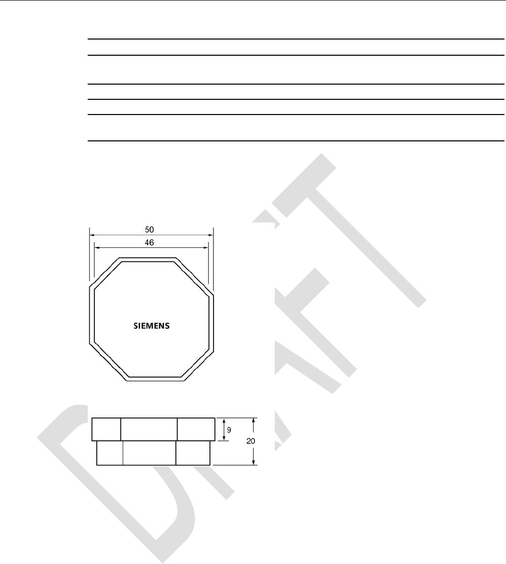
7.6.5
Dimension drawing
Figure 7-20 RF360T dimension drawing
Dimensions in mm
RF300 transponder
7.7 SIMATIC RF370T
SIMATIC RF300
234 System Manual, 07/2016, C79000-G8976-C345-0x
7.7
SIMATIC RF370T
7.7.1
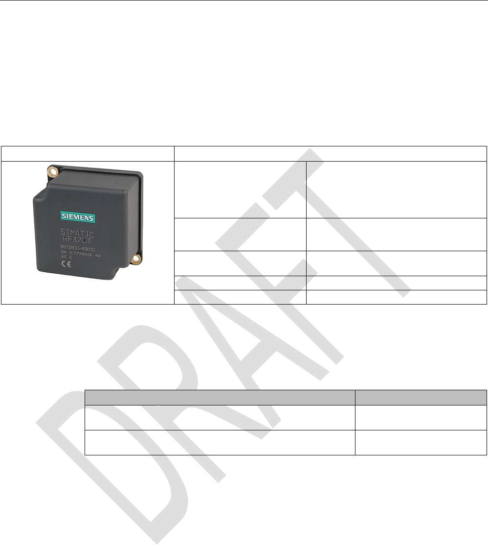
Features
The SIMATIC RF370T transponder is a passive (i.e. battery-free) data carrier in a square
type of construction.
RF370T
Characteristics
Area of application Identification tasks on assembly lines in
harsh industrial environments, due to high
resistance to oils, lubricants and cleaning
agents, and suitable for larger ranges, e.g.
automotive industry
Memory size • 32 KB FRAM user memory
• 64 KB FRAM user memory
Write/read range see section Field data of RF300 transpond-
ers (Page 49)
Mounting on metal
Yes
Degree of protection
IP68/IPx9K
7.7.2
Ordering data
Table 7- 16 Ordering data RF370T
Article number
RF370T
32 KB FRAM user memory
6GT2800-5BE00
RF370T
76 KB FRAM user memory
6GT2800-6BE00
RF300 transponder
7.7 SIMATIC RF370T
SIMATIC RF300
System Manual, 07/2016, C79000-G8976-C345-0x 235
7.7.3
Mounting on metal
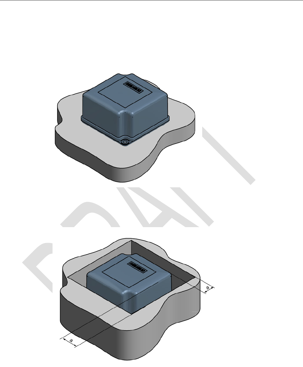
Direct mounting of the RF370T on metal is permitted.
Mounting of RF370T on metal
Figure 7-21 Mounting of RF370T on metal
Flush-mounting of RF370T in metal:
Figure 7-22 RF370T flush-mounted in metal
The standard value for a is ≥ 20 mm. At lower values, the field data change significantly,
resulting in a reduction in the range.

RF300 transponder
7.7 SIMATIC RF370T
SIMATIC RF300
236 System Manual, 07/2016, C79000-G8976-C345-0x
7.7.4
Mounting instructions
It is essential that you observe the instructions in the Section Installation guidelines
(Page 62).
Properties
Description
Type of installation
Screw fixing (two M5 screws)
Tightening torque < 1.2 Nm (at room temperature)
7.7.5
Technical specifications
Table 7- 17 Technical specifications RF370T
6GT2800-5BE00
6GT2800-6BE00
Product type designation
SIMATIC RF370T
Memory
Memory organization
in bytes
Memory configuration
• UID • 4 bytes EEPROM
• User memory • 32 or 64 KB FRAM
• OPT memory • 20 bytes EEPROM
Read cycles (at < 40 ℃)
> 10
10
Write cycles (at < 40 ℃)
> 10
10
Data retention time (at < 40 ℃)
> 10 years
Write/read distance (Sg) Dependent on the reader used, see section "Field
data of RF300 transponders (Page 49)"
MTBF (Mean Time Between Failures)
1200 years
Mechanical specifications
Housing
• Material • Plastic PA 12
• Color • Anthracite
Recommended distance to metal
≥ 0 mm
Power supply
Inductive, without battery
RF300 transponder
7.7 SIMATIC RF370T
SIMATIC RF300
System Manual, 07/2016, C79000-G8976-C345-0x 237
6GT2800-5BE00
6GT2800-6BE00
Permitted ambient conditions
Ambient temperature
• During operation • -25 to +85 ℃
• During transportation and storage • -40 to +85 ℃
Degree of protection to EN 60529
IPx9K
Shock-resistant to EN 60721-3-7, Class 7 M3
50 g
1)
Vibration-resistant to EN 60721-3-7, Class 7 M3
20 g
1)
Torsion and bending load
Not permitted
Design, dimensions and weight
Dimensions (L x W x H)
75 x 75 x 41 mm
Weight
200 g
Type of mounting 2 x M5 screws
≤ 1.5 Nm
1) The values for shock and vibration are maximum values and must not be applied continuously.
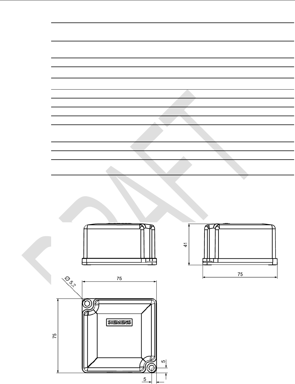
7.7.6
Dimensional drawing
Figure 7-23 RF370T dimension drawing
RF300 transponder
7.8 SIMATIC RF380T
SIMATIC RF300
238 System Manual, 07/2016, C79000-G8976-C345-0x
Dimensions in mm
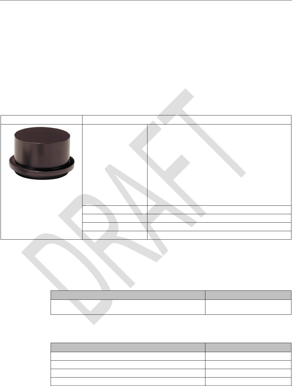
7.8
SIMATIC RF380T
7.8.1
Features
The SIMATIC RF380T transponder is an extremely rugged and heat-resistant round data
carrier suitable e.g. for applications in the automotive industry.
SIMATIC RF380T transponder
Characteristics
Area of application
Identification tasks in applications (e.g. automotive industry)
with cyclic high temperature stress > 85 °C and < 220 °C
Highly resistant to mineral oils, lubricants and cleaning
agents
Typical applications:
• Primer coat, electrolytic dip area, cataphoresis with the
associated drying furnaces
• Top coat area with drying furnaces
• Washing areas at temperatures > 85°C
• Other applications with higher temperatures
Memory size
32 KB FRAM user memory
Write/read range
see section "Field data of RF300 transponders (Page 49)"
Mounting on metal
Yes, flush-mounted in metal
Degree of protection
IP68
7.8.2
Ordering data
Table 7- 18 Ordering data RF380T
Article number
RF380T
User memory 32 KB FRAM (read/write) and 4 bytes EEPROM
6GT2800-5DA00
Table 7- 19 Ordering data for RF380T
Article number
Holder (short version)
6GT2090-0QA00
Holder (long version)
6GT2090-0QA00-0AX3
Shrouding cover
6GT2090-0QB00
Universal holder
6GT2590-0QA00
RF300 transponder
7.8 SIMATIC RF380T
SIMATIC RF300
System Manual, 07/2016, C79000-G8976-C345-0x 239
7.8.3
Installation guidelines for RF380T
It is essential that you observe the instructions in the Section Installation guidelines
(Page 62)
.
The following section only deals with features specific to the SIMATIC RF380T.
7.8.3.1
Mounting instructions
Note
Only use tag with original holder
You are strongly recommended to only use the tag with the original holder specified. Only
this holder guarantees that the data memory observes the listed values for shock, vib
ration
and temperature. A protective cover is recommendable for applications in paint shops.
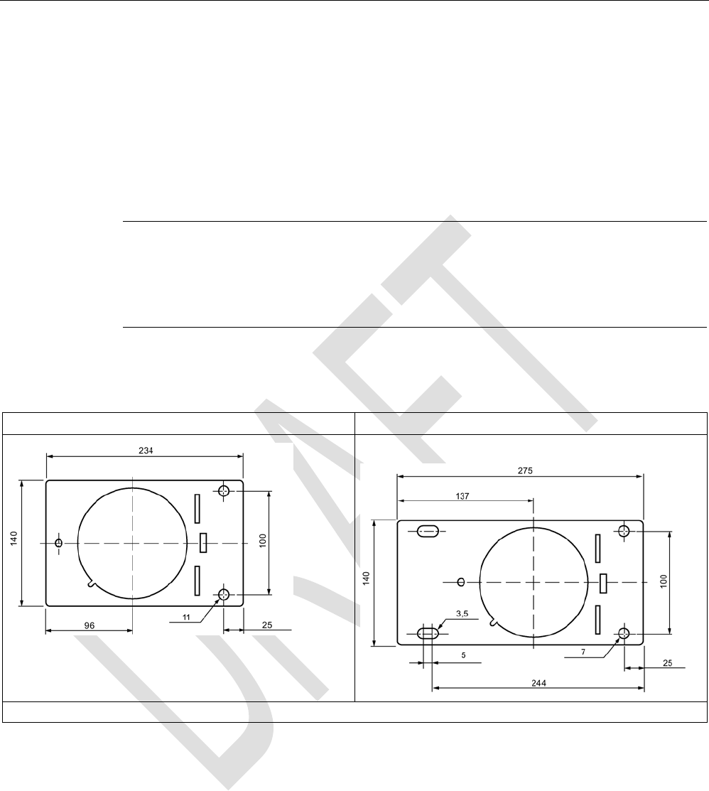
Data memory holder
Short version (6GT2 090-0QA00)
Long version (6GT2090-0QA00-0AX3)
Material: V2A sheet-steel with thickness 2.5 mm BI 2.5 DIN 59382 1.4541
RF300 transponder
7.8 SIMATIC RF380T
SIMATIC RF300
240 System Manual, 07/2016, C79000-G8976-C345-0x
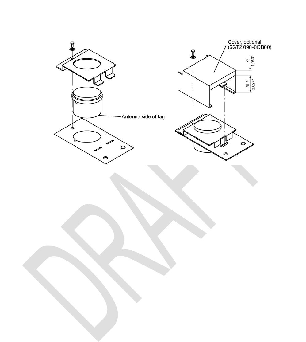
Assembly of data memory with holder
Figure 7-24 Assembly of tag with holder
Scope of supply
The holder is provided with all mounting parts and a mounting diagram. Mounting screws for
securing the holder are not included. The mounting screws are of diameter M 10. The
minimum length is 25 mm. The optional cover can be used for the long and short versions of
the holder.
RF300 transponder
7.8 SIMATIC RF380T
SIMATIC RF300
System Manual, 07/2016, C79000-G8976-C345-0x 241
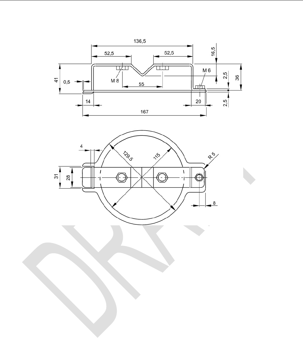
Universal holder
Figure 7-25 Universal holder 6GT2590-0QA00
RF300 transponder
7.8 SIMATIC RF380T
SIMATIC RF300
242 System Manual, 07/2016, C79000-G8976-C345-0x
7.8.3.2
Metal-free area
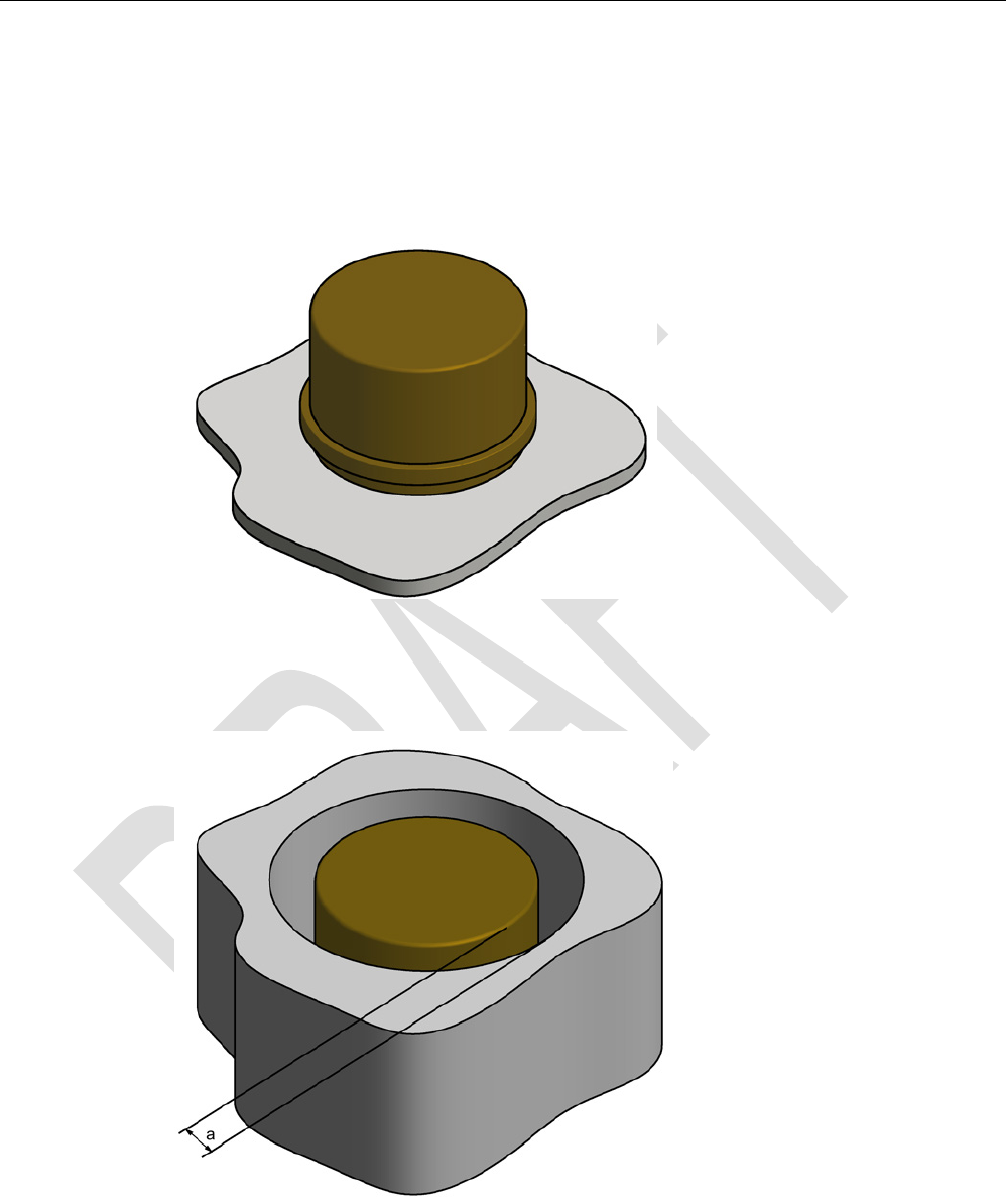
Direct mounting of the RF380T on metal is permitted.
Mounting of RF380T on metal
Figure 7-26 Mounting of RF380T on metal
Flush-mounting of RF380T in metal:
Figure 7-27 RF380T flush-mounted in metal
The standard value for a is ≥ 40 mm. At lower values, the field data change significantly,
resulting in a reduction in the range.

RF300 transponder
7.8 SIMATIC RF380T
SIMATIC RF300
System Manual, 07/2016, C79000-G8976-C345-0x 243
7.8.4
Configuring instructions
7.8.4.1
Temperature dependence of the transmission window
The guidelines in the section "Planning the RF300 system" apply to configuration of heat-
resistant data memories, with the exception of the limit distance and field length at
temperatures above 85 °C. At temperatures above 85 °C, the length of the transmission
window is reduced by up to 10%.
7.8.4.2
Temperature response in cyclic operation
At ambient temperatures (Tu) up to 110 °C, cyclic operation is not necessary, i.e. up to this
temperature, the transponder can be in constant operation.
Note
Calculation of the temperature curves
Calculation of the temperatur
e curves or of a temperature profile can be carried out on
request by Siemens AG. Exact knowledge of the internal temperature facilitates
configuration for time
-critical applications.
You can also carry out the calculation with the aid of the "SIMATIC RF T
emperature
Calculator" on the "Ident Systems Software & Documentation" DVD (refer to the section
"
DVD "Ident Systems Software & Documentation" (Page 416)").
Ambient temperatures > 110 °C
Note
Cancellation of warranty
The internal temperature of the data memory must not exceed the critical threshold of 110
°C. Each heating phase must be followed by a cooling phase. No warranty claims will
other
wise be accepted.
Some limit cycles are listed in the table below:
Table 7- 20 Limit cycles of data memory temperature
Tu (heating up)
Heating up
Tu (cooling down)
Cooling down
220 °C
0.5 h
25 °C
> 2 h
200 °C
1 h
25 °C
> 2 h
190 °C
1 h
25 °C
> 1 h 45 min
180 °C
2 h
25 °C
> 5 h
170 °C 2 h 25 °C > 4 h

RF300 transponder
7.8 SIMATIC RF380T
SIMATIC RF300
244 System Manual, 07/2016, C79000-G8976-C345-0x
The internal temperature of the tag follows an exponential function with which the internal
temperature and the operability of the tag can be calculated in advance. This is particularly
relevant to temperature-critical applications or those with a complex temperature profile.
Ambient temperatures > 220°C
Note
Cancellation of warranty
The data memory must not be exposed to ambient temperatures > 220 °C. No warranty
claims will otherwise be accepted.
However, the mechanical stability is retained up to 230 °C!
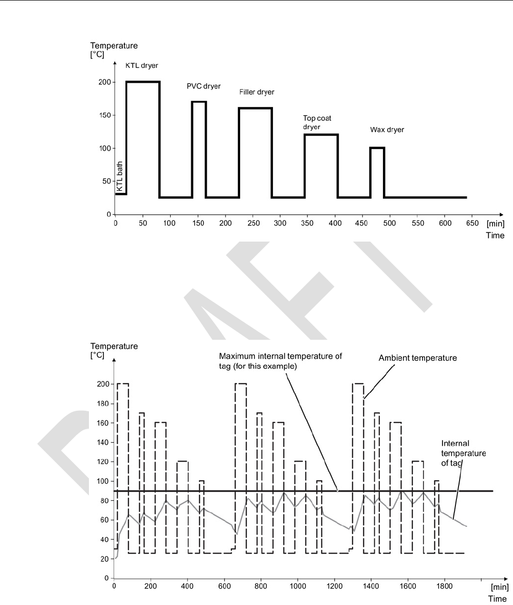
Example of a cyclic sequence
Table 7- 21 Typical temperature profile of an application in the paint shop
Start of tag at initial point
Duration (min)
Ambient temperature (°C)
Electrolytic dip
20
30
Electrolytic dip dryer
60
200
Transport
60
25
PVC dryer
25
170
Transport
60
25
Filler dryer
60
160
Transport
60
25
Top coat dryer
60
120
Transport
60
25
Wax dryer
25
100
Transport
150
25
RF300 transponder
7.8 SIMATIC RF380T
SIMATIC RF300
System Manual, 07/2016, C79000-G8976-C345-0x 245
Figure 7-28 Graphic trend of temperature profile from above table
The simulation results in the following:
Following a simulation time of 36.5 hours, a total of 3 cycles were carried out, and an internal
temperature of 90 degrees Celsius was reached.
Figure 7-29 Complete temperature response due to simulation
RF300 transponder
7.8 SIMATIC RF380T
SIMATIC RF300
246 System Manual, 07/2016, C79000-G8976-C345-0x
7.8.5
Use of the transponder in the Ex protection area
The TÜV SÜD Automotive GmbH as approved test center as well as the TÜV SÜD Product
Service GmbH as certification center, identification number 0123, as per Article 9 of the
Directive of the European Council of 23 March 1994 (94/9/EC), has confirmed the
compliance with the essential health and safety requirements relating to the design and
construction of equipment and protective systems intended for use in hazardous areas as
per Annex II of the Directive. The essential health and safety requirements are satisfied in
accordance with the following standards:
Table 7- 22 Approvals
Document
Title
EN 60079-0: 2006
Electrical equipment for hazardous gas atmospheres -
Part 0: General requirements
EN 60079-15: 2005 Electrical equipment for hazardous gas atmospheres -
Part 15: Design, testing and identification of electrical equipment
with type of protection "n"
DIN VDE 0848-5: 2001
(in parts)
Safety in electrical, magnetic and electromagnetic fields -
Part 5: Explosion protection
ZLS SK 107.1
Central office of the states for safety; test components
Identification
Table 7- 23 The identification of the electrical equipment as an encapsulated unit
II 3G Ex nC IIB T5
-25°C to +70°C
Um=30Vdc
The equipment is assigned the following references:
XXXYYYZZZ
[= serial number, is assigned during production]
TPS 09 ATEX 1 459 X
[= certificate number]
"No use of the equipment in the vicinity of processes generating high charges"
7.8.5.1
Use of the transponder in hazardous areas for gases
Temperature class delineation for gases
The temperature class of the transponder for hazardous areas depends on the ambient
temperature range:
Ambient temperature range
Temperature class
-25 °C to +70 °C
T5

RF300 transponder
7.8 SIMATIC RF380T
SIMATIC RF300
System Manual, 07/2016, C79000-G8976-C345-0x 247
WARNING
Ignitions of gas-air mixtures
• When using the RF380T transponder, check that the temperature class is kept to in
conjunction with the requirements of the area of application.
If the temperature ranges are exceeded during use of the transponder, gas-air mixtures
may be ignited.
• The maximum transmit power of the transmitter used to operate the transponder must
not exceed 2 W.
If the transmit power id not kept to, gas-air mixtures may ignite.
7.8.5.2
Installation and operating conditions for the hazardous area
a) Use of the equipment in the vicinity of processes generating high charges is not allowed.
b) The equipment must be mechanically protected when installed.
7.8.6
Cleaning the mobile data memory
Note
Do not clean the transponder with mechanical tools, sand
-blasting or pressure hose. These
cleaning methods result in damage to the transponder.
Clean the transponder only with the chemical cleansing agents listed in Chapter
Chemical
resistance of the transponders
(Page 90).
7.8.7
Technical specifications
Table 7- 24 RF380T technical specifications
6GT2800-5DA00
Product type designation
SIMATIC RF380T
Memory
Memory organization
in bytes
Memory configuration
• UID • 4 bytes EEPROM
• User memory • 32 KB FRAM
• OPT memory • 20 bytes EEPROM

RF300 transponder
7.8 SIMATIC RF380T
SIMATIC RF300
248 System Manual, 07/2016, C79000-G8976-C345-0x
6GT2800-5DA00
Read cycles (at < 40 ℃)
> 10
10
Write cycles (at < 40 ℃)
> 10
10
Data retention time (at < 40 ℃)
> 10 years
Write/read distance (Sg) Dependent on the reader used, see section "Field
data of RF300 transponders (Page 49)"
MTBF (Mean Time Between Failures)
1177 years
Mechanical specifications
Housing
• Material • PPS
• Color • Anthracite
Recommended distance to metal
≥ 0 mm
Power supply
Inductive, without battery
Permitted ambient conditions
Ambient temperature
• During operation • -25 to +110 ℃
• -25 … +220 ℃: cyclic operation possible
• During transportation and storage • -40 to +110 ℃
Degree of protection to EN 60529
IP68
Shock-resistant to EN 60721-3-7, Class 7 M3
50 g
1)2)
Vibration-resistant to EN 60721-3-7, Class 7 M3
5 g
2)
Torsion and bending load
Not permitted
Design, dimensions and weight
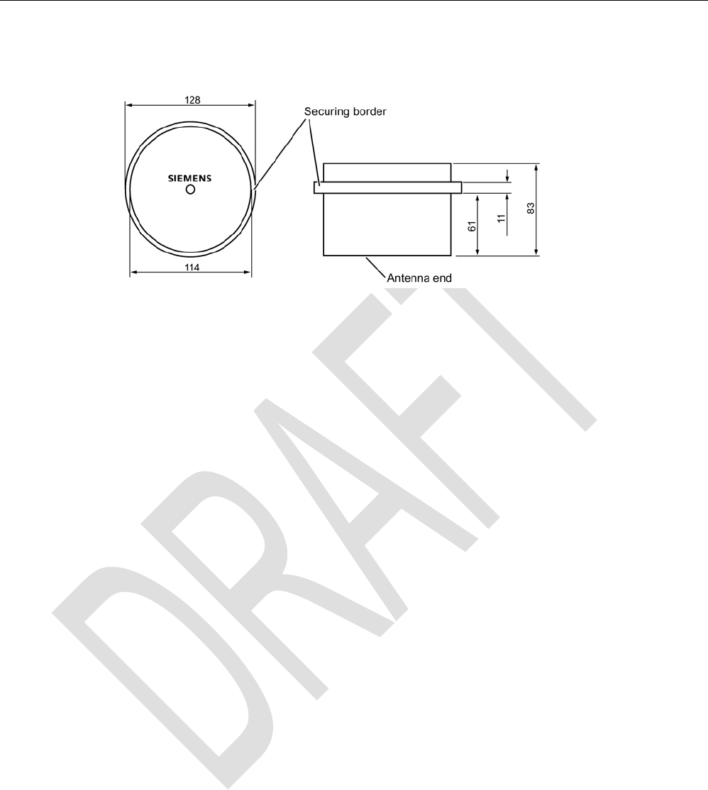
Dimensions (Ø x H) 114 x 83 mm
Weight 900 g
Type of mounting Holder (must be ordered separately)
1)
Applies only in conjunction with the original support
2) The values for shock and vibration are maximum values and must not be applied continuously.
RF300 transponder
7.8 SIMATIC RF380T
SIMATIC RF300
System Manual, 07/2016, C79000-G8976-C345-0x 249
7.8.8
Dimensional drawing
Figure 7-30 Dimension drawing RF380T
Dimensions in mm

RF300 transponder
7.8 SIMATIC RF380T
SIMATIC RF300
250 System Manual, 07/2016, C79000-G8976-C345-0x

SIMATIC RF300
System Manual, 07/2016, C79000-G8976-C345-0x 251
ISO transponder
8
Features of the ISO transponders
The transponders (MDS D) that are compatible with ISO 15693 represent a cost-effective
alternative to RF300 transponders. The performance that can be achieved with this
(transmission speed, memory size), however, is considerably less than with RF300
transponders.
You will find more information on transmission speeds in the section "Communication
between communications module, reader and transponder (Page 47)".
ISO transponder
8.1 Memory configuration of ISO the transponders
SIMATIC RF300
252 System Manual, 07/2016, C79000-G8976-C345-0x
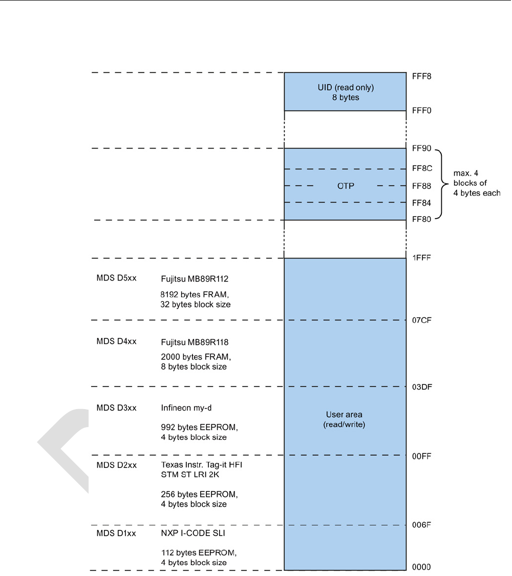
8.1
Memory configuration of ISO the transponders
Figure 8-1 Memory configuration of ISO the transponders

ISO transponder
8.1 Memory configuration of ISO the transponders
SIMATIC RF300
System Manual, 07/2016, C79000-G8976-C345-0x 253
Memory areas
Depending on the manufacturer of the transponder chip, the memory configuration of an ISO
transponder consists of varying sizes of user memory.
The typical sizes are 112 bytes, 256 bytes, 992 bytes EEPROM or 2000 bytes FRAM. Each
ISO transponder chip has an 8-byte long unique serial number (UID, read only). This UID is
transferred as an 8 byte value through a read command to address FFF0 with a length of 8.
OTP area
For the OTP area, a 16-byte address space is always reserved at the end of the memory
area. The blocks are divided up depending on the chip (see technical specifications). Note
that the corresponding addresses for the user data are therefore not available to the
application when the OTP area is used.
A total of 4 block addresses ("mapped" addresses) are provided:
● FF80
● FF84
● FF88
● FF8C
A write command to this block address with a valid length (4, 8, 12, 16 bytes depending on
the block address) protects the written data from subsequent overwriting.
Note
Exception Fujitsu chip (MDS D4xx and MDS D522)
The Fujitsu chip MB89R118 (MDS D4xx)
has 8-byte blocks, which means that only 2 block
addresses have to be addressed: FF80 and FF88 with the length 8 and 16 bytes).
The Fujitsu chip MB89R112 (MDS D5xx) has 32 byte blocks and can therefore not be
addressed in the OTP area.
Note
Restriction to the use of the OTP
Observe the following restrictions when using OTP:
•
The OTP write/lock command can only be sent in static operation.
•
The OTP write/lock command can not be sent as a chained command.
The Fujitsu chip MB89R112 (MDS D5xx) has 32 byte bl
ocks and can therefore not be
addressed in the OTP area.
Note
Use of the OTP area is not reversible
If you use the OPT area, you cannot undo it, because the OPT area can only be written to
once.
ISO transponder
8.2 MDS D100
SIMATIC RF300
254 System Manual, 07/2016, C79000-G8976-C345-0x
8.2
MDS D100
8.2.1
Characteristics
MDS D100
Characteristics
Area of application From simple identification such as electronic
barcode replacement/supplementation, through
warehouse and distribution logistics, right up to
product identification.
Memory size
112 bytes of EEPROM user memory
Write/read range See section Field data of ISO transponders
(MDS D) (Page 52).
Mounting on metal
Yes, with spacer
ISO standard
ISO 15693
Degree of protection
IP68
8.2.2
Ordering data
Table 8- 1 Ordering data for MDS D100
Article number
MDS D100
6GT2600-0AD10
Table 8- 2 Ordering data for MDS D100 accessory
Article number
Spacer
(in conjunction with fixing pocket 6GT2190-0AB00)
6GT2190-0AA00
Fixing pocket
(in conjunction with spacer 6GT2190-0AA00)
6GT2190-0AB00
Fixing pocket
(not suitable for fixing directly onto metal)
6GT2390-0AA00
8.2.3
Metal-free area
Direct mounting of the MDS D100 on metal is not allowed. A distance of ≥ 20 mm is
recommended. This can be achieved using the spacer 6GT2190-0AA00 in combination with
the fixing pocket 6GT2190-0AB00.
ISO transponder
8.2 MDS D100
SIMATIC RF300
System Manual, 07/2016, C79000-G8976-C345-0x 255
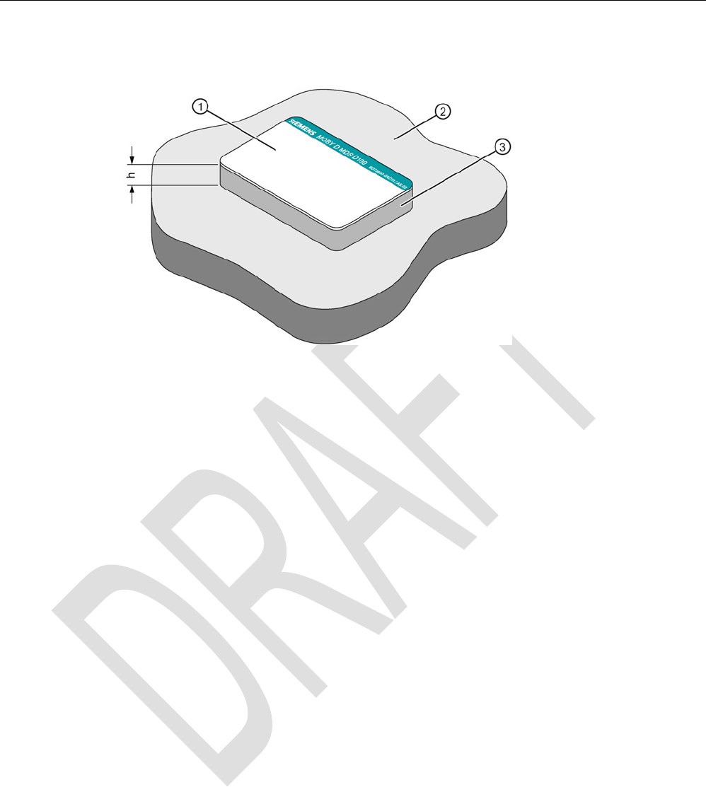
Mounting on metal
h
≥ 20 mm
①
Data memory
②
Metal
③
Non-metal
Figure 8-2 Mounting of the MDS D100 on metal with spacer
ISO transponder
8.2 MDS D100
SIMATIC RF300
256 System Manual, 07/2016, C79000-G8976-C345-0x
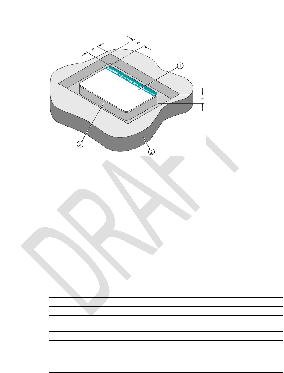
Flush-mounting
a
≥ 20 mm
h
≥ 20 mm
①
Data memory
②
Metal
③
Non-metal
Figure 8-3 Flush-mounting of MDS D100 in metal with spacer
Note
If the minimum guide values (h or a) are not observed, a reduction of the field data results.
8.2.4
Technical data
Table 8- 3 Technical specifications for MDS D100
6GT2600-0AD10
Product type designation
SIMATIC MDS D100
Memory
Memory configuration
• UID • 8 bytes
• User memory • 112 bytes EEPROM
• OPT memory • 16 bytes (EEPROM)

ISO transponder
8.2 MDS D100
SIMATIC RF300
System Manual, 07/2016, C79000-G8976-C345-0x 257
6GT2600-0AD10
Read cycles (at < 40 ℃)
> 10
14
Write cycles (at < 40 ℃)
> 10
6
Data retention time (at < 40 ℃)
> 10 years
Write/read distance (Sg) Dependent on the reader used, see section "Field
data of ISO transponders (MDS D) (Page 52)"
MTBF (Mean Time Between Failures)
228 years
Mechanical specifications
Housing
• Material • PC
• Color • White/petrol
Recommended distance to metal
≥ 20 mm
Power supply
Inductive, without battery
Permitted ambient conditions
Ambient temperature
• During operation • -25 to +80 ℃
• During transportation and storage • -25 to +80 ℃
Degree of protection to EN 60529 • IP68
Shock-resistant to EN 60721-3-7 class 7M3
ISO 10373 / ISO 7810
1)
Vibration-resistant to EN 60721-3-7, class 7M3
ISO 10373 / ISO 7810
1)
Torsion and bending load
ISO 10373/ISO 7816-1
Design, dimensions and weight
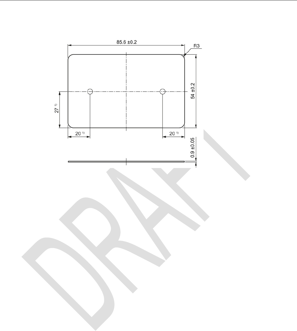
Dimensions (L x W x H)
85.6 x 54 x 0.9 mm
Weight 5 g
Type of mounting • Fixing pocket
• Glued
1) The values for shock and vibration are maximum values and must not be applied continuously.
ISO transponder
8.2 MDS D100
SIMATIC RF300
258 System Manual, 07/2016, C79000-G8976-C345-0x
8.2.5
Dimension drawing
Dimensions in mm
1)
Dimensions for mounting holes
Figure 8-4 MDS D100 dimension drawing
ISO transponder
8.3 MDS D117
SIMATIC RF300
System Manual, 07/2016, C79000-G8976-C345-0x 259
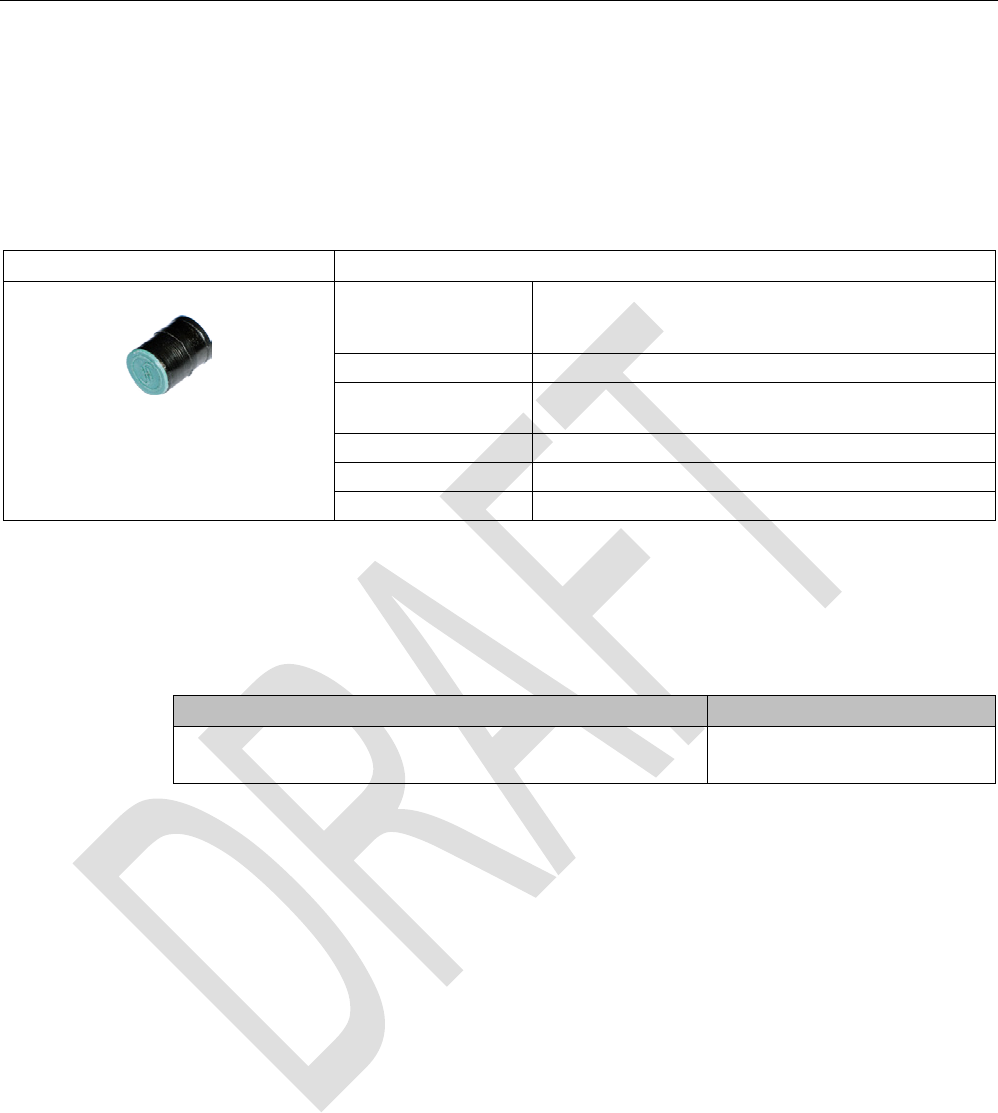
8.3
MDS D117
8.3.1
Features
MDS D117
Characteristics
Area of application Very compact data carrier that can be cemented into
objects where precise positioning is necessary;
e.g. tool identification, workpiece holders etc..
Memory size 112 bytes of EEPROM user memory
Write/read range See section "Field data of ISO transponders (MDS D)
(Page 52)."
Mounting in metal
Yes, flush-mounted in metal
ISO standard
ISO 15693
Degree of protection
IP68/IPx9K
8.3.2
Ordering data
Table 8- 4 Ordering data for MDS D117
Article number
MDS D117
Pack of 10
6GT2600-0AG00
ISO transponder
8.3 MDS D117
SIMATIC RF300
260 System Manual, 07/2016, C79000-G8976-C345-0x
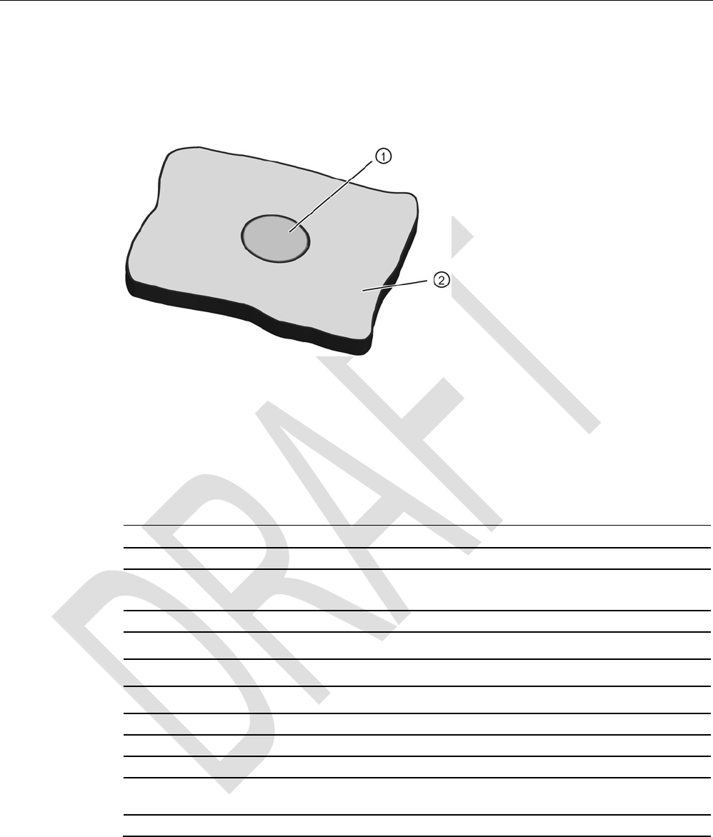
8.3.3
Mounting in metal
Flush-mounted in metal
①
Transponder
②
Metal
8.3.4
Technical specifications
Table 8- 5 Technical specifications for MDS D117
6GT2600-0AG00
Product type designation
SIMATIC MDS D117
Memory
Memory configuration
• UID • 8 bytes
• User memory • 112 bytes EEPROM
• OPT memory • 16 bytes (EEPROM)
Read cycles (at < 40 ℃)
> 10
14
Write cycles (at < 40 ℃)
> 10
6
Data retention time (at < 40 ℃)
> 10 years
Write/read distance (Sg) Dependent on the reader used, see section "Field
data of ISO transponders (MDS D) (Page 52)"
MTBF (Mean Time Between Failures)
228 years
ISO transponder
8.3 MDS D117
SIMATIC RF300
System Manual, 07/2016, C79000-G8976-C345-0x 261
6GT2600-0AG00
Mechanical specifications
Housing
• Material • PPS
• Color • Black
Recommended distance to metal
≥ 0 mm
Power supply
Inductive, without battery
Permitted ambient conditions
Ambient temperature
• During operation • -25 to +85 ℃
• During transportation and storage • -40 to +125 ℃
Degree of protection to EN 60529 IP68
2 hours, 2 bar, +20 °C
Shock-resistant to EN 60721-3-7 class 7M3
100 g
1)
Vibration-resistant to EN 60721-3-7, class 7M3
20 g
1)
Torsion and bending load
Not permitted
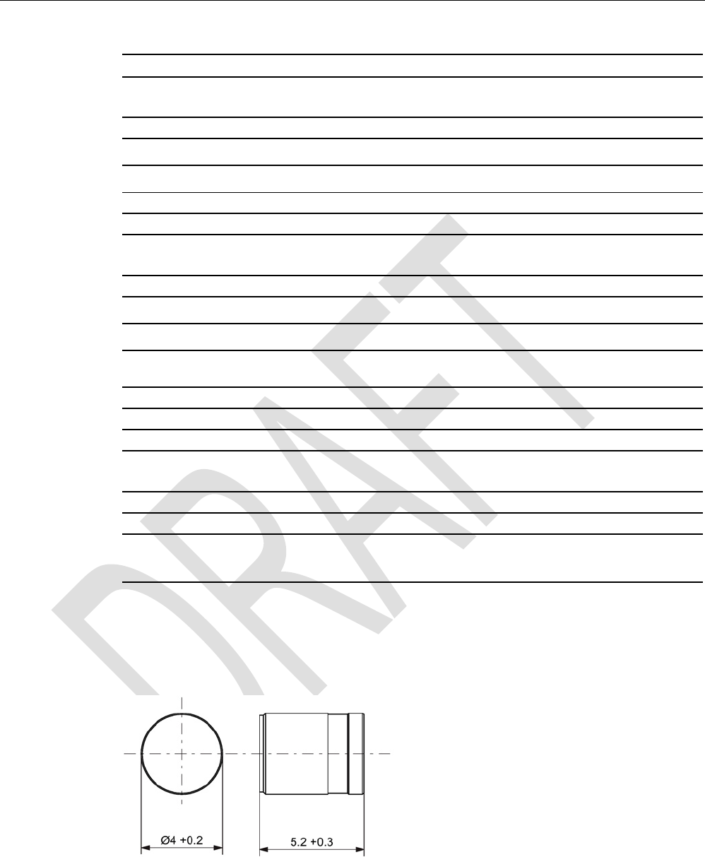
Design, dimensions and weight
Dimensions (Ø x H)
4 x 5.2 mm
Weight
1 g
Type of mounting • Fixing pocket
• Glued
1) The values for shock and vibration are maximum values and must not be applied continuously.
8.3.5
Dimension drawing
Figure 8-5 Dimensions in mm
ISO transponder
8.4 MDS D124
SIMATIC RF300
262 System Manual, 07/2016, C79000-G8976-C345-0x
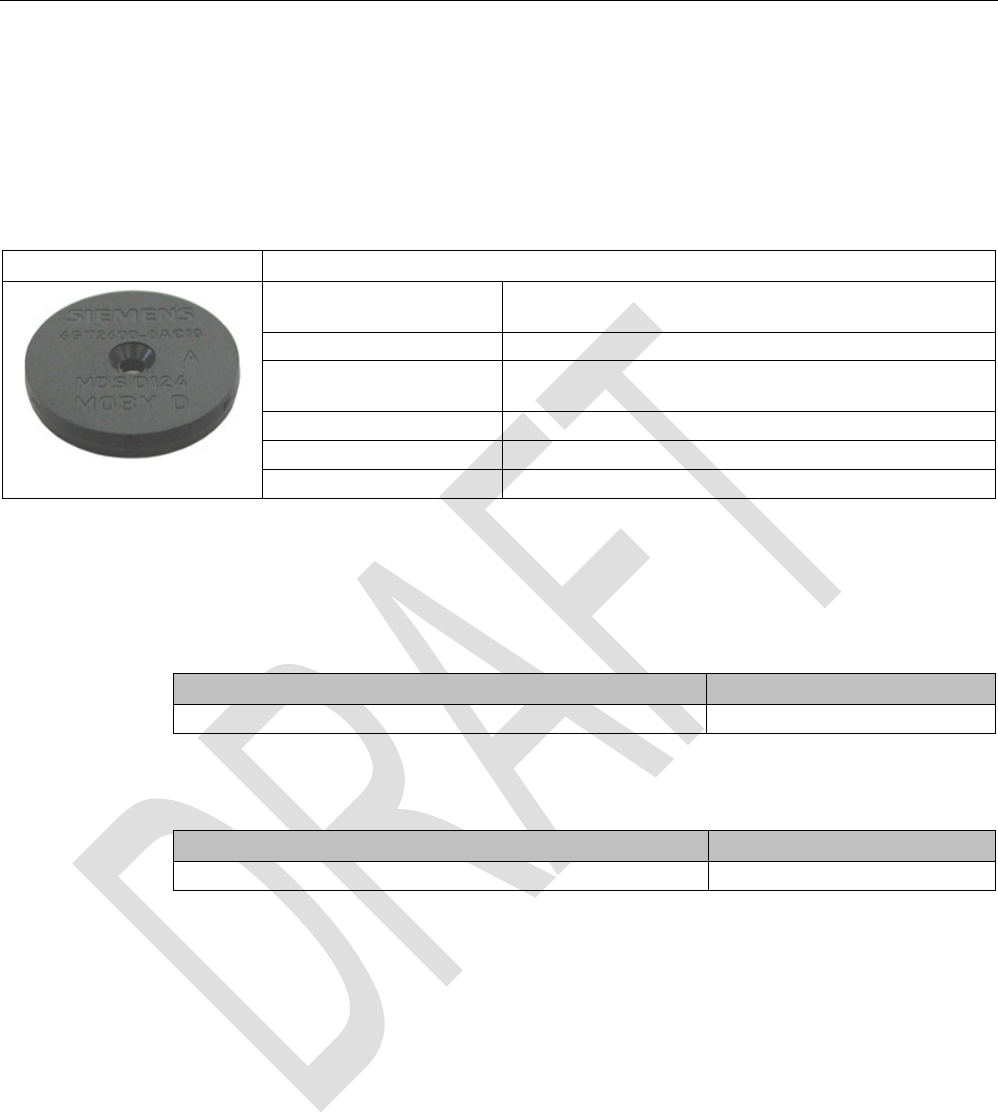
8.4
MDS D124
8.4.1
Characteristics
MDS D124
Characteristics
Area of application Application areas in production automation (e.g. small
paintshops up to +180 °C)
Memory size
112 bytes of EEPROM user memory
Write/read range See section "Field data of ISO transponders (MDS D)
(Page 52)".
Mounting on metal
Yes, with spacer
ISO standard
ISO 15693
Degree of protection
IP68/IPx9K
8.4.2
Ordering data
Table 8- 6 Ordering data for MDS D124
Article number
MDS D124
6GT2600-0AC10
Table 8- 7 Ordering data for MDS D124 accessories
Article number
Spacer
6GT2690-0AK00

ISO transponder
8.4 MDS D124
SIMATIC RF300
System Manual, 07/2016, C79000-G8976-C345-0x 263
8.4.3
Mounting on metal
Mounting on metal
h
≥ 15 mm
Figure 8-6 Mounting the MDS D124/D324/D424/D524/E624 and RF320T on metal with spacer
Flush-mounting
h
≥ 15 mm
a
≥ 25 mm
Figure 8-7 Flush-mounting of the MDS D124/D324/D424/D524/E624 and RF320T in metal with
spacer

ISO transponder
8.4 MDS D124
SIMATIC RF300
264 System Manual, 07/2016, C79000-G8976-C345-0x
Note
Going below the distances
If the distances (a and h) are not observed, a reduction of the field data results. It i
s possible
to mount the MDS with metal screws (M3 countersunk head screws). This has no tangible
impact on the range.
8.4.4
Technical specifications
Table 8- 8 Technical specifications for MDS D124
6GT2600-0AC10
Product type designation
SIMATIC MDS D124
Memory
Memory configuration
• UID • 8 bytes
• User memory • 112 bytes EEPROM
• OPT memory • 16 bytes (EEPROM)
Read cycles (at < 40 ℃)
> 10
14
Write cycles (at < 40 ℃)
> 10
6
Data retention time (at < 40 ℃)
> 10 years
Write/read distance (Sg) Dependent on the reader used, see section "Field
data of ISO transponders (MDS D) (Page 52)"
MTBF (Mean Time Between Failures)
228 years
Mechanical specifications
Housing
• Material • PPS
• Color • Black
Recommended distance to metal
≥ 15 mm
Power supply
Inductive, without battery
Permitted ambient conditions
Ambient temperature
• During operation • -25 to +180 ℃
• from +125 ℃: 20% reduction in the limit dis-
tance
• from +140 ℃: No processing possible

ISO transponder
8.4 MDS D124
SIMATIC RF300
System Manual, 07/2016, C79000-G8976-C345-0x 265
6GT2600-0AC10
• at +180 ℃: Tested up to 5000 hours or
3000 cycles
• During transportation and storage • -40 to +125 ℃
Degree of protection to EN 60529 • IP68
2 hours, 2 bar, +20 °C
• IPx9K
steam jet: 150 mm; 10 to 15 l/min; 100 bar; 75
°C
Shock-resistant to EN 60721-3-7 class 7M3
100 g
1)
Vibration-resistant to EN 60721-3-7, class 7M3
20 g
1)
Torsion and bending load
Not permitted
Design, dimensions and weight
Dimensions (Ø x H)
4 x 5.2 mm
Weight
5 g
Type of mounting • 1 x M3 screw 2)
≤ 1 Nm
• Glued
• With spacer
1)
The values for shock and vibration are maximum values and must not be applied continuously.
2 ) To prevent it loosening during operation, secure the screw with screw locking varnish.
8.4.5
Use of the MDS D124 in hazardous area
The mobile data memory MDS D124, device group II, category 1G or 1D may be installed
and operated in zones 0, 1 and 2 or in the zones 20, 21 and 22.
The following requirements of the 94/9/EC directive are met:
● EN 60079-0:2009
● EN 60079-11:2007
● EN 61241-11:2006
● EN 60079-26:2007
When used in hazardous areas, the MDS D124 must not be operated with field strengths > 5
A / m to avoid impermissible heating. This is not the case with readers from the SIMATIC RF
range (MOBY D, RF200 and RF300).
ISO transponder
8.4 MDS D124
SIMATIC RF300
266 System Manual, 07/2016, C79000-G8976-C345-0x
Identification
II 1 G Ex ia IIC T3 to T6 Ga
or
II 1 D Ex ia IIIC T80 °C to T180 °C Da
TÜV 12 ATEX 084413 X
The temperature class or the maximum surface temperature depends on the maximum
ambient temperature. The relationship between temperature class (gas) or maximum surface
temperature (dust) can be found in the following table.
Table 8- 9 Ambient temperature
Ambient temperature range
Temperature class
Max. surface temperature
-25 ... +150 ℃
T3
T180
-25 ... +100 ℃
T4
T130
-25 ... +65 ℃
T5
T95
-25 ... +50 ℃
T6
T80
Note
Safety markings for hazardous areas
Since there is not enough space on the MDS D124 for the safety mark, this is supplied as a
label with the device.
This must be affixed immediately next to the MDS D124 so that the label clearly relates to
th
e device.
WARNING
Gefahr durch elektrostatische Entladungen
Potential electrostatic charging hazard
Danger potentiel de charges électrostatiques
ISO transponder
8.4 MDS D124
SIMATIC RF300
System Manual, 07/2016, C79000-G8976-C345-0x 267
Note
Installation and operating conditions for hazardous areas:
•
Use of the device in the vicinity of processes generating high charges is not allowed.
•
The device must be installed so that it is mechanically protected.
•
For applications requiring devices of category 1, the device must be mounted on a
grounded, conductive base.
•
It must only be cleaned with a damp cloth.
•
The device is suitable for use in atmospheres containing dust, however not for full
immersion in dust.
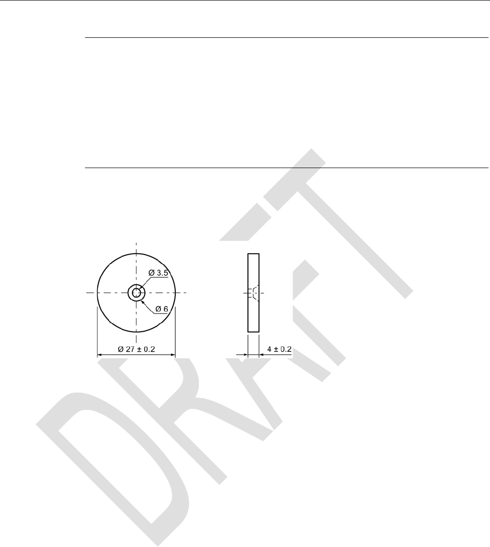
8.4.6
Dimension drawing
Figure 8-8 Dimension drawing of MDS D124
All dimensions in mm
ISO transponder
8.5 MDS D126
SIMATIC RF300
268 System Manual, 07/2016, C79000-G8976-C345-0x
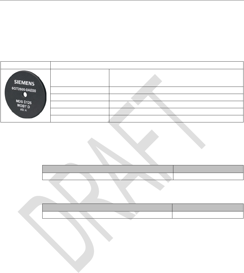
8.5
MDS D126
8.5.1
Characteristics
MDS D126
Characteristics
Area of application Compact and rugged ISO transponder; suitable for identification of
transport units in production-
related logistics; can also be deployed
in harsh conditions
Memory size 112 bytes of EEPROM user memory
Write/read range
See section Field data of ISO transponders (MDS D) (Page 52)
Mounting on metal
Yes, with spacer
ISO standard
ISO-15693
Degree of protection
IP68
8.5.2
Ordering data
Table 8- 10 Ordering data for MDS D126
Article number
MDS D126
6GT2600-0AE00
Table 8- 11 Ordering data for MDS D126 accessories
Article number
Spacer
6GT2690-0AL00
ISO transponder
8.5 MDS D126
SIMATIC RF300
System Manual, 07/2016, C79000-G8976-C345-0x 269
8.5.3
Mounting on metal
Mounting on metal
h
≥ 25 mm
Figure 8-9 Mounting the MDS D126 / D426 / D526 on metal with spacer
Flush-mounted in metal
h
≥ 25 mm
a
≥ 50 mm
Figure 8-10 Flush installation of the MDS D126 / D426 / D526 in metal with spacer

ISO transponder
8.5 MDS D126
SIMATIC RF300
270 System Manual, 07/2016, C79000-G8976-C345-0x
8.5.4
Technical specifications
Table 8- 12 Technical specifications for the MDS D126
6GT2600-0AE00
Product type designation
SIMATIC MDS D126
Memory
Memory configuration
• UID • 8 bytes
• User memory • 112 bytes EEPROM
• OPT memory • 16 bytes (EEPROM)
Read cycles (at < 40 ℃)
> 10
14
Write cycles (at < 40 ℃)
> 10
6
Data retention time (at < 40 ℃)
> 10 years
Write/read distance (Sg) Dependent on the reader used, see section "Field
data of ISO transponders (MDS D) (Page 52)"
MTBF (Mean Time Between Failures)
228 years
Mechanical specifications
Housing
• Material • PA6.6 GF
• Color • Black
Recommended distance to metal
≥ 25 mm
Power supply
Inductive, without battery
Permitted ambient conditions
Ambient temperature
• During operation • -25 to +85 ℃
• During transportation and storage • -40 to +100 ℃
Degree of protection to EN 60529 IP68
2 hours, 2 bar, +20 °C
Shock-resistant to EN 60721-3-7 class 7M3
50 g
1)
Vibration-resistant to EN 60721-3-7, class 7M3
20 g
1)
Torsion and bending load Not permitted
ISO transponder
8.5 MDS D126
SIMATIC RF300
System Manual, 07/2016, C79000-G8976-C345-0x 271
6GT2600-0AE00
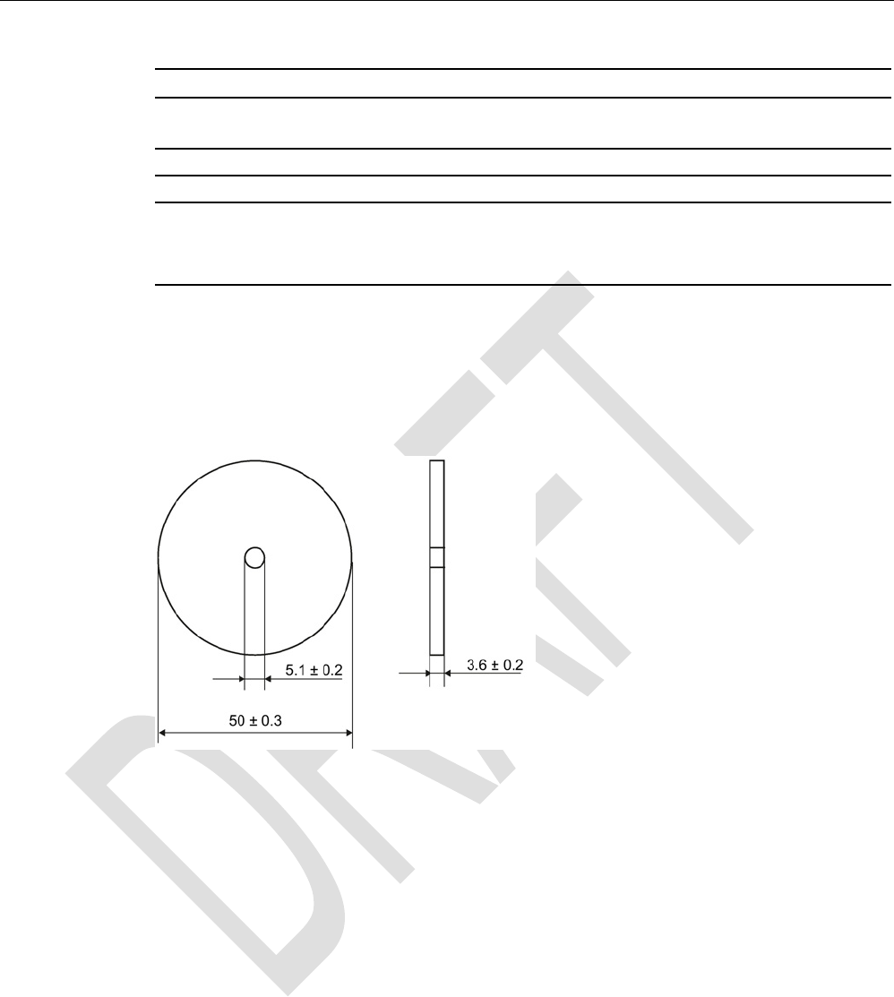
Design, dimensions and weight
Dimensions (Ø x H)
50 x 3.6 mm
Weight
13 g
Type of mounting • 1 x M4 screw 2)
≤ 1 Nm
• Glued
1)
The values for shock and vibration are maximum values and must not be applied continuously.
2 ) To prevent it loosening during operation, secure the screw with screw locking varnish.
8.5.5
Dimension drawing
Dimensions in mm
Figure 8-11 Dimension drawing of MDS D126
ISO transponder
8.6 MDS D127
SIMATIC RF300
272 System Manual, 07/2016, C79000-G8976-C345-0x
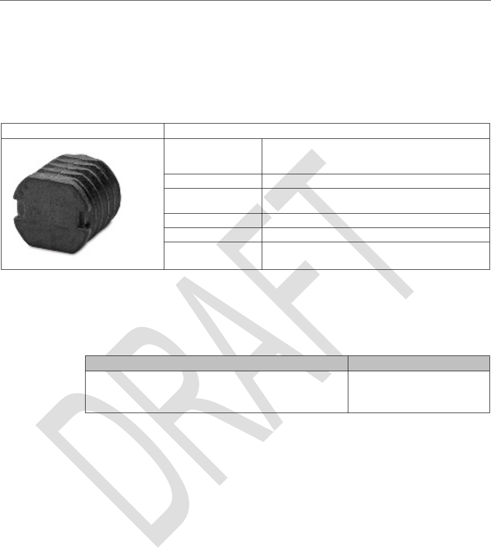
8.6
MDS D127
8.6.1
Features
MDS D127
Characteristics
Area of application Very compact data carrier that can be screwed into
areas where precise positioning is necessary;
e.g. tool identification, workpiece holders etc.
Memory size 112 bytes of EEPROM user memory
Write/read range See section "Field data of ISO transponders (MDS D)
(Page 52)"
Mounting on metal
Yes, flush-mounted in metal
ISO standard
ISO 15693
Degree of protection IP68/IPx9K
8.6.2
Ordering data
Table 8- 13 Ordering data for MDS D127
Article number
MDS D127
Pack of 10
(A screw-in aid is supplied with each pack)
6GT2600-0AF00
ISO transponder
8.6 MDS D127
SIMATIC RF300
System Manual, 07/2016, C79000-G8976-C345-0x 273
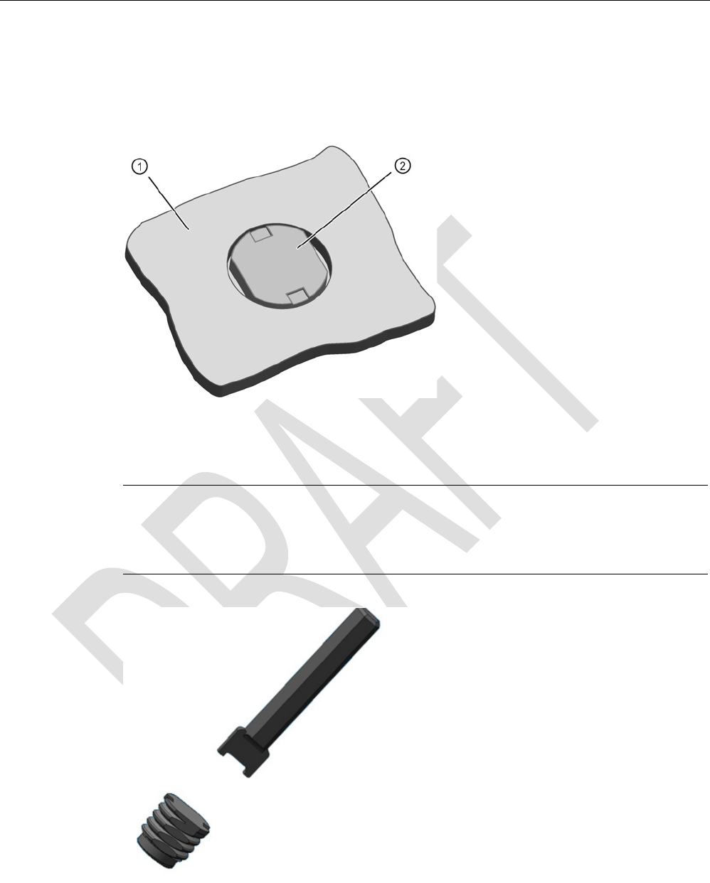
8.6.3
Mounting in metal
Flush-mounted in metal
①
Metal
②
Transponders
Note
Damage to the transponder due to improper mounting
To screw the MDS D127 into a suitable thread, use the supplied screw
-in tool. This avoids
damage to the MDS D127.
Figure 8-12 Screw-in aid for mounting the MDS D127

ISO transponder
8.6 MDS D127
SIMATIC RF300
274 System Manual, 07/2016, C79000-G8976-C345-0x
8.6.4
Technical specifications
Table 8- 14 Technical specifications for MDS D127
6GT2600-0AF00
Product type designation
SIMATIC MDS D127
Memory
Memory configuration
• UID • 8 bytes
• User memory • 112 bytes EEPROM
• OPT memory • 16 bytes (EEPROM)
Read cycles (at < 40 ℃)
> 10
14
Write cycles (at < 40 ℃)
> 10
6
Data retention time (at < 40 ℃)
> 10 years
Write/read distance (Sg) Dependent on the reader used, see section "Field
data of ISO transponders (MDS D) (Page 52)"
MTBF (Mean Time Between Failures)
228 years
Mechanical specifications
Housing
• Material • PA6
• Color • Black
Recommended distance to metal
≥ 0 mm
Power supply
Inductive, without battery
Permitted ambient conditions
Ambient temperature
• During operation • -25 to +100 ℃
• During transportation and storage • -40 to +125 ℃
Degree of protection to EN 60529 • IP68
2 hours, 2 bar, +20 °C
• IPx9K
steam jet: 150 mm; 10 to 15 l/min; 100 bar; 75
°C
Shock-resistant to EN 60721-3-7 class 7M3
100 g
1)
Vibration-resistant to EN 60721-3-7, class 7M3
20 g
1)
Torsion and bending load Not permitted
ISO transponder
8.6 MDS D127
SIMATIC RF300
System Manual, 07/2016, C79000-G8976-C345-0x 275
6GT2600-0AF00
Design, dimensions and weight
Dimensions (Ø x H)
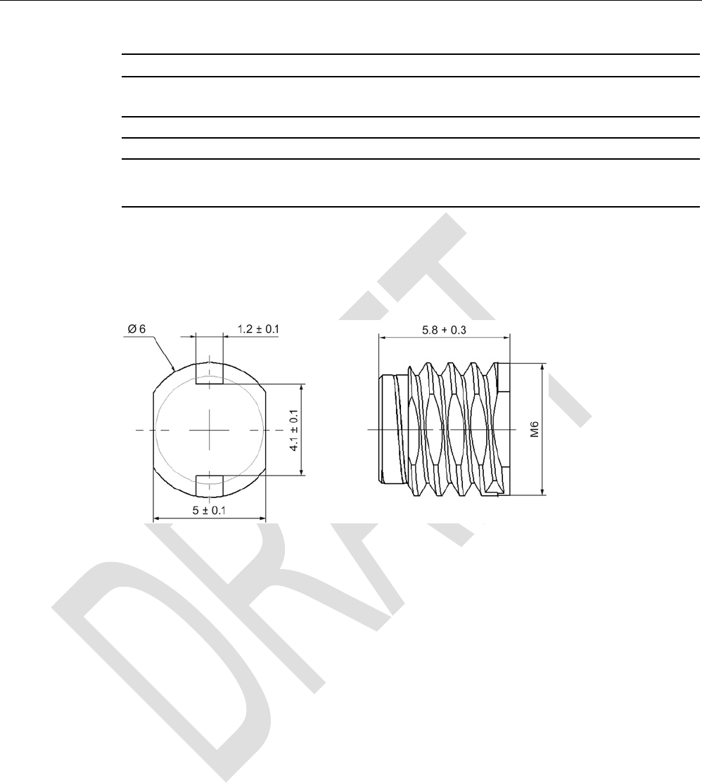
M6 x 5.8 mm
Weight
1 g
Type of mounting • Glued
• 1 x M3 screw
1) The values for shock and vibration are maximum values and must not be applied continuously.
8.6.5
Dimension drawing
Figure 8-13 Dimensions in mm
ISO transponder
8.7 MDS D139
SIMATIC RF300
276 System Manual, 07/2016, C79000-G8976-C345-0x
8.7
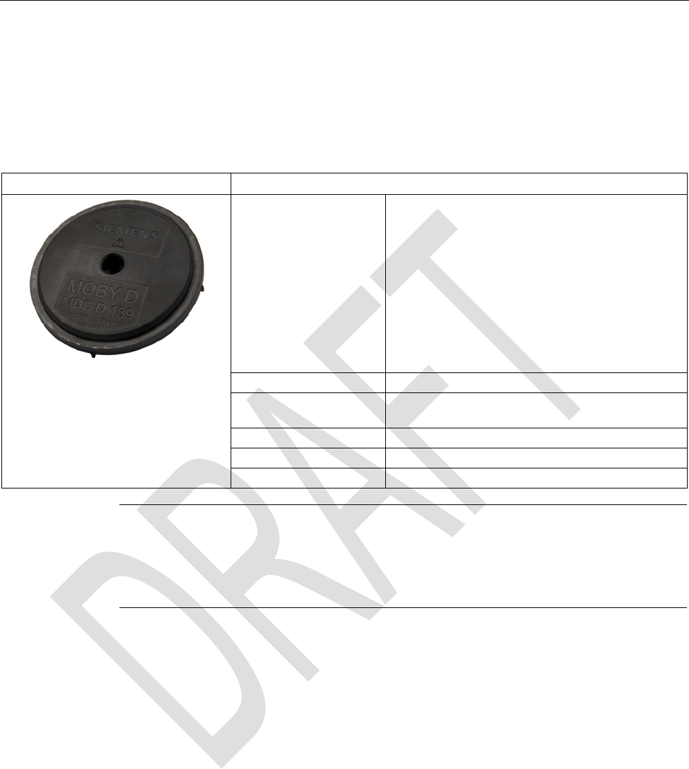
MDS D139
8.7.1
Characteristics
MDS D139
Characteristics
Area of application Applications in production logistics and in assembly
lines subject to high temperatures (up to +220 °C)
Typical application areas:
• Paintshops and their preparatory treatments)
• Primer coat, electrolytic dip area, cataphoresis
with the associated drying furnaces
• Top coat area with drying furnaces
• Washing areas at temperatures > 85 °C
• Other applications with higher temperatures
Memory size 112 bytes of EEPROM user memory
Write/read range See section Field data of ISO transponders (MDS D)
(Page 52).
Mounting on metal
Yes, with spacer
ISO standard
ISO 15693
Degree of protection
IP68/IPx9K
Note
Compatibility with SIMATIC RF300 depending on the article number
The transponder MDS D139 with article numbe
r 6GT2600-0AA10 is compatible with the
SIMATIC RF300 system. The transponder MDS D139 with article number 6GT2600
-0AA00
is not compatible.
ISO transponder
8.7 MDS D139
SIMATIC RF300
System Manual, 07/2016, C79000-G8976-C345-0x 277
8.7.2
Ordering data
Table 8- 15 Ordering data for MDS D139
Article number
MDS D139
6GT2600-0AA10
Table 8- 16 Ordering data for MDS D139 accessory
Article number
Spacer
6GT2690-0AA00
Quick change holder
(Ø x H): 22 x 60 mm
6GT2690-0AH00
Quick change holder
(Ø x H): 22 x 47 mm
6GT2690-0AH10
8.7.3
Mounting on metal
Direct mounting of the MDS D139/D339 on metal is not allowed. A distance of ≥ 30 mm is
recommended. This can be achieved using spacers (see "Ordering data (Page 423)").
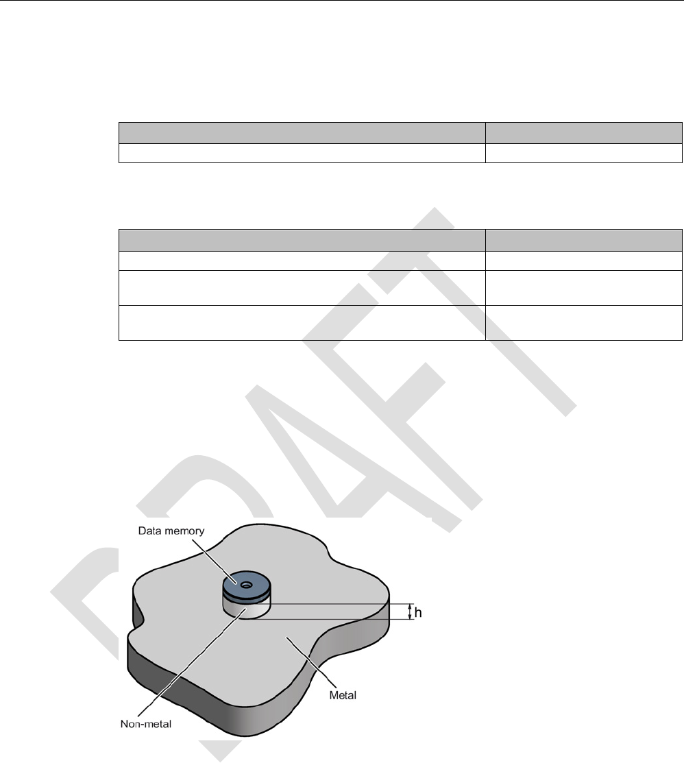
Mounting on metal
h
≥ 30 mm
Figure 8-14 Mounting the MDS D139/D339 on metal with spacer
ISO transponder
8.7 MDS D139
SIMATIC RF300
278 System Manual, 07/2016, C79000-G8976-C345-0x
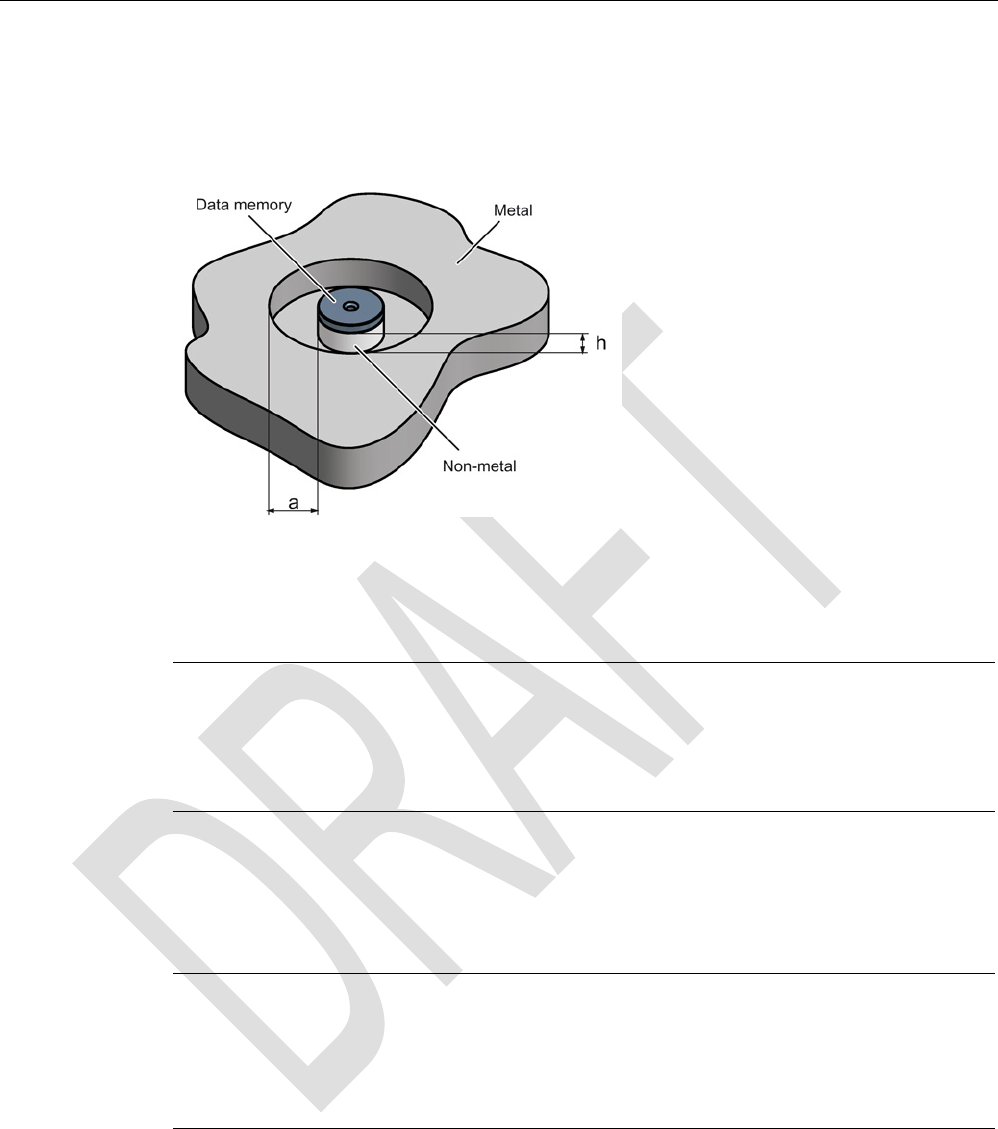
Flush-mounting
It is possible to mount the MDS D139/D339 in metal. With large antennas, for example ANT
D5, this leads to a reduction of ranges.
h
≥ 30 mm
a
≥ 100 mm
Figure 8-15 Flush-mounting of the MDS D139/D339 in metal with spacer
Note
Going below the distances
If the distances (a and h) are not observed, a reduction of the field data results. It is possible
to mount the MDS
with metal screws (M5). This has no tangible impact on the range. It is
recommended that a test is performed in critical applications.
8.7.4
Cleaning the mobile data memory
Note
Do not clean the transponder with mechanical tools, sand
-blasting or pressure hose. These
cleaning methods result in damage to the transponder.
Clean the transponder only with the chemical cleansing agents listed in Chapter
Chemical
resistance of the transponders
(Page 90).

ISO transponder
8.7 MDS D139
SIMATIC RF300
System Manual, 07/2016, C79000-G8976-C345-0x 279
8.7.5
Technical specifications
Table 8- 17 Technical specifications for MDS D139
6GT2600-0AA10
Product type designation
SIMATIC MDS D139
Memory
Memory configuration
• UID • 8 bytes
• User memory • 112 bytes EEPROM
• OPT memory • 16 bytes (EEPROM)
Read cycles (at < 40 ℃)
> 10
14
Write cycles (at < 40 ℃)
> 10
6
Data retention time (at < 40 ℃)
> 10 years
Write/read distance (Sg) Dependent on the reader used, see section "Field
data of ISO transponders (MDS D) (Page 52)"
MTBF (Mean Time Between Failures)
228 years
Mechanical specifications
Housing
• Material • PPS
• Color • Black
Recommended distance to metal
≥ 30 mm
Power supply
Inductive, without battery
Permitted ambient conditions
Ambient temperature
• During operation • -25 to +220 ℃
• from +125 ℃: 20% reduction in the limit dis-
tance
• from +140 ℃: No processing possible
• at +200 ℃: Tested up to 5000 hours or
6000 cycles
• at +220 ℃: Tested up to 2000 hours or
2000 cycles
• During transportation and storage • -40 to +100 ℃

ISO transponder
8.7 MDS D139
SIMATIC RF300
280 System Manual, 07/2016, C79000-G8976-C345-0x
6GT2600-0AA10
Degree of protection to EN 60529 • IP68
2 hours, 2 bar, +20 °C
• IPx9K
steam jet: 150 mm; 10 to 15 l/min; 100 bar; 75
°C
Shock-resistant to EN 60721-3-7 class 7M3
50 g
1)
Vibration-resistant to EN 60721-3-7, class 7M3
20 g
1)
Torsion and bending load
Not permitted
Design, dimensions and weight
Dimensions (Ø x H)
85 x 15 mm
Weight
50 g
Type of mounting 1 x M5 screw 2)
1.5 Nm
1
The values for shock and vibration are maximum values and must not be applied continuously.
2)
For mounting with the spacer (6GT2690-0AA00), use a stainless steel M5 screw to avoid damag-
ing the MDS in high temperatures (expansion coefficient).
8.7.6
Use of the MDS D139 in hazardous areas
The MDS D139 mobile data memory is classed as a piece of simple, electrical equipment
and can be operated in Protection Zone 2, Device Group II, Category 3G.
The following requirements of the 94/9/EC directive are met:
● EN 60079-0:2006
● EN 60079-15:2005
● EN 61241-0:2006
● EN 61241-1:2004
Identification
II 3 G Ex nA II T2
II 3 D Ex tD A22 IP68 T 220°C
KEMA 09 ATEX 0133 X
Ta: -25 ... +220°C

ISO transponder
8.7 MDS D139
SIMATIC RF300
System Manual, 07/2016, C79000-G8976-C345-0x 281
WARNING
Gefahr durch elektrostatische Entladungen
Potential electrostatic charging hazard
Danger potentiel de charges électrostatiques
Note
Installations- und Betriebsbedingungen für den Ex-Schutzbereich:
a) Der Einsatz des Gerätes in d
er Nähe von stark ladungserzeugenden Prozessen ist
untersagt.
b) Das Gerät ist mechanisch geschützt zu montieren.
c) Die Montage muss auf einem geerdeten, leitenden Untergrund erfolgen.
d) Die Reinigung darf nur mit feuchtem Tuch erfolgen.
Installation and operating conditions for hazardous areas:
a) Use of the equipment in the vicinity of processes generating high charges is not allowed.
b) The equipment must be mechanically protected when installed.
c) Installation must be performed on a grounded and con
ductive mounting surface.
d) Cleaning only with a wet cloth
Conditions d'installation et de mise en oeuvre pour la zone de protection Ex :
a) L'utilisation de l'appareil près de processus générant de fortes charges est interdite.
b) L'appareil doit être m
onté de manière à être protégé mécaniquement.
c) Le montage doit être effectué sur un socle conducteur mis à la terre.
d) Nettoyage uniquement avec un chiffon humide
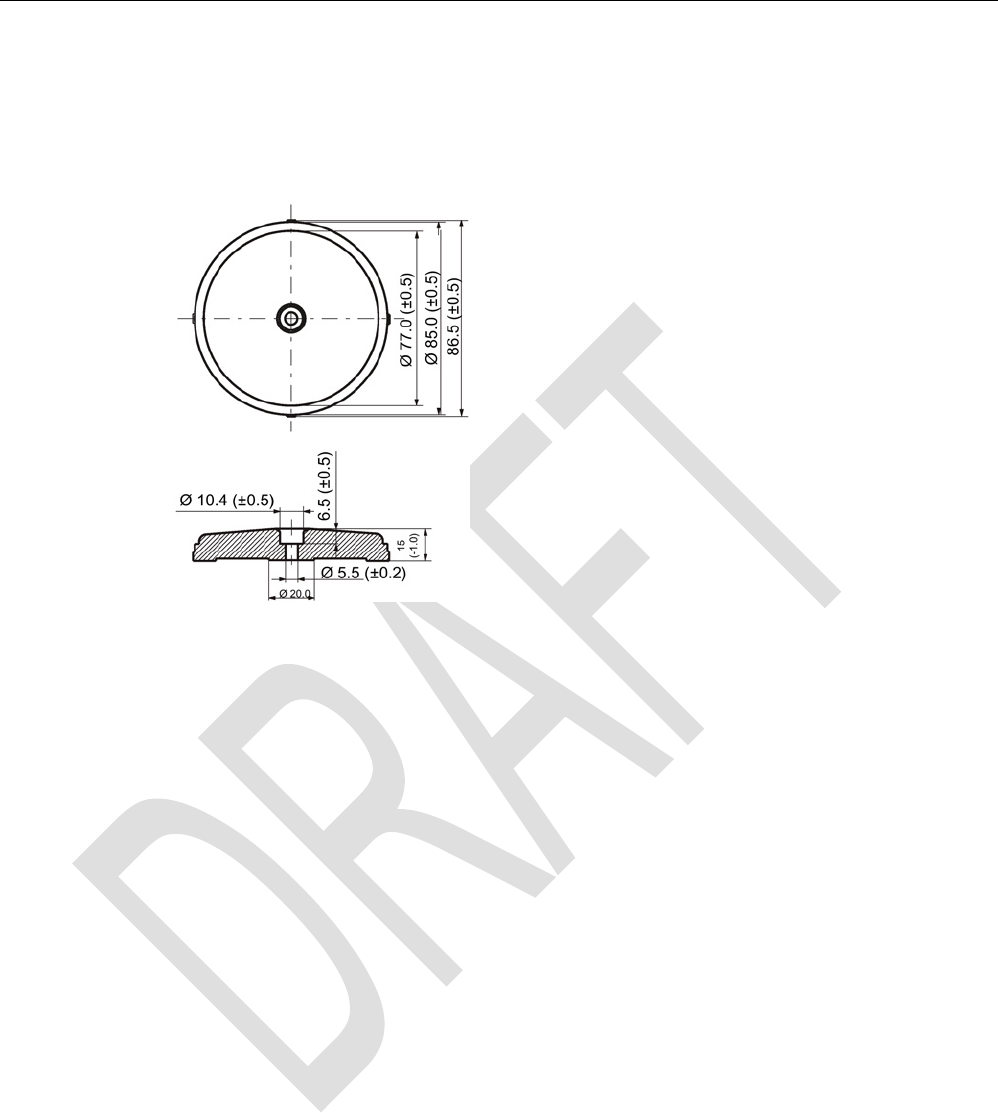
ISO transponder
8.7 MDS D139
SIMATIC RF300
282 System Manual, 07/2016, C79000-G8976-C345-0x
8.7.7
Dimension drawings
Dimensional drawing of MDS D139
Figure 8-16 Dimensional drawing of MDS D139
Dimensions in mm
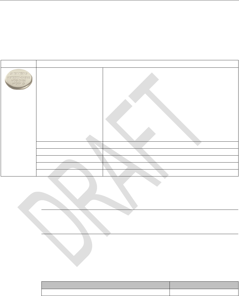
ISO transponder
8.8 MDS D160
SIMATIC RF300
System Manual, 07/2016, C79000-G8976-C345-0x 283
8.8
MDS D160
8.8.1
Characteristics
MDS D160
Characteristics
Area of application Thanks to its rugged packaging, the MDS D160 is a transponder that
can be used under extreme environmental conditions. It is washable,
heat-resistant and resistant to all chemicals generally used in the
laundry process.
Typical applications are, for example:
• Rented work clothing
• Hotel laundry
• Surgical textiles
• Hospital clothing
• Dirt collection mats
• Clothing for nursing homes/hostels
Memory size 112 bytes of EEPROM user memory
Write/read range
See section Field data of ISO transponders (MDS D) (Page 52).
Mounting on metal
Yes, with spacer
ISO standard
ISO 15693
Degree of protection
IP68/IPx9K
8.8.2
Information for RF300 compatibility
Note
Compatibility with SIMATIC RF300 depending on MLFB number
Only the MDS D160 with MLFB 6GT2600
-0AB10 is compatible with SIMATIC RF300.
8.8.3
Ordering data
Table 8- 18 Ordering data for MDS D160
Article number
MDS D160
6GT2600-0AB10
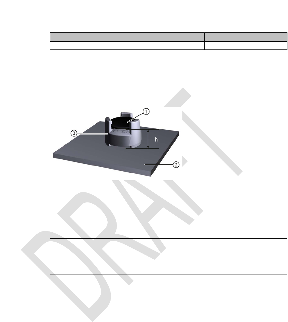
ISO transponder
8.8 MDS D160
SIMATIC RF300
284 System Manual, 07/2016, C79000-G8976-C345-0x
Table 8- 19 Ordering data for MDS D160 accessories
Article number
Spacer
6GT2690-0AG00
8.8.4
Mounting on metal
Mounting on metal
①
Transponder
②
Metal carrier
③
Spacer
h
≥ 10 mm
Figure 8-17 Mounting the MDS D160 on metal with spacer
Note
Going below the minimum distance (h)
If the minimum distance (h) is not observed, a reduction of the fie
ld data results.
In critical applications, it is recommended that a test is performed.
Flush-mounting
Flush-mounting of the MDS D160 in metal is not permitted!

ISO transponder
8.8 MDS D160
SIMATIC RF300
System Manual, 07/2016, C79000-G8976-C345-0x 285
8.8.5
Technical specifications
Table 8- 20 Technical specifications for the MDS D160
6GT2600-0AB10
Product type designation
SIMATIC MDS D160
Memory
Memory configuration
• UID • 8 bytes
• User memory • 112 bytes EEPROM
• OPT memory • 16 bytes (EEPROM)
Read cycles (at < 40 ℃)
> 10
14
Write cycles (at < 40 ℃)
> 10
6
Data retention time (at < 40 ℃)
> 10 years
Write/read distance (Sg) Dependent on the reader used, see section "Field
data of ISO transponders (MDS D) (Page 52)"
MTBF (Mean Time Between Failures)
228 years
Mechanical specifications
Housing
• Material
• Color
• PPS
• beige
Recommended distance to metal
≥ 10 mm
Power supply
Inductive, without battery
Permitted ambient conditions
Ambient temperature
• In operation, during write/read access • -25 … +85 °C
• In operation, outside write/read access • -40 … +175 °C
• from +125 ℃: for 1000 hours, 20% reduction
of the limit distance
• from +140 ℃: No processing possible
• at +175 ℃: 100 washing cycles tested
• at +220 ℃: Tested once for up to 30 seconds
• During transportation and storage • -25 to +100 ℃

ISO transponder
8.8 MDS D160
SIMATIC RF300
286 System Manual, 07/2016, C79000-G8976-C345-0x
6GT2600-0AB10
Mechanical strength
• Isostatic pressure • 300 bar for 5 min
• Axial pressure • 1000 N for 10 s
• Radial pressure • 1000 N for 10 s
Resistance to chemicals All chemicals normally used in the washing pro-
cess
MDS lifespan
At least 100 wash cycles
Degree of protection • IP68
24 hours, 2 bar, +20 °C
• IPx9K
Shock-resistant to IEC 68-2-27 40 g 1)
18 ms; 6 axes; 2000 repetitions/h
Vibration-resistant to IEC 68-2-6 10 g 1)
10 to 2000 Hz; 3 axes; 2.5 h
Torsion and bending load
Not permitted
Design, dimensions and weight
Dimensions (Ø x H)
16 x 3 mm
Weight
1.2 g
Type of mounting • Patched
• Sewn in
• Glued
1 The values for shock and vibration are maximum values and must not be applied continuously.
Note
Regeneration time between washing cycles
The regeneration time for the MDS D160 between washing cycles must be at least 24 ho
urs.
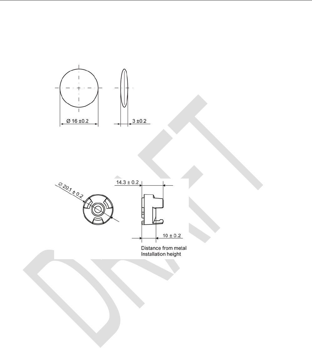
ISO transponder
8.8 MDS D160
SIMATIC RF300
System Manual, 07/2016, C79000-G8976-C345-0x 287
8.8.6
Dimension drawings
Dimensional drawing of MDS D160
Dimensions in mm
Figure 8-18 Dimensional drawing of MDS D160
Dimensional drawing of spacer
Dimensions in mm
Figure 8-19 Dimensional drawing of spacer
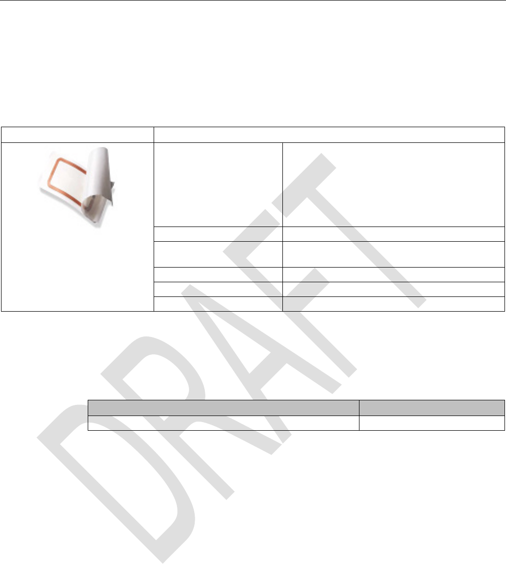
ISO transponder
8.9 MDS D165
SIMATIC RF300
288 System Manual, 07/2016, C79000-G8976-C345-0x
8.9
MDS D165
8.9.1
Features
MDS D165 (special version)
Characteristics
Area of application The design of the transponder (self-adhesive label)
permits a variety of designs, guaranteeing optimum
dimensioning for the widest variety of applications.
From simple identification such as electronic barcode
replacement/supplementation, through warehouse
and distribution logistics, right up to product identifi-
cation.
Memory size
112 bytes of EEPROM user memory
Write/read range See section Field data of ISO transponders (MDS D)
(Page 52).
Mounting on metal
Yes, with spacer
ISO standard
ISO 15693
Degree of protection
IP65
8.9.2
Ordering data
Table 8- 21 Ordering data for MDS D165
Article number
MDS D165 (special version ISO-CARD)
6GT2600-1AB00-0AX0
Type of delivery
Minimum order quantity: 1250 units (5 rolls with 250 units each)

ISO transponder
8.9 MDS D165
SIMATIC RF300
System Manual, 07/2016, C79000-G8976-C345-0x 289
8.9.3
Technical data
Table 8- 22 Technical specifications for MDS D165
6GT2600-1AB00-0AX0
Product type designation
SIMATIC MDS D165
Memory
Memory configuration
• UID • 8 bytes
• User memory • 112 bytes EEPROM
• OPT memory • 16 bytes (EEPROM)
Read cycles (at < 40 ℃)
> 10
14
Write cycles (at < 40 ℃)
> 10
6
Data retention time (at < 40 ℃)
> 10 years
Write/read distance (Sg) Depending on the reader used, see section "Field
data of ISO transponders (MDS D) (Page 52)"
MTBF (Mean Time Between Failures)
228 years
Mechanical specifications
Housing
• Material • Top • PET plastic (label
material)
• Inlay • PET plastic (carrier
material)
• Antenna • Aluminum
• Bottom • Double-sided trans-
fer adhesive on sili-
con paper
• Color • White
Recommended distance to metal
≥ 25 mm
Power supply
Inductive, without battery
Permitted ambient conditions
Ambient temperature
• In operation, during write/read access • -5 to +85 °C
• In operation, outside write/read access • -25 to +85 ℃
• During transportation and storage • +15 to +30 ℃
Can be stored for 2 years, determined by the
durability of the adhesive.
Degree of protection
IP65
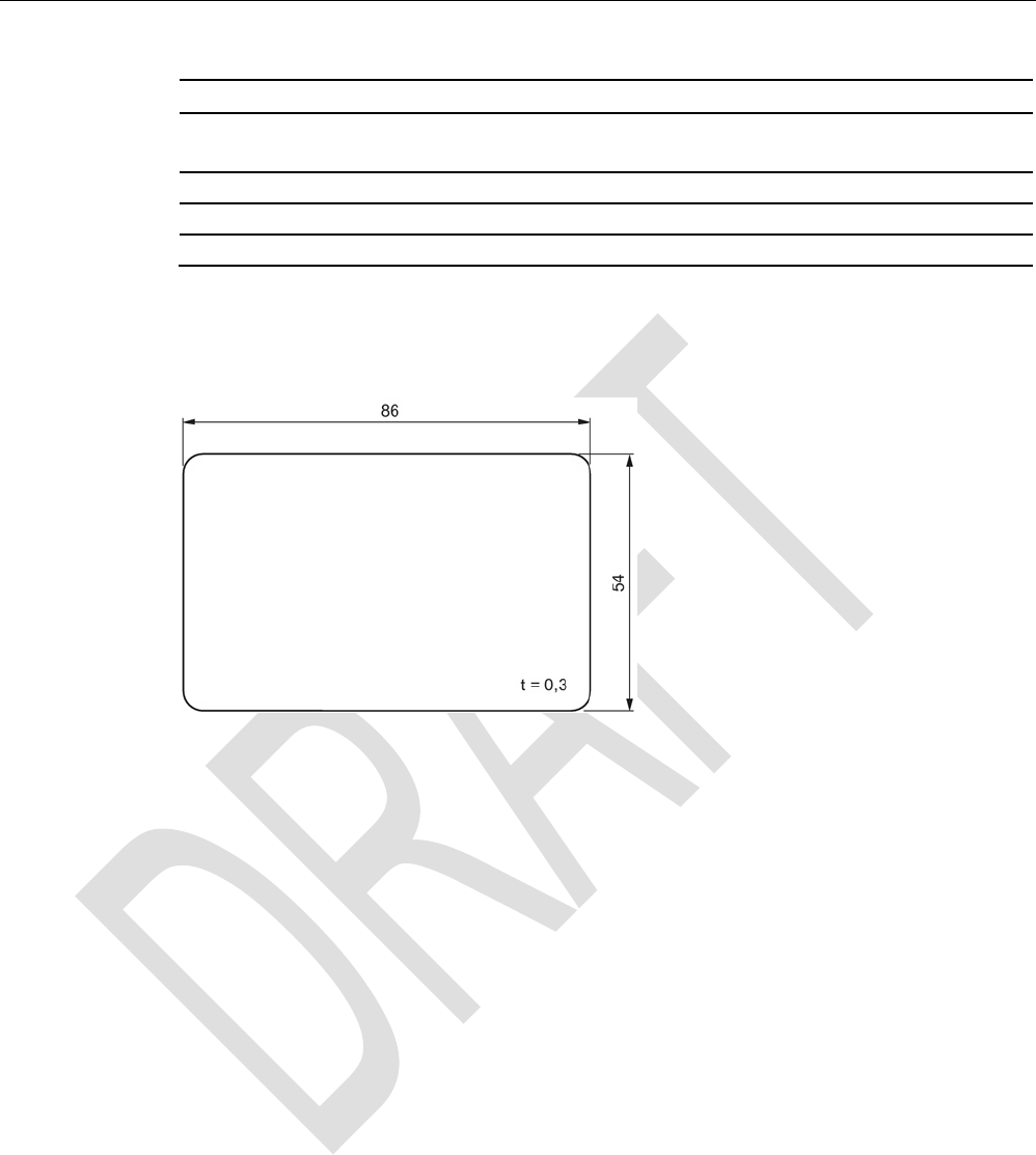
ISO transponder
8.9 MDS D165
SIMATIC RF300
290 System Manual, 07/2016, C79000-G8976-C345-0x
6GT2600-1AB00-0AX0
Design, dimensions and weight
Dimensions (L x W x H)
86 x 54 x 0.3 mm
Weight
1 g
Type of mounting
Glued with self-adhesive label
8.9.4
Dimension drawing
Dimensions in mm
Figure 8-20 Dimension drawing of MDS D165
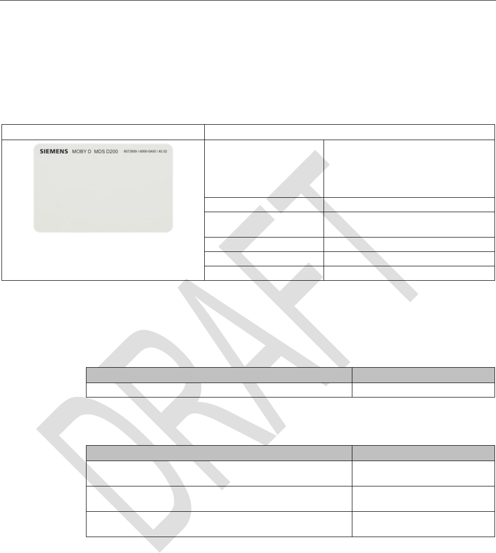
ISO transponder
8.10 MDS D200
SIMATIC RF300
System Manual, 07/2016, C79000-G8976-C345-0x 291
8.10
MDS D200
8.10.1
Features
MDS D200
Characteristics
Area of application From simple identification such as elec-
tronic barcode replace-
ment/supplementation, through
warehouse and distribution logistics, right
up to product identification.
Memory size
256 bytes of EEPROM user memory
Write/read range See section Field data of ISO transpond-
ers (MDS D) (Page 52).
Mounting on metal
Yes, with spacer
ISO standard
15693 with Tag-it HFI technology
Degree of protection
IP67
8.10.2
Ordering data
Table 8- 23 Ordering data for MDS D200
Article number
MDS D200 (special version ISO-CARD)
6GT2600-1AD00-0AX0
Table 8- 24 Ordering data for MDS D200 accessories
Article number
Spacer
(in conjunction with fixing pocket 6GT2190-0AB00)
6GT2190-0AA00
Fixing pocket
(in conjunction with spacer 6GT2190-0AA00)
6GT2190-0AB00
Fixing pocket
(not suitable for fixing directly onto metal)
6GT2390-0AA00
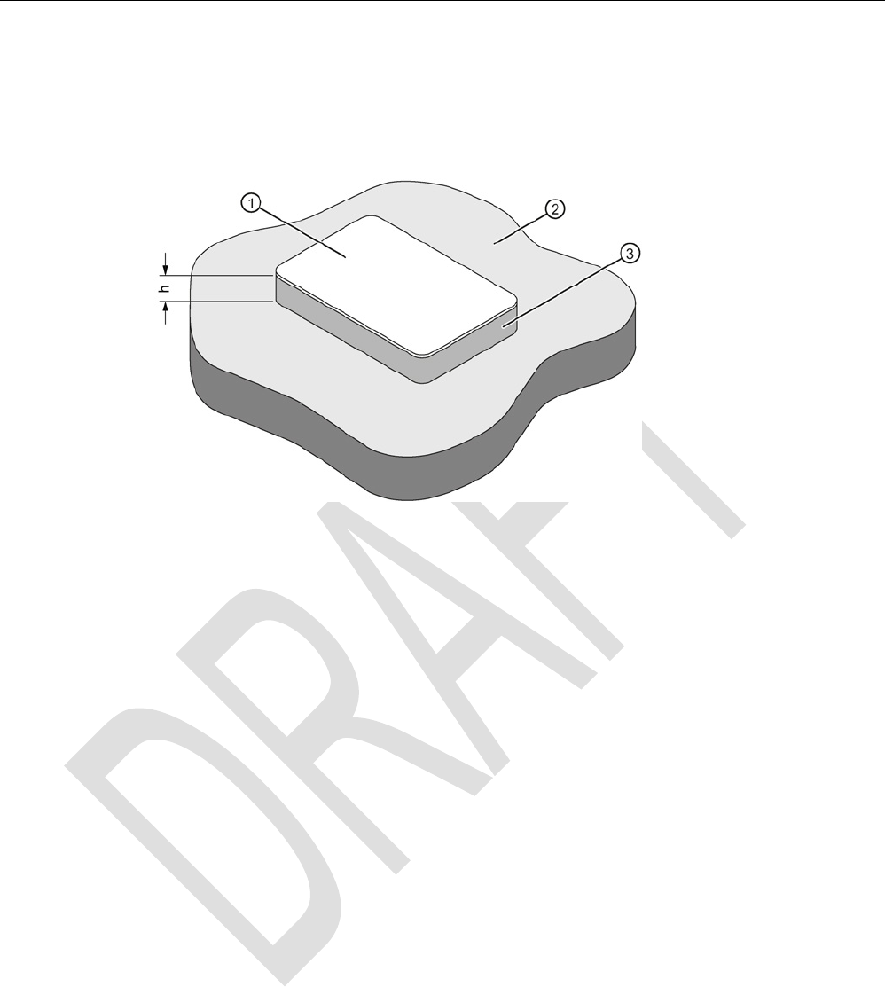
ISO transponder
8.10 MDS D200
SIMATIC RF300
292 System Manual, 07/2016, C79000-G8976-C345-0x
8.10.3
Mounting on metal
Mounting on metal
h
≥ 20 mm
①
Data memory
②
Metal
③
Non-metal
Figure 8-21 Mounting of the MDS D200 on metal with spacer
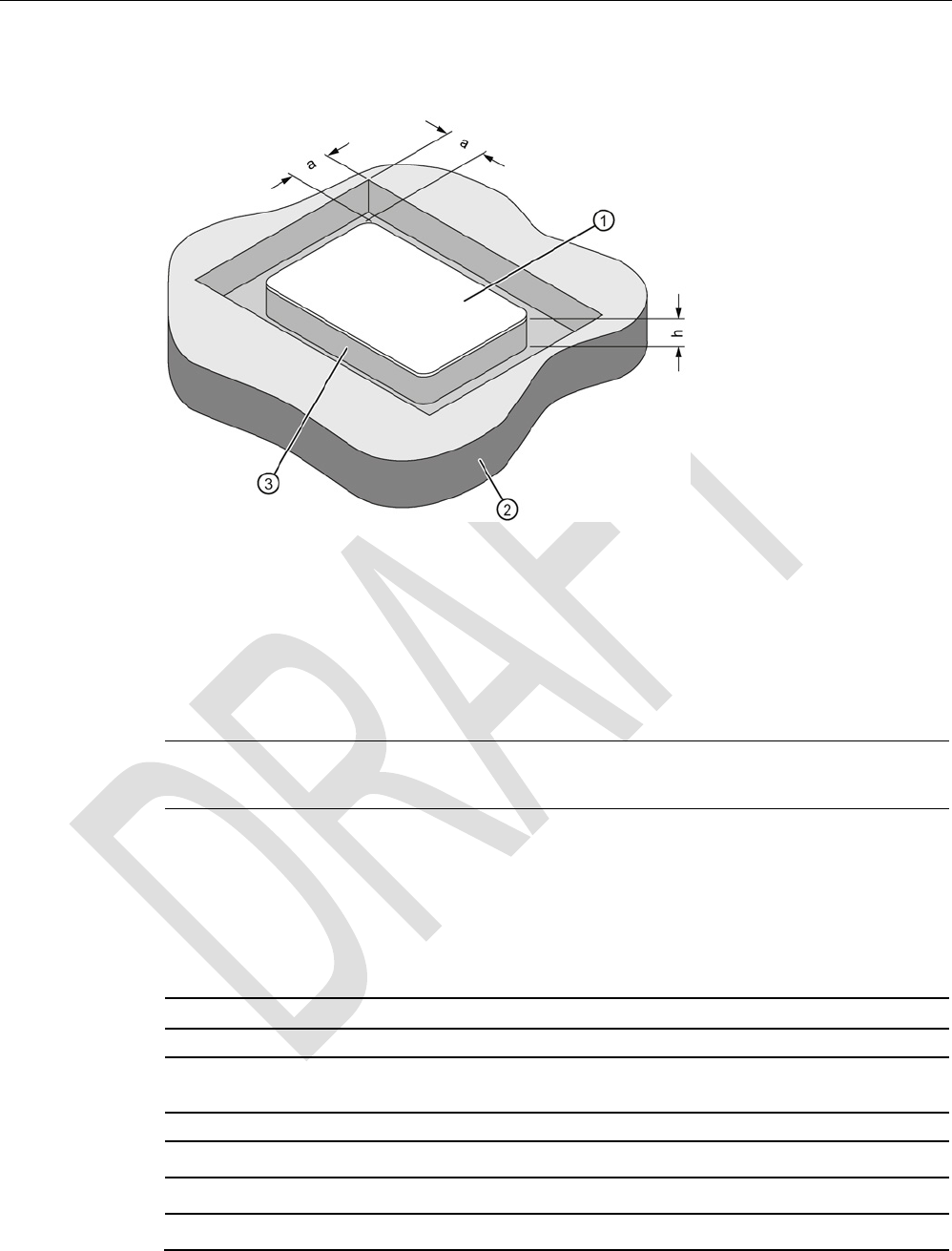
ISO transponder
8.10 MDS D200
SIMATIC RF300
System Manual, 07/2016, C79000-G8976-C345-0x 293
Flush-mounting
a
≥ 20 mm
h
≥ 20 mm
①
Data memory
②
Metal
③
Non-metal
Figure 8-22 Flush-mounting of MDS D200 in metal with spacer
Note
If the minimum guide values (h) are not observed, a reduction of the field data results.
8.10.4
Technical data
Table 8- 25 Technical specifications for MDS D200
6GT2600-1AD00-0AX0
Product type designation
SIMATIC MDS D200
Memory
Memory configuration
• UID • 8 bytes
• User memory • 256 bytes EEPROM
• OTP memory • 16 bytes (EEPROM)

ISO transponder
8.10 MDS D200
SIMATIC RF300
294 System Manual, 07/2016, C79000-G8976-C345-0x
6GT2600-1AD00-0AX0
Read cycles (at < 25 ℃)
> 10
14
Write cycles (at < 25 ℃)
> 10
6
Data retention time (at < 25 ℃)
> 10 years
Write/read distance (Sg) Dependent on the reader used, see section "Field
data of ISO transponders (MDS D) (Page 52)"
MTBF (Mean Time Between Failures)
228 years
Mechanical specifications
Housing
• Material • PET
• Color • White
Recommended distance to metal
≥ 20 mm
Power supply
Inductive, without battery
Permitted ambient conditions
Ambient temperature
• During operation • -20 to +60 ℃
• During transportation and storage • -20 to +60 ℃
Degree of protection to EN 60529
IP67
Shock-resistant to EN 60721-3-7 class 7M3
ISO 10373 / ISO 7810
1)
Vibration-resistant to EN 60721-3-7, class 7M3
ISO 10373 / ISO 7810
1)
Torsion and bending load
ISO 10373/ISO 7816-1
Design, dimensions and weight
Dimensions (L x W x H)
85 x 54 x 0.8 mm
Weight
5 g
Type of mounting • Fixing pocket
• Glued
1) The values for shock and vibration are maximum values and must not be applied continuously.
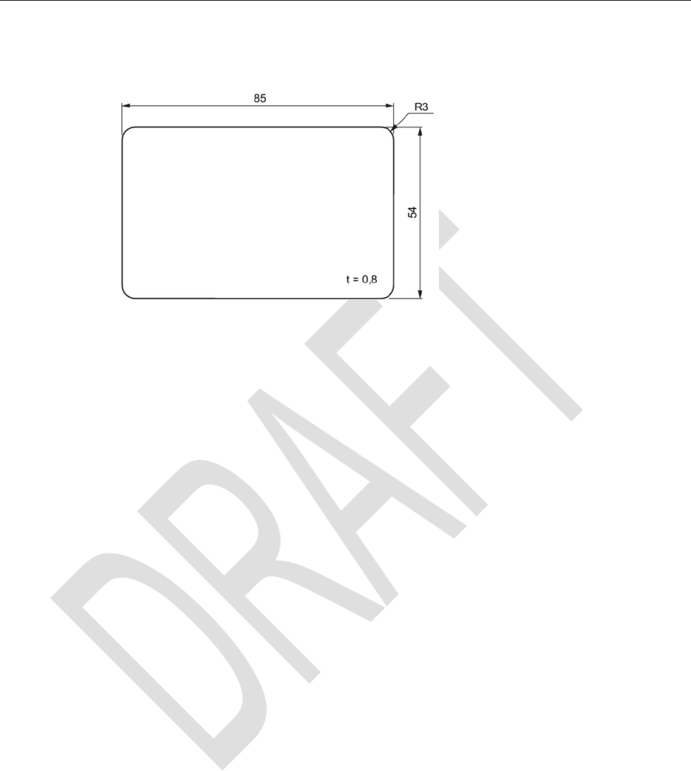
ISO transponder
8.10 MDS D200
SIMATIC RF300
System Manual, 07/2016, C79000-G8976-C345-0x 295
8.10.5
Dimension drawing
Dimensions in mm
Figure 8-23 Dimension drawing of MDS D200

ISO transponder
8.11 MDS D261
SIMATIC RF300
296 System Manual, 07/2016, C79000-G8976-C345-0x
8.11
MDS D261
8.11.1
Features
MDS D261
Characteristics
Area of application The design of the transponder (self-adhesive label)
permits a variety of designs, guaranteeing optimum
dimensioning for the widest variety of applications.
From simple identification such as electronic barcode
replacement/supplementation, through warehouse
and distribution logistics, right up to product identifi-
cation.
Memory size
256 bytes of EEPROM user memory
Write/read range See section Field data of ISO transponders (MDS D)
(Page 52).
Mounting on metal
Yes, with spacer
ISO standard
ISO 15693
Degree of protection
IP65
8.11.2
Ordering data
Table 8- 26 Ordering data for MDS D261
Article number
MDS D261
6GT2600-1AA00-0AX0
Type of delivery
Minimum order quantity: 1250 units (5 rolls with 250 units each)

ISO transponder
8.11 MDS D261
SIMATIC RF300
System Manual, 07/2016, C79000-G8976-C345-0x 297
8.11.3
Technical data
Table 8- 27 Technical specifications of MDS D261
6GT2600-1AA01-0AX0
Product type designation
SIMATIC MDS D261
Memory
Memory configuration
• UID • 8 bytes
• User memory • 256 bytes EEPROM
• OTP memory • 16 bytes (EEPROM)
Read cycles (at < 40 ℃)
> 10
14
Write cycles (at < 40 ℃)
> 10
6
Data retention time (at < 40 ℃)
> 10 years
Write/read distance (Sg) Dependent on the reader used, see section "Field
data of ISO transponders (MDS D) (Page 52)"
MTBF (Mean Time Between Failures)
228 years
Mechanical specifications
Housing
• Material • Top • PET plastic (label
material)
• Inlay • PET plastic (carrier
material)
• Antenna • Aluminum
• Bottom • Double-sided trans-
fer adhesive on sili-
con paper
• Color • White
Recommended distance to metal
≥ 25 mm
Power supply
Inductive, without battery
Permitted ambient conditions
Ambient temperature
• In operation, during write/read access • -5 to +85 °C
• In operation, outside write/read access • -25 to +85 ℃
• During transportation and storage • +15 to +30 ℃
Can be stored for 2 years, determined by the
durability of the adhesive
Degree of protection
IP65
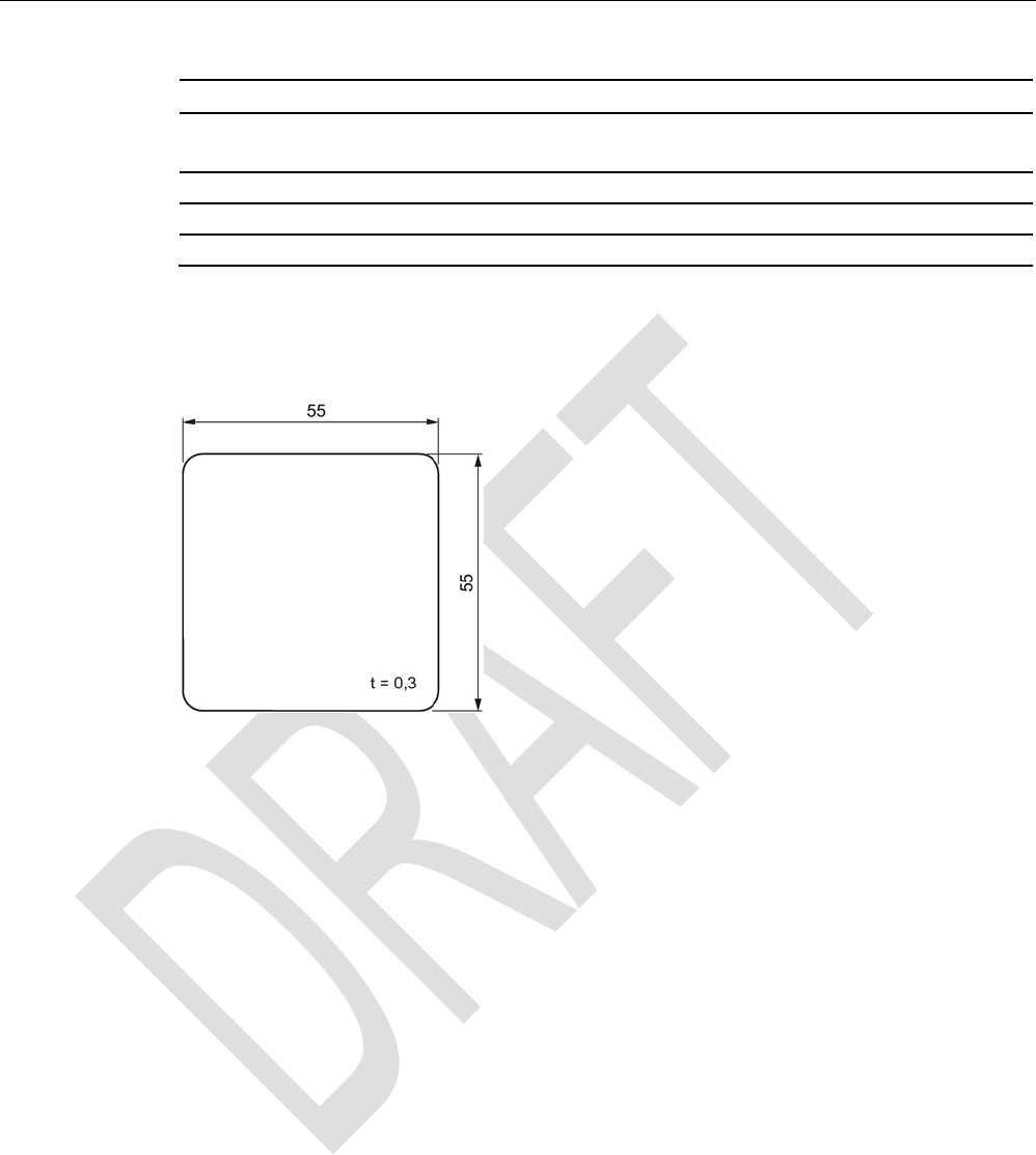
ISO transponder
8.11 MDS D261
SIMATIC RF300
298 System Manual, 07/2016, C79000-G8976-C345-0x
6GT2600-1AA01-0AX0
Design, dimensions and weight
Dimensions (L x W x H)
55 x 55 x 0.3 mm
Weight
1 g
Type of mounting
Glued with self-adhesive label
8.11.4
Dimension drawing
Dimensions in mm
Figure 8-24 Dimension drawing of MDS D261
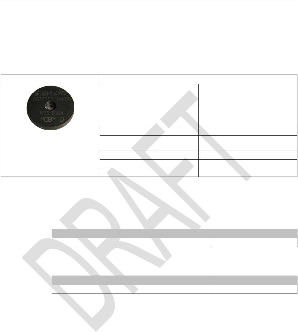
ISO transponder
8.12 MDS D324
SIMATIC RF300
System Manual, 07/2016, C79000-G8976-C345-0x 299
8.12
MDS D324
8.12.1
Characteristics
MDS D324
Characteristics
Area of application Production and distribution logistics
and product identification
Can also be used in harsh environ-
ments under extreme environmental
conditions (e.g. with hig
her temperature
load).
Memory size
992 bytes of EEPROM user memory
Write/read range See section "Field data of ISO tran-
sponders (MDS D) (Page 52)."
Mounting on metal
Yes, with spacer
ISO standard
ISO 15693
Degree of protection
IP67; IPx9K
8.12.2
Ordering data
Table 8- 28 Ordering data MDS D324
Article number
MDS D324
6GT2600-3AC00
Table 8- 29 Ordering data MDS D324 accessories
Article number
Spacer
6GT2690-0AK00

ISO transponder
8.12 MDS D324
SIMATIC RF300
300 System Manual, 07/2016, C79000-G8976-C345-0x
8.12.3
Mounting on metal
Mounting on metal
h
≥ 15 mm
Figure 8-25 Mounting the MDS D124/D324/D424/D524/E624 and RF320T on metal with spacer
Flush-mounting
h
≥ 15 mm
a
≥ 25 mm
Figure 8-26 Flush-mounting of the MDS D124/D324/D424/D524/E624 and RF320T in metal with
spacer

ISO transponder
8.12 MDS D324
SIMATIC RF300
System Manual, 07/2016, C79000-G8976-C345-0x 301
Note
Going below the distances
If the distances (a and h) are not observed, a reduction of the field data results. It
is possible
to mount the MDS with metal screws (M3 countersunk head screws). This has no tangible
impact on the range.
8.12.4
Technical specifications
Table 8- 30 Technical specifications of MDS D324
6GT2600-3AC00
Product type designation
SIMATIC MDS D324
Memory
Memory configuration
• UID • 8 bytes
• User memory • 992 bytes EEPROM
• OPT memory • 16 bytes (EEPROM)
Read cycles (at < 40 ℃)
> 10
14
Write cycles (at < 40 ℃)
> 10
6
Data retention time (at < 40 ℃)
> 10 years
Write/read distance (Sg) Dependent on the reader used, see section "Field
data of ISO transponders (MDS D) (Page 52)"
MTBF (Mean Time Between Failures)
228 years
Mechanical specifications
Housing
• Material • Epoxy resin
• Color • Black
Recommended distance to metal
≥ 15 mm
Power supply
Inductive, without battery
Permitted ambient conditions
Ambient temperature
• During operation • -25 to +125 ℃
• During transportation and storage • -40 to +140 ℃
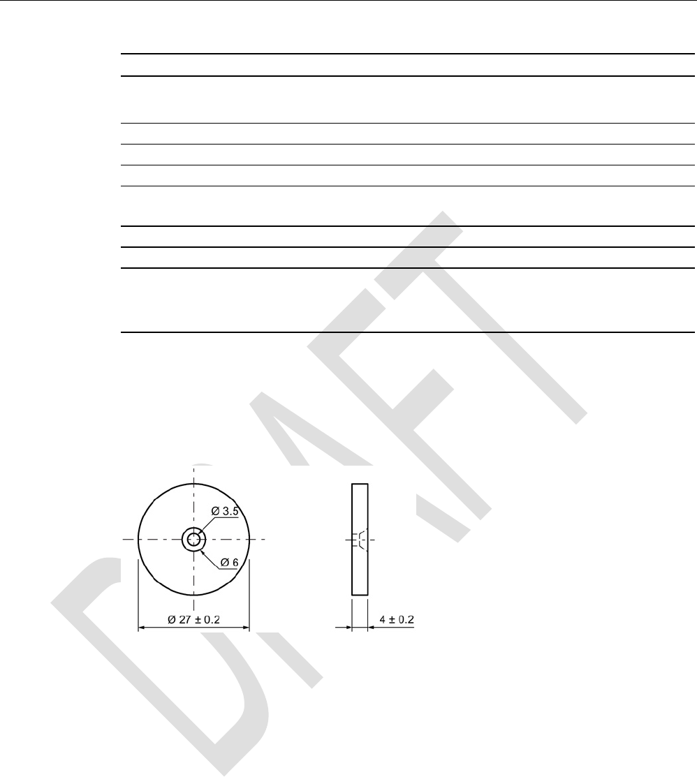
ISO transponder
8.12 MDS D324
SIMATIC RF300
302 System Manual, 07/2016, C79000-G8976-C345-0x
6GT2600-3AC00
Degree of protection to EN 60529 • IP67
• IPx9K
Shock-resistant to EN 60721-3-7 class 7M3
100 g
1)
Vibration-resistant to EN 60721-3-7, class 7M3
20 g
1)
Torsion and bending load
Not permitted
Design, dimensions and weight
Dimensions (Ø x H)
27 x 4 mm
Weight
5 g
Type of mounting • 1 x M3 screw 2)
≤ 1 Nm
• Glued
1)
The values for shock and vibration are maximum values and must not be applied continuously.
2 ) To prevent it loosening during operation, secure the screw with screw locking varnish.
8.12.5
Dimension drawing
Figure 8-27 Dimension drawing of MDS D324
All dimensions in mm