Siemens RF350R02 RFID Reader 13.56 MHz User Manual SIMATIC RF300
Siemens AG RFID Reader 13.56 MHz SIMATIC RF300
Siemens >
Contents
Users manual 2

SIMATIC RF300
System Manual, 07/2016, C79000-G8976-C345-0x 113
Readers
5
Features of the RF300 reader
The reader provides inductive communication with the transponders and serial connection to
the communications modules.
Communication between the transponder and reader takes place over inductive alternating
fields.
The transmittable data volume between reader and transponder depends on
● the speed at which the transponder moves through the transmission window of the
reader.
● the length of the transmission window,
● the transponder type used (RF300- / ISO 15693- (MDS D)/ ISO 14443 transponder (MDS
E)),
● the memory type (FRAM, EEPROM; with RF300 transponders).
ISO 15693 functionality
With all readers of the RF300 family, you can use ISO 15693 transponders. Note that the
readers for RF300, ISO 15963 or ISO 14443 operation must have parameters assigned. The
parameter assignment done with the aid of the RESET frame (INIT-Run).
For more detailed information on software parameter assignment refer to the manuals.
● Function manual "Ident profile and Ident blocks
(https://support.industry.siemens.com/cs/ww/en/view/106368029)",
● Product Information "FB 45 and FC 45 input parameters for RF300 and ISO transponders
(https://support.industry.siemens.com/cs/ww/en/view/33315697)",
● Function manual "FB 45 (https://support.industry.siemens.com/cs/ww/en/view/21738808)"
as of version "AS ≥ A3".

Readers
SIMATIC RF300
114 System Manual, 07/2016, C79000-G8976-C345-0x
ISO 14443 functionality
With all readers of the second generation of the RF300 family, you can use ISO 14443
transponders. The RF300 readers of the second generation therefore replace the MOBY E
readers SLG 72 and SLG 75. Note that the readers for RF300, ISO 15963 or ISO 14443
operation must have parameters assigned. The parameter assignment done with the aid of
the RESET frame (INIT-Run).
The following commands are supported in ISO 14443 operation of the readers:
● READ
● WRITE
● MDS-STATUS (mode 3)
● INIT
● REPEAT
Special ISO 14443 commands such as "INCREMENT", "DECREMENT" or "SET-VALUE"
are not supported.
Readers
5.1 SIMATIC RF310R
SIMATIC RF300
System Manual, 07/2016, C79000-G8976-C345-0x 115
5.1
SIMATIC RF310R
5.1.1
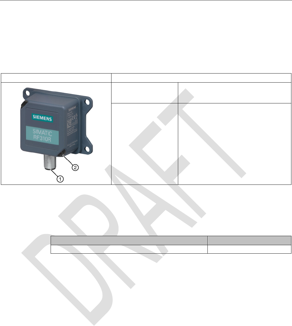
Features
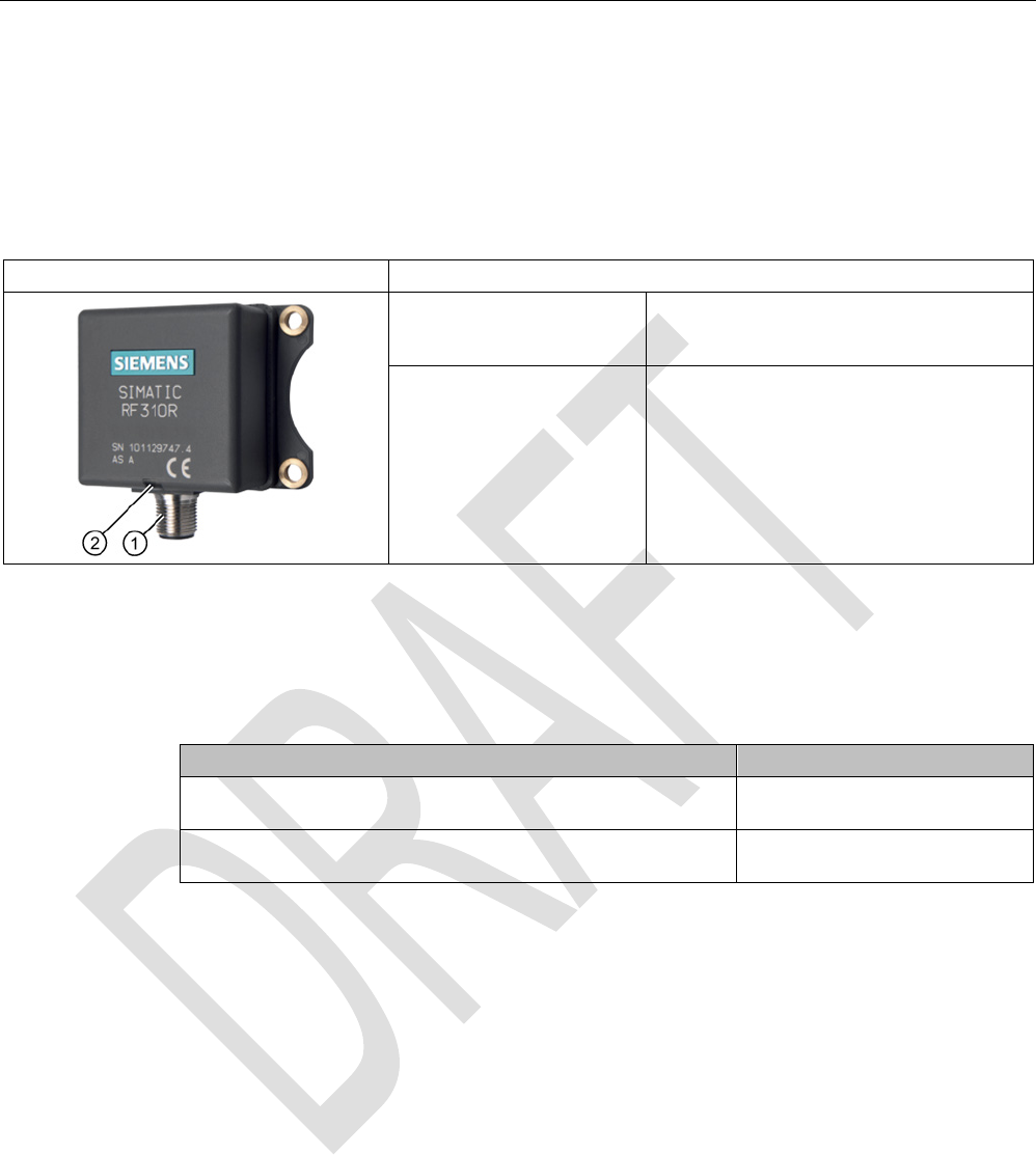
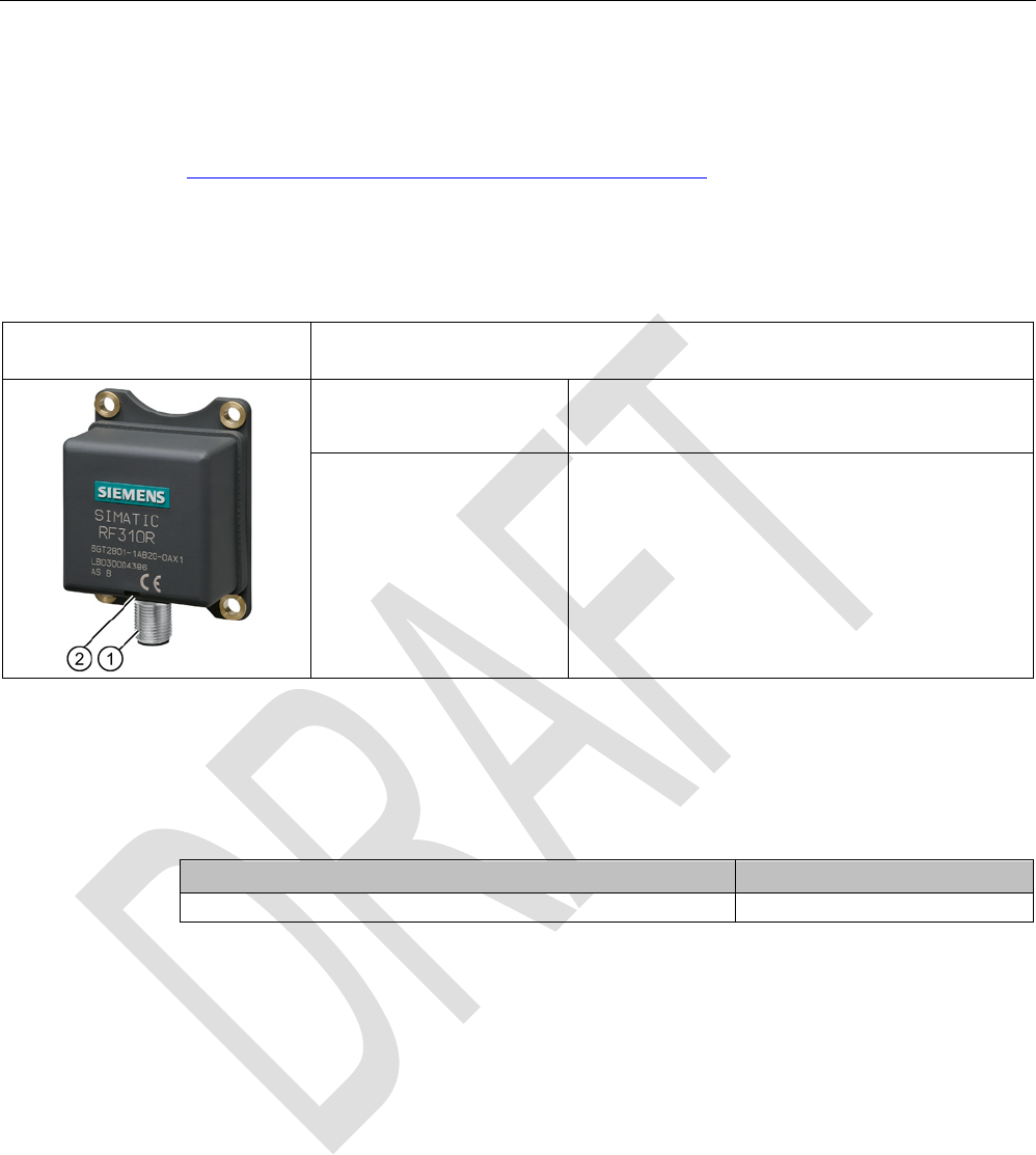
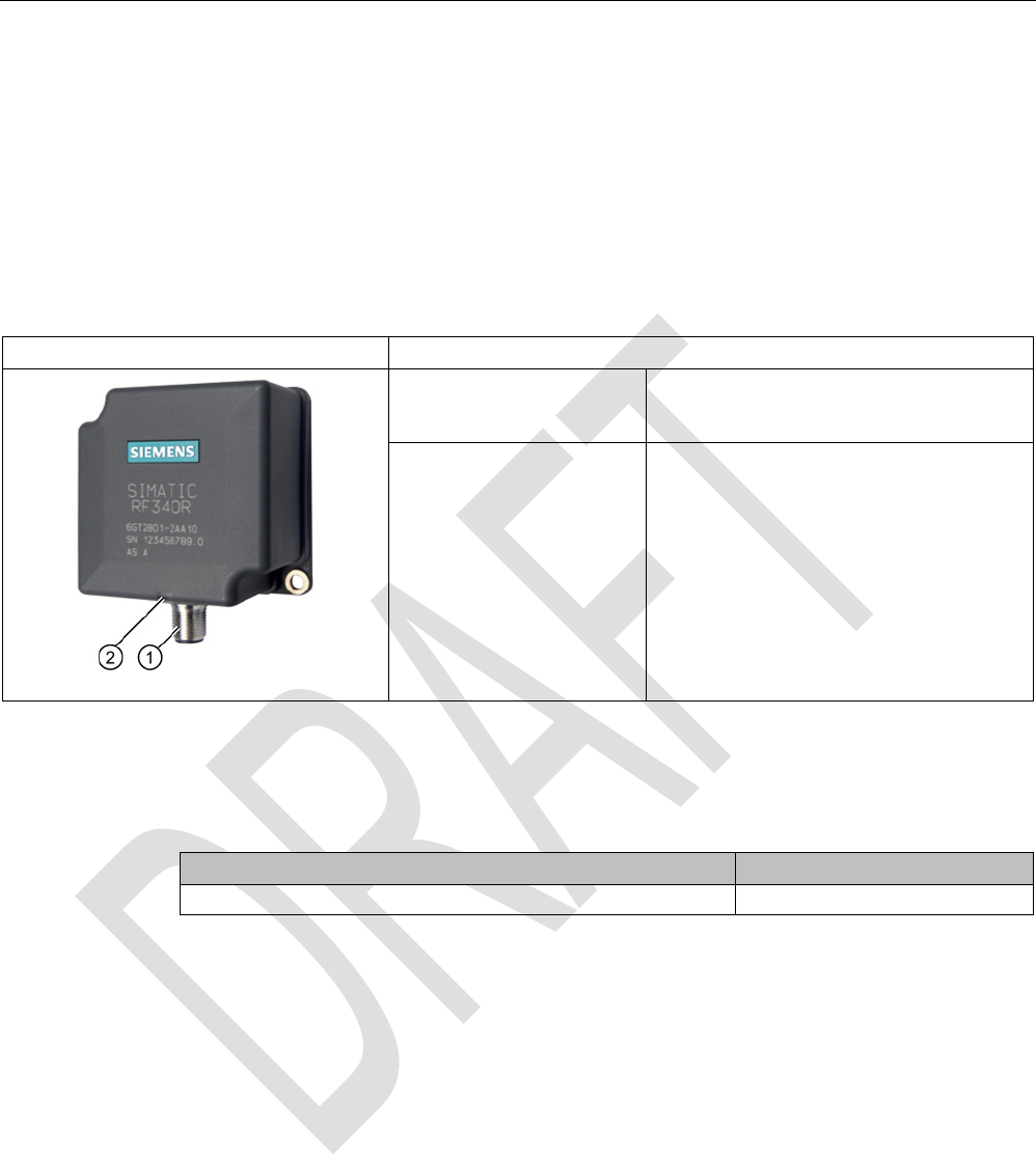
SIMATIC RF310R
Characteristics
Design ① RS-422 interface
②
Status display
Area of application Identification tasks on small assembly lines
in harsh industrial environments
5.1.2
RF310R ordering data
Table 5- 1 RF310R ordering data
Article number
RF310R with RS-422 interface (3964R)
horizontal base plate
6GT2801-1AB10
RF310R with RS-422 interface (3964R)
base plate turned through 90°
6GT2801-1AB10-0AX1
Readers
5.1 SIMATIC RF310R
SIMATIC RF300
116 System Manual, 07/2016, C79000-G8976-C345-0x
5.1.3
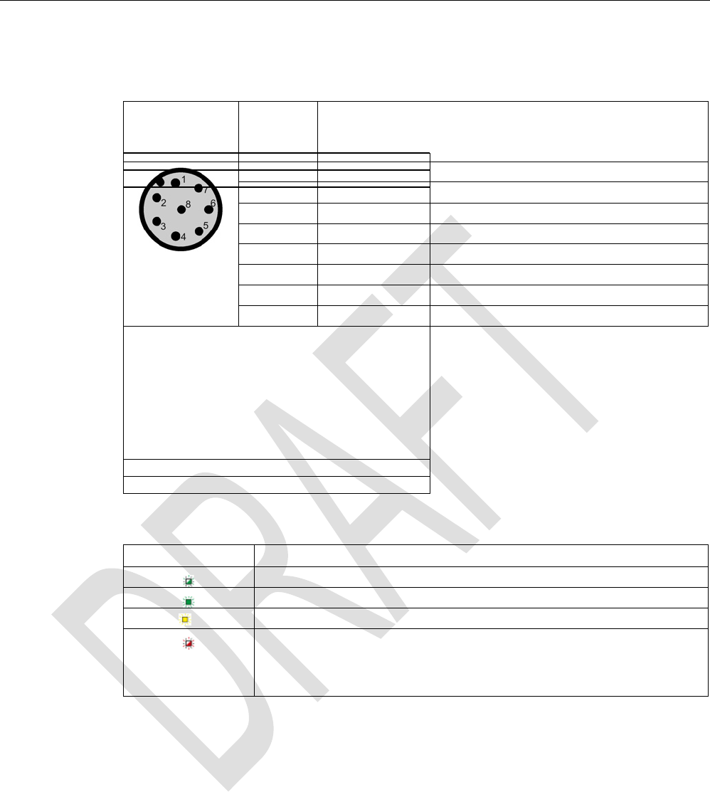
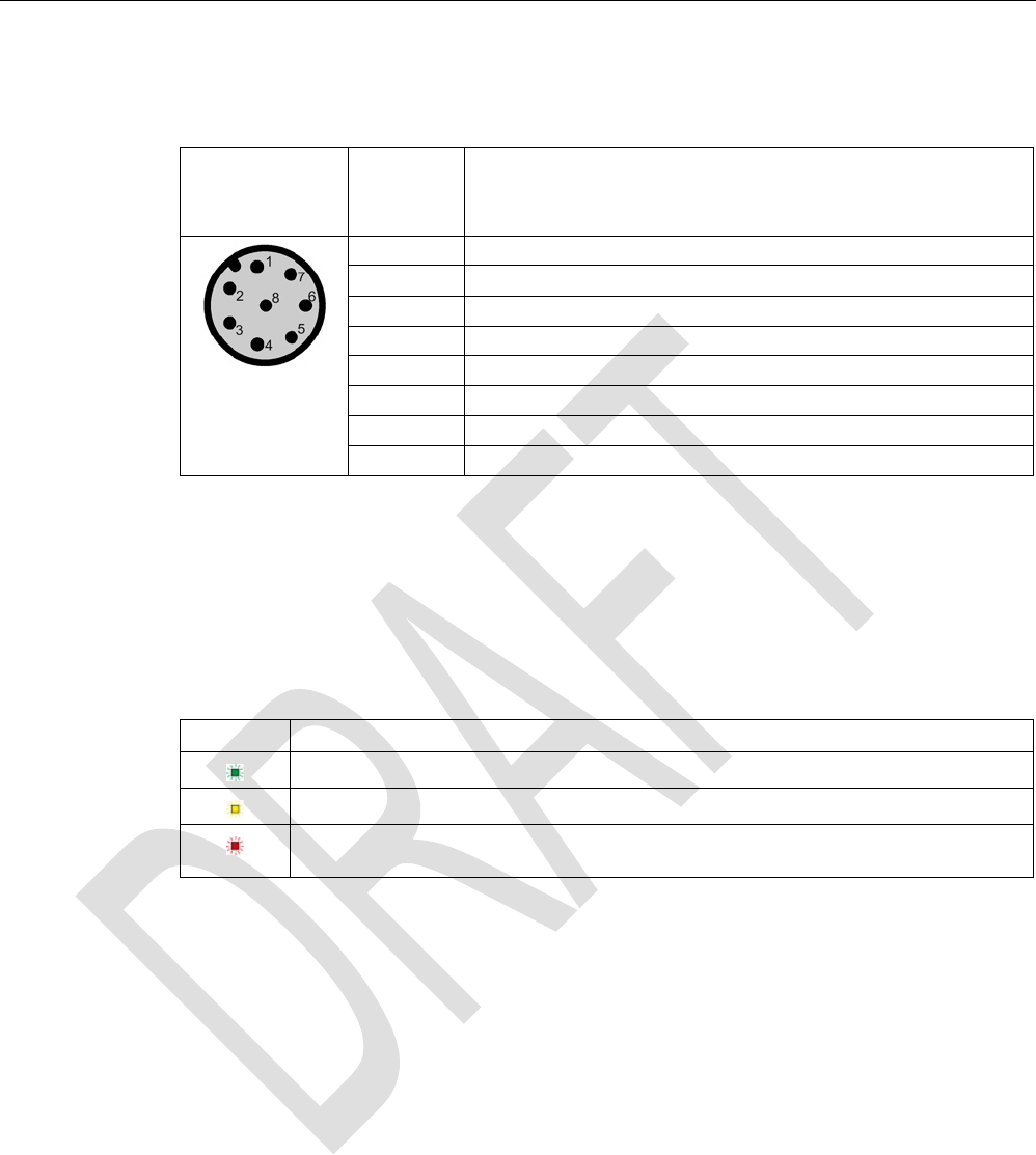
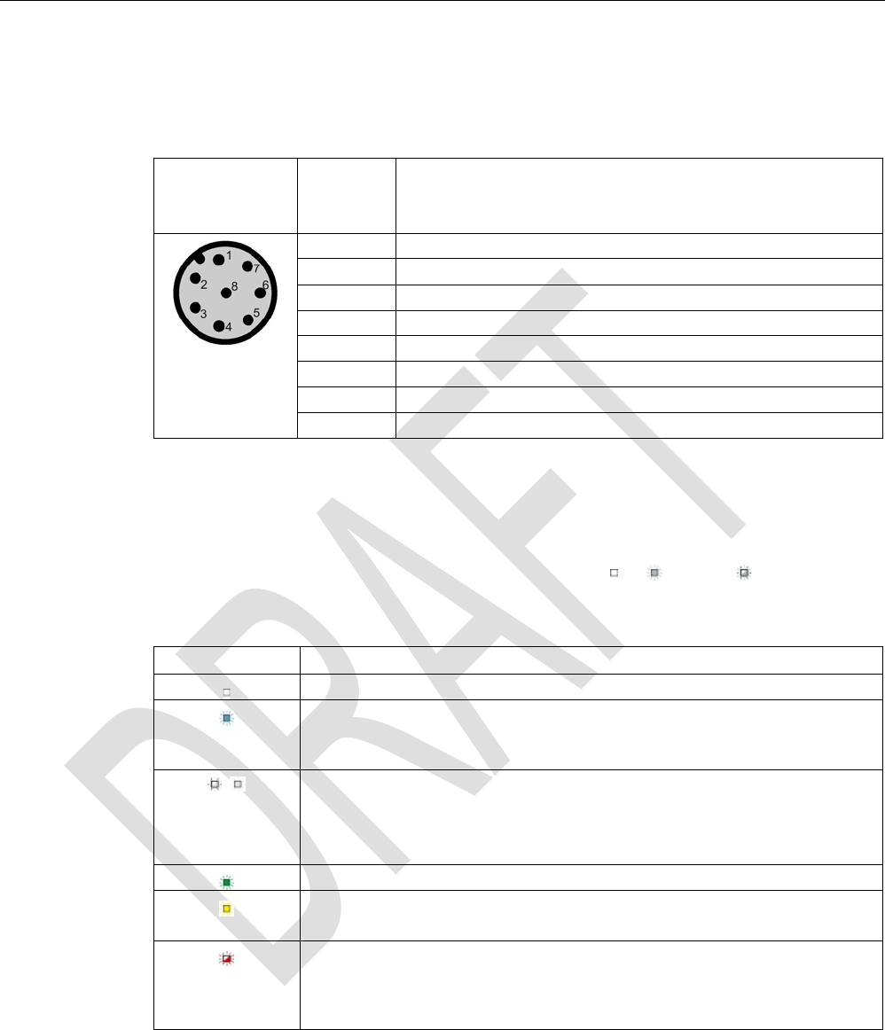
Pin assignment RF310R with RS-422 interface
Pin
Pin
Device end
8-pin M12
Assignment
1
+ 24 V
2 - Transmit
3
0 V
4
+ Transmit
5
+ Receive
6
- Receive
7
Unassigned
8
Earth (shield)
5.1.4
LED operating display
The operational statuses of the reader are displayed by the LEDs. The LED can adopt the
colors green, red or yellow and the statuses off
, on
, flashing
:
Table 5- 2 LED operating display on the reader
Color
Meaning
Operating voltage present, reader not initialized or antenna switched off
Operating voltage present, reader initialized and antenna switched on
1)
Transponder present
Error has occurred, the type of flashing corresponds to the error code in the
table in the section Error codes. The optical error display is only reset if the
corresponding reset parameter ("option_1", see FC 45 / FB 45 documentation,
section Input parameters) is set.
1) Only in the "with presence" mode.
5.1.5
Ensuring reliable data exchange
The "center point" of the transponder must be situated within the transmission window.
Readers
5.1 SIMATIC RF310R
SIMATIC RF300
System Manual, 07/2016, C79000-G8976-C345-0x 117
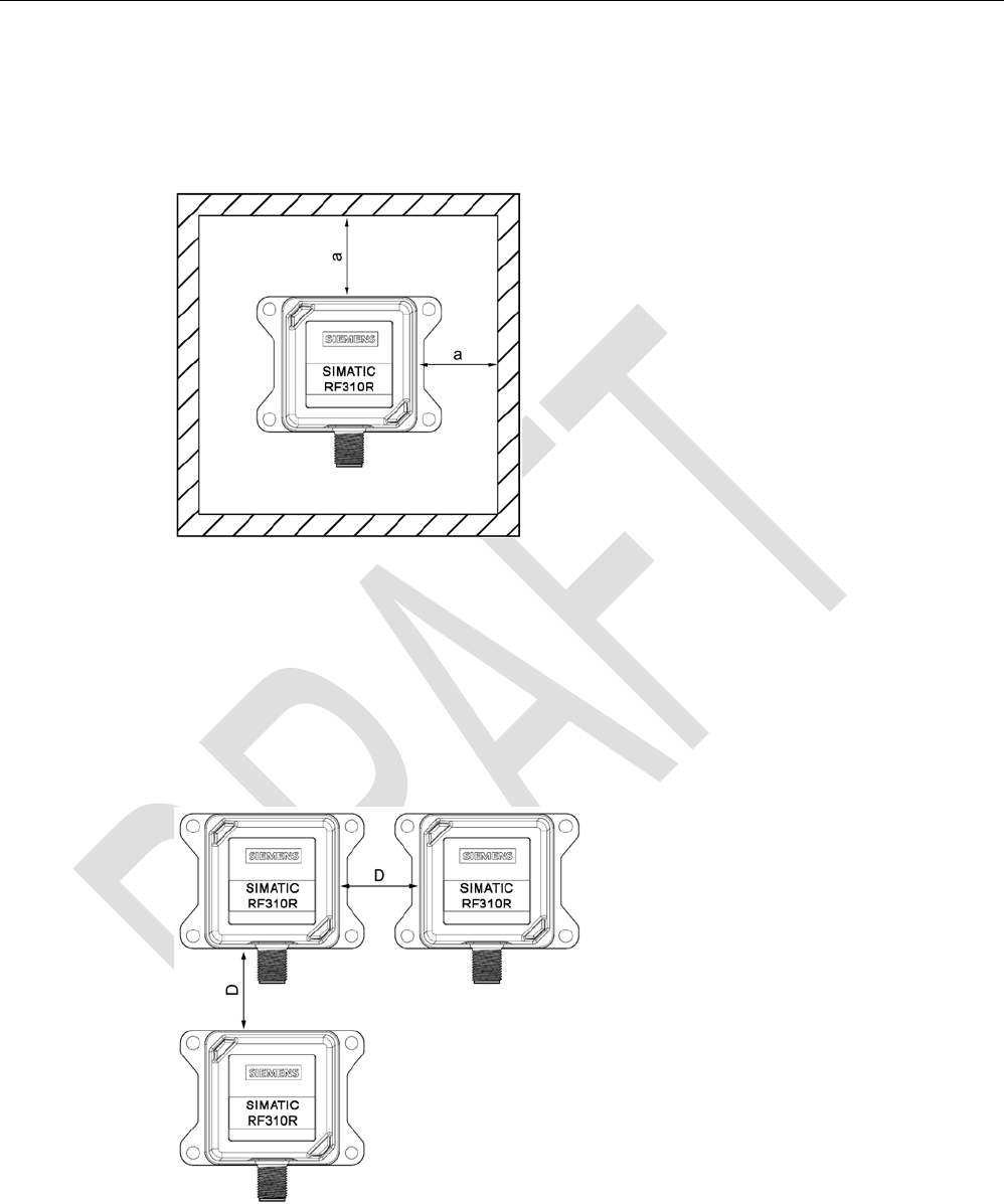
5.1.6
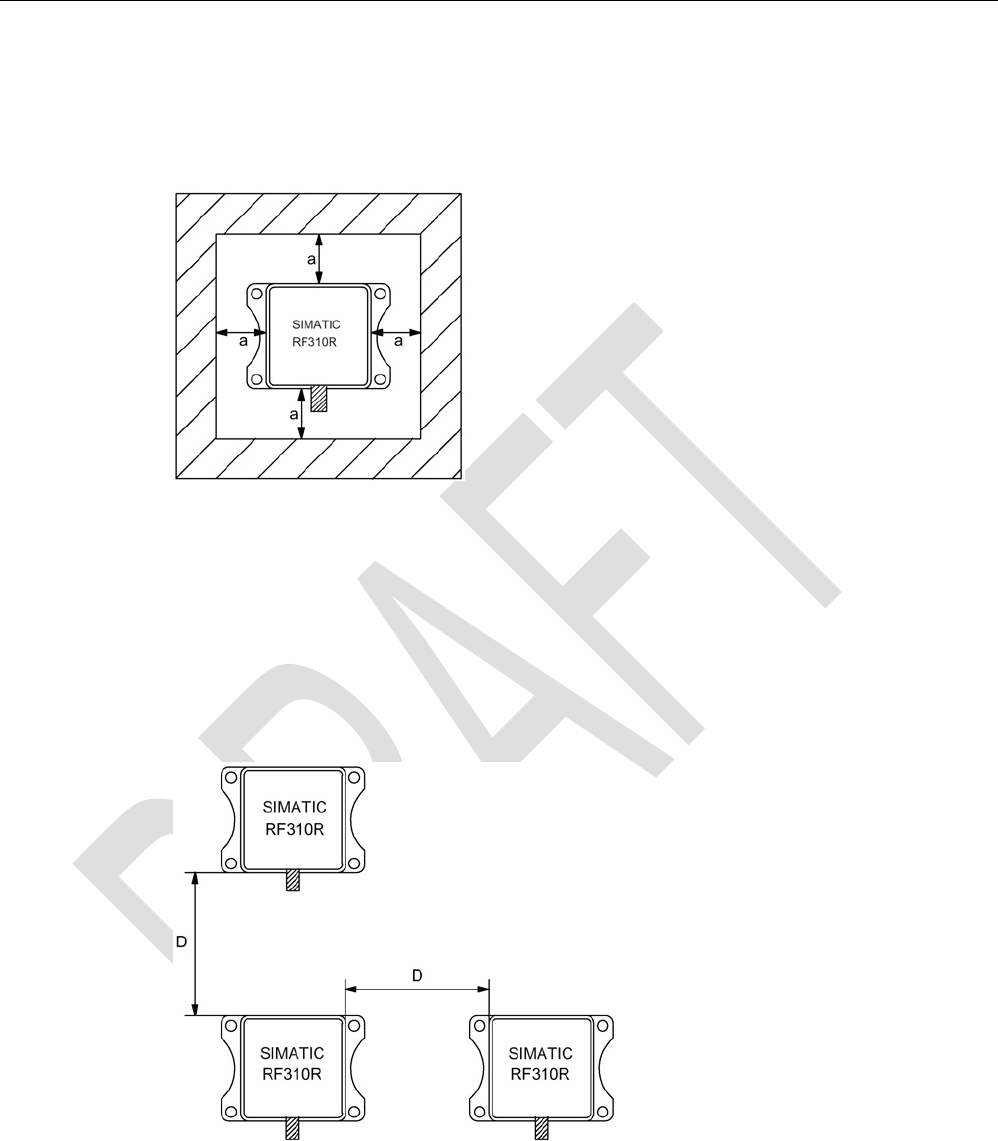
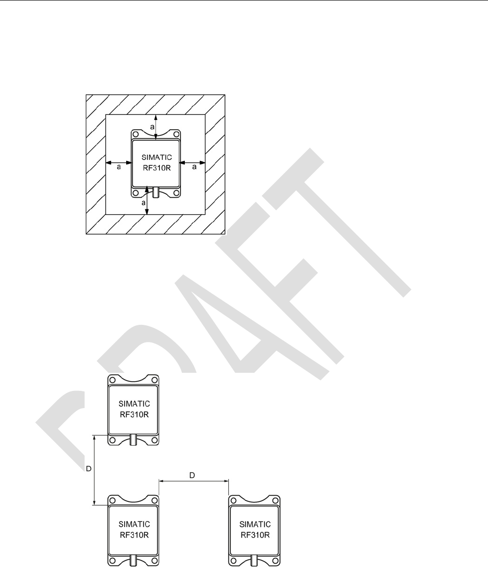
Metal-free area
The RF310R can be flush-mounted in metal. Please allow for a possible reduction in the field
data values.
Figure 5-1 Metal-free area for RF310R
To avoid any impact on the field data, the distance a should be ≥ 20 mm.
5.1.7
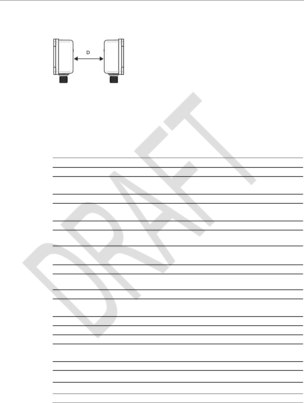
Minimum distance between RF310R readers
RF310R side by side
D
≥ 150 mm (with 2 readers)
D
≥ 200 mm (with more than 2 readers)
Figure 5-2 Minimum distance between RF310R readers
Readers
5.1 SIMATIC RF310R
SIMATIC RF300
118 System Manual, 07/2016, C79000-G8976-C345-0x
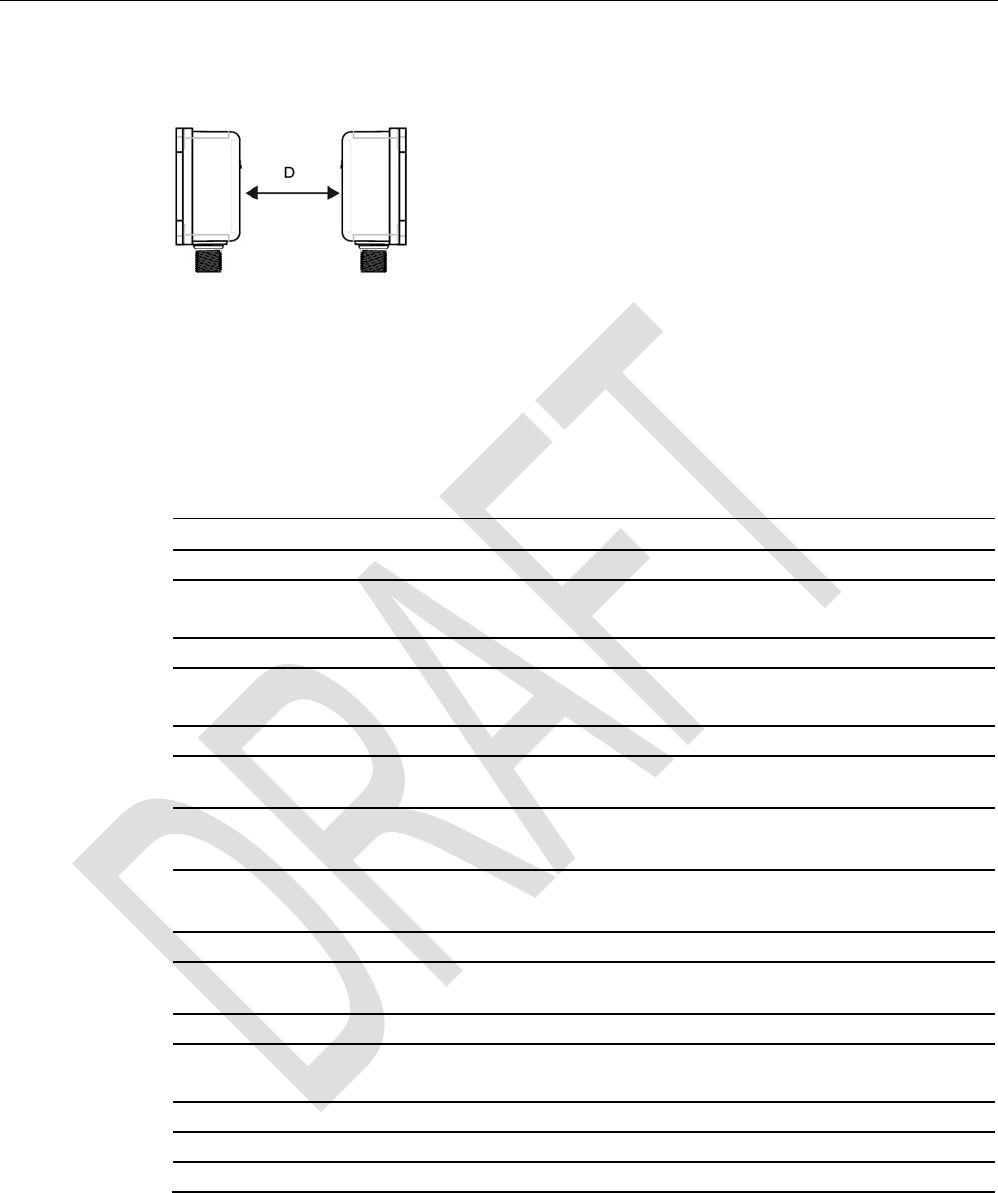
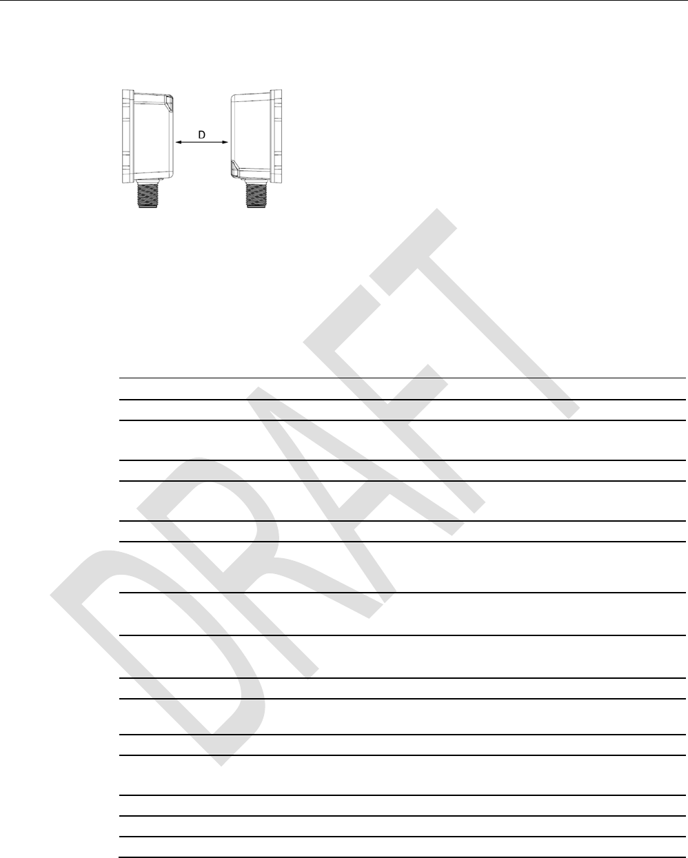
RF310R face-of-face
D
≥ 300 mm
Figure 5-3 Face-of-face distance between two RF310Rs
5.1.8
Technical specifications
Table 5- 3 Technical specifications of the RF310R reader with RS-422 interface
6GT2801-1AB10
Product type designation
SIMATIC RF310R
Radio frequencies
Operating frequency, rated value
13.56 MHz
Electrical data
Maximum range
60 mm
Maximum data transmission speed
reader ↔ transponder
RF300 transponder ISO transponder
• Read • approx. 8000
bytes/s
• approx. 1500
bytes/s
• Write • approx. 8000
bytes/s
• approx. 1500
bytes/s
Transmission speed
19.2, 57.6, 115.2 kBd
Read/write distances of the reader See section "Field data for transponders, readers
and antennas (Page 48)."
MTBF (Mean Time Between Failures)
170 years
Interfaces
Electrical connector design
M12, 8-pin
Standard for interfaces for communication
RS-422
Antenna
integrated

Readers
5.1 SIMATIC RF310R
SIMATIC RF300
System Manual, 07/2016, C79000-G8976-C345-0x 119
6GT2801-1AB10
Mechanical specifications
Housing
• Material • Plastic PA 12
• Color • Anthracite
Recommended distance to metal
0 mm
Supply voltage, current consumption, power loss
Supply voltage
24 VDC
Typical current consumption
50 mA
Permitted ambient conditions
Ambient temperature
• During operation • -25 to +70 ℃
• During transportation and storage • -40 to +85 ℃
Degree of protection to EN 60529
IP67
Shock-resistant to EN 60721-3-7, Class 7 M3
50 g
Vibration-resistant to EN 60721-3-7, Class 7 M3
20 g
Torsion and bending load
Not permitted
Design, dimensions and weight
Dimensions (L x W x H)
75 x 55 x 30 mm
Weight
200 g
Type of mounting 4 x M5 screw;
1.5 Nm
Cable length for RS-422 interface, maximum
1000 m
LED display design 3-color LED
Standards, specifications, approvals
Proof of suitability Radio to R&TTE directives EN 300330,
EN 301489, CE, FCC, UL/CSA

Readers
5.1 SIMATIC RF310R
SIMATIC RF300
120 System Manual, 07/2016, C79000-G8976-C345-0x
5.1.9
Approvals
FCC information
Siemens SIMATIC RF310R (MLFB 6GT2801-1AB10); FCC ID NXW-RF310R
This device complies with part 15 of the FCC rules. Operation is subject to the following two
conditions:
(1) This device may not cause harmful interference, and
(2) this device must accept any interference received, including interference that may cause
undesired operation.
Caution
Any changes or modifications not expressly approved by the party responsible for
compliance could void the user's authority to operate the equipment.
Note
This equipment has been tested and found to comply with the limits for a Class A digital
device, pursuant to part 15 of the FCC Rules.
These limits are designed to provide reasonable protection against harmful interference
when the equipment is operated in a commercial environment. This equipment generates,
uses, and can radiate radio frequency energy and, if not installed and used in accordance
with the instruction manual, may cause harmful interference to radio communications.
Operation of this equipment in a residential area is likely to cause harmful interference in
which case the user will be required to correct the interference at his own expense.
IC information
This device complies with Industry Canada licence-exempt RSS standard(s). Operation is
subject to the following two conditions:
(1) This device may not cause interference, and
(2) this device must accept any interference, including interference that may cause
undesired operation of the device.
Le présent appareil est conforme aux CNR d`Industrie Canada applicables aux appareils
radio exempts de licence. L`exploitation est autorisée aux deux conditions suivantes :
(1) L`appareil ne doit pas produire de brouillage, et
(2) l'utilisateur de l`appareil doit accepter tout brouillage radioélectrique subi, même si le
brouillage est susceptible d`en compromettre le fonctionnement.
Readers
5.1 SIMATIC RF310R
SIMATIC RF300
System Manual, 07/2016, C79000-G8976-C345-0x 121
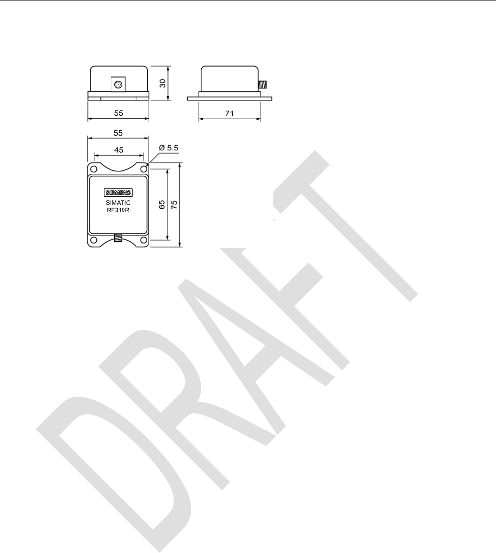
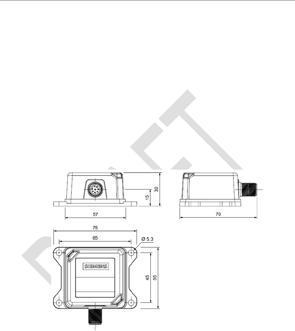
5.1.10
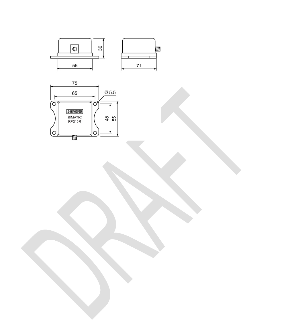
Dimension drawing
Figure 5-4 Dimension drawing for RF310R
Dimensions in mm
Readers
5.2 SIMATIC RF310R with Scanmode
SIMATIC RF300
122 System Manual, 07/2016, C79000-G8976-C345-0x
5.2
SIMATIC RF310R with Scanmode
You will find detailed information on the SIMATIC RF310R with Scanmode on the Internet
(https://support.industry.siemens.com/cs/ww/en/ps/15034).
5.2.1
Features
SIMATIC RF310R special version
Scanmode
Characteristics
Design ① RS-422 interface
②
Status display
Area of application Identification tasks on small assembly lines in harsh
industrial environments
5.2.2
Ordering data for RF310R with Scanmode
Table 5- 4 Ordering data RF310R Scanmode
Article number
RF310R special version Scanmode with RS-422 interface 6GT2801-1AB20-0AX1
Readers
5.2 SIMATIC RF310R with Scanmode
SIMATIC RF300
System Manual, 07/2016, C79000-G8976-C345-0x 123
5.2.3
Pin assignment RF310R special version Scanmode RS-422 interface
Pin
Pin
Device end
8-pin M12
Assignment
1
+ 24 V
2 - Transmit
3
0 V
4
+ Transmit
5
+ Receive
6
- Receive
7
Unassigned
8
Earth (shield)
5.2.4
LED operating display
The operational statuses of the reader are displayed by the LEDs. The LED can adopt the
colors green, red or yellow and the statuses off , on , flashing :
Table 5- 5 LED operating display on the reader
Color
Meaning
Operating voltage present, reader ready for operation
Transponder present
Red LED for error display is activated permanently if correct operation of the reader
cannot be guaranteed (e. g. faulty start, checksum error during operation).
5.2.5
Ensuring reliable data exchange
The "center point" of the transponder must be situated within the transmission window.
Readers
5.2 SIMATIC RF310R with Scanmode
SIMATIC RF300
124 System Manual, 07/2016, C79000-G8976-C345-0x
5.2.6
Metal-free area
The RF310R special version can be flush-mounted in metal. Please allow for a possible
reduction in the field data values.
Figure 5-5 Metal-free area for RF310R special version
To avoid any impact on the field data, the distance a should be ≥ 20 mm.
5.2.7
Minimum distance between several readers
RF310R special version side by side
D
≥ 150 mm (with 2 readers)
D
≥ 200 mm (with more than 2 readers)
Figure 5-6 Minimum distance between RF310R readers
Readers
5.2 SIMATIC RF310R with Scanmode
SIMATIC RF300
System Manual, 07/2016, C79000-G8976-C345-0x 125
RF310R special version face-to-face
D
≥ 300 mm
Figure 5-7 Face-to-face distance between two RF310R special version
5.2.8
Technical specifications
Table 5- 6 Technical specifications of the RF310R reader with Scanmode
6GT2801-1AB20-0AX1
Product type designation
SIMATIC RF310R Scanmode
Radio frequencies
Operating frequency, rated value
13.56 MHz
Electrical data
Maximum range
60 mm
Maximum data transmission speed
reader ↔ transponder
RF300 transponder ISO transponder
• Read • approx. 8000
bytes/s
• approx. 1500
bytes/s
Transmission speed
9.6, 19.2, 38.4, 57.6, 115.2 kBd
Read/write distances of the reader See section "Field data for transponders, readers
and antennas (Page 48)."
MTBF (Mean Time Between Failures)
170 years
Interfaces
Electrical connector design
M12, 8-pin
Standard for interfaces for communication
RS-422 (Scanmode)
Antenna
integrated
Mechanical specifications
Housing
• Material • Plastic PA 12
• Color • Anthracite
Recommended distance to metal 0 mm

Readers
5.2 SIMATIC RF310R with Scanmode
SIMATIC RF300
126 System Manual, 07/2016, C79000-G8976-C345-0x
6GT2801-1AB20-0AX1
Supply voltage, current consumption, power loss
Supply voltage
24 VDC
Typical current consumption
50 mA
Permitted ambient conditions
Ambient temperature
• During operation • -25 to +70 ℃
• During transportation and storage • -40 to +85 ℃
Degree of protection to EN 60529
IP67
Shock-resistant to EN 60721-3-7, Class 7 M3
50 g
Vibration-resistant to EN 60721-3-7, Class 7 M3
20 g
Torsion and bending load
Not permitted
Design, dimensions and weight
Dimensions (L x W x H)
75 x 55 x 30 mm
Weight
170 g
Type of mounting 4 x M5 screws;
1.5 Nm
Cable length for RS-422 interface, maximum
1000 m
LED display design
3-color LED
Standards, specifications, approvals
Proof of suitability Radio to R&TTE directives EN 300330,
EN 301489, CE, FCC, UL/CSA

Readers
5.2 SIMATIC RF310R with Scanmode
SIMATIC RF300
System Manual, 07/2016, C79000-G8976-C345-0x 127
5.2.9
Approvals
FCC information
Siemens SIMATIC RF310R (MLFB 6GT2801-1AB20-0AX1); FCC ID NXW-RF310R
This device complies with part 15 of the FCC rules. Operation is subject to the following two
conditions:
(1) This device may not cause harmful interference, and
(2) this device must accept any interference received, including interference that may cause
undesired operation.
Caution
Any changes or modifications not expressly approved by the party responsible for
compliance could void the user's authority to operate the equipment.
Note
This equipment has been tested and found to comply with the limits for a Class A digital
device, pursuant to part 15 of the FCC Rules.
These limits are designed to provide reasonable protection against harmful interference
when the equipment is operated in a commercial environment. This equipment generates,
uses, and can radiate radio frequency energy and, if not installed and used in accordance
with the instruction manual, may cause harmful interference to radio communications.
Operation of this equipment in a residential area is likely to cause harmful interference in
which case the user will be required to correct the interference at his own expense.
IC information
This device complies with Industry Canada licence-exempt RSS standard(s). Operation is
subject to the following two conditions:
(1) This device may not cause interference, and
(2) this device must accept any interference, including interference that may cause
undesired operation of the device.
Le présent appareil est conforme aux CNR d`Industrie Canada applicables aux appareils
radio exempts de licence. L`exploitation est autorisée aux deux conditions suivantes :
(1) L`appareil ne doit pas produire de brouillage, et
(2) l'utilisateur de l`appareil doit accepter tout brouillage radioélectrique subi, même si le
brouillage est susceptible d`en compromettre le fonctionnement.
Readers
5.2 SIMATIC RF310R with Scanmode
SIMATIC RF300
128 System Manual, 07/2016, C79000-G8976-C345-0x
5.2.10
Dimension drawing
Figure 5-8 Dimension drawing RF310R special version Scanmode
Dimensions in mm
Readers
5.3 SIMATIC RF310R - second generation
SIMATIC RF300
System Manual, 07/2016, C79000-G8976-C345-0x 129
5.3
SIMATIC RF310R - second generation
5.3.1
Features
SIMATIC RF310R
Characteristics
Design ① RS-422 interface
②
LED operating display
Area of application Identification tasks on small assembly lines in
harsh industrial environments
5.3.2
Ordering data
Table 5- 7 RF310R ordering data
Article number
RF310R with RS-422 interface (3964R) 6GT2801-1BA10
Readers
5.3 SIMATIC RF310R - second generation
SIMATIC RF300
130 System Manual, 07/2016, C79000-G8976-C345-0x
5.3.3
Pin assignment of the RS-422 interface
Table 5- 8 Pin assignment
Pin
Pin
Device end
8-pin M12
Assignment
1
+ 24 V
2 - Transmit
3
0 V
4
+ Transmit
5
+ Receive
6
- Receive
7
Unassigned
8
Earth (shield)
5.3.4
LED operating display
The operational statuses of the reader are displayed by two LEDs. The LEDs can adopt the
colors white green, red, yellow or blue and the statuses off , on , flashing :
Table 5- 9 Display elements
LED
Meaning
The reader is turned off.
The reader is turned on and is searching for transponders.
The reader is in the "Setup" mode, in the "Search for transponders" status and
has not yet received a "RESET" command and is not ready.
/ There is transponder in the antenna field.
The reader is in the "Setup" mode, in the status "Show quality", has not yet re-
ceived a "RESET" command and is not ready.
Depending on the signal strength, the LED flashes or is lit permanently.
The reader has received a "RESET" command.
There is transponder in the antenna field.
The reader is ready.
There is an error. The number of flashes provides information about the current
error.
You will find more information on error messages in the section "System diag-
nostics (Page 395)".
5.3.5
Ensuring reliable data exchange
The "center point" of the transponder must be situated within the transmission window.
Readers
5.3 SIMATIC RF310R - second generation
SIMATIC RF300
System Manual, 07/2016, C79000-G8976-C345-0x 131
5.3.6
Metal-free area
The RF310R can be flush-mounted in metal. Allow for a possible reduction in the field data.
To avoid any influence on the field data, the distance "a" should be kept to.
a ≥
20 mm
Figure 5-9 Metal-free area for RF310R
5.3.7
Minimum distance between RF310R readers
RF310R side by side
D ≥
150 mm (with 2 readers)
D ≥
200 mm (with more than 2 readers)
Figure 5-10 Minimum distance between RF310R readers
Readers
5.3 SIMATIC RF310R - second generation
SIMATIC RF300
132 System Manual, 07/2016, C79000-G8976-C345-0x
RF310R face-of-face
D ≥
300 mm
Figure 5-11 Face-of-face distance between two RF310Rs
5.3.8
Technical specifications
Table 5- 10 Technical specifications of the RF310R reader with RS-422 interface
6GT2801-1BA10
Product type designation
SIMATIC RF310R
Radio frequencies
Operating frequency, rated value
13.56 MHz
Electrical data
Maximum range
60 mm
Maximum data transmission speed
reader ↔ transponder
RF300
transponder
ISO
transponder
(MDS D)
ISO tran-
sponder
(MDS E)
• Read • ≤ 8000
bytes/s
• ≤ 3300
bytes/s
• ≤ 3400
bytes/s
• Write • ≤ 8000
bytes/s
• ≤ 1700
bytes/s
• ≤ 800
bytes/s
Transmission speed
19.2, 57.6, 115.2 kBd
Read/write distances of the reader See section "Field data for transponders, readers
and antennas (Page 48)."
MTBF (Mean Time Between Failures)
273 years
Interfaces
Electrical connector design
M12, 8-pin
Standard for interfaces for communication
RS-422
Antenna
integrated

Readers
5.3 SIMATIC RF310R - second generation
SIMATIC RF300
System Manual, 07/2016, C79000-G8976-C345-0x 133
6GT2801-1BA10
Mechanical specifications
Housing
• Material • Plastic PA 12
• Color • TI-Grey
Recommended distance to metal
0 mm
Supply voltage, current consumption, power loss
Supply voltage
24 VDC
Typical current consumption
55 mA
Permitted ambient conditions
Ambient temperature
• During operation • -25 to +70 ℃
• During transportation and storage • -40 to +85 ℃
Degree of protection to EN 60529
IP67
Shock-resistant to EN 60721-3-7, Class 7 M3
50 g
Vibration-resistant to EN 60721-3-7, Class 7 M3
20 g
Torsion and bending load
Not permitted
Design, dimensions and weight
Dimensions (L x W x H)
75 x 55 x 30 mm
Weight
100 g
Type of mounting 4 x M5 screws;
1.5 Nm
Cable length for RS-422 interface, maximum
1000 m
LED display design 2 LEDs, 5 colors
Standards, specifications, approvals
Proof of suitability Radio to R&TTE directives EN 300330,
EN 301489, CE, FCC, UL/CSA (IEC61010 /
IEC61010-2-201),
Ex approval

Readers
5.3 SIMATIC RF310R - second generation
SIMATIC RF300
134 System Manual, 07/2016, C79000-G8976-C345-0x
5.3.9
Approvals
FCC information
Siemens SIMATIC RF310R (MLFB 6GT2801-1BA10); FCC ID NXW-RF310R02
This device complies with part 15 of the FCC rules. Operation is subject to the following two
conditions:
(1) This device may not cause harmful interference, and
(2) this device must accept any interference received, including interference that may cause
undesired operation.
Caution
Any changes or modifications not expressly approved by the party responsible for
compliance could void the user's authority to operate the equipment.
Note
This equipment has been tested and found to comply with the limits for a Class A digital
device, pursuant to part 15 of the FCC Rules.
These limits are designed to provide reasonable protection against harmful interference
when the equipment is operated in a commercial environment. This equipment generates,
uses, and can radiate radio frequency energy and, if not installed and used in accordance
with the instruction manual, may cause harmful interference to radio communications.
Operation of this equipment in a residential area is likely to cause harmful interference in
which case the user will be required to correct the interference at his own expense.
IC information
This device complies with Industry Canada licence-exempt RSS standard(s). Operation is
subject to the following two conditions:
(1) This device may not cause interference, and
(2) this device must accept any interference, including interference that may cause
undesired operation of the device.
Le présent appareil est conforme aux CNR d`Industrie Canada applicables aux appareils
radio exempts de licence. L`exploitation est autorisée aux deux conditions suivantes :
(1) L`appareil ne doit pas produire de brouillage, et
(2) l'utilisateur de l`appareil doit accepter tout brouillage radioélectrique subi, même si le
brouillage est susceptible d`en compromettre le fonctionnement.
Readers
5.3 SIMATIC RF310R - second generation
SIMATIC RF300
System Manual, 07/2016, C79000-G8976-C345-0x 135
UL information (IEC61010-1 / IEC61010-2-201)
This standard applies to equipment designed to be safe at least under the following
conditions:
● a) indoor use;
● b) altitude up to 2 000 m;
● c) temperature -25 °C to 70 °C;
● d) maximum relative humidity 80 % for temperature up to 31 °C decreasing linearly to 50
% relative humidity at 40 °C;
● e) TRANSIENT OVERVALTAGES up to the levels of OVERVALTAGE CATEGORY II,
NOTE 1: These levels of transient overvoltage are typical for equipment supplied from the
building wiring.
● f) using a "NEC Class 2" power supply is required
5.3.10
Dimension drawing
Figure 5-12 Dimension drawing for RF310R
Dimensions in mm
Readers
5.4 SIMATIC RF340R/RF350R
SIMATIC RF300
136 System Manual, 07/2016, C79000-G8976-C345-0x
5.4
SIMATIC RF340R/RF350R
5.4.1
SIMATIC RF340R
5.4.1.1
Features
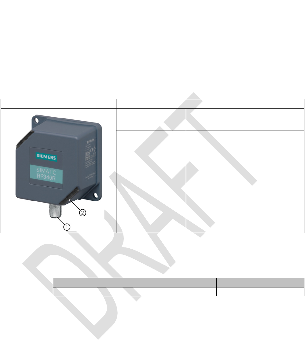
SIMATIC RF340R
Characteristics
Design ① RS-422 interface
②
Status display
Area of application Identification tasks on assembly lines in
harsh industrial environments
5.4.1.2
Ordering data for RF340R
Table 5- 11 Ordering data for RF340R
Article number
RF340R with RS-422 interface (3964R)
6GT2801-2AB10

Readers
5.4 SIMATIC RF340R/RF350R
SIMATIC RF300
System Manual, 07/2016, C79000-G8976-C345-0x 137
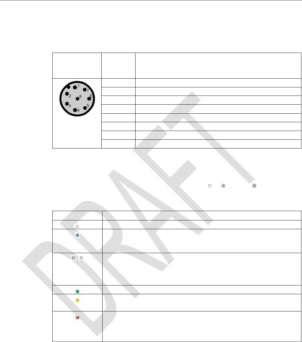
5.4.1.3
Pin assignment of RF340R RS422 interface
Pin
Pin
Device end
8-pin M12
Assignment
1
+ 24 V
2
- Transmit
3
0 V
4 + Transmit
5
+ Receive
6
- Receive
7
Unassigned
8
Earth (shield)
5.4.1.4
LED operating display
The operational statuses of the reader are displayed by the LEDs. The LED can adopt the
colors green, red or yellow and the statuses off , on , flashing :
Table 5- 12 LED operating display on the reader
Color
Meaning
Operating voltage present, reader not initialized or antenna switched off
Operating voltage present, reader initialized and antenna switched on
1)
Transponder present
Error has occurred, the type of flashing corresponds to the error code in the
table in the section Error codes. The optical error display is only reset if the
corresponding reset parameter ("option_1", see FC 45 / FB 45 documentation,
section Input parameters) is set.
1) Only in the "with presence" mode.
5.4.1.5
Ensuring reliable data exchange
The "center point" of the transponder must be situated within the transmission window.
Readers
5.4 SIMATIC RF340R/RF350R
SIMATIC RF300
138 System Manual, 07/2016, C79000-G8976-C345-0x
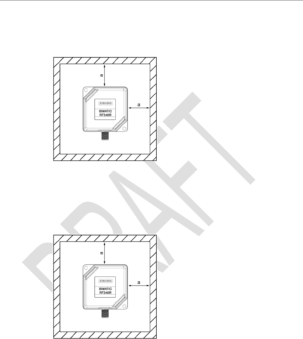
5.4.1.6
Metal-free area
The RF340R can be flush-mounted in metal. Please allow for a possible reduction in the field
data values.
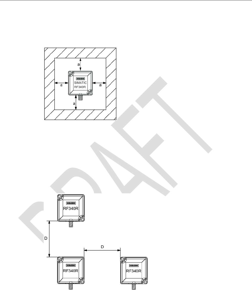
Figure 5-13 Metal-free area for RF340R
To avoid any impact on the field data, the distance a should be ≥ 20 mm.
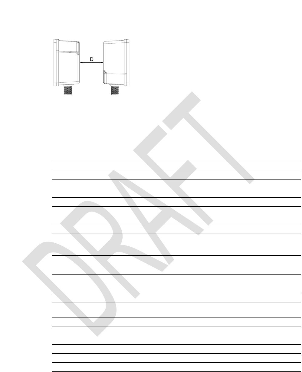
5.4.1.7
Minimum distance between RF340R readers
RF340R side by side
D
≥ 200 mm (with 2 readers)
D
≥ 250 mm (with more than 2 readers)
Figure 5-14 Minimum distance between RF340R readers
Readers
5.4 SIMATIC RF340R/RF350R
SIMATIC RF300
System Manual, 07/2016, C79000-G8976-C345-0x 139
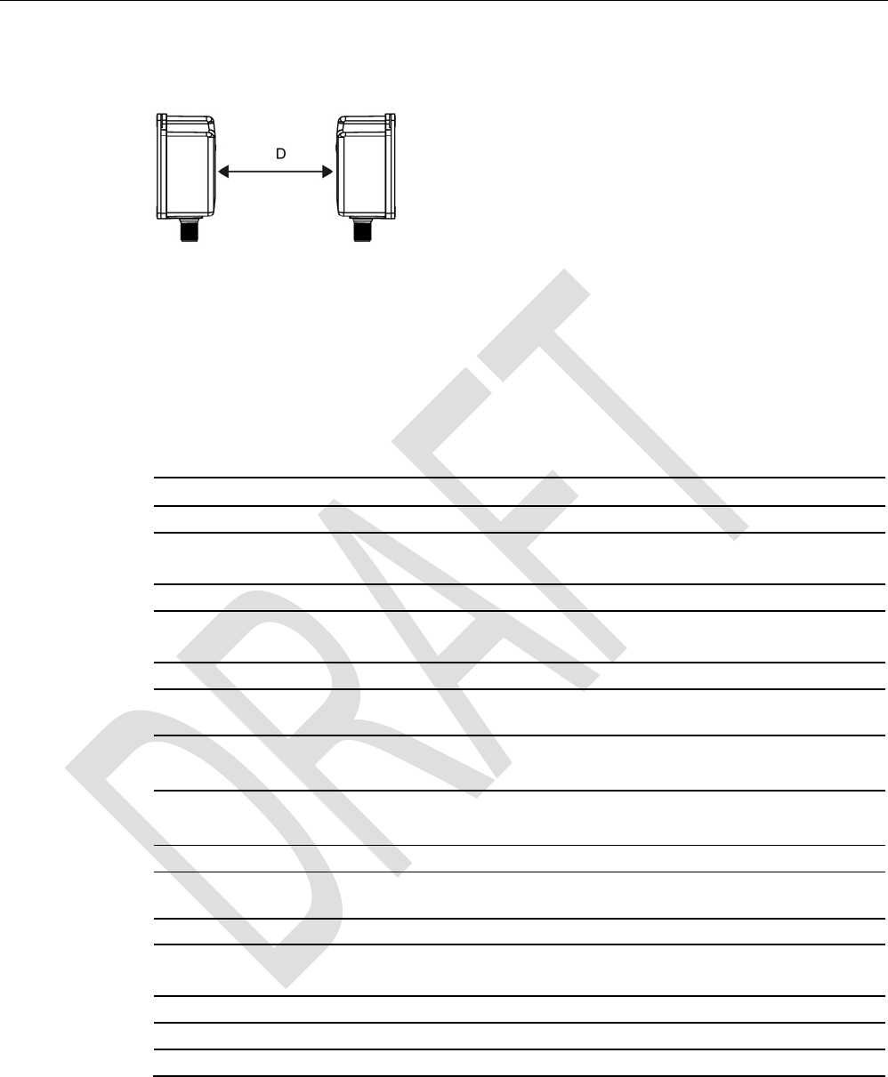
RF340R face-of-face
D
≥ 500 mm
Figure 5-15 Face-of-face distance between two RF340Rs
5.4.1.8
Technical specifications
Table 5- 13 Technical specifications of the RF340R reader
6GT2801-2AB10
Product type designation
SIMATIC RF340R
Radio frequencies
Operating frequency, rated value
13.56 MHz
Electrical data
Maximum range
140 mm
Maximum data transmission speed
reader ↔ transponder
RF300 transponder ISO transponder
• Read • approx. 8000
bytes/s
• approx. 1500
bytes/s
• Write • approx. 8000
bytes/s
• approx. 1500
bytes/s
Transmission speed
19.2, 57.6, 115.2 kBd
Read/write distances of the reader See section "Field data for transponders, readers
and antennas (Page 48)."
MTBF (Mean Time Between Failures)
140 years
Interfaces
Electrical connector design
M12, 8-pin
Standard for interfaces for communication
RS-422 (3964R protocol)
Antenna
integrated

Readers
5.4 SIMATIC RF340R/RF350R
SIMATIC RF300
140 System Manual, 07/2016, C79000-G8976-C345-0x
6GT2801-2AB10
Mechanical specifications
Housing
• Material • Plastic PA 12
• Color • Anthracite
Recommended distance to metal
0 mm
Supply voltage, current consumption, power loss
Supply voltage
24 VDC
Typical current consumption
100 mA
Permitted ambient conditions
Ambient temperature
• During operation • -25 to +70 ℃
• During transportation and storage • -40 to +85 ℃
Degree of protection to EN 60529
IP67
Shock-resistant to EN 60721-3-7, Class 7 M3
50 g
Vibration-resistant to EN 60721-3-7, Class 7 M3
20 g
Torsion and bending load
Not permitted
Design, dimensions and weight
Dimensions (L x W x H)
75 x 75 x 41 mm
Weight
250 g
Type of mounting 2 x M5 screws;
1.5 Nm
Cable length for RS-422 interface, maximum
1000 m
LED display design 3-color LED
Standards, specifications, approvals
Proof of suitability Radio to R&TTE directives EN 300330,
EN 301489, CE, FCC, UL/CSA,
Ex approval

Readers
5.4 SIMATIC RF340R/RF350R
SIMATIC RF300
System Manual, 07/2016, C79000-G8976-C345-0x 141
5.4.1.9
Approvals
FCC information
Siemens SIMATIC RF340R (MLFB 6GT2801-2AA10); FCC ID NXW-RF340R
Siemens SIMATIC RF340R (MLFB 6GT2801-2AB10); FCC ID NXW-RF340R01
This device complies with part 15 of the FCC rules. Operation is subject to the following two
conditions:
(1) This device may not cause harmful interference, and
(2) this device must accept any interference received, including interference that may cause
undesired operation.
Caution
Any changes or modifications not expressly approved by the party responsible for
compliance could void the user's authority to operate the equipment.
Note
This equipment has been tested and found to comply with the limits for a Class A digital
device, pursuant to part 15 of the FCC Rules.
These limits are designed to provide reasonable protection against harmful interference
when the equipment is operated in a commercial environment. This equipment generates,
uses, and can radiate radio frequency energy and, if not installed and used in accordance
with the instruction manual, may cause harmful interference to radio communications.
Operation of this equipment in a residential area is likely to cause harmful interference in
which case the user will be required to correct the interference at his own expense.
IC information
This device complies with Industry Canada licence-exempt RSS standard(s). Operation is
subject to the following two conditions:
(1) This device may not cause interference, and
(2) this device must accept any interference, including interference that may cause
undesired operation of the device.
Le présent appareil est conforme aux CNR d`Industrie Canada applicables aux appareils
radio exempts de licence. L`exploitation est autorisée aux deux conditions suivantes :
(1) L`appareil ne doit pas produire de brouillage, et
(2) l'utilisateur de l`appareil doit accepter tout brouillage radioélectrique subi, même si le
brouillage est susceptible d`en compromettre le fonctionnement.
Readers
5.4 SIMATIC RF340R/RF350R
SIMATIC RF300
142 System Manual, 07/2016, C79000-G8976-C345-0x
5.4.1.10
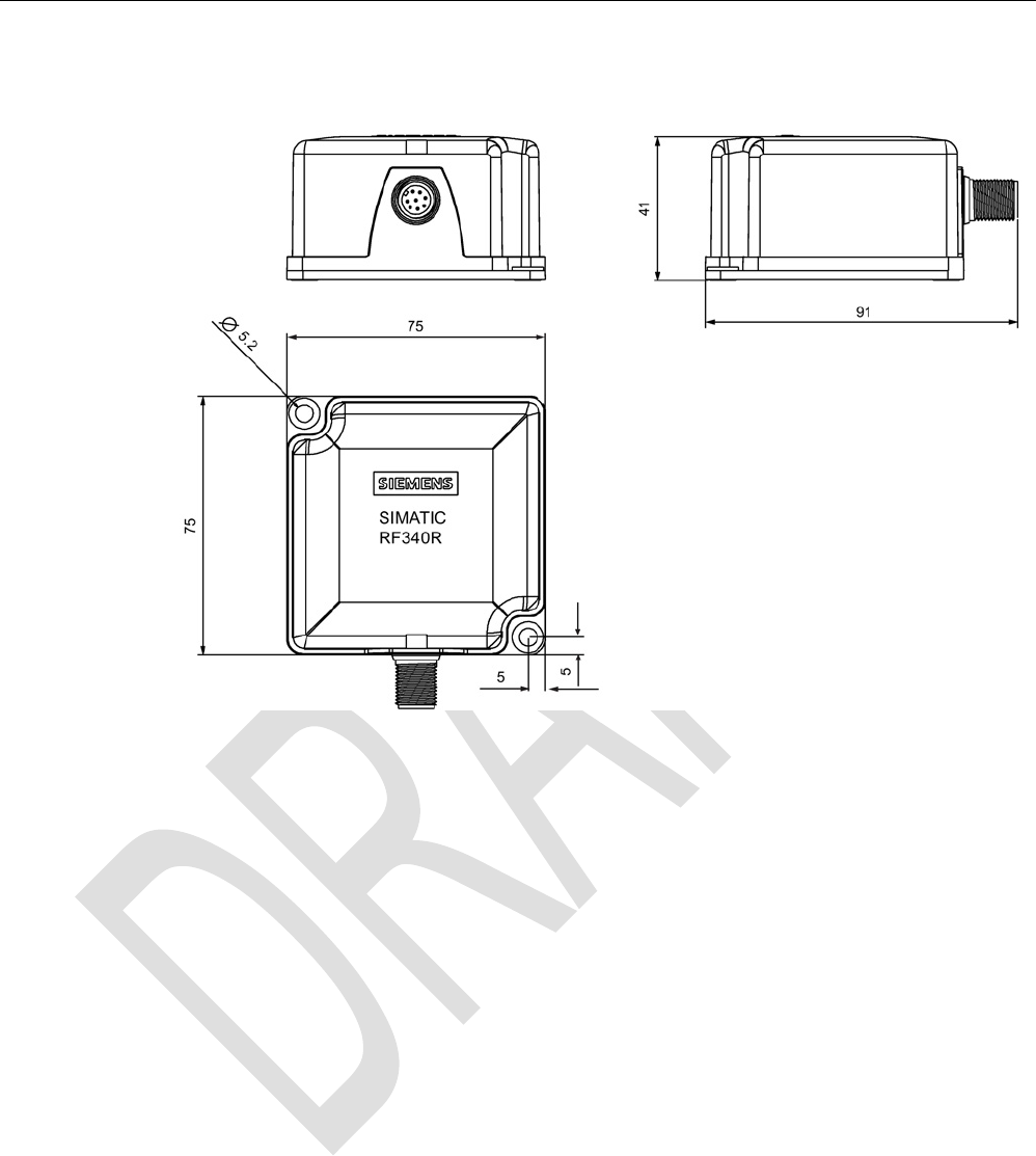
Dimension drawing
Figure 5-16 Dimension drawing for RF340R
Dimensions in mm
Readers
5.4 SIMATIC RF340R/RF350R
SIMATIC RF300
System Manual, 07/2016, C79000-G8976-C345-0x 143
5.4.2
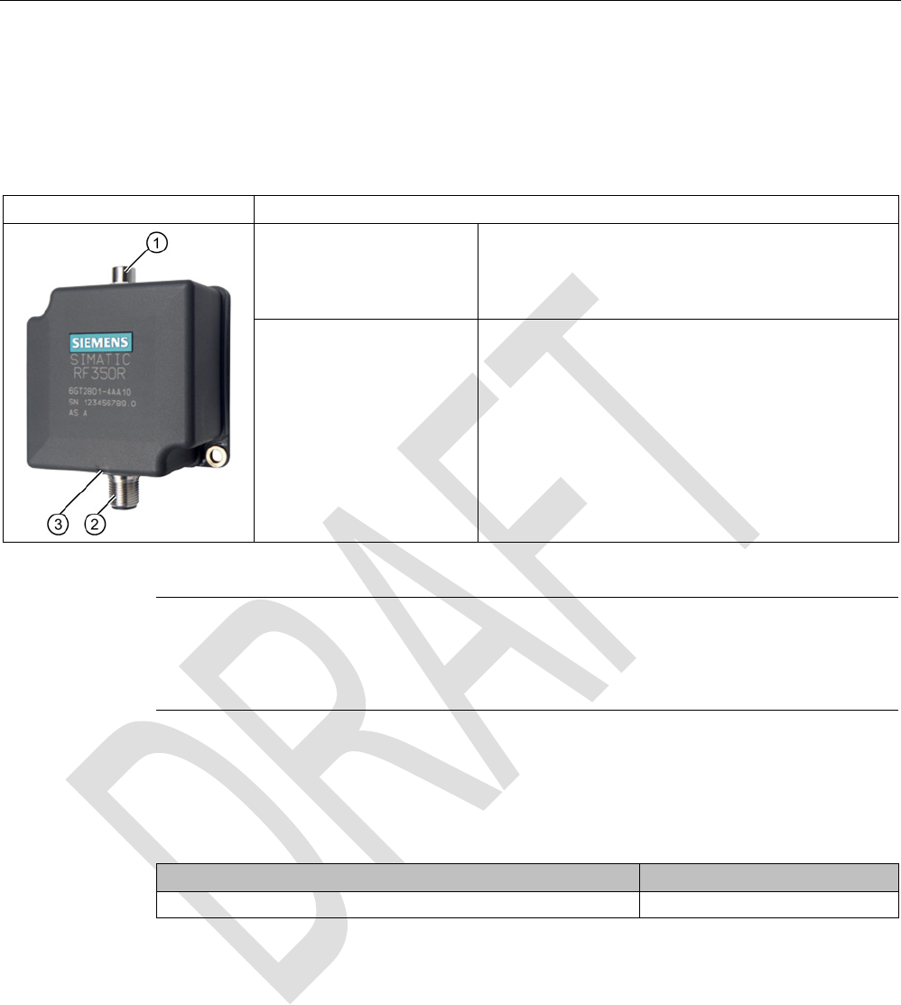
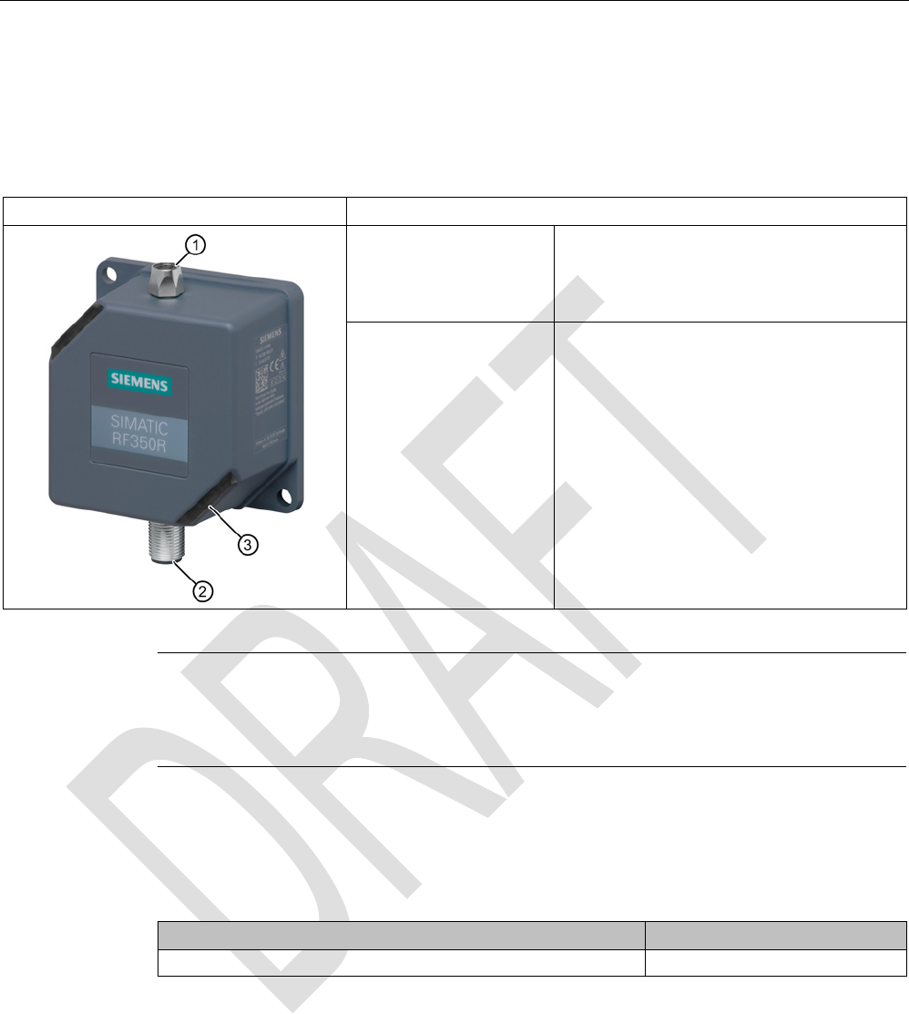
SIMATIC RF350R
5.4.2.1
Features
SIMATIC RF350R
Characteristics
Design ① Antenna connection
② RS-422 interface
③
Status display
Area of application Identification tasks in assembly lines in harsh industrial
environments; for external antennas
(ANT 1, ANT 3, ANT 12, ANT 18, ANT 30)
Note
Reader requires external antennas
Note that the RF350R reader is designed only for operation with external antennas and only
works in conjunction with the antennas ANT 1, ANT 3, ANT 12, ANT 18 or ANT 30.
5.4.2.2
Ordering data for RF350R
Table 5- 14 Ordering data for RF350R
Article number
RF350R with RS-422 interface (3964R)
6GT2801-4AB10
Readers
5.4 SIMATIC RF340R/RF350R
SIMATIC RF300
144 System Manual, 07/2016, C79000-G8976-C345-0x
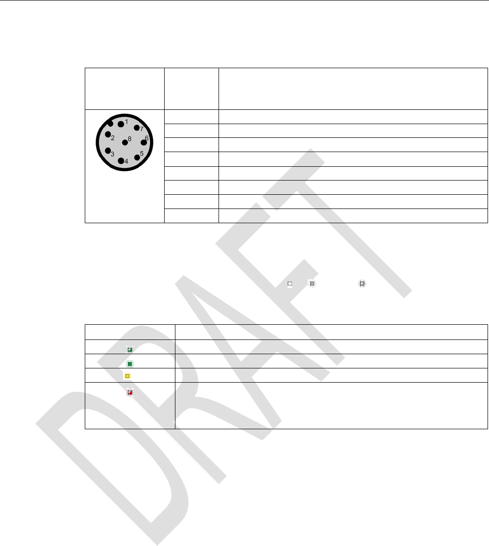
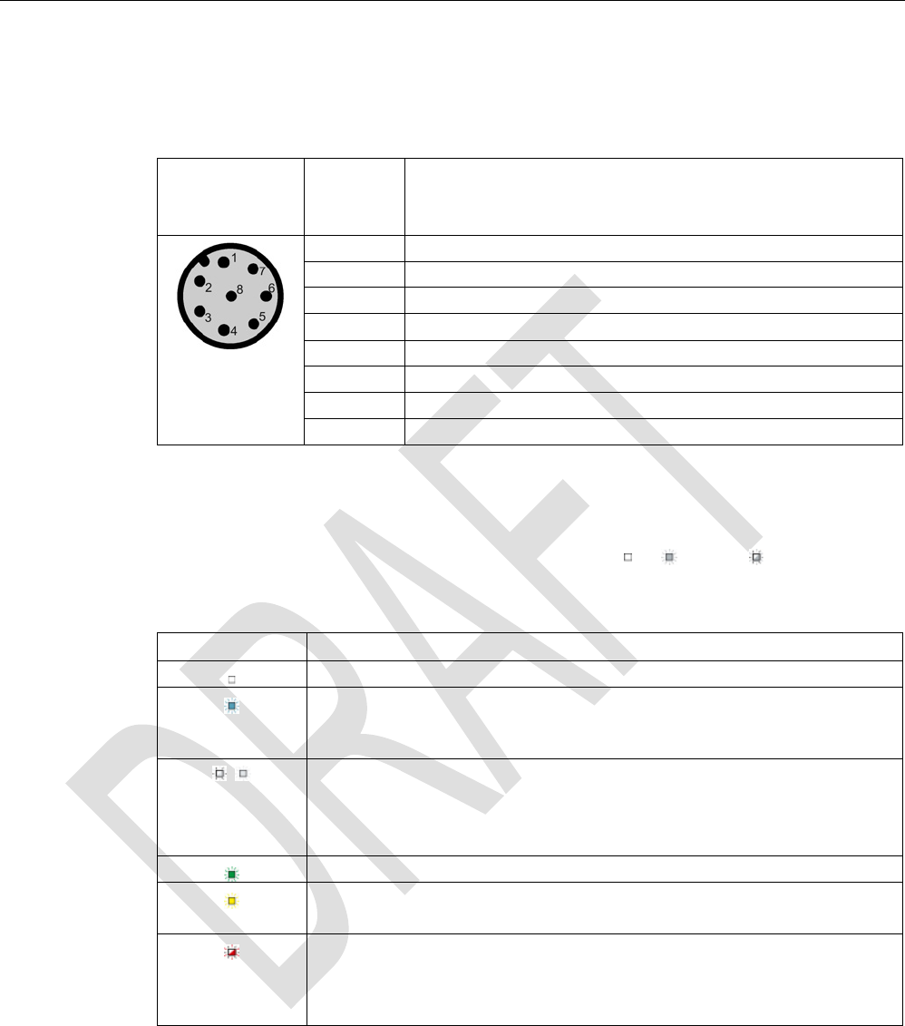
5.4.2.3
Pin assignment of RF350R RS422 interface
Pin
Pin
Device end
8-pin M12
Assignment
1
+ 24 V
2
- Transmit
3
0 V
4 + Transmit
5
+ Receive
6
- Receive
7
Unassigned
8
Earth (shield)
5.4.2.4
LED operating display
The operational statuses of the reader are displayed by the LEDs. The LED can adopt the
colors green, red or yellow and the statuses off , on , flashing :
Table 5- 15 LED operating display on the reader
Color
Meaning
Operating voltage present, reader not initialized or antenna switched off
Operating voltage present, reader initialized and antenna switched on
1)
Transponder present
Error has occurred, the type of flashing corresponds to the error code in the
table in the section Error codes. The optical error display is only reset if the
corresponding reset parameter ("option_1", see FC 45 / FB 45 documentation,
section Input parameters) is set.
1) Only in the "with presence" mode.
5.4.2.5
Ensuring reliable data exchange
The "center point" of the transponder must be situated within the transmission window.
5.4.2.6
Metal-free area
The RF350R reader does not have an internal antenna. Operation is not affected by
mounting on metal or flush-mounting in metal. For information about the metal-free area
required by the external antennas, refer to the corresponding section of the chapter Auto-
Hotspot.

Readers
5.4 SIMATIC RF340R/RF350R
SIMATIC RF300
System Manual, 07/2016, C79000-G8976-C345-0x 145
5.4.2.7
Technical specifications
Table 5- 16 Technical specifications of the RF350R reader
6GT2801-4AB10
Product type designation
SIMATIC RF350R
Radio frequencies
Operating frequency, rated value
13.56 MHz
Electrical data
Maximum range
• ANT 1 • 140 mm
• ANT 3 • 50 mm
• ANT 12 • 16 mm
• ANT 18 • 35 mm
• ANT 30 • 55 mm
Maximum data transmission speed
reader ↔ transponder
RF300 transponder ISO transponder
• Read • approx. 8000
bytes/s
• approx. 1500
bytes/s
• Write • approx. 8000
bytes/s
• approx. 1500
bytes/s
Transmission speed
19.2, 57.6, 115.2 kBd
Read/write distances of the reader See section "Field data for transponders, readers
and antennas (Page 48)."
MTBF (Mean Time Between Failures)
140 years
Interfaces
Electrical connector design
M12, 8-pin
Antenna connector design
M8, 4-pin
Standard for interfaces for communication
RS-422 (3964R protocol)
Antenna External, antennas ANT 1, ANT 3, ANT 12, ANT
18 or ANT 30
Mechanical specifications
Housing
• Material • Plastic PA 12
• Color • Anthracite
Recommended distance to metal
0 mm

Readers
5.4 SIMATIC RF340R/RF350R
SIMATIC RF300
146 System Manual, 07/2016, C79000-G8976-C345-0x
6GT2801-4AB10
Supply voltage, current consumption, power loss
Supply voltage
24 VDC
Typical current consumption
100 mA
Permitted ambient conditions
Ambient temperature
• During operation • -25 to +70 ℃
• During transportation and storage • -40 to +85 ℃
Degree of protection to EN 60529
IP65
Shock-resistant to EN 60721-3-7, Class 7 M3
50 g
Vibration-resistant to EN 60721-3-7, Class 7 M3
20 g
Torsion and bending load
Not permitted
Design, dimensions and weight
Dimensions (L x W x H)
75 x 75 x 41 mm
Weight
250 g
Type of mounting 2 x M5 screws;
1.5 Nm
Cable length for RS-422 interface, maximum
1000 m
LED display design
3-color LED
Standards, specifications, approvals
Proof of suitability Radio to R&TTE directives EN 300330,
EN 301489, CE, FCC, UL/CSA,
Ex approval

Readers
5.4 SIMATIC RF340R/RF350R
SIMATIC RF300
System Manual, 07/2016, C79000-G8976-C345-0x 147
5.4.2.8
Approvals
FCC information
Siemens SIMATIC RF350R (MLFB 6GT2801-4AA10); FCC ID NXW-RF350R
Siemens SIMATIC RF350R (MLFB 6GT2801-4AB10); FCC ID NXW-RF350R01
This device complies with part 15 of the FCC rules. Operation is subject to the following two
conditions:
(1) This device may not cause harmful interference, and
(2) this device must accept any interference received, including interference that may cause
undesired operation.
Caution
Any changes or modifications not expressly approved by the party responsible for
compliance could void the user's authority to operate the equipment.
Note
This equipment has been tested and found to comply with the limits for a Class A digital
device, pursuant to part 15 of the FCC Rules.
These limits are designed to provide reasonable protection against harmful interference
when the equipment is operated in a commercial environment. This equipment generates,
uses, and can radiate radio frequency energy and, if not installed and used in accordance
with the instruction manual, may cause harmful interference to radio communications.
Operation of this equipment in a residential area is likely to cause harmful interference in
which case the user will be required to correct the interference at his own expense.
IC information
This device complies with Industry Canada licence-exempt RSS standard(s). Operation is
subject to the following two conditions:
(1) This device may not cause interference, and
(2) this device must accept any interference, including interference that may cause
undesired operation of the device.
Le présent appareil est conforme aux CNR d`Industrie Canada applicables aux appareils
radio exempts de licence. L`exploitation est autorisée aux deux conditions suivantes :
(1) L`appareil ne doit pas produire de brouillage, et
(2) l'utilisateur de l`appareil doit accepter tout brouillage radioélectrique subi, même si le
brouillage est susceptible d`en compromettre le fonctionnement.
Readers
5.4 SIMATIC RF340R/RF350R
SIMATIC RF300
148 System Manual, 07/2016, C79000-G8976-C345-0x
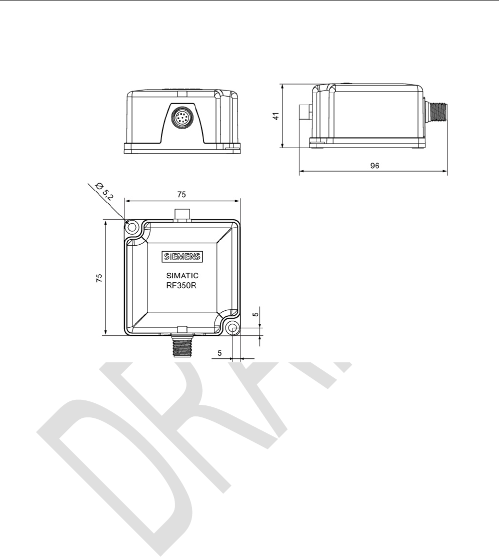
5.4.2.9
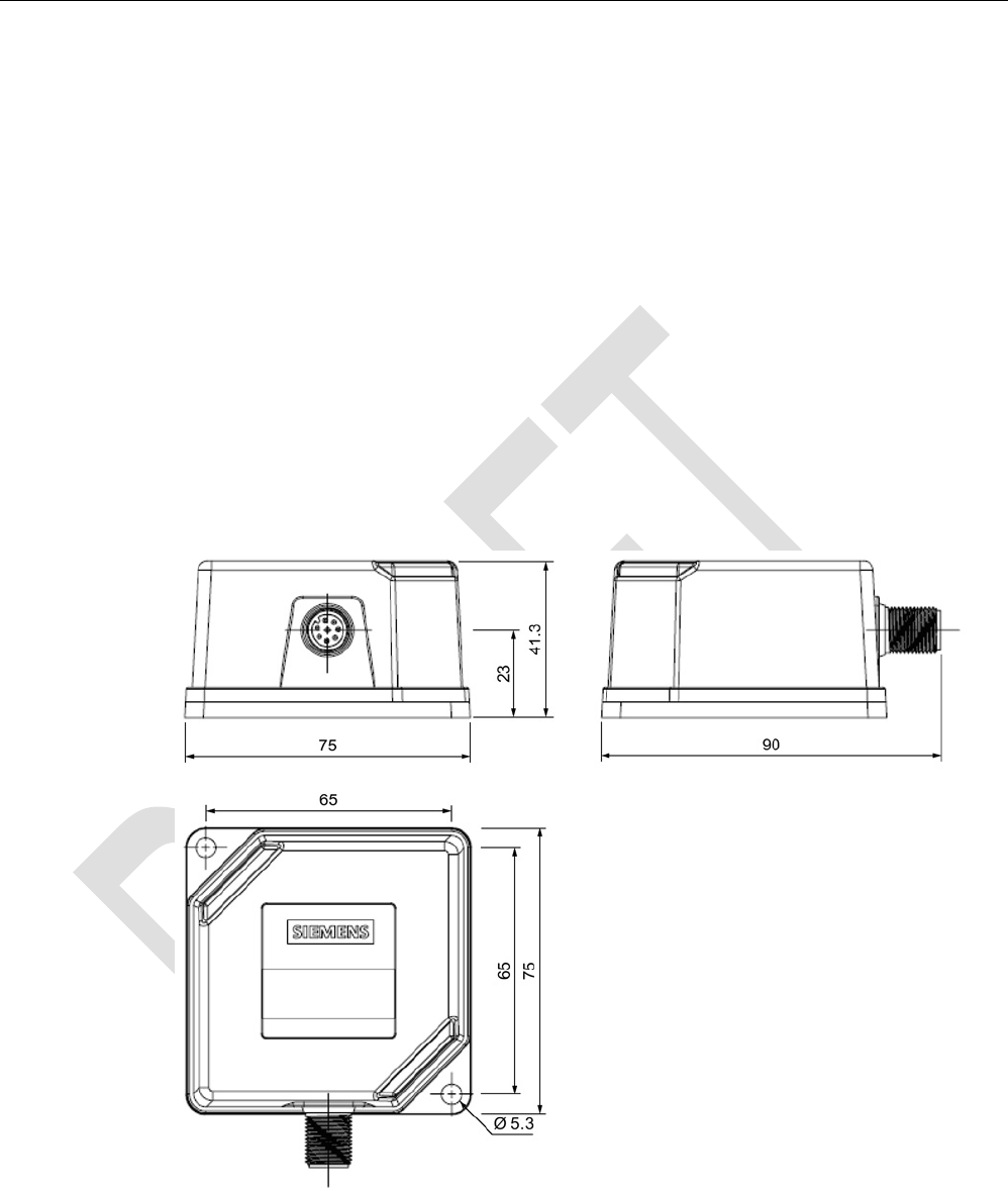
Dimension drawing
Figure 5-17 RF350R dimension drawing
Dimensions in mm
Readers
5.4 SIMATIC RF340R/RF350R
SIMATIC RF300
System Manual, 07/2016, C79000-G8976-C345-0x 149
5.4.3
Use of the reader in hazardous areas
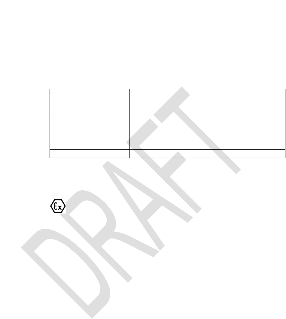
TÜV NORD CERT GmbH as accredited test center and certification body, no. 0044 as per
Article 9 of the Directive 94/9/EC of the European Council of 23 March 1994, has confirmed
the compliance with the essential health and safety requirements relating to the design and
construction of equipment and protective systems intended for use in hazardous areas as
per Annex II of the Directive. The essential health and safety requirements are satisfied in
accordance with the following standards:
Document
Title
EN 60079-0: 2006 Electrical equipment for hazardous gas atmospheres -
Part 0: General requirements
EN 60079-15: 2005 Electrical equipment for hazardous gas atmospheres -
Part 15: Design, testing and identification of electrical equipment with
type of protection "n"
IEC 61241 -0: 2006 Electrical apparatus for use in the presence of combustible dust -
Part 0: General requirements
IEC 61241 -1: 2004 Electrical apparatus for use in the presence of combustible dust -
Part 1: Protection through enclosure
WARNING
EXPLOSION HAZARD
DO NOT CONNECT OR DISCONNECT EQUIPMENT WHEN A FLAMMABLE OR
COMBUSTIBLE ATMOSPHERE IS PRESENT.
Identification
The identification of the electrical equipment as an enclosed unit is:
II 3 G Ex nA nC IIB T5
II 3 D Ex tD A22 IP6x T80 °C
-25 °C to +70 °C
U
n
= 20 to 30 VDC
The equipment also has the following additional markings:
XXXYYYZZZ
[= serial number, is assigned during production]
TÜV 10 ATEX 556039
[= certificate number]
Readers
5.4 SIMATIC RF340R/RF350R
SIMATIC RF300
150 System Manual, 07/2016, C79000-G8976-C345-0x
5.4.3.1
Use of the readers in hazardous areas for gases
Temperature class delineation for gases
The temperature class of the reader for hazardous areas depends on the ambient
temperature range:
Ambient temperature range
Temperature class
-25 °C to +70 °C
T5
WARNING
Ignitions of gas-air mixtures
When using the RF340R/RF350R readers, check to ensure that the temperature class is
observed in respect of the requirements of the area of application.
Non-compliance with the permitted temperature ranges while using the reader can lead to
ignitions of gas-air mixtures.
5.4.3.2
Use of the readers in hazardous areas for dusts
The equipment is suitable for dusts whose ignition temperatures for a dust layer of 5 mm are
higher than 80 °C (smoldering temperature). With the ignition temperature according to type
of protection iD specified here in compliance with IEC 61241-0 and IEC 61241-11, the
smoldering temperature of the dust layer is referenced in this case.
Temperature class delineation for dusts
Ambient temperature range
Temperature value
-25 °C < Ta < +70 °C T80 °C
WARNING
Ignitions of dust-air mixtures
When using the RF340R/RF350R readers, check to ensure that the temperature values are
observed in respect of the requirements of the area of application.
Non-compliance with the permitted temperature ranges while using the reader can lead to
ignitions of dust-air mixtures.

Readers
5.4 SIMATIC RF340R/RF350R
SIMATIC RF300
System Manual, 07/2016, C79000-G8976-C345-0x 151
5.4.3.3
Installation and operating conditions for the hazardous area
NOTICE
Device may be damaged
Note the following conditions when installing and operating the device in a hazardous zone
to avoid damage:
• Making and breaking of circuits is permitted only in a de-energized state.
• The maximum surface temperature, corresponding to the marking, applies only for
operation without a cover of dust.
• The device may only be operated in such a way that adequate protection against UV
light is ensured.
• The device may not be operated in areas influenced by processes that generate high
electrostatic charges.
• The equipment must be installed so that it is mechanically protected.
• The device sockets must be protected with a shrink-on tube.
• The 8 pin connector must be grounded via its supply line.
• The device may only be operated with accessories specified or supplied by the
manufacturer. All the points above also apply to the accessories (cables and
connectors) and to the antennas (exception: the housing of antenna 1 does not need to
be installed with impact protection).
Readers
5.5 SIMATIC RF340R/RF350R - second generation
SIMATIC RF300
152 System Manual, 07/2016, C79000-G8976-C345-0x
5.5
SIMATIC RF340R/RF350R - second generation
5.5.1
SIMATIC RF340R - second generation
5.5.1.1
Features
SIMATIC RF340R
Characteristics
Design ① RS-422 interface
②
LED operating display
Area of application Identification tasks on assembly lines in harsh
industrial environments
5.5.1.2
Ordering data
Table 5- 17 Ordering data for RF340R
Article number
RF340R with RS-422 interface (3964R)
6GT2801-2BA10
Readers
5.5 SIMATIC RF340R/RF350R - second generation
SIMATIC RF300
System Manual, 07/2016, C79000-G8976-C345-0x 153
5.5.1.3
Pin assignment of the RS-422 interface
Table 5- 18 Pin assignment
Pin
Pin
Device end
8-pin M12
Assignment
1
+ 24 V
2
- Transmit
3
0 V
4 + Transmit
5
+ Receive
6
- Receive
7
Unassigned
8
Earth (shield)
5.5.1.4
LED operating display
The operational statuses of the reader are displayed by two LEDs. The LEDs can adopt the
colors white green, red, yellow or blue and the statuses off , on , flashing :
Table 5- 19 Display elements
LED
Meaning
The reader is turned off.
The reader is turned on and is searching for transponders.
The reader is in the "Setup" mode, in the "Search for transponders" status and
has not yet received a "RESET" command and is not ready.
/ There is transponder in the antenna field.
The reader is in the "Setup" mode, in the status "Show quality", has not yet re-
ceived a "RESET" command and is not ready.
Depending on the signal strength, the LED flashes or is lit permanently.
The reader has received a "RESET" command.
There is transponder in the antenna field.
The reader is ready.
There is an error. The number of flashes provides information about the current
error.
You will find more information on error messages in the section "System diag-
nostics (Page 395)".
5.5.1.5
Ensuring reliable data exchange
The "center point" of the transponder must be situated within the transmission window.
Readers
5.5 SIMATIC RF340R/RF350R - second generation
SIMATIC RF300
154 System Manual, 07/2016, C79000-G8976-C345-0x
5.5.1.6
Metal-free area
The RF340R can be flush-mounted in metal. Allow for a possible reduction in the field data.
To avoid any influence on the field data, the distance "a" should be kept to.
a ≥
20 mm
Figure 5-18 Metal-free area for RF340R
5.5.1.7
Minimum distance between RF340R readers
RF340R side by side
D ≥
200 mm (with 2 readers)
D ≥
250 mm (with more than 2 readers)
Figure 5-19 Minimum distance between RF340R readers
Readers
5.5 SIMATIC RF340R/RF350R - second generation
SIMATIC RF300
System Manual, 07/2016, C79000-G8976-C345-0x 155
RF340R face-of-face
D ≥
500 mm
Figure 5-20 Face-of-face distance between two RF340Rs
5.5.1.8
Technical specifications
Table 5- 20 Technical specifications of the RF340R reader
6GT2801-2BA10
Product type designation
SIMATIC RF340R
Radio frequencies
Operating frequency, rated value
13.56 MHz
Electrical data
Maximum range
140 mm
Maximum data transmission speed
reader ↔ transponder
RF300
transponder
ISO
transponder
(MDS D)
ISO tran-
sponder
(MDS E)
• Read • ≤ 8000
bytes/s
• ≤ 3300
bytes/s
• ≤ 3400
bytes/s
• Write • ≤ 8000
bytes/s
• ≤ 1700
bytes/s
• ≤ 800
bytes/s
Transmission speed
19.2, 57.6, 115.2 kBd
Read/write distances of the reader See section "Field data for transponders, readers
and antennas (Page 48)."
MTBF (Mean Time Between Failures)
260 years
Interfaces
Electrical connector design
M12, 8-pin
Standard for interfaces for communication
RS-422 (3964R protocol)
Antenna
integrated

Readers
5.5 SIMATIC RF340R/RF350R - second generation
SIMATIC RF300
156 System Manual, 07/2016, C79000-G8976-C345-0x
6GT2801-2BA10
Mechanical specifications
Housing
• Material • Plastic PA 12
• Color • TI-Grey
Recommended distance to metal
0 mm
Supply voltage, current consumption, power loss
Supply voltage
24 VDC
Typical current consumption
55 mA
Permitted ambient conditions
Ambient temperature
• During operation • -25 to +70 ℃
• During transportation and storage • -40 to +85 ℃
Degree of protection to EN 60529
IP67
Shock-resistant to EN 60721-3-7, Class 7 M3
50 g
Vibration-resistant to EN 60721-3-7, Class 7 M3
20 g
Torsion and bending load
Not permitted
Design, dimensions and weight
Dimensions (L x W x H)
75 x 75 x 41 mm
Weight
210 g
Type of mounting 2 x M5 screws;
1.5 Nm
Cable length for RS-422 interface, maximum
1000 m
LED display design 2 LEDs,
5 colors
Standards, specifications, approvals
Proof of suitability Radio to R&TTE directives EN 300330,
EN 301489, CE, FCC, UL/CSA (IEC61010 /
IEC61010-2-201),
Ex approval

Readers
5.5 SIMATIC RF340R/RF350R - second generation
SIMATIC RF300
System Manual, 07/2016, C79000-G8976-C345-0x 157
5.5.1.9
Approvals
FCC information
Siemens SIMATIC RF340R (MLFB 6GT2801-2BA10); FCC ID NXW-RF340R02
This device complies with part 15 of the FCC rules. Operation is subject to the following two
conditions:
(1) This device may not cause harmful interference, and
(2) this device must accept any interference received, including interference that may cause
undesired operation.
Caution
Any changes or modifications not expressly approved by the party responsible for
compliance could void the user's authority to operate the equipment.
Note
This equipment has been tested and found to comply with the limits for a Class A digital
device, pursuant to part 15 of the FCC Rules.
These limits are designed to provide reasonable protection against harmful interference
when the equipment is operated in a commercial environment. This equipment generates,
uses, and can radiate radio frequency energy and, if not installed and used in accordance
with the instruction manual, may cause harmful interference to radio communications.
Operation of this equipment in a residential area is likely to cause harmful interference in
which case the user will be required to correct the interference at his own expense.
IC information
This device complies with Industry Canada licence-exempt RSS standard(s). Operation is
subject to the following two conditions:
(1) This device may not cause interference, and
(2) this device must accept any interference, including interference that may cause
undesired operation of the device.
Le présent appareil est conforme aux CNR d`Industrie Canada applicables aux appareils
radio exempts de licence. L`exploitation est autorisée aux deux conditions suivantes :
(1) L`appareil ne doit pas produire de brouillage, et
(2) l'utilisateur de l`appareil doit accepter tout brouillage radioélectrique subi, même si le
brouillage est susceptible d`en compromettre le fonctionnement.
Readers
5.5 SIMATIC RF340R/RF350R - second generation
SIMATIC RF300
158 System Manual, 07/2016, C79000-G8976-C345-0x
UL information (IEC61010-1 / IEC61010-2-201)
This standard applies to equipment designed to be safe at least under the following
conditions:
● a) indoor use;
● b) altitude up to 2 000 m;
● c) temperature -25 °C to 70 °C;
● d) maximum relative humidity 80 % for temperature up to 31 °C decreasing linearly to 50
% relative humidity at 40 °C;
● e) TRANSIENT OVERVALTAGES up to the levels of OVERVALTAGE CATEGORY II,
NOTE 1: These levels of transient overvoltage are typical for equipment supplied from the
building wiring.
● f) using a "NEC Class 2" power supply is required
5.5.1.10
Dimension drawing
Figure 5-21 Dimension drawing for RF340R
Dimensions in mm
Readers
5.5 SIMATIC RF340R/RF350R - second generation
SIMATIC RF300
System Manual, 07/2016, C79000-G8976-C345-0x 159
5.5.2
SIMATIC RF350R - second generation
5.5.2.1
Features
SIMATIC RF350R
Characteristics
Design ① Antenna connection
② RS-422 interface
③
LED operating display
Area of application Identification tasks in assembly lines in harsh
industrial environments; for external antennas
(ANT 1, ANT 3, ANT 12, ANT 18, ANT 30)
Note
Reader requires external antennas
Note that the RF350R reader is designed only for operation with external antennas and only
works in conjunction with the antennas ANT 1, ANT 3, ANT 12, ANT 18 or ANT 30.
5.5.2.2
Ordering data
Table 5- 21 Ordering data for RF350R
Article number
RF350R with RS-422 interface (3964R)
6GT2801-4BA10
Readers
5.5 SIMATIC RF340R/RF350R - second generation
SIMATIC RF300
160 System Manual, 07/2016, C79000-G8976-C345-0x
5.5.2.3
Pin assignment of the RS-422 interface
Table 5- 22 Pin assignment
Pin
Pin
Device end
8-pin M12
Assignment
1
+ 24 V
2
- Transmit
3
0 V
4 + Transmit
5
+ Receive
6
- Receive
7
Unassigned
8
Earth (shield)
5.5.2.4
LED operating display
The operational statuses of the reader are displayed by two LEDs. The LEDs can adopt the
colors white green, red, yellow or blue and the statuses off , on , flashing :
Table 5- 23 Display elements
LED
Meaning
The reader is turned off.
The reader is turned on and is searching for transponders.
The reader is in the "Setup" mode, in the "Search for transponders" status and
has not yet received a "RESET" command and is not ready.
/ There is transponder in the antenna field.
The reader is in the "Setup" mode, in the status "Show quality", has not yet re-
ceived a "RESET" command and is not ready.
Depending on the signal strength, the LED flashes or is lit permanently.
The reader has received a "RESET" command.
There is transponder in the antenna field.
The reader is ready.
There is an error. The number of flashes provides information about the current
error.
You will find more information on error messages in the section "System diag-
nostics (Page 395)".
5.5.2.5
Ensuring reliable data exchange
The "center point" of the transponder must be situated within the transmission window.

Readers
5.5 SIMATIC RF340R/RF350R - second generation
SIMATIC RF300
System Manual, 07/2016, C79000-G8976-C345-0x 161
5.5.2.6
Metal-free area
The RF350R reader does not have an internal antenna. Operation is not affected by
mounting on metal or flush-mounting in metal. For information about the metal-free area
required by the external antennas, refer to the corresponding section of the chapter
"Antennas (Page 193)".
5.5.2.7
Technical specifications
Table 5- 24 Technical specifications of the RF350R reader
6GT2801-4BA10
Product type designation
SIMATIC RF350R
Radio frequencies
Operating frequency, rated value
13.56 MHz
Electrical data
Maximum range
• ANT 1 • 140 mm
• ANT 3 • 50 mm
• ANT 12 • 16 mm
• ANT 18 • 35 mm
• ANT 30 • 55 mm
Maximum data transmission speed
reader ↔ transponder
RF300
transponder
ISO
transponder
(MDS D)
ISO tran-
sponder
(MDS E)
• Read • ≤ 8000
bytes/s
• ≤ 3300
bytes/s
• ≤ 3400
bytes/s
• Write • ≤ 8000
bytes/s
• ≤ 1700
bytes/s
• ≤ 800
bytes/s
Transmission speed
19.2, 57.6, 115.2 kBd
Read/write distances of the reader See section "Field data for transponders, readers
and antennas (Page 48)."
MTBF (Mean Time Between Failures)
260 years
Interfaces
Electrical connector design
M12, 8-pin
Antenna connector design
M8, 4-pin
Standard for interfaces for communication
RS-422 (3964R protocol)
Antenna External, antennas ANT 1, ANT 3, ANT 12, ANT
18 or ANT 30

Readers
5.5 SIMATIC RF340R/RF350R - second generation
SIMATIC RF300
162 System Manual, 07/2016, C79000-G8976-C345-0x
6GT2801-4BA10
Mechanical specifications
Housing
• Material • Plastic PA 12
• Color • TI-Grey
Recommended distance to metal
0 mm
Supply voltage, current consumption, power loss
Supply voltage
24 VDC
Typical current consumption
55 mA
Permitted ambient conditions
Ambient temperature
• During operation • -25 to +70 ℃
• During transportation and storage • -40 to +85 ℃
Degree of protection to EN 60529
IP65
Shock-resistant to EN 60721-3-7, Class 7 M3
50 g
Vibration-resistant to EN 60721-3-7, Class 7 M3
20 g
Torsion and bending load
Not permitted
Design, dimensions and weight
Dimensions (L x W x H)
75 x 75 x 41 mm
Weight
250 g
Type of mounting 2 x M5 screws;
1.5 Nm
Cable length for RS-422 interface, maximum
1000 m
LED display design 2 LEDs,
5 colors
Standards, specifications, approvals
Proof of suitability Radio to R&TTE directives EN 300330,
EN 301489, CE, FCC, UL/CSA (IEC61010 /
IEC61010-2-201),
Ex approval

Readers
5.5 SIMATIC RF340R/RF350R - second generation
SIMATIC RF300
System Manual, 07/2016, C79000-G8976-C345-0x 163
5.5.2.8
Approvals
FCC information
Siemens SIMATIC RF350R (MLFB 6GT2801-4BA10); FCC ID NXW-RF350R02
This device complies with part 15 of the FCC rules. Operation is subject to the following two
conditions:
(1) This device may not cause harmful interference, and
(2) this device must accept any interference received, including interference that may cause
undesired operation.
Caution
Any changes or modifications not expressly approved by the party responsible for
compliance could void the user's authority to operate the equipment.
Note
This equipment has been tested and found to comply with the limits for a Class A digital
device, pursuant to part 15 of the FCC Rules.
These limits are designed to provide reasonable protection against harmful interference
when the equipment is operated in a commercial environment. This equipment generates,
uses, and can radiate radio frequency energy and, if not installed and used in accordance
with the instruction manual, may cause harmful interference to radio communications.
Operation of this equipment in a residential area is likely to cause harmful interference in
which case the user will be required to correct the interference at his own expense.
IC information
This device complies with Industry Canada licence-exempt RSS standard(s). Operation is
subject to the following two conditions:
(1) This device may not cause interference, and
(2) this device must accept any interference, including interference that may cause
undesired operation of the device.
Le présent appareil est conforme aux CNR d`Industrie Canada applicables aux appareils
radio exempts de licence. L`exploitation est autorisée aux deux conditions suivantes :
(1) L`appareil ne doit pas produire de brouillage, et
(2) l'utilisateur de l`appareil doit accepter tout brouillage radioélectrique subi, même si le
brouillage est susceptible d`en compromettre le fonctionnement.
Readers
5.5 SIMATIC RF340R/RF350R - second generation
SIMATIC RF300
164 System Manual, 07/2016, C79000-G8976-C345-0x
UL information (IEC61010-1 / IEC61010-2-201)
This standard applies to equipment designed to be safe at least under the following
conditions:
● a) indoor use;
● b) altitude up to 2 000 m;
● c) temperature -25 °C to 70 °C;
● d) maximum relative humidity 80 % for temperature up to 31 °C decreasing linearly to 50
% relative humidity at 40 °C;
● e) TRANSIENT OVERVALTAGES up to the levels of OVERVALTAGE CATEGORY II,
NOTE 1: These levels of transient overvoltage are typical for equipment supplied from the
building wiring.
● f) using a "NEC Class 2" power supply is required
5.5.2.9
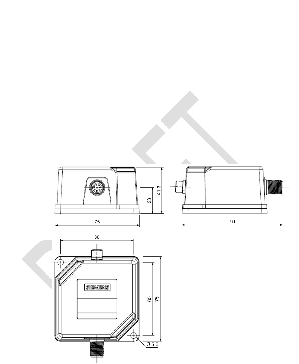
Dimension drawing
Figure 5-22 RF350R dimension drawing
Dimensions in mm

Readers
5.5 SIMATIC RF340R/RF350R - second generation
SIMATIC RF300
System Manual, 07/2016, C79000-G8976-C345-0x 165
5.5.3
Use of the reader in hazardous areas
NOTICE
Approvals for the hazardous area
The approvals for the hazardous area of the readers SIMATIC RF340R und RF350R are
currently in preparation.
Readers
5.6 SIMATIC RF380R
SIMATIC RF300
166 System Manual, 07/2016, C79000-G8976-C345-0x
5.6
SIMATIC RF380R
5.6.1
Features
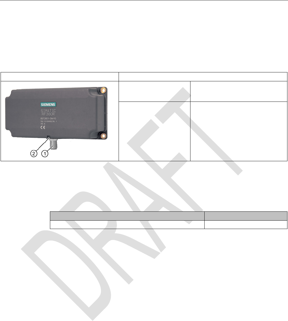
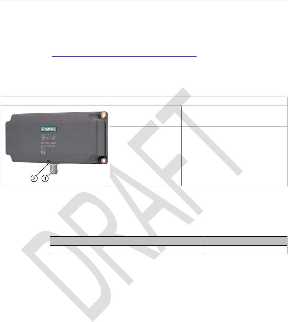
SIMATIC RF380R
Characteristics
Design ① RS-232 or RS-422 interface
②
Status display
Area of application Identification tasks on assembly lines in
harsh industrial environments
5.6.2
RF380R ordering data
Table 5- 25 RF380R ordering data
Article number
RF380R with RS-232/RS-422 interface (3964R) 6GT2801-3AB10
5.6.3
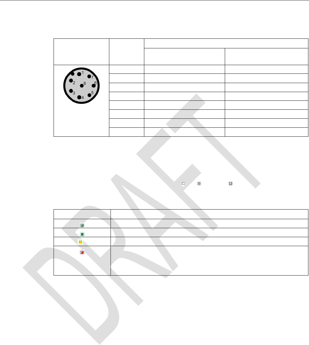
Pin assignment of RF380R RS-232/RS-422 interface
You can connect the RF380R reader to a higher-level system via the internal RS-422
interface or via the RS-232 interface. After connection, the interface module automatically
detects which interface has been used.
Readers
5.6 SIMATIC RF380R
SIMATIC RF300
System Manual, 07/2016, C79000-G8976-C345-0x 167
Note correct assignment of the pins here:
Pin
Pin
Device end
8-pin M12
Assignment
RS-232
RS-422
1
+ 24 V
+ 24 V
2 RXD - Transmit
3
0 V
0 V
4
TXD
+ Transmit
5
not used
+ Receive
6
not used
- Receive
7
not used
not used
8
Ground (shield)
Ground (shield)
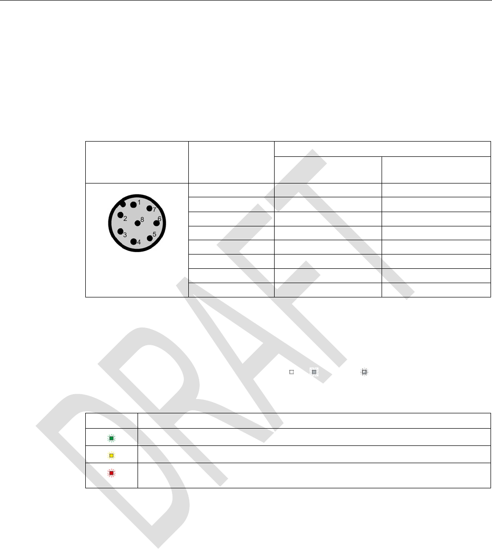
5.6.4
LED operating display
The operational statuses of the reader are displayed by the LEDs. The LED can adopt the
colors green, red or yellow and the statuses off , on , flashing :
Table 5- 26 LED operating display on the reader
Color
Meaning
Operating voltage present, reader not initialized or antenna switched off
Operating voltage present, reader initialized and antenna switched on
1)
Transponder present
Error has occurred, the type of flashing corresponds to the error code in the
table in the section Error codes. The optical error display is only reset if the
corresponding reset para
meter ("option_1", see FC 45 / FB 45 documentation,
section Input parameters) is set.
1) Only in the "with presence" mode.
5.6.5
Ensuring reliable data exchange
The "center point" of the transponder must be situated within the transmission window.
Readers
5.6 SIMATIC RF380R
SIMATIC RF300
168 System Manual, 07/2016, C79000-G8976-C345-0x
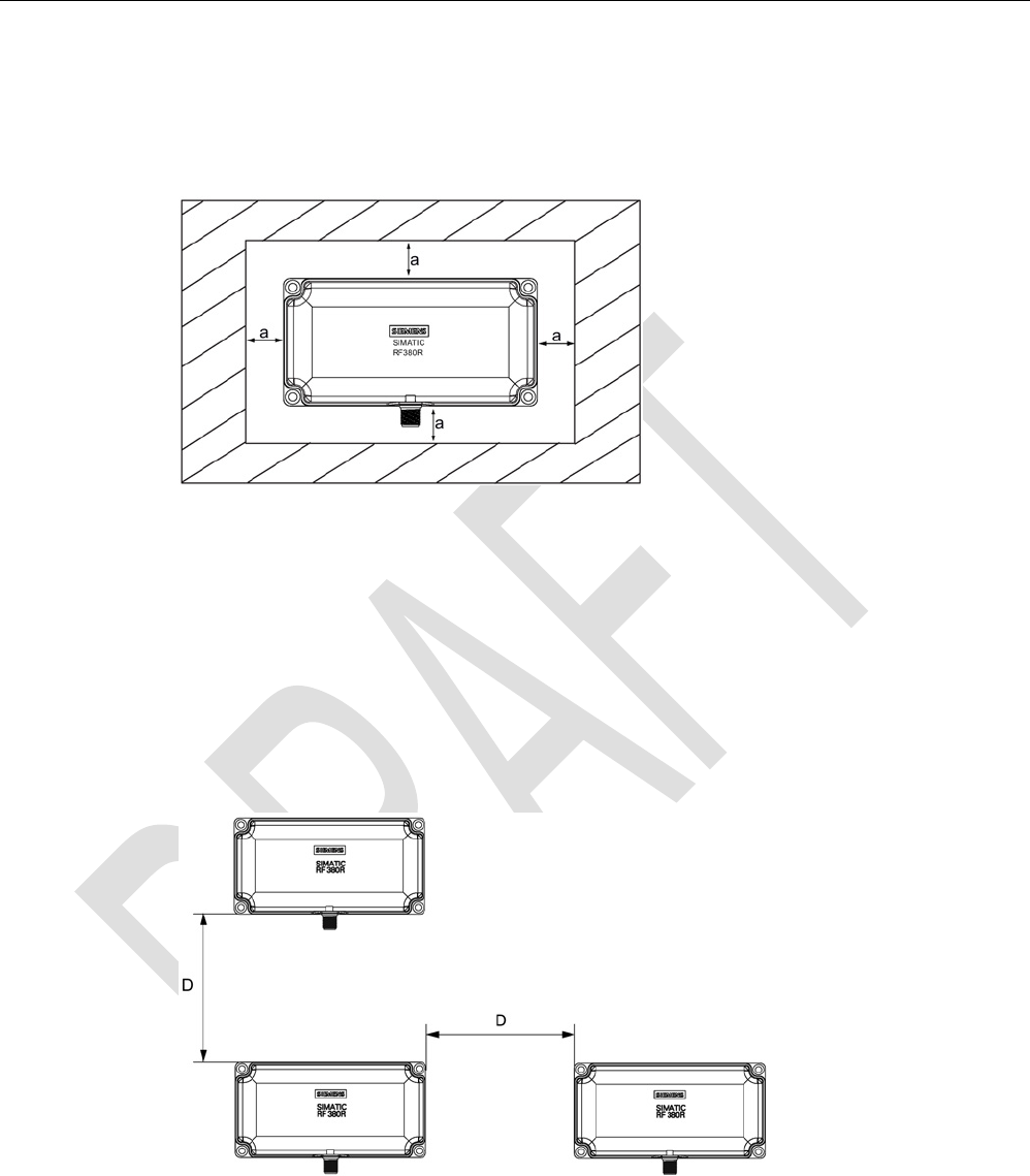
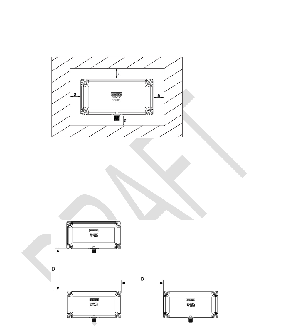
5.6.6
Metal-free area
The RF380R can be flush-mounted in metal. Please allow for a possible reduction in the field
data values.
Figure 5-23 Metal-free area for RF380R
To avoid any impact on the field data, the distance a should be ≥ 20 mm.
5.6.7
Minimum distance between RF380R readers
RF380R side by side
D
≥ 400 mm (with 2 readers)
D
≥ 500 mm (with more than 2 readers)
Figure 5-24 Minimum distance between RF380R readers
Readers
5.6 SIMATIC RF380R
SIMATIC RF300
System Manual, 07/2016, C79000-G8976-C345-0x 169
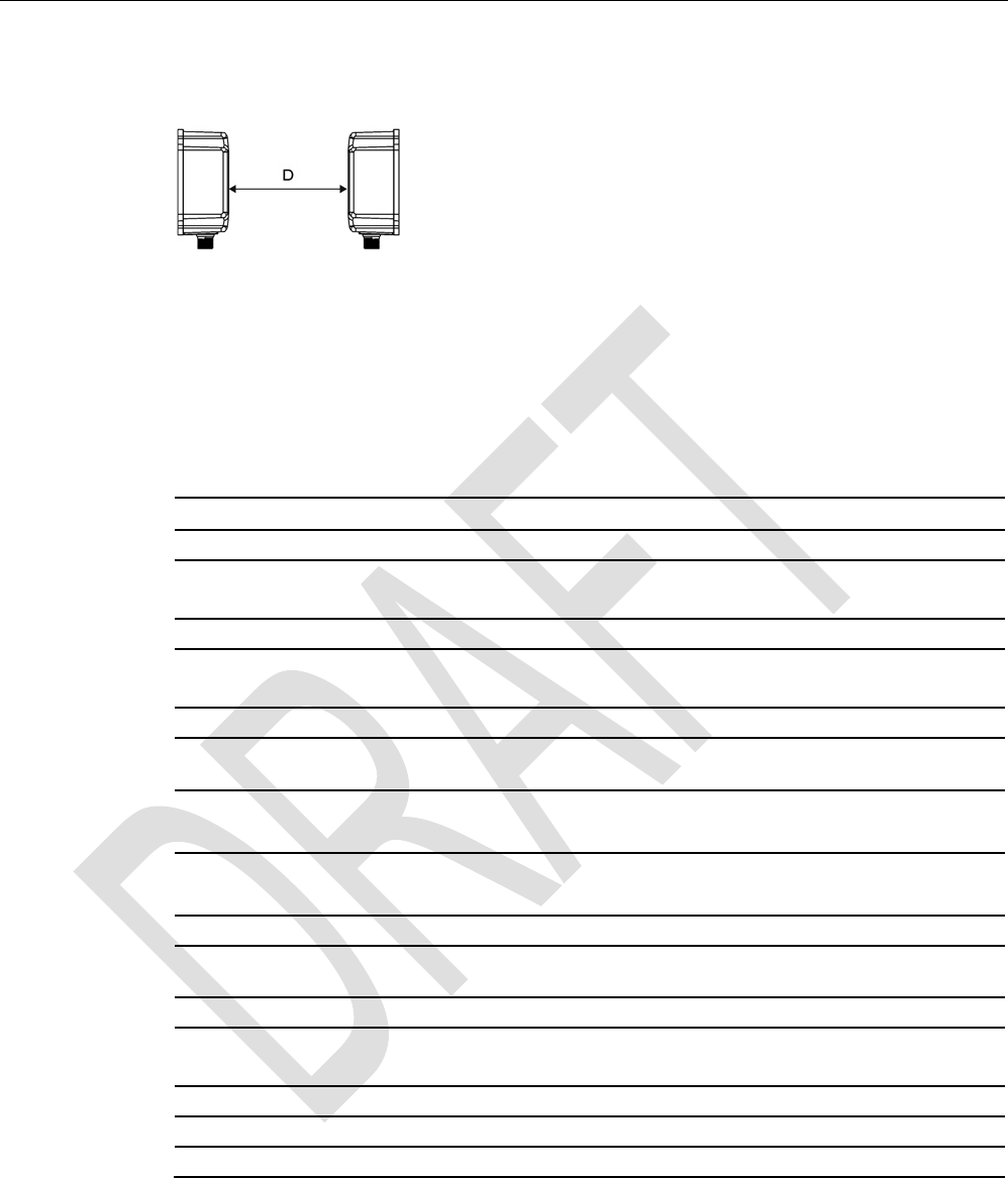
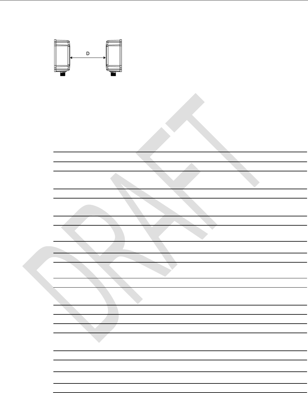
RF380R face-to-face
D
≥ 800 mm
Figure 5-25 Face-to-face distance between two RF380R
5.6.8
Technical specifications
Table 5- 27 Technical specifications of the RF380R reader
6GT2801-3AB10
Product type designation
SIMATIC RF380R
Radio frequencies
Operating frequency, rated value
13.56 MHz
Electrical data
Maximum range
200 mm
Maximum data transmission speed
reader ↔ transponder
RF300 transponder ISO transponder
• Read • approx. 8000
bytes/s
• approx. 1500
bytes/s
• Write • approx. 8000
bytes/s
• approx. 1500
bytes/s
Transmission speed
19.2, 57.6, 115.2 kBd
Read/write distances of the reader See section "Field data for transponders, readers
and antennas (Page 48)."
MTBF (Mean Time Between Failures)
109 years
Interfaces
Electrical connector design
M12, 8-pin
Standard for interfaces for communication
RS-232/RS-422 (3964R protocol)
Antenna
integrated

Readers
5.6 SIMATIC RF380R
SIMATIC RF300
170 System Manual, 07/2016, C79000-G8976-C345-0x
6GT2801-3AB10
Mechanical specifications
Housing
• Material • Plastic PA 12
• Color • Anthracite
Recommended distance to metal
0 mm
Supply voltage, current consumption, power loss
Supply voltage
24 VDC
Typical current consumption
160 mA
Permitted ambient conditions
Ambient temperature
• During operation • -25 to +70 ℃
• During transportation and storage • -40 to +85 ℃
Degree of protection to EN 60529
IP67
Shock-resistant to EN 60721-3-7, Class 7 M3
50 g
Vibration-resistant to EN 60721-3-7, Class 7 M3
20 g
Torsion and bending load
Not permitted
Design, dimensions and weight
Dimensions (L x W x H)
160 x 80 x 41 mm
Weight
600 g
Type of mounting 4 x M5 screws;
1.5 Nm
Cable length for RS-422 interface, maximum
RS-422
RS-232
1000 m 30 m
LED display design 3-color LED
Standards, specifications, approvals
Proof of suitability Radio in accordance with R&TTE directives EN
300330,
EN 301489, CE, FCC, UL/CSA,
Ex: II 3G Ex nC IIB T5

Readers
5.6 SIMATIC RF380R
SIMATIC RF300
System Manual, 07/2016, C79000-G8976-C345-0x 171
5.6.9
Approvals
FCC information
Siemens SIMATIC RF380R (MLFB 6GT2801-3AA10); FCC ID NXW-RF380R
Siemens SIMATIC RF380R (MLFB 6GT2801-3AB10); FCC ID NXW-RF380R01
This device complies with part 15 of the FCC rules. Operation is subject to the following two
conditions:
(1) This device may not cause harmful interference, and
(2) this device must accept any interference received, including interference that may cause
undesired operation.
Caution
Any changes or modifications not expressly approved by the party responsible for
compliance could void the user's authority to operate the equipment.
Note
This equipment has been tested and found to comply with the limits for a Class A digital
device, pursuant to part 15 of the FCC Rules.
These limits are designed to provide reasonable protection against harmful interference
when the equipment is operated in a commercial environment. This equipment generates,
uses, and can radiate radio frequency energy and, if not installed and used in accordance
with the instruction manual, may cause harmful interference to radio communications.
Operation of this equipment in a residential area is likely to cause harmful interference in
which case the user will be required to correct the interference at his own expense.
IC information
This device complies with Industry Canada licence-exempt RSS standard(s). Operation is
subject to the following two conditions:
(1) This device may not cause interference, and
(2) this device must accept any interference, including interference that may cause
undesired operation of the device.
Le présent appareil est conforme aux CNR d`Industrie Canada applicables aux appareils
radio exempts de licence. L`exploitation est autorisée aux deux conditions suivantes :
(1) L`appareil ne doit pas produire de brouillage, et
(2) l'utilisateur de l`appareil doit accepter tout brouillage radioélectrique subi, même si le
brouillage est susceptible d`en compromettre le fonctionnement.
Readers
5.6 SIMATIC RF380R
SIMATIC RF300
172 System Manual, 07/2016, C79000-G8976-C345-0x
5.6.10
Use of the reader in hazardous areas
The TÜV SÜD Automotive GmbH as approved test center as well as the TÜV SÜD Product
Service GmbH as certification center, identification number 0123, as per Article 9 of the
Directive of the European Council of 23 March 1994 (94/9/EC), has confirmed the
compliance with the essential health and safety requirements relating to the design and
construction of equipment and protective systems intended for use in hazardous areas as
per Annex II of the Directive. The essential health and safety requirements are satisfied in
accordance with the following standards:
Document
Title
EN 60079-0: 2006
Electrical equipment for hazardous gas atmospheres -
Part 0: General requirements
EN 60079-15: 2005 Electrical equipment for hazardous gas atmospheres -
Part 15: Design, testing and identification of electrical equipment
with type of protection "n"
DIN VDE 0848-5: 2001
(in parts)
Safety in electrical, magnetic and electromagnetic fields -
Part 5: Explosion protection
ZLS SK 107.1
Central office of the states for safety; test components
Identification
The identification of the electrical equipment as an enclosed unit is:
II 3G Ex nC IIB T5
-25 °C to +70 °C
Um=30Vdc
The equipment is assigned the following references:
XXXYYYZZZ
[= serial number, is assigned during production]
TPS 09 ATEX 1 459 X
[= certificate number]
"No use of the equipment in the vicinity of processes generating high charges"
"Do not disconnect plug on load"
Readers
5.6 SIMATIC RF380R
SIMATIC RF300
System Manual, 07/2016, C79000-G8976-C345-0x 173
5.6.11
Use of the reader in hazardous areas for gases
Temperature class delineation for gases
The temperature class of the reader for hazardous areas depends on the ambient
temperature range:
Ambient temperature range
Temperature class
-25 °C to +70 °C
T5
WARNING
Ignitions of gas-air mixtures
When using the RF380R reader, check to ensure that the temperature class is observed in
respect of the requirements of the area of application
Non-compliance with the permitted temperature ranges while using the reader can lead to
ignitions of gas-air mixtures.
5.6.12
Installation and operating conditions for the hazardous area
a) The connector on the RF380R must be grounded via its supply line.
b) Use of the equipment in the vicinity of processes generating high charges is not allowed.
c) The plug of the RF380R must not be disconnected in a hazardous atmosphere or under
load.
d) The supply line for the RF380R is not part of this certificate. The supply line must exhibit a
sufficient temperature resistance.
e) The equipment must be mechanically protected when installed.
Readers
5.6 SIMATIC RF380R
SIMATIC RF300
174 System Manual, 07/2016, C79000-G8976-C345-0x
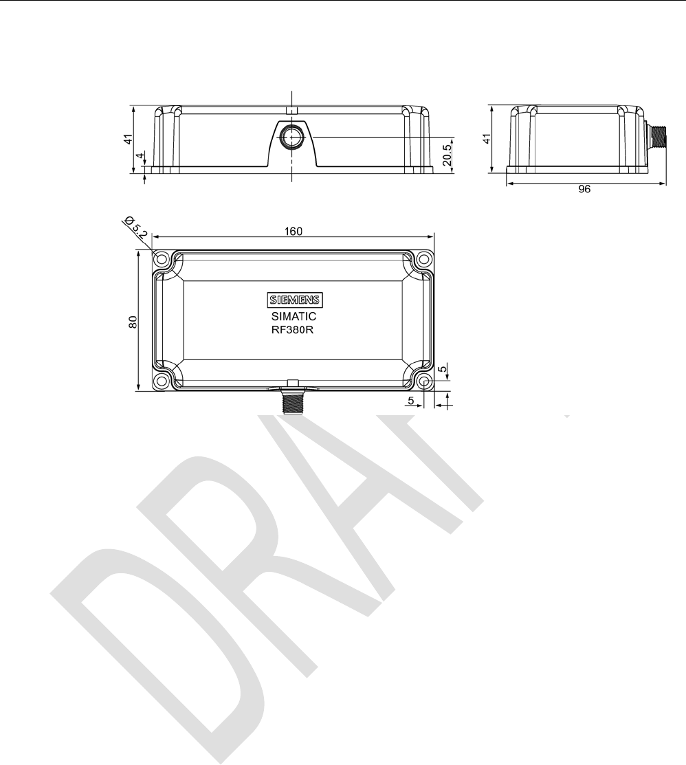
5.6.13
Dimension drawing
Figure 5-26 Dimension drawing RF380R
Dimensions in mm
Readers
5.7 SIMATIC RF380R with Scanmode
SIMATIC RF300
System Manual, 07/2016, C79000-G8976-C345-0x 175
5.7
SIMATIC RF380R with Scanmode
You will find detailed information on the SIMATIC RF382R with Scanmode on the Industry
Online Support - SIMATIC RF380R with Scanmode
(https://support.industry.siemens.com/cs/ww/en/ps/15037).
5.7.1
Features
RF380R Scanmode
Characteristics
Design ① RS232 or RS422 interface
②
Status display
Field of application Identification tasks on assembly lines in
harsh industrial environments
5.7.2
Ordering data for RF380R with Scanmode
Table 5- 28 Ordering data RF380R Scanmode
Product
Article number
RF380R Scanmode 6GT2801-3AB20-0AX1
Readers
5.7 SIMATIC RF380R with Scanmode
SIMATIC RF300
176 System Manual, 07/2016, C79000-G8976-C345-0x
5.7.3
Pin assignment RF380R Scanmode RS-232 interface
You can connect the RF380R Scanmode reader via the internal RS-232/RS-422 interface to
a higher-level system. (See section "Basic rules (Page 101)") Make sure that the pin
assignment is correct. In the factory settings, the reader is set to RS-232. Siemens can
change the interface to RS-422.
Table 5- 29 Connector and reader pin assignment
Pin
Pin
Device end 8-pin
M12
Assignment
RS-232
RS-422
1
+ 24 V
+ 24 V
2 RXD - Transmit
3
0 V
0 V
4
TXD
+ Transmit
5
not used
+ Receive
6
not used
- Receive
7
not used
not used
8
Ground (shield)
Ground (shield)
5.7.4
LED operating display
The operational statuses of the reader are displayed by the LEDs. The LED can adopt the
colors green, red or yellow and the statuses off , on , flashing :
Table 5- 30 LED operating display on the reader
Color
Meaning
Operating voltage present, reader ready for operation
Transponder present
Red LED for error display is activated permanently if correct operation of the reader
cannot be guaranteed (e. g. faulty start, checksum error during operation).
5.7.5
Ensuring reliable data exchange
The "center point" of the transponder must be situated within the transmission window.
Readers
5.7 SIMATIC RF380R with Scanmode
SIMATIC RF300
System Manual, 07/2016, C79000-G8976-C345-0x 177
5.7.6
Metal-free area
The RF380R can be flush-mounted in metal. Please allow for a possible reduction in the field
data values.
Figure 5-27 Metal-free area for RF380R
To avoid any impact on the field data, the distance a should be ≥ 20 mm.
5.7.7
Minimum distance between several RF380R Scanmode readers
RF380R side by side
D
≥ 400 mm (with 2 readers)
D
≥ 500 mm (with more than 2 readers)
Figure 5-28 Minimum distance between RF380R readers
Readers
5.7 SIMATIC RF380R with Scanmode
SIMATIC RF300
178 System Manual, 07/2016, C79000-G8976-C345-0x
RF380R face-to-face
D
≥ 800 mm
Figure 5-29 Face-to-face distance between two RF380R
5.7.8
Technical specifications
Table 5- 31 Technical specifications of the RF380R Scanmode reader
6GT2801-3AB20-0AX1
Product type designation
SIMATIC RF380R Scanmode
Radio frequencies
Operating frequency, rated value
13.56 MHz
Electrical data
Maximum range
200 mm
Maximum data transmission speed
reader ↔ transponder
RF300 transponder ISO transponder
• Read approx. 8000 bytes/s approx. 1500 bytes/s
Transmission speed
9.6, 19.2, 38.4, 57, 115.2 kBd
Read distances of the reader see section "Field data for transponders, readers
and antennas (Page 48)"
MTBF (Mean Time Between Failures)
109 years
Interfaces
Electrical connector design
M12, 8-pin
Standard for interfaces for communication
RS-232 / RS-422
Antenna
integrated
Mechanical specifications
Enclosure
• Material • Plastic PA 12
• Color • Anthracite
Recommended distance to metal
0 mm

Readers
5.7 SIMATIC RF380R with Scanmode
SIMATIC RF300
System Manual, 07/2016, C79000-G8976-C345-0x 179
6GT2801-3AB20-0AX1
Supply voltage, current consumption, power loss
Supply voltage
24 VDC
Typical current consumption
160 mA
Permitted environmental conditions
Ambient temperature
• During operation -25 to +70 °C
• Transport and storage -40 to +85 °C
Degree of protection to EN 60529
IP67
Shock-resistant to EN 60721-3-7, Class 7 M3
50 g
Vibration-resistant to EN 60721-3-7, Class 7 M3
20 g
Torsion and bending load
Not permitted
Design, dimensions and weights
Dimensions (L x W x H)
160 x 80 x 41 (without M12 device connector)
Weight
Approx. 600 g
Type of mounting 4 x M5 screws;
1.5 Nm
Cable length for RS-422 interface, maximum
RS-422
RS-232
1000 m
30 m
LED display design
3-color LED
Standards, specifications, approvals
Proof of suitability Radio to R&TTE directives EN 300330,
EN 301489, CE, FCC, UL/CSA

Readers
5.7 SIMATIC RF380R with Scanmode
SIMATIC RF300
180 System Manual, 07/2016, C79000-G8976-C345-0x
5.7.9
Approvals
FCC information
Siemens SIMATIC RF380R (MLFB 6GT2801-3AB20-0AX1); FCC ID NXW-RF380R01
This device complies with part 15 of the FCC rules. Operation is subject to the following two
conditions:
(1) This device may not cause harmful interference, and
(2) this device must accept any interference received, including interference that may cause
undesired operation.
Caution
Any changes or modifications not expressly approved by the party responsible for
compliance could void the user's authority to operate the equipment.
Note
This equipment has been tested and found to comply with the limits for a Class A digital
device, pursuant to part 15 of the FCC Rules.
These limits are designed to provide reasonable protection against harmful interference
when the equipment is operated in a commercial environment. This equipment generates,
uses, and can radiate radio frequency energy and, if not installed and used in accordance
with the instruction manual, may cause harmful interference to radio communications.
Operation of this equipment in a residential area is likely to cause harmful interference in
which case the user will be required to correct the interference at his own expense.
IC information
This device complies with Industry Canada licence-exempt RSS standard(s). Operation is
subject to the following two conditions:
(1) This device may not cause interference, and
(2) this device must accept any interference, including interference that may cause
undesired operation of the device.
Le présent appareil est conforme aux CNR d`Industrie Canada applicables aux appareils
radio exempts de licence. L`exploitation est autorisée aux deux conditions suivantes :
(1) L`appareil ne doit pas produire de brouillage, et
(2) l'utilisateur de l`appareil doit accepter tout brouillage radioélectrique subi, même si le
brouillage est susceptible d`en compromettre le fonctionnement.
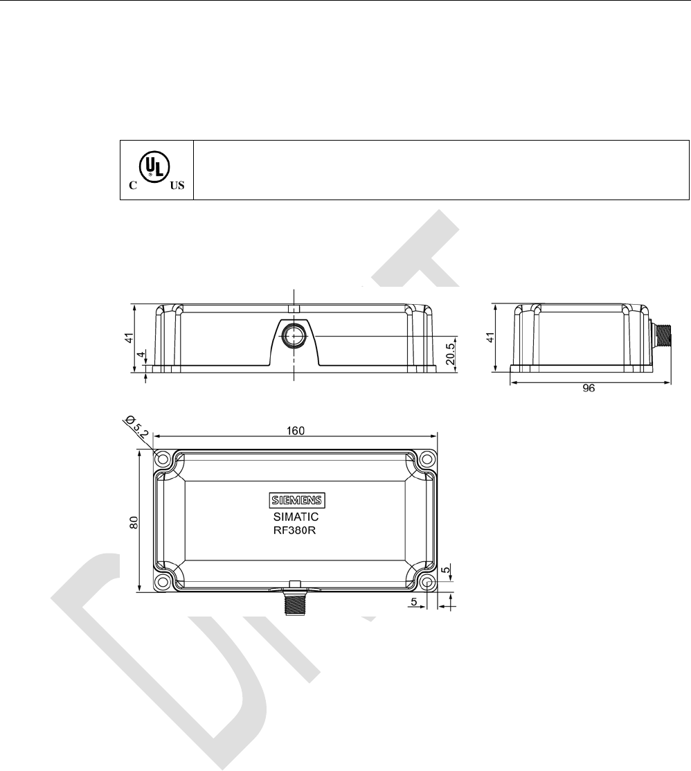
Readers
5.7 SIMATIC RF380R with Scanmode
SIMATIC RF300
System Manual, 07/2016, C79000-G8976-C345-0x 181
5.7.10
Certificates and Approvals
Certificates for USA and Canada
Underwriters Laboratories (UL) acc. to standard UL 60950, Report E11 5352 and Ca-
nadian standard C22.2 No. 60950 (I.T.E) or acc. to UL508 and C22.2 No. 142
(IND.CONT.EQ)
5.7.11
Dimension drawing
Figure 5-30 Dimension drawing RF380R
Dimensions in mm
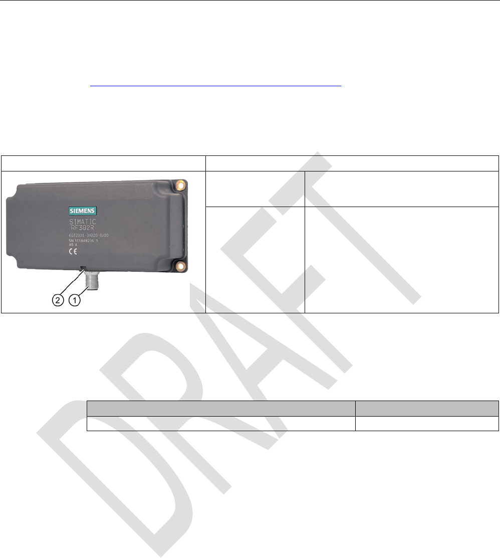
Readers
5.8 SIMATIC RF382R with Scanmode
SIMATIC RF300
182 System Manual, 07/2016, C79000-G8976-C345-0x
5.8
SIMATIC RF382R with Scanmode
You will find detailed information on the SIMATIC RF382R with Scanmode on the Internet
(https://support.industry.siemens.com/cs/ww/en/ps/15038).
5.8.1
Characteristics
RF382R Scanmode
Characteristics
Design ① RS-232 or RS-422 interface
②
Status display
Operating range Suitable for high speeds, e.g. in
• Suspension conveyor systems
• Assembly lines
• Production
• Order picking
5.8.2
RF382R with Scanmode ordering data
Table 5- 32 RF382R Scanmode ordering data
Article number
RF382R Scanmode
6GT2801-3AB20-0AX0
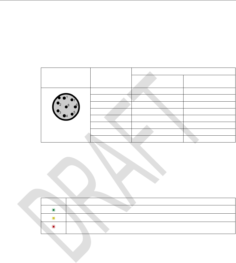
Readers
5.8 SIMATIC RF382R with Scanmode
SIMATIC RF300
System Manual, 07/2016, C79000-G8976-C345-0x 183
5.8.3
Pin assignment RF382R Scanmode RS232 interface
You can connect the RF382R Scanmode reader via the internal RS-232/RS-422 interface or
via a higher-level system. (See section "Basic rules (Page 101)") Make sure that the pin
assignment is correct. In the factory settings, the reader is set to RS-232. Siemens can
change the interface to RS-422.
Table 5- 33 Connector and reader pin assignment
Pin
Pin
Device end 8-pin
M12
Assignment
RS-232
RS-422
1
+ 24 V
+ 24 V
2 RXD - Transmit
3
0 V
0 V
4
TXD
+ Transmit
5
not used
+ Receive
6
not used
- Receive
7
not used
not used
8
Ground (shield)
Ground (shield)
5.8.4
LED operating display
The operational statuses of the reader are displayed by the LEDs. The LED can adopt the
colors green, red or yellow and the statuses off , on , flashing :
Table 5- 34 LED operating display on the reader
Color
Meaning
Operating voltage present, reader ready for operation
Transponder present
Red LED for error display is activated permanently if correct operation of the reader
cannot be guaranteed (e. g. faulty start, checksum error during operation).
5.8.5
Ensuring reliable data exchange
The "center point" of the transponder must be situated within the transmission window.
5.8.6
Mounting on metal
The RF382R can be mounted directly on metal. Flush mounting on metal is not permitted.
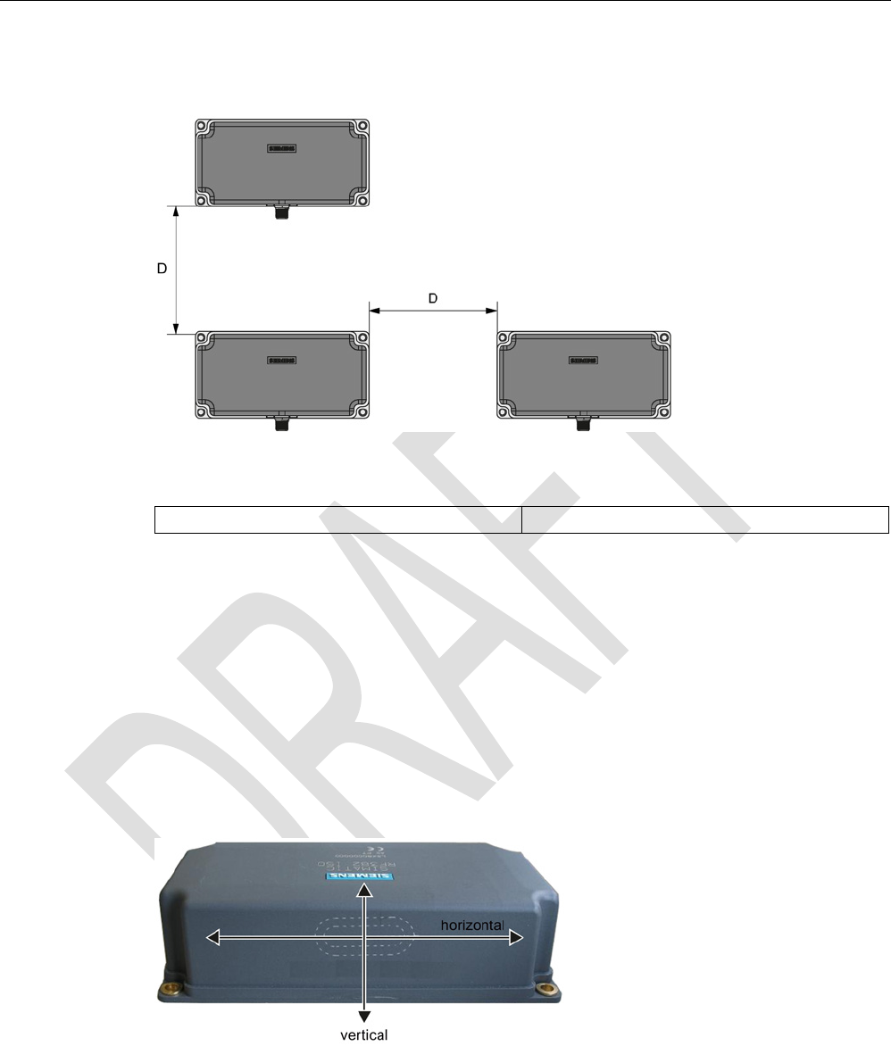
Readers
5.8 SIMATIC RF382R with Scanmode
SIMATIC RF300
184 System Manual, 07/2016, C79000-G8976-C345-0x
5.8.7
Minimum distance between several RF382R Scanmode readers
Figure 5-31 Minimum distance between several RF382R Scanmode readers
Minimum distance D from RF382R to RF382R
D ≥ 200 mm
5.8.8
Transmission window
Orientation of fields of the SIMATIC RF382R Scanmode
For many applications it may be best to operate the reader so that the tags move from left to
right (or from right to left) at a certain distance in front of the narrow edge of the reader. With
this direction of movement, the horizontal reader field is used, see figure below.
You also have the option of moving the tags up and down (or down and up) past the narrow
edge of the reader. With this direction of movement, uses the vertical reader field is used.
Figure 5-32 Definition of horizontal and vertical reader field
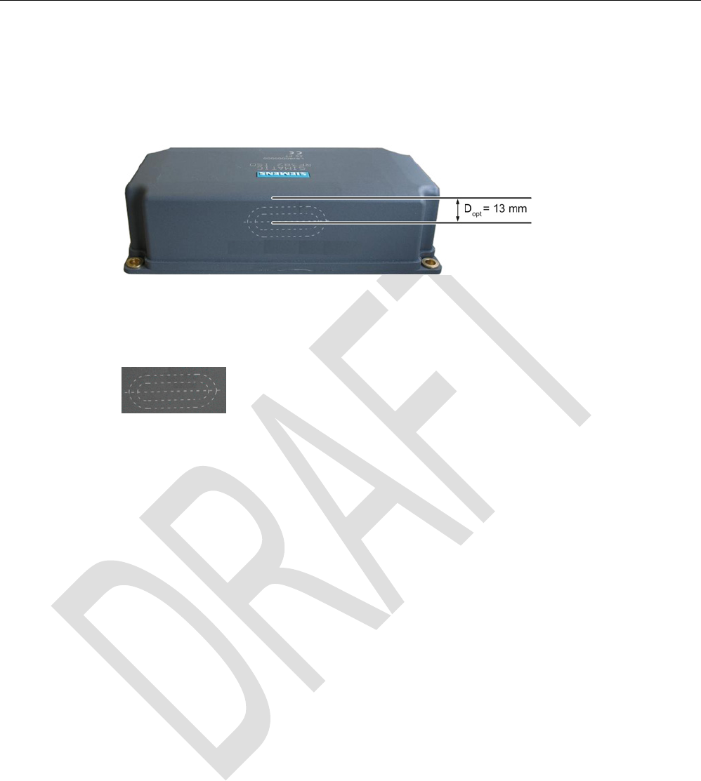
Readers
5.8 SIMATIC RF382R with Scanmode
SIMATIC RF300
System Manual, 07/2016, C79000-G8976-C345-0x 185
Maximum field strength
The reader creates the maximum field approximately 13 mm below the upper reader edge.
For the largest possible reading range the tags you want to read should move in this range.
This applies regardless of whether the horizontal or the vertical field is used.
Figure 5-33 Line of maximum magnetic field strength
The area of the maximum field strength and, therefore, the maximum range is identified by a
laser icon:
Figure 5-34 Laser labeling
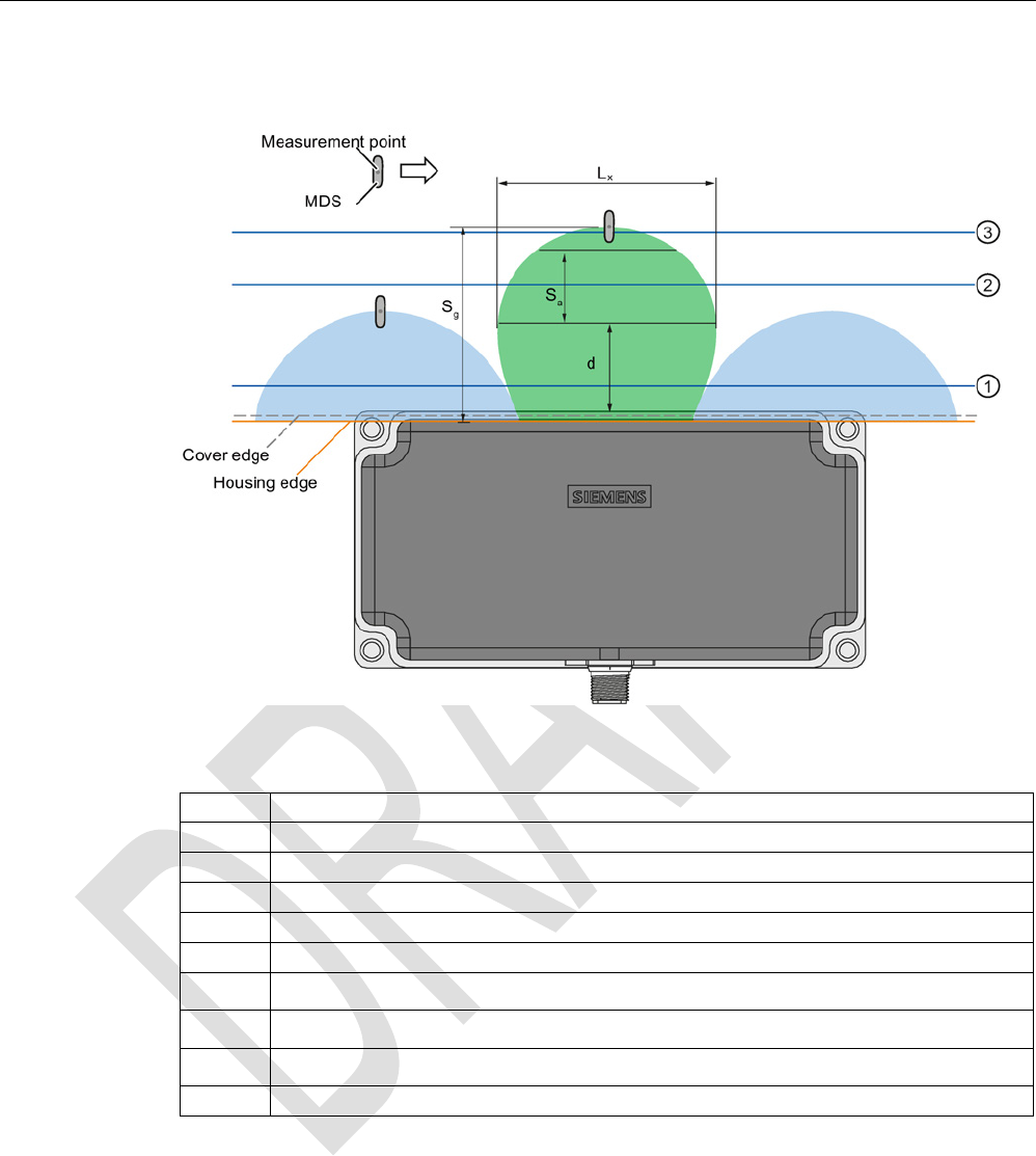
Readers
5.8 SIMATIC RF382R with Scanmode
SIMATIC RF300
186 System Manual, 07/2016, C79000-G8976-C345-0x
Transmission window horizontal field
Figure 5-35 Distance definition horizontal field
Green
Main field (processing field)
Blue Secondary fields, horizontal field
L
x
Maximum length of the main field, horizontal field
d
Distance from the reader edge at which maximum horizontal main field length L exists
S
a
Operating range in the main field
Sg
Limit distance
①
Level 1
②
Level 2
③
Level 3
⇒
Direction of motion of the transponder
Operating range (Sa)
The operating range lies between Level ① and Level ③.
The operating range between Levels ① and ② includes secondary fields.
The recommended operating range therefore lies in the green main field between Level 2
and Level 3.
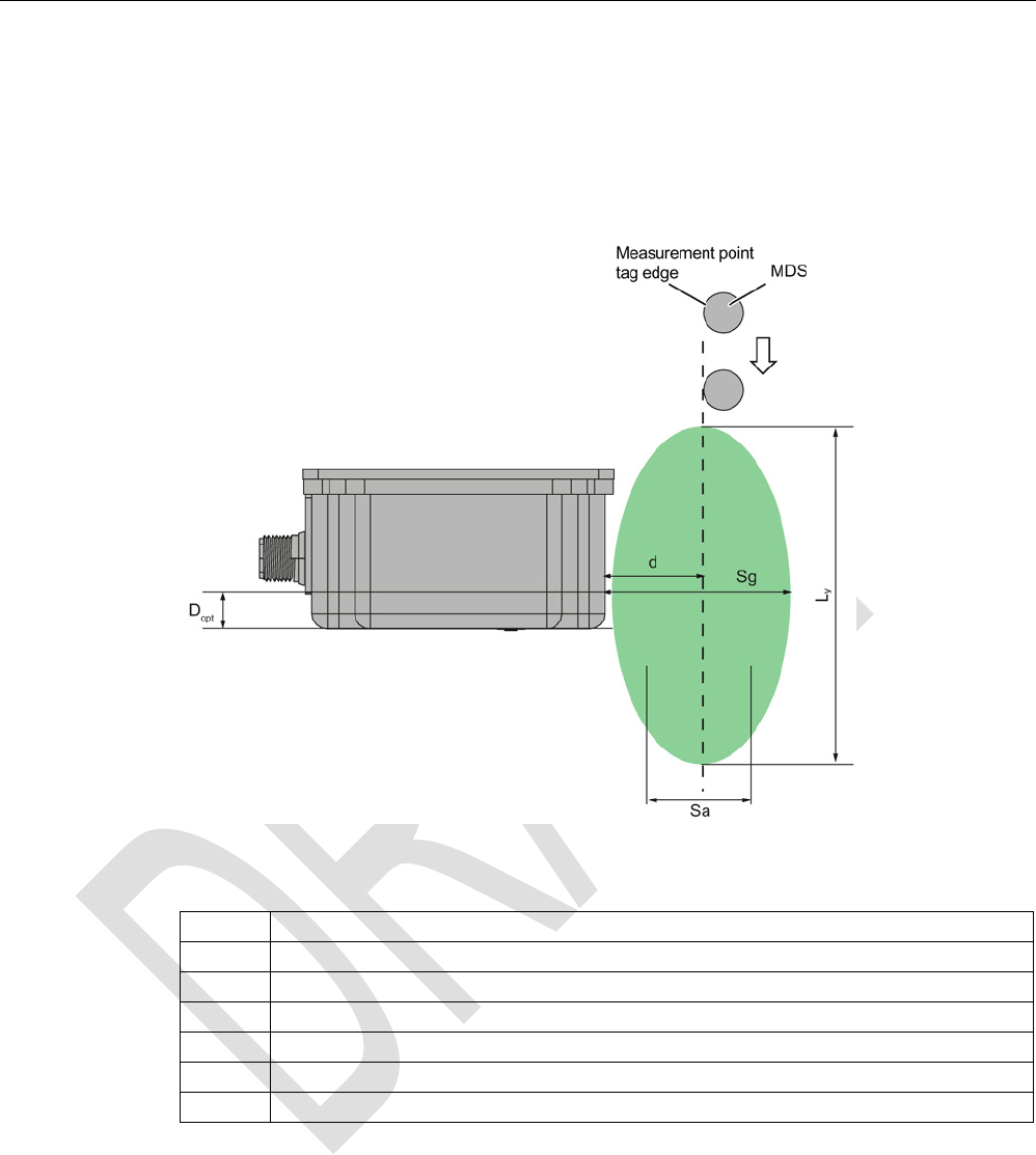
Readers
5.8 SIMATIC RF382R with Scanmode
SIMATIC RF300
System Manual, 07/2016, C79000-G8976-C345-0x 187
Limit distance (Sg)
The limit distance lies on Level ③.
Transmission window vertical field
Figure 5-36 Distance definition vertical field
Green
Main field (processing field)
Ly
Maximum length of the main field, vertical field
d
Distance from the reader edge at which maximum vertical main field length L
y
exists
Sa
Operating range in the main field
S
g
Limit distance
D
opt
= 13 mm
⇓ Direction of motion of the transponder

Readers
5.8 SIMATIC RF382R with Scanmode
SIMATIC RF300
188 System Manual, 07/2016, C79000-G8976-C345-0x
5.8.9
Technical specifications
Table 5- 35 Technical specifications of the RF382R reader with Scanmode
6GT2801-3AB20-0AX0
Product type designation
SIMATIC RF382R Scanmode
Radio frequencies
Operating frequency, rated value
13.56 MHz
Electrical data
Maximum range
75 mm
Maximum data transmission speed
reader ↔ transponder
ISO transponder
• Read • approx. 1500 bytes/s
Transmission speed
19.2, 57.6, 115.2 kBd
Read/write distances of the reader See section "Field data for transponders, readers
and antennas (Page 48)."
MTBF (Mean Time Between Failures)
115 years
Interfaces
Electrical connector design
M12, 8-pin
Standard for interfaces for communication RS-232 (factory setting, can be changed to RS-
422)
Antenna
integrated
Mechanical specifications
Housing
• Material • Plastic PA 12
• Color • Anthracite
Recommended distance to metal 0 mm
Supply voltage, current consumption, power loss
Supply voltage 24 VDC
Typical current consumption
140 mA

Readers
5.8 SIMATIC RF382R with Scanmode
SIMATIC RF300
System Manual, 07/2016, C79000-G8976-C345-0x 189
6GT2801-3AB20-0AX0
Permitted ambient conditions
Ambient temperature
• During operation • -25 to +70 ℃
• During transportation and storage • -40 to +85 ℃
Degree of protection to EN 60529
IP67
Shock-resistant to EN 60721-3-7, Class 7 M3
50 g
Vibration-resistant to EN 60721-3-7, Class 7 M3
20 g
Torsion and bending load
Not permitted
Design, dimensions and weight
Dimensions (L x W x H)
160 x 80 x 41 mm
Weight
550 g
Type of mounting 4 x M5 screws;
1.5 Nm
Cable length for RS-422 interface, maximum
RS-422
RS-232
1000 m
30 m
LED display design
3-color LED
Standards, specifications, approvals
Proof of suitability Radio to R&TTE directives EN 300330,
EN 301489, CE, FCC, UL/CSA
5.8.10
Approvals
FCC information
Siemens SIMATIC RF382R (MLFB 6GT2801-3AB20-0AX0); FCC ID NXW-RF382R
This device complies with part 15 of the FCC rules. Operation is subject to the following two
conditions:
(1) This device may not cause harmful interference, and
(2) this device must accept any interference received, including interference that may cause
undesired operation.
Caution
Any changes or modifications not expressly approved by the party responsible for
compliance could void the user's authority to operate the equipment.
Readers
5.8 SIMATIC RF382R with Scanmode
SIMATIC RF300
190 System Manual, 07/2016, C79000-G8976-C345-0x
Note
This equipment has been tested and found to comply with the limits for a Class A digital
device, pursuant to part 15 of the FCC Rules.
These limits are designed to provide reasonable protection against harmful interference
when the equipment is operated in a commercial environment. This equipment generates,
uses, and can radiate radio frequency energy and, if not installed and used in accordance
with the instruction manual, may cause harmful interference to radio communications.
Operation of this equipment in a residential area is likely to cause harmful interference in
which case the user will be required to correct the interference at his own expense.
IC information
This device complies with Industry Canada licence-exempt RSS standard(s). Operation is
subject to the following two conditions:
(1) This device may not cause interference, and
(2) this device must accept any interference, including interference that may cause
undesired operation of the device.
Le présent appareil est conforme aux CNR d`Industrie Canada applicables aux appareils
radio exempts de licence. L`exploitation est autorisée aux deux conditions suivantes :
(1) L`appareil ne doit pas produire de brouillage, et
(2) l'utilisateur de l`appareil doit accepter tout brouillage radioélectrique subi, même si le
brouillage est susceptible d`en compromettre le fonctionnement.
Certificates for USA and Canada
Underwriters Laboratories (UL) acc. to standard UL 60950, Report E11 5352 and Ca-
nadian standard C22.2 No. 60950 (I.T.E) or acc. to UL508 and C22.2 No. 142
(IND.CONT.EQ)
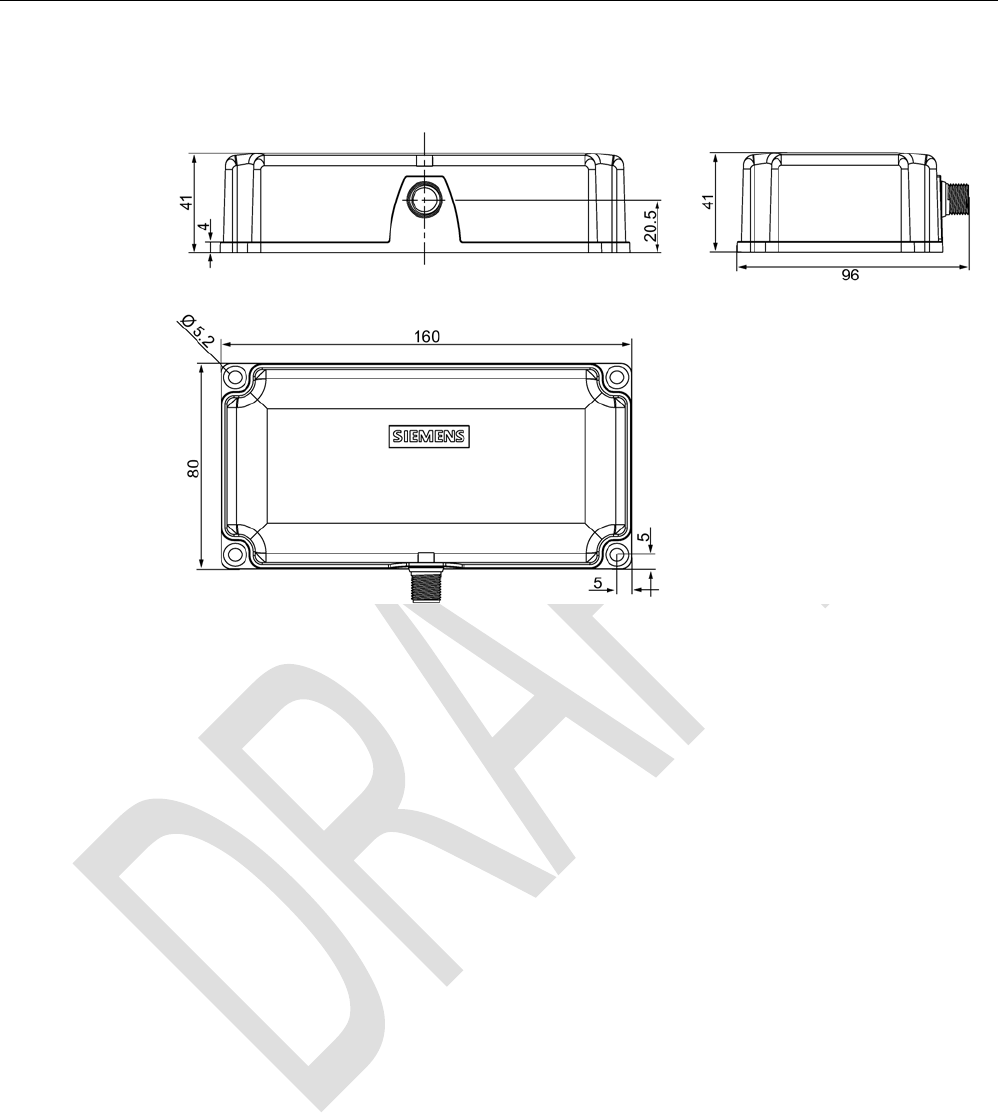
Readers
5.8 SIMATIC RF382R with Scanmode
SIMATIC RF300
System Manual, 07/2016, C79000-G8976-C345-0x 191
5.8.11
Dimensional diagram
Figure 5-37 Dimension drawing

Readers
5.8 SIMATIC RF382R with Scanmode
SIMATIC RF300
192 System Manual, 07/2016, C79000-G8976-C345-0x