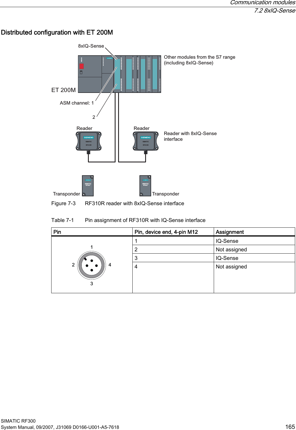
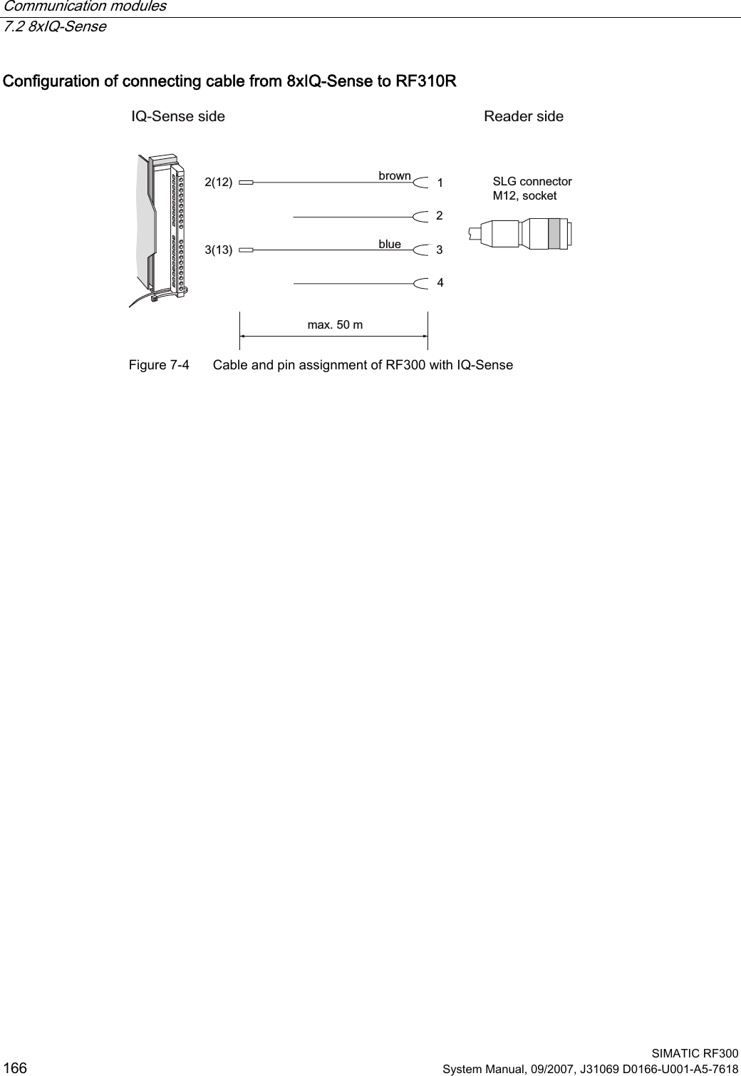
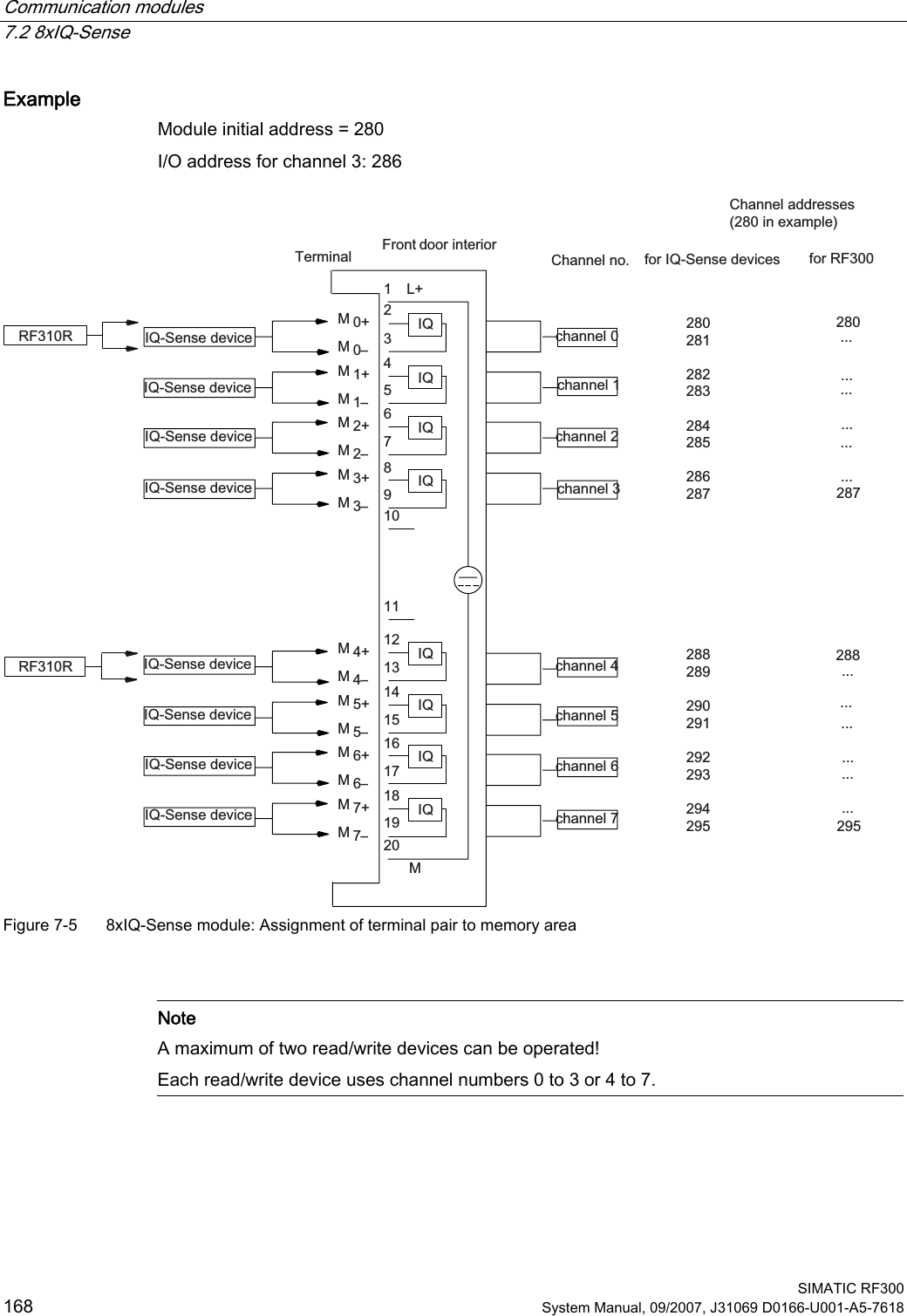
Siemens RF380R Tag Reader User Manual SIMATIC Sensors RFID systems SIMATIC RF300

Siemens AG Tag Reader SIMATIC Sensors RFID systems SIMATIC RF300

User Manual Part III
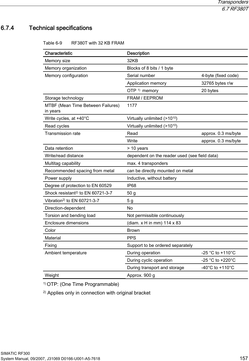
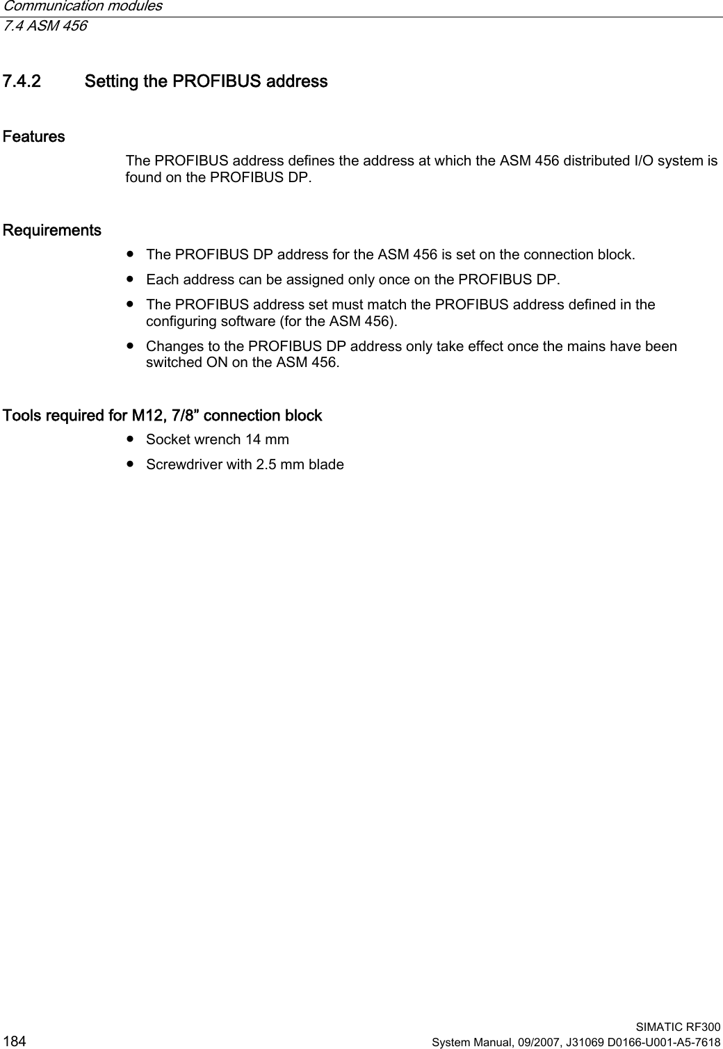
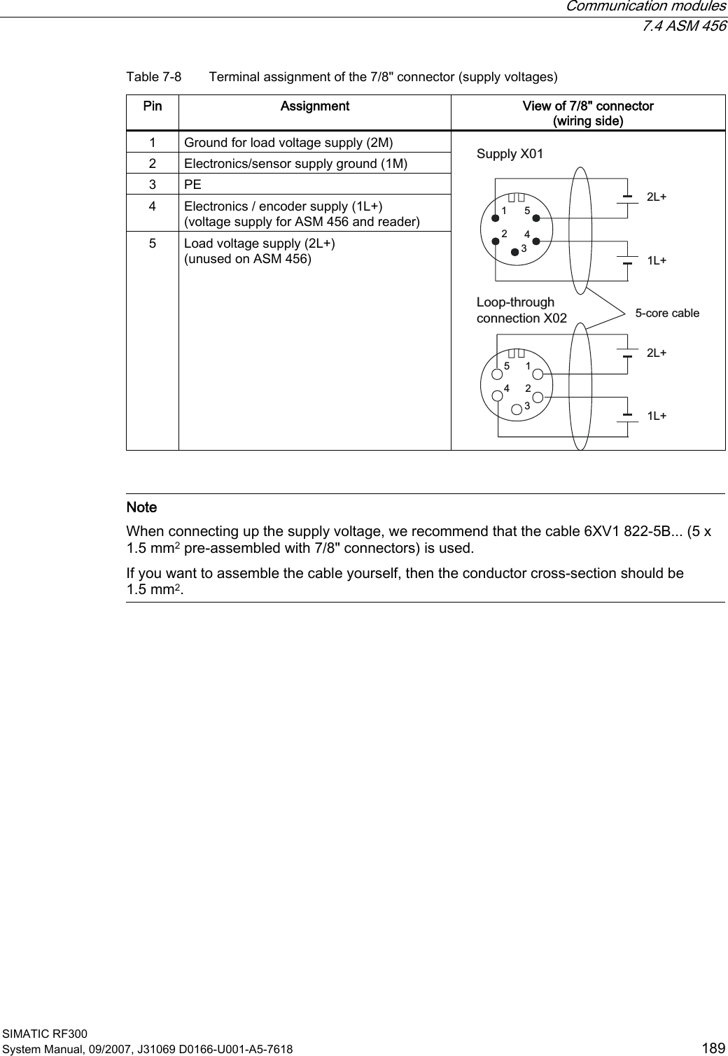
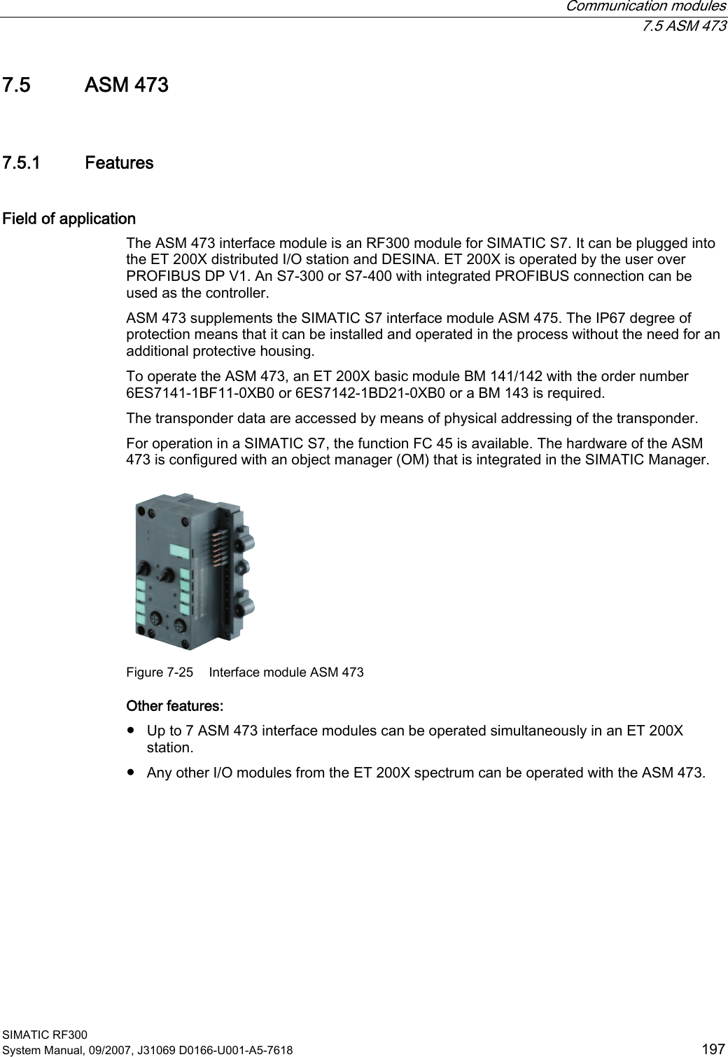
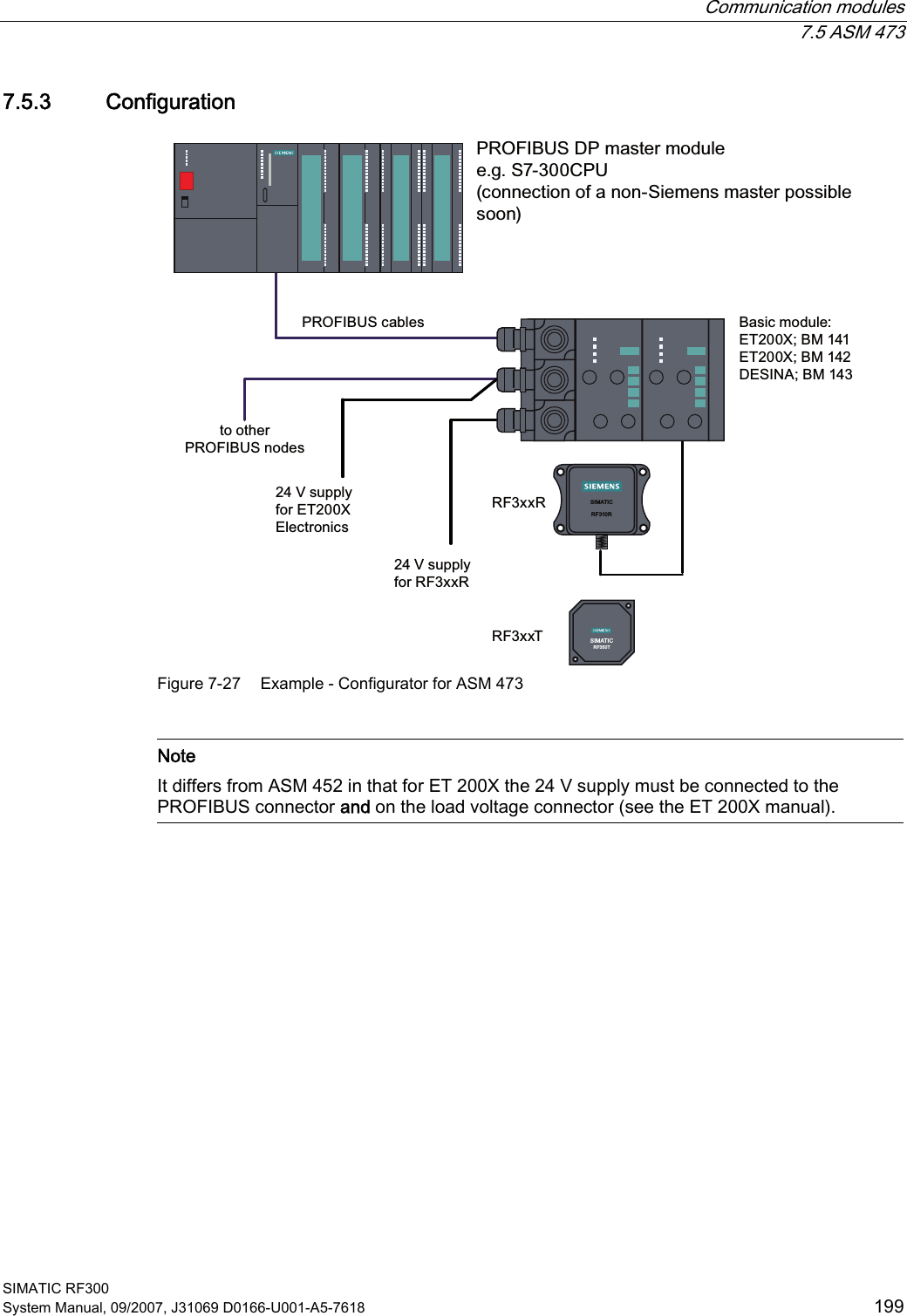
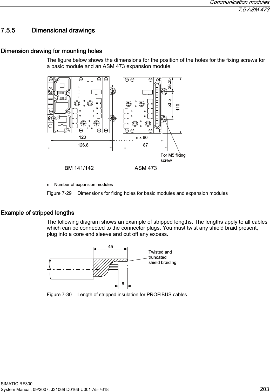
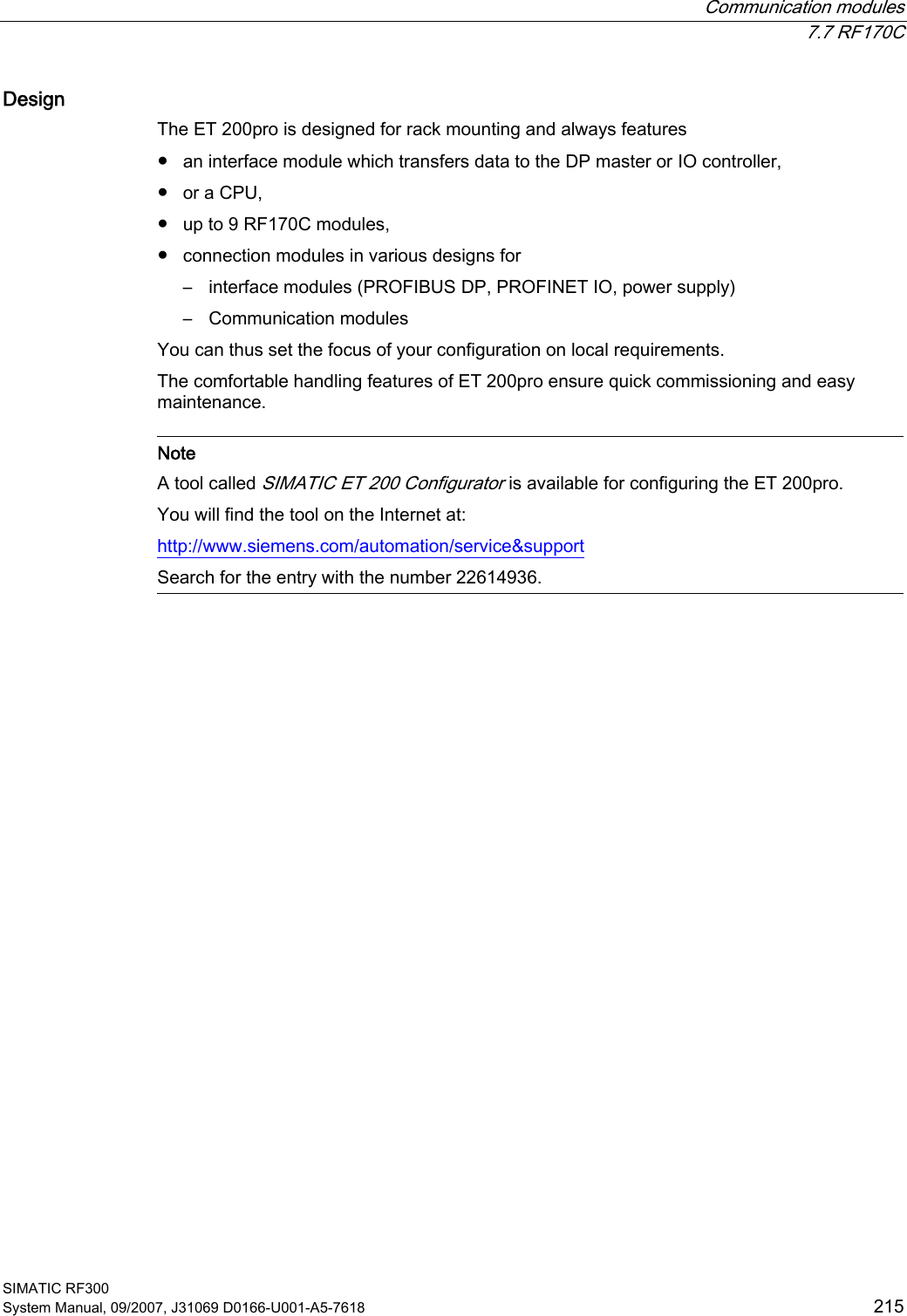
 Transponders  6.7 RF380T SIMATIC RF300 System Manual, 09/2007, J31069 D0166-U001-A5-7618  151 6.7.2.2 Metal-free area Direct mounting of the RF380T on metal is permitted.  Mounting of RF380T on metal  Figure 6-18  Mounting of RF380T on metal Flush-mounting of RF380T in metal: D Figure 6-19  RF380T flush-mounted in metal The standard value for a is ≥ 40 mm. At lower values, the field data change significantly, resulting in a reduction in the range.
Transponders   6.7 RF380T  SIMATIC RF300 152 System Manual, 09/2007, J31069 D0166-U001-A5-7618 6.7.3 Configuring instructions 6.7.3.1 Temperature dependence of the transmission window The guidelines in Section "Planning the RF300 system" apply to configuration of heat-resistant data memories, with the exception of the limit distance and field length at temperatures above 85 °C.  Calculation of transmission window with heat-resistant data memories The factor 0.8 is required for calculating the transmission window, and takes into account production tolerances and temperature influences of to 85 °C. An additional correction factor C must be included in the calculation at temperatures > 85 °C (up to 110 °C):         L  Field length Sg  Limit distance tag - reader VTag  Tag speed C  Correction factor at temperatures > 85 °C  (cf. following picture with correction factor C depending on temperature) tv  Tag dwell time
 Transponders  6.7 RF380T SIMATIC RF300 System Manual, 09/2007, J31069 D0166-U001-A5-7618  153 &>FRUUHFWLRQIDFWRU@7>r&@      5)7 Figure 6-20  Correction factor C depending on temperature The following diagram shows the reduction in the limit distance and field length at increased processing temperatures (internal temperature of tag): ,QWHUQDOWHPSHUDWXUH>r&@         5)7>@ Figure 6-21  Reduction in field length and limit distance The reduction in the field data at higher temperatures is due to the increased current consumption of the electronics.
Transponders   6.7 RF380T  SIMATIC RF300 154 System Manual, 09/2007, J31069 D0166-U001-A5-7618 6.7.3.2 Temperature response in cyclic operation At ambient temperatures (Tu) up to 110 °C, cyclic operation is not necessary, i.e. up to this temperature, the transponder can be in constant operation.    Note Calculation of the temperature curves Calculation of the temperature curves or of a temperature profile can be carried out on request by Siemens AG. Exact knowledge of the internal temperature facilitates configuration for time-critical applications.  Ambient temperatures > 110 °C  NOTICE  Cancellation of warranty The internal temperature of the data memory must not exceed the critical threshold of 110 °C. Each heating phase must be followed by a cooling phase. No warranty claims will otherwise be accepted.  Some limit cycles are listed in the table below: Table 6-7  Limit cycles of data memory temperature Tu (heating up)  Heating up   Tu (cooling down)  Cooling down 220 °C  0.5 h  25 °C  > 2 h 200 °C  1 h  25 °C  > 2 h 190 °C  1 h  25 °C  > 1 h 45 min 180 °C  2 h  25 °C  > 5 h 170 °C  2 h  25 °C  > 4 h The internal temperature of the tag follows an exponential function with which the internal temperature and the operability of the tag can be calculated in advance. This is particularly relevant to temperature-critical applications or those with a complex temperature profile. Ambient temperatures > 220°C  NOTICE  Cancellation of warranty The data memory must not be exposed to ambient temperatures > 220 °C. No warranty claims will otherwise be accepted.  However, the mechanical stability is retained up to 230 °C!
 Transponders  6.7 RF380T SIMATIC RF300 System Manual, 09/2007, J31069 D0166-U001-A5-7618  155 Example of a cyclic sequence Table 6-8  Typical temperature profile of an application in the paint shop Start of tag at initial point  Duration (min)  Ambient temperature (°C) Electrolytic dip  20  30 Electrolytic dip dryer  60  200 Transport  60  25 PVC dryer  25  170 Transport  60  25 Filler dryer  60  160 Transport  60  25 Top coat dryer  60  120 Transport  60  25 Wax dryer  25  100 Transport  150  25  7HPSHUDWXUH.7/EDWK7LPH.7/GU\HU39&GU\HU )LOOHUGU\HU7RSFRDWGU\HU :D[GU\HU>PLQ@>r&@             Figure 6-22  Graphic trend of temperature profile from above table
Transponders   6.7 RF380T  SIMATIC RF300 156 System Manual, 09/2007, J31069 D0166-U001-A5-7618 The simulation results in the following: Following a simulation time of 36.5 hours, a total of 3 cycles were carried out, and an internal temperature of 90 degrees Celsius was reached. 7HPSHUDWXUH7LPH$PELHQWWHPSHUDWXUH0D[LPXPLQWHUQDOWHPSHUDWXUHRIWDJIRUWKLVH[DPSOH,QWHUQDOWHPSHUDWXUHRIWDJ>PLQ@>r&@         Figure 6-23  Complete temperature response due to simulation
 Transponders  6.7 RF380T SIMATIC RF300 System Manual, 09/2007, J31069 D0166-U001-A5-7618  157 6.7.4 Technical specifications Table 6-9  RF380T with 32 KB FRAM Characteristic  Description Memory size  32KB Memory organization  Blocks of 8 bits / 1 byte Serial number  4-byte (fixed code) Application memory  32765 bytes r/w Memory configuration OTP 1)  memory  20 bytes Storage technology  FRAM / EEPROM MTBF (Mean Time Between Failures) in years 1177 Write cycles, at +40°C  Virtually unlimited (>1010) Read cycles  Virtually unlimited (>1010) Read  approx. 0.3 ms/byte Transmission rate Write  approx. 0.3 ms/byte Data retention   > 10 years Write/read distance  dependent on the reader used (see field data) Multitag capability  max. 4 transponders Recommended spacing from metal  can be directly mounted on metal Power supply  Inductive, without battery Degree of protection to EN 60529  IP68 Shock resistant2) to EN 60721-3-7  50 g Vibration2) to EN 60721-3-7  5 g Direction-dependent  No Torsion and bending load  Not permissible continuously Enclosure dimensions  (diam. x H in mm) 114 x 83 Color  Brown Material  PPS Fixing  Support to be ordered separately During operation  -25 °C to +110°C During cyclic operation  -25 °C to +220°C Ambient temperature During transport and storage  -40°C to +110°C Weight  Approx. 900 g 1) OTP: (One Time Programmable) 2) Applies only in connection with original bracket
Transponders   6.7 RF380T  SIMATIC RF300 158 System Manual, 09/2007, J31069 D0166-U001-A5-7618 6.7.5 Ordering data  RF380T/ accessories Order No. • Operating temperature -25 to +200 °C (cyclic) • Dimensions (diam. x H in mm) 114 x 83 • IP 68 degree of protection • 32 KB FRAM (read/write) + 4 byte EEPROM 6GT2800-5DA00 Accessories • Support (short version) • Support (long version) • Covering hood  6GT2090-0QA00 6GT2090-0QA00-0AX3 6GT2090-0QB00  6.7.6 Dimensional drawing SIEMENS6HFXULQJERUGHU$QWHQQDHQG Figure 6-24  Dimension drawing RF380T Dimensions in mm (inches in brackets)
 Transponders   6.8 Memory configuration of the RF300 tags SIMATIC RF300 System Manual, 09/2007, J31069 D0166-U001-A5-7618  159 6.8 Memory configuration of the RF300 tags 5)75)75)75)75)75)7E\WHV8,'UHDGRQO\E\WHV8VHUDUHDUHDGZULWH)5$08VHUDUHDUHDGZULWH((3520273QRWZLWK,46HQVH))))))))))))&)()&))&))))&))))))3K\VLFDOO\LGHQWLFDOPHPRU\:KHQWKH273DUHDLVXVHGWKHFRUUHVSRQGLQJXVHUDUHD))))FDQQRORQJHUEHPRGLILHGUHDGRQO\PD[EORFNVRIE\WHVHDFK5)7.%5)7.%5)7.%5)7.%5)7.%5)7.% Figure 6-25  Memory configuration of the RF300 tags
Transponders   6.8 Memory configuration of the RF300 tags  SIMATIC RF300 160 System Manual, 09/2007, J31069 D0166-U001-A5-7618 Memory areas The memory configuration of an RF300 tag always comprises an EEPROM memory that has 20 bytes for user data (read/write) and a 4 byte unique serial number (UID, read only). For reasons of standardization, the UID is transferred as an 8 byte value through a read command to address FFF0 with a length of 8. The unused 4 high bytes are filled with zeros. A high-speed FRAM memory (read/write) is available as an option. Depending on the tag type, this is 8 KB (0-1FFC) or 32 KB (0-7FFC) in size. The EEPROM memory area (address FF00-FF13) can also be used as a so-called "OTP" memory (One Time Programmable). The 5 block addresses FF80, FF84, FF88, FF8C and FF90 are used for this purpose. A write command to this block address with a valid length (4, 8, 12, 16, 20 depending on the block address) protects the written data from subsequent overwriting.  NOTICE  This operation is not reversible.   OTP area   Note The OTP area cannot be used for the IQ-Sense reader variant. When the OTP area is used, it must be ensured that the blocks are used starting from Block 0 consecutively. Examples: 3 blocks (with write command), Block 0, 1, 2 (FF80, length = 12): valid 2 blocks (consecutive), Block 0 (FF80, length =4), Block 1 (FF84, length = 4): valid 2 blocks (consecutive), Block 0 (FF80, length =4), Block 2 (FF88, length = 4): Invalid 1 Block, Block 4 (FF90, length = 4): Invalid The EEPROM user memory (address FF00-FF13, or FF80-FF90) requires significantly more time for writing (approx. 11 ms/byte) than the high-speed FRAM memory. For time-critical applications with a write function, it is therefore recommended that FRAM tags are used (e.g. RF340T, RF350T, RF360T).
 SIMATIC RF300 System Manual, 09/2007, J31069 D0166-U001-A5-7618  161 Communication modules  77.1 Overview The communication modules (interface modules) are links between the RFID components (reader and transponder) and the higher-level control systems (e.g. SIMATIC S7) or PC or computers.
Communication modules   7.2 8xIQ-Sense  SIMATIC RF300 162 System Manual, 09/2007, J31069 D0166-U001-A5-7618 7.2 8xIQ-Sense 7.2.1 Features Field of application The 8xIQ-Sense module is the link between the RF310R with 8xIQ-Sense interface and SIEMENS S7-300 and functions in the same manner as the communication module (interface module). It can be operated centrally in an S7-300 or decentrally in an ET200M.  Figure 7-1  8xIQ-Sense interface module
 Communication modules   7.2 8xIQ-Sense SIMATIC RF300 System Manual, 09/2007, J31069 D0166-U001-A5-7618  163 7.2.2 Indicators Status displays The 8xIQ-Sense module has the following LEDs:  A green LED, which has no function for RFID devices, and a red SF LED (system fault LED), which indicates the diagnostic state of the module.    LEDs  Labeling  LED status Meaning Green LED per channel 0…7   Has no function here Illuminated Module fault, sensor fault, active teach-in operation, external auxiliary voltage missing  6)60[,46HQVH;)$%;  Red  SF Not illuminated No fault or no active teach-in operation
Communication modules   7.2 8xIQ-Sense  SIMATIC RF300 164 System Manual, 09/2007, J31069 D0166-U001-A5-7618 7.2.3 Configuration Centralized configuration with SIMATIC S7-300 6,0$7,&5)56,0$7,&5)56,0$7,&5)76,0$7,&5)72WKHUPRGXOHVIURPWKH6UDQJHLQFOXGLQJ[,46HQVH$60FKDQQHO5HDGHUZLWK[,46HQVHLQWHUIDFH5HDGHU5HDGHU7UDQVSRQGHU7UDQVSRQGHU[,46HQVH6 Figure 7-2  RF310R reader with 8xIQ-Sense interface
 Communication modules   7.2 8xIQ-Sense SIMATIC RF300 System Manual, 09/2007, J31069 D0166-U001-A5-7618  165 Distributed configuration with ET 200M  6,0$7,&5)56,0$7,&5)56,0$7,&5)76,0$7,&5)72WKHUPRGXOHVIURPWKH6UDQJHLQFOXGLQJ[,46HQVH$60FKDQQHO5HDGHUZLWK[,46HQVHLQWHUIDFH5HDGHU5HDGHU7UDQVSRQGHU7UDQVSRQGHU[,46HQVH(70 Figure 7-3  RF310R reader with 8xIQ-Sense interface Table 7-1  Pin assignment of RF310R with IQ-Sense interface Pin  Pin, device end, 4-pin M12  Assignment 1  IQ-Sense 2  Not assigned 3  IQ-Sense    4  Not assigned
Communication modules   7.2 8xIQ-Sense  SIMATIC RF300 166 System Manual, 09/2007, J31069 D0166-U001-A5-7618 Configuration of connecting cable from 8xIQ-Sense to RF310R PD[P6/*FRQQHFWRU0VRFNHW5HDGHUVLGH,46HQVHVLGHEURZQEOXH Figure 7-4  Cable and pin assignment of RF300 with IQ-Sense
 Communication modules   7.2 8xIQ-Sense SIMATIC RF300 System Manual, 09/2007, J31069 D0166-U001-A5-7618  167 7.2.4 Addressing The address range of the 8xIQ-Sense module is 16 bytes I/O.  This is independent of the choice of channel profiles on the connected device (i.e. the IQ profile IDs in HW Config). Access to memory areas A direct association exists between the number of the channel to which the IQ-Sense device is connected (terminal) and the input and output data area of the module. Based on the address range, the following addresses can be used to access the memory areas: Address = module initial address + (channel no. x 2)
Communication modules   7.2 8xIQ-Sense  SIMATIC RF300 168 System Manual, 09/2007, J31069 D0166-U001-A5-7618 Example Module initial address = 280 I/O address for channel 3: 286 ,46HQVHGHYLFH00ದ00ದ00ದ00ದ00ದ00ದ00ದ00ದ)URQW GRRULQWHULRUFKDQQHO7HUPLQDO&KDQQHODGGUHVVHVLQH[DPSOHIRU,46HQVHGHYLFHV&KDQQHOQRFKDQQHOFKDQQHOFKDQQHOFKDQQHOFKDQQHOFKDQQHOFKDQQHO,4,4,4,4,4,4,4,4/0IRU5),46HQVHGHYLFH,46HQVHGHYLFH,46HQVHGHYLFH,46HQVHGHYLFH,46HQVHGHYLFH,46HQVHGHYLFH,46HQVHGHYLFH5)55)5 Figure 7-5  8xIQ-Sense module: Assignment of terminal pair to memory area    Note A maximum of two read/write devices can be operated!  Each read/write device uses channel numbers 0 to 3 or 4 to 7.
 Communication modules   7.2 8xIQ-Sense SIMATIC RF300 System Manual, 09/2007, J31069 D0166-U001-A5-7618  169 7.2.5 Technical data  Voltages and currents   Rated supply voltage Reverse polarity protection 24 V DC  yes Galvanic isolation • Between the channels • Between channels and backplane bus  no yes Permissible potential difference Between different circuits  75 V DC / 60 V AC Insulation tested at  500 V DC Current input • from the backplane bus • from L+ power supply  120 mA typical 500 mA max. Module power loss  2.5 W typical Module-specific data  Number of channels Channels for RFID systems 8 2 Cable length, unshielded  50 m max. Dimensions and weight  Dimensions w x h x d (mm)  40 x 125 x 120 Weight   Approx. 235 g  7.2.6 Ordering data Table 7-2  Ordering data for 8xIQ-Sense and accessories Product description  Order No. SIMATIC S7-300  IQ-Sense SM338 for S7-300 and ET200M for the connection of up to 8xIQ-Sense sensors Optical sensors, ultrasonic sensors and RF identification systems can be connected. 6ES7 3387XF000AB0 Accessories M12 cable plug, 4-pole, with 5 m black PUR cable, 4 x 0.34 mm2 3RX8000-0CB42-1AF0 M12 cable plug, 4-pole, with 10 m black PUR cable, 4 x 0.34 mm2 3RX8000-0CB42-1AL0
Communication modules   7.3 ASM 452  SIMATIC RF300 170 System Manual, 09/2007, J31069 D0166-U001-A5-7618 7.3 ASM 452 7.3.1 Features Area of application The ASM 452 interface module is a MOBY module for operating MOBY and RF300 components with RS422 over PROFIBUS DP-V1 on ●  Any computers and PCs ●  Any PLCs When operating the interface module on a SIMATIC S7, function blocks are made available to the user.  Figure 7-6  Interface module ASM 452 The ASM 452 is the result of consistent development of the familiar ASM 450/451 interface modules. Optimal data throughput can be achieved even in large-scale PROFIBUS configurations thanks to the use of acyclic data traffic on PROFIBUS DP V1. The minimum cyclic data load of the ASM 452 on the PROFIBUS provides the user with the guarantee that other PROFIBUS nodes (e.g. DI/DO) can still be processed at great speed. The ASM 452 is an interface module for communication between PROFIBUS and the RF310R with RS422 interface. Through the ASM 452, the data on the RF300 transponder can be physically addressed ("Normal" addressing). In SIMATIC S7, FC 45 is available for this purpose.
 Communication modules  7.3 ASM 452 SIMATIC RF300 System Manual, 09/2007, J31069 D0166-U001-A5-7618  171 7.3.2 Pin assignment and display elements Pin assignments The figure below illustrates the pin assignments of ASM 452. 352),%86'36RFNHW;DQG;3LQDVVLJQPHQW 6LJQDO % UHG 3( 3( 6LJQDO $ JUHHQ / 06XSSO\YROWDJH/('VIRU5)DQG$605[' 5HDGHU DFWLYH ZLWK35((55 7UDQVSRQGHUSUHVHQWRUHUURU GLVSOD\35((55 IRUUHDGHU7KHWUDQVSRQGHUSUHVHQWGLVSOD\DOZD\VWDNHVSULRULW\7KHHUURULVRQO\LQGLFDWHGZKHQDWUDQVSRQGHULVQRWSUHVHQW7UDQVSRQGHUSUHVHQW7KH/('LVSHUPDQHQWO\21,IPRUHWKDQRQHWUDQVSRQGHULVLQWKHILHOGWKH  QXPEHURIWUDQVSRQGHUVLVLQGLFDWHGE\VKRUWLQWHUUXSWLRQV$IDXOWLVQRWRXWSXW(UURUGLVSOD\7KH/('LVSHUPDQHQWO\2))7KHODVWHUURUQXPEHULVLQGLFDWHGE\EULHIOLJKWSXOVHV5HDGHU 5HDGHULVVHOHFWHG5HDGHU 5HDGHULVVHOHFWHG2QO\UHDGHUFDQEHVHOHFWHG/('VIRU352),%86'36) 6\VWHP )DXOW%) %XV )DXOW21 /LJKWV XS ZKHQ WKHUH LV$60LVJHQHUDWHGE\WKH9VXSSO\YROWDJH9'& /LJKWVXSZKHQWKH9VXSSO\YROWDJHLVFRQQHFWHGWRWKH$601RWFRQQHFWHG3LQDVVLJQPHQWUHDGHU6RFNHW1RWDYDLODEOHIRU5);;;;$60; ;; ;;;;'&95['35((556/*5['6/*35((556)%)21 3( / 0 3( / 0; 5[' 7[' 7[' 5[' 3(; ;  9 9 '$ '(  9 9 '$ '( 3( 3( Figure 7-7  Pin assignment and LEDs of ASM 452
Communication modules   7.3 ASM 452  SIMATIC RF300 172 System Manual, 09/2007, J31069 D0166-U001-A5-7618 7.3.3 Configuration Configuration Hardware description The ASM 452 has the same housing as the distributed I/O system ET 200X. General information on ASM 452 (e.g. assembly, operation and wiring; general technical data) is available in the ET200X manual (Order No. 6ES7 198-8FA00-8AA0). Descriptions of accessories and network components can also be found in this manual. Configuration 5)[[75)[[5352),%86FDEOHV9IRU$60WRRWKHU352),%86QRGHV352),%86'3PDVWHUPRGXOHHJ6&386,0$7,&5)56,0$7,&5)7 Figure 7-8  ASM 452 configurator
 Communication modules  7.3 ASM 452 SIMATIC RF300 System Manual, 09/2007, J31069 D0166-U001-A5-7618  173 PROFIBUS configuration The ASM 452 is integrated into the hardware configuration by means of a GSD file. The ASM can then be configured using the HW Config of SIMATIC Manager or another PROFIBUS tool. A GSD file is provided for ASM 452 on the CD "RFID Systems Software & Documentation". Operating mode of the ASM 452 The approved operating modes of ASM 452 are described in the GSD file. It is set using the hardware configuration tool (e.g. STEP 7 HW Config). Reader connection system A reader always occupies two M12 connector sockets on the ASM 452. A pre-assembled cable therefore ensures easy connection of the reader (see figure below). The connecting cable is available in lengths of 2 m (standard) and 5 m. Extensions are possible up to 1000 m using connecting cables 6GT2891-… .  JUD\JUHHQZKLWHEURZQ\HOORZSLQNVKLHOG7ZRSLQ0FLUFXODUFRQQHFWRUV$60VLGH 5HDGHUVLGH0SLQ ;;;;;;; ; ;; Figure 7-9  Connecting cable (2 m) ASM 452/473 ↔ RF3xxR reader with RS422 (6GT2891-1CH20)
Communication modules   7.3 ASM 452  SIMATIC RF300 174 System Manual, 09/2007, J31069 D0166-U001-A5-7618 Cable installation  Signal  M12 (reader side)  Cable  X1 / Data  X2 24 V DC  1  Pink  -  1 TX -  2  Yellow  4  - GND  3  Gray  -  3 TX +  4  Green  1  - RX +  5  white  2  - RX -  6  brown  3  - -      -  - Shield  8 + terminal piece  Shielding  5  5 Cable assignment ASM 452/473 ↔ RF3xxR reader with RS422 (6GT2891-1CH20) A reader cable connector with screw-type terminals is provided for users who want to individually pre-assemble their own cables (see figure below). Cables and reader cable connectors can be ordered from the MOBY catalog.  66VFUHZVIRURSHQLQJWKHFRQQHFWRU&RQQHFWRU0WR$60'HJUHHRISURWHFWLRQ,33*FDEOHJODQGPD[FDEOHGLDPHWHU PPRQO\VFUHZGRZQDIWHUDVVHPEOLQJWKHFRQQHFWRU$60FDEOH*7 &RQQHFWRUFRYHUUHPRYHG Figure 7-10  Cable connector ASM 452/473 ↔ RF3xx reader with RS422 (6GT2090-0BC00)  Pin assignment for ASM 452/473 cable connector  Connector pin  Connection to pin of the reader  Wire color 1  4 2  5 3  6 4  2 5  3 6  1  - S  8 + terminal piece Note data sheet provided by the manufacturer Pin 7 must not be connected.
 Communication modules  7.3 ASM 452 SIMATIC RF300 System Manual, 09/2007, J31069 D0166-U001-A5-7618  175 PROFIBUS cable with 24 V supply The ASM 452 can also be operated with the "green" PROFIBUS cable. It is important to ensure that a 24 V cable is connected from X12 to X13. The 24 V cable can be connected to pins 5 and 6 in plug X12. ; ;;; ;; Figure 7-11  PROFIBUS cable with 24 V supply PROFIBUS address and terminating resistor You must remove the connector plate from the ASM before you set the  PROFIBUS address or connect the terminating resistor. The connector plate covers the DIL switch. The position of the DIL switch in ASM is shown in the figure below with one setting example for each case. 212IIRQ  ([DPSOH352),%86DGGUHVVRQGHOLYHU\([DPSOH7HUPLQDWLQJUHVLVWRU2II $VGHOLYHUHGVWDWH6WDQGDUGPRGHXVH*6'ILOH6,(0%   Figure 7-12  Setting the PROFIBUS address/connecting the terminating resistor   Note • The PROFIBUS address in ASM 452 must always match the PROFIBUS address defined in the configuring software for this ASM. • To ensure that the terminating resistor functions correctly, you must always switch both DIL switches of the terminating resistor to "on" or "off".
Communication modules   7.3 ASM 452  SIMATIC RF300 176 System Manual, 09/2007, J31069 D0166-U001-A5-7618 7.3.4 Technical data Table 7-3  Technical data for ASM 452   ASM 452 with FC 45 Serial interface to the user  PROFIBUS DP-V1 Procedure after connection  EN 50170 Vol. 2 PROFIBUS  PG 11 cable gland PROFIBUS and power supply connectors are not included in the scope of delivery Transmission rate  9600 baud to 12 Mbaud (automatic detection) Max. block length  2 words cyclic/240 bytes acyclic Serial interface to the RF3xxR   Connector  2 x M12 coupler plug Max. cable length  2 m = Standard length, 5 m, 10 m, 20 m and 50 m, (up to 1000 m on request) Readers that can be connected  1x RF3xxR with RS422 interface Software functions   Programming  Depending on the PROFIBUS DP master Function blocks for SIMATIC S7  FC 45 Transponder addressing  Direct access via addresses Commands  Initialize transponder, read data from transponder, write data to transponder Multi-tag capability  No S7 data structures via UDTs  Yes Power supply   Rated value  24 V DC Permissible range  20 V to 30 V DC Current consumption  Max. 180 mA; typ. 130 mA (without reader) Digital inputs  none Digital outputs  None Ambient temperature   During operation  0 °C to +55 °C Storage and transport  -40 °C to +70 °C Dimensions (W x H x D) in mm  134 x 110 x 55 (without bus connector) Fixing  4 M5 screws; for mounting on any plate or wall Weight, approx.  0,5 kg Degree of protection  IP67 MTBF (at 40 °C)  30 • 104 hours = 34 years
 Communication modules  7.3 ASM 452 SIMATIC RF300 System Manual, 09/2007, J31069 D0166-U001-A5-7618  177 7.3.5 PROFIBUS Diagnosis The following table lists possible error indications with their meanings and provides remedies. Table 7-4  LED indication for PROFIBUS diagnosis "BF" LED  "SF"LED  Cause of error  Error correction • ASM 452 is in start-up mode.  - • The connection to the DP master has failed. • ASM 452 not detecting a baud rate. • Check the PROFIBUS DP connection. • Check the DP master. ON  * • Bus interrupt • DP Master not functioning • Check all cables on your PROFIBUS DP network. • Check whether the connector plugs for PROFIBUS DP are securely plugged into the ASM 452. flashes  on  • The configuration data sent to the ASM 452 by the DP master do not match the configuration of the ASM 452. • Check the configuration of the ASM 452 (input/output, PROFIBUS address). • Correct GSD file being used?–  SIEM80B6.GSD for ASM 452 Flashes  Off  • ASM 452 has detected the baud rate, but is not being addressed by the DP Master. • ASM 452 has not been configured. • Check the PROFIBUS address set on the ASM 452 or in the configuration software. • Check the configuration of the ASM 452 (station type). on  Flashes  • There is a hardware defect in the ASM 452. • Replace the ASM 452.
Communication modules   7.3 ASM 452  SIMATIC RF300 178 System Manual, 09/2007, J31069 D0166-U001-A5-7618 7.3.6 Dimension drawing The following figure shows the dimensional drawing of an ASM 452 with bus connectors. You must add the length of the PG cable gland and the radius of the cable used to the measured overall width and depth.   Figure 7-13  Dimensional drawing of ASM 452 Example of stripped lengths The following diagram shows an example of stripped lengths. The lengths apply to all cables which can be connected to the connector plugs. You must twist any shield braid present, plug into a core end sleeve and cut off any excess. 7ZLVWHGDQGWUXQFDWHGVKLHOGEUDLGLQJ Figure 7-14  Length of stripped insulation for PROFIBUS cables
 Communication modules  7.3 ASM 452 SIMATIC RF300 System Manual, 09/2007, J31069 D0166-U001-A5-7618  179 7.3.7 Ordering data Table 7-5  Ordering data for ASM 452 and accessories Product description  Order No. ASM 452 interface module for PROFIBUS DP-V1, 1x RF3xxR with RS422 interface, without connector for 24 V DC and PROFIBUS 6GT2002-0EB20 Accessories: Connector for PROFIBUS DP and 24 V supply  6ES7194-1AA00-0XA0 Connecting cable RF3xxR ↔ ASM 452  Plug-in cable, pre-assembled, length: 2 m (standard length)  6GT2891-1CH20  Plug-in cable, pre-assembled, length: 5 m  6GT2891-1CH50 Opt. Cable connector without read/write device cable  (for cable lengths > 20 m) ASM 452 ↔ reader 6GT2090-0BC00 M12 blanking cap for unused RF310R connection (1 pack = 10 pieces) 3RX9802-0AA00 CD "RFID Systems Software & Documentation" with FC 45, GSD file 6GT2080-2AA10 Replacement part: Connector plate; T functionality for PROFIBUS connection  6ES7194-1FC00-0XA0 FC 45 Reference Manual German English French  Available in electronic form on the CD "RFID Systems Software & Documentation" The ASM 456 plug-in cables 6GT2891-0Fxxx can be used as extension cables.
Communication modules   7.4 ASM 456  SIMATIC RF300 180 System Manual, 09/2007, J31069 D0166-U001-A5-7618 7.4 ASM 456 7.4.1 Description Field of application The ASM 456 interface modules are slave modules for operating RF300 components via the PROFIBUS DP/DP-V1 on any control systems.  Figure 7-15  Interface module ASM 456 with ECOFAST connection block or M12, 7/8" When operating the interface module on a SIMATIC S7, convenient function blocks are made available to the user.
 Communication modules  7.4 ASM 456 SIMATIC RF300 System Manual, 09/2007, J31069 D0166-U001-A5-7618  181 Features The ASM 456 replaces the ASM 452 in terms of functionality and provides a simplified connection system. You can continue to use the user software from ASM 452. Optimum data throughput can be achieved through acyclic data traffic on the PROFIBUS DP V1 even when using large PROFIBUS configurations. The minimum cyclic data load of the ASM 456 on the PROFIBUS provides the user with the guarantee that other PROFIBUS consumers (e.g. DI/DO) can still be processed at great speed. Up to 2 readers can be operated in parallel on the ASM 456. The user can start a command in parallel on 2 readers (via the corresponding FB/FC). The transponder data are accessed by means of physical addressing of the reader. In SIMATIC S7, the FC 45 is available for this purpose. The FC 45 provides the S7 user with a simple-to-use interface with powerful commands (processing one complete transponder with one command; command linking; S7 data structures via UDTs). Other features ●  Degree of protection IP67 ●  System integration with ECOFAST or M12, 7/8" concept ●  T functionality, that is, a component can be replaced without adversely affecting other modules with regard to bus communication and voltage supply ●  Standardized PROFIBUS user interface for identification systems with PIB (Proxy Ident Function Block; with later firmware version). ●  Firmware update ●  PROFIBUS interface module up to 12 Mbaud with automatic baud rate detection ●  Parameterizable device-related diagnostics data with text display ●  Support for I&M functionality (a mechanism for reading out information via the module and saving system information such as function, installation date, installation location, and comments.)
Communication modules   7.4 ASM 456  SIMATIC RF300 182 System Manual, 09/2007, J31069 D0166-U001-A5-7618 Design The ASM 456 has the same housing as the distributed I/O system ET 200eco. The ASM has a connection block for connecting up to the PROFIBUS DP which is available as an option and the ECOFAST version or M12, 7/8". The following figure shows the basic design of the ASM 456.  &RQQHFWRUVRFNHWIRUVWUHDGHU6WDWXV/('VIRURSHUDWLRQRIWKHQGUHDGHU6WDWXV/('VIRULQWHUIDFHPRGXOH5HDGHU6WDWXV/('VIRURSHUDWLRQRIWKHVWUHDGHU&RQQHFWRUVRFNHWIRUQGUHDGHU6SDFHIRUFRQQHFWLRQEORFN3URWHFWLYHHDUWK;;*7('02%<$60 Figure 7-16  Basic design of the ASM 456
 Communication modules  7.4 ASM 456 SIMATIC RF300 System Manual, 09/2007, J31069 D0166-U001-A5-7618  183 Configuration The following figure shows how the ASM 456 is integrated in an automation system. 6,0$7,&5)76,0$7,&5)76,0$7,&5)56,0$7,&5)5;P6WDQGDUGFDEOHOHQJWK352),%86FDEOHV9IRU$60DQGUHDGHUWRRWKHU352),%86QRGHV352),%86'3PDVWHUPRGXOHHJ6&385HDGHU 5HDGHU7UDQVSRQGHU;$60b Figure 7-17  ASM 456 configurator  The ASM 456 is integrated into the hardware configuration by means of a GSD file. The ASM can then be configured using HW Config of SIMATIC Manager or another PROFIBUS tool (e.g. operating mode). The GSD file can be found on the "RFID Systems Software & Documentation" CD or on the Internet.
Communication modules   7.4 ASM 456  SIMATIC RF300 184 System Manual, 09/2007, J31069 D0166-U001-A5-7618 7.4.2 Setting the PROFIBUS address Features The PROFIBUS address defines the address at which the ASM 456 distributed I/O system is found on the PROFIBUS DP. Requirements ●  The PROFIBUS DP address for the ASM 456 is set on the connection block. ●  Each address can be assigned only once on the PROFIBUS DP. ●  The PROFIBUS address set must match the PROFIBUS address defined in the configuring software (for the ASM 456). ●  Changes to the PROFIBUS DP address only take effect once the mains have been switched ON on the ASM 456. Tools required for M12, 7/8” connection block ●  Socket wrench 14 mm ●  Screwdriver with 2.5 mm blade
 Communication modules  7.4 ASM 456 SIMATIC RF300 System Manual, 09/2007, J31069 D0166-U001-A5-7618  185 Setting PROFIBUS DP addresses on connection block M12, 7/8” Valid PROFIBUS DP addresses are 1 to 99.  1. Remove the two seal caps from the rotary switches (if necessary, use a 14 mm socket wrench). 2. Set the required PROFIBUS address on the rotary switches using a screwdriver. –  Lower rotary switch: 1st position –  Upper rotary switch: 10th position 3. Screw the two seal caps back onto the rotary switches  (torque: 0.5 Nm to 0.8 Nm.) [[[[5RWDU\VZLWFKIRU352),%86'3DGGUHVV3RVLWLRQ3RVLWLRQ352),%86DGGUHVV([DPSOH Figure 7-18  Setting PROFIBUS addresses on connection block M12, 7/8”
Communication modules   7.4 ASM 456  SIMATIC RF300 186 System Manual, 09/2007, J31069 D0166-U001-A5-7618 Setting PROFIBUS DP addresses on connection block ECOFAST Valid PROFIBUS DP addresses are 1 to 99.  1. Loosen the screw connection of the configuration plug with the ECOFAST connection block and remove the plug.  Figure 7-19  Loosening the configuration plug's screw connection 2. Loosen the screw connection for the cover cap on the configuration plug and remove the latter. 3. Set the PROFIBUS address using the DIL switches. ([DPSOH352),%86DGGUHVV  21 21  Figure 7-20  Setting PROFIBUS address on configuration plug 4. Screw the cover cap back down, plug the configuration plug onto the connection block and screw the configuration plug to the connection block.
 Communication modules  7.4 ASM 456 SIMATIC RF300 System Manual, 09/2007, J31069 D0166-U001-A5-7618  187 7.4.3 Wiring up ASM 456 Wiring ECOFAST connector plugs The table below contains the connector assignment for the ECOFAST connector plugs Table 7-6  Connection assignment for ECOFAST connector plugs Pin  Assignment  View of ECOFAST connector plug  (wiring end for supply and loop-through connection) A  PROFIBUS DP signal A B  PROFIBUS DP signal B 1  Electronics / encoder supply (1L+) (voltage supply for ASM 456 and reader) 2  Ground for electronic / encoder supply (1M) 3  Ground for load voltage supply (2M) 4  Load voltage supply (2L+) (unused on ASM 456)  $%//6LJQDO$6LJQDO%(&2)$67K\EULGFDEOH  *) You will find the assembly instructions in the packaging of the Han Brid Cu cable connector and/or Han Brid Cu cable socket.
Communication modules   7.4 ASM 456  SIMATIC RF300 188 System Manual, 09/2007, J31069 D0166-U001-A5-7618 Wiring M12, 7/8" connector The tables below contain the connector assignment for the M12, 7/8" connector: Table 7-7  Connection assignment for M12 connector (PROFIBUS DP) Pin  Assignment  View of M12 connector  (wiring side) 1  Supply positive (P5V2) * 2  Data line A (RxD / TxD-N) 3  Data reference potential (M5V2) * 4  Data line B (RxD / TxD-P) 5  Shield Thread  Shield  6LJQDO$JUHHQ6LJQDO%UHG6KLHOG6XSSO\'36LJQDO$JUHHQ6LJQDO%UHG6KLHOG%XVFDEOHFRUHVKLHOGHG/RRSWKURXJKFRQQHFWLRQ'3 *) Can only be used for the M12 terminating resistor. Looping the voltage through to the next connector via a 5-core cable is not permitted.
 Communication modules  7.4 ASM 456 SIMATIC RF300 System Manual, 09/2007, J31069 D0166-U001-A5-7618  189 Table 7-8  Terminal assignment of the 7/8" connector (supply voltages) Pin  Assignment  View of 7/8" connector  (wiring side) 1  Ground for load voltage supply (2M) 2  Electronics/sensor supply ground (1M) 3  PE 4  Electronics / encoder supply (1L+) (voltage supply for ASM 456 and reader) 5  Load voltage supply (2L+) (unused on ASM 456)  ////6XSSO\;FRUHFDEOH/RRSWKURXJKFRQQHFWLRQ;    Note When connecting up the supply voltage, we recommend that the cable 6XV1 822-5B... (5 x 1.5 mm2 pre-assembled with 7/8" connectors) is used. If you want to assemble the cable yourself, then the conductor cross-section should be 1.5 mm2.
Communication modules   7.4 ASM 456  SIMATIC RF300 190 System Manual, 09/2007, J31069 D0166-U001-A5-7618 Connecting the ASM 456 up to protective earth 1. Isolate the grounding cable and secure the cable lug. 2. Screw the cable lug down to the ASM 456 (M5 retaining bolt). The torque is 3 Nm.  Figure 7-21  Connecting the ASM 456 up to protective earth Connecting RF310 reader to ASM 456 O Figure 7-22  Connecting cable, l = 2 m, 5 m, 10 m, 20 m, 50m ( 6GT2891-0Fxxx)
 Communication modules  7.4 ASM 456 SIMATIC RF300 System Manual, 09/2007, J31069 D0166-U001-A5-7618  191 Maximum cable length The ASM 456 can be operated with any SLG configuration with a maximum cable length of 50 m. Longer connecting cables of up to 1000 m are possible in some instances. The current consumption of the connected reader must however be taken into account. A number of cables must not be joined together to form a long cable due to the additional contact resistances. Cable assembly by the customer A reader connection plug with screw-type terminals is available for users who want to make their own cables.  Cables and reader cable connectors can be ordered according to the MOBY catalog. For self-assembled cables, you will need cable to the following specifications: 7 x 0.25 mm2 LiYC11Y 7 x 0.25 M12 connectors can be purchased from appropriate electrical retailers (e.g. Binder in Germany). The pin assignment is listed in the following table. Table 7-9  Pin assignment M12 connector (male)  Pin  Signal  Wire color 1  +24 V 2  −RxD 3  0 V 4  RxD 5  TxD 6  −TxD 7  Free   8  PE / shield Note data sheet provided by cable manufacturer
Communication modules   7.4 ASM 456  SIMATIC RF300 192 System Manual, 09/2007, J31069 D0166-U001-A5-7618 7.4.4 Diagnosis using LEDs The following figure shows details of the LEDs of the ASM 456. 352),%866) %) 21 '&9;;*7('02%<$60$&7B 35(B5['B (55B$&7B 35(B5HDGHU5HDGHU5['B (55B Figure 7-23  LEDs of the ASM 456 Table 7-10  Status LEDs for ASM 456 LEDs  Meaning* ON  Lights up when there is logic voltage at the ASM (is generated by the 24 V supply voltage.)  24 V DC  Lights up when the 24 V supply voltage is connected to the ASM. ACT_1, ACT_2  The corresponding reader is active in processing a user command. ERR_1, ERR_2 *  A flashing pattern indicates the last error to occur. PRE_1, PRE_2 **  Indicates the presence of a transponder. RxD_1, RxD_2  Indicates live communication with the reader. May also indicate malfunctions on the transponder. *) The meaning of the individual flash patterns and the associated fault descriptions can be found in the relevant FB and FC documentation. **) In multitag mode, this LED uses a flash interval to indicate the number of data media currently within the range of influence of the reader.
 Communication modules  7.4 ASM 456 SIMATIC RF300 System Manual, 09/2007, J31069 D0166-U001-A5-7618  193 Table 7-11  LED display for PROFIBUS diagnosis BF  SF  Cause of error  Error handling • ASM is in start-up mode.  – • Connection to DP Master failed. • ASM not detecting a baud rate • Check the PROFIBUS DP connection. • Check the DP Master On  – • Bus interrupt • DP Master not functioning • Check all cables on your PROFIBUS DP network. • Check whether the connector plugs for the PROFIBUS DP are securely plugged into the ASM. flashes  On  • The project data sent to the ASM by the DP Master do not match the configuration of the ASM. • Check the project for the ASM (input/output, PROFIBUS address). • Correct GSD file being used? flashes  –  • ASM has detected the baud rate, but is not activated by the DP Master. • ASM has not been assigned project plans. • Check the PROFIBUS address set in ASM and/or in the project software. • Check the project for the ASM (station type). On  flashes  • There is a hardware defect in the ASM. • Replace the ASM. Off  On  • Diagnosis available  • Evaluate the diagnostic information. On  Off  • The set PROFIBUS address is incorrect or greater than 99. • Set the address in the range 1 to 99 and carry out new ramp-up. – = Status not relevant  Other ASM operating modes are indicated by the PRE, ERR, ACT, SF and ON LEDs:   ON  SF  PRE_1  ERR_1  ACT_1  PRE_2  ERR_2  ACT_2  Description On  Off  Off  Off  On  Off  Off  Off  Ramp-up active Off  On  Off  On  Off  Off  Off  Off  Checksum error at ramp-up Off  On  Off  Off   Off  Off  On  Off  Firmware invalid On  On  On  On  On  On  On  On  LED test for approximately 4 seconds; otherwise firmware fault Off  On  Off  On  On  Off  On  On  Checksum error at ramp-up Off  On  On  On  On  Off  On  On  Checksum error of the firmware Off  On  On  On  On  On  On  On  External RAM defective Off  On  On  Off  On  On  On  On  DPC-RAM defective Off  On  Off  On  On  On  On  On  ID error firmware On  –  Off  1 x flash every 3 s Off  Off  1 x flash every 3 sOff  ASM successfully ramped up, waiting for reset command On  –  –  Flashing  Rapid flashing –  Flashing  Rapid flashing Firmware update; alternate flashing of the error LEDs at approximately 1 Hz – = not relevant
Communication modules   7.4 ASM 456  SIMATIC RF300 194 System Manual, 09/2007, J31069 D0166-U001-A5-7618 7.4.5 Technical data Table 7-12  Technical data for ASM 456 Serial interface to the user  PROFIBUS DP-V1 Procedure after connection  EN 50170 Vol. 2 PROFIBUS M12 and 7/8" technology / ECOFAST Transmission rate  9600 baud to 12 Mbaud (automatic detection) Max. block length  2 words cyclic/240 bytes acyclic Serial interface to the reader   • Connector  2 x M12 coupler plug • Max. cable length  1000m, reader dependent; 2 m = Standard length; (up to 1000 m on request) Extension cable = 2 m, 5 m, 10 m, 20 m and 50 m• Readers that can be connected  2 x reader Software functions   Programming  Depending on the PROFIBUS DP master Function blocks:   • SIMATIC S5  – • SIMATIC S7  FC 45 (normal addressing without multitag) Transponder addressing  Direct access via addresses Commands  Initialize transponder, read data from transponder, write data to transponder, etc. Supply voltage: 2  • Rated value  24 V DC • Permissible range  20 V to 30 V DC Current consumption 1  Max. 800 mA; typ. 80 mA (without reader) Galvanic isolation  Yes Ambient temperature    • During operation  0 °C to +55 °C • Storage and transport  –40 to +70 °C Dimensions (W x H x D) in mm   • ASM 456 only  60 x 210 x 30 • ASM 456 with ECOFAST connection block  60 x 210 x 60 Weight, approx.  210 g Degree of protection  IP67 MTBF (at 40 °C)  122 years 1) The power supply must deliver the required current of up to 800 mA for brief power failures ≤ 20 ms. 2) All supply voltages and signal voltages must be protective low level voltage (SELV/PELV acc. to EN 60950) 24V DC supply: Safety (electrical) isolation of low voltage (SELV / PELV acc. to EN 60950)
 Communication modules  7.4 ASM 456 SIMATIC RF300 System Manual, 09/2007, J31069 D0166-U001-A5-7618  195 7.4.6 Dimension drawing The following figure shows the dimensional drawing of an ASM 456 with bus connection block.  [[[[02%<$6002%<$60[[:LWKFRQQHFWLRQEORFN0 :LWKFRQQHFWLRQEORFN(&2)$67   Figure 7-24  Dimensional drawing of ASM 456 (in mm)
Communication modules   7.4 ASM 456  SIMATIC RF300 196 System Manual, 09/2007, J31069 D0166-U001-A5-7618 7.4.7 Ordering data Table 7-13  Ordering data for ASM 456 and accessories Product description  Order number ASM 456 interface module  for PROFIBUS DP V1 max. 2 readers can be connected 6GT2002-0ED00 Accessories for ECOFAST connection: Connection block ECOFAST  6ES7194-3AA00-0AA0 PROFIBUS ECOFAST hybrid plug 180   with pin insert (5 per pack)  6GK1905-0CA00 with socket insert (5 per pack)  6GK1905-0CB00 PROFIBUS ECOFAST termination plug with terminating resistor  6GK1905-0DA10 ECOFAST hybrid cable, pre-assembled  6XV1830-7B... 1) ECOFAST hybrid cable, not pre-assembled, sold by the meter  6XV1830-7AH10 Accessories for M12 7/8" connection: Connection block M12  6ES7194-3AA00-0BA0 M12 terminal resistor for PROFIBUS (5 per pack)  6GK1905-0EC00 PROFIBUS cable with M12 connectors, pre-assembled   6XV1830-3D... 1) Cable for supply voltage with pre-assembled 7/8" connectors  6XV1822-5B... 1) PROFIBUS FC standard non-pre-assembled cable;  max. length 1000 m 6XV1830-0EH10  PROFIBUS M12 connector plug (5 per pack) with pin insert  6GK1905-0EA00 with socket insert  6GK1905-0EB00 Connector plug 7/8" for voltage (5 per pack) with pin insert  6GK1905-0FA00 with socket insert  6GK1905-0FB00 Cable accessories:  Plug-in cable, pre-assembled, length 2 m (standard length)  6GT2891-0FH20 Plug-in cable, pre-assembled, length 5 m  6GT2891-0FH50 Plug-in cable, pre-assembled, length 10 m  6GT2891-0FN10 Plug-in cable, pre-assembled, length 20 m  6GT2891-0FN20 Plug-in cable, pre-assembled, length 50 m  6GT2891-0FN50 Angled extension for direct connection of reader to ASM 456 or for extending any plug-in cables 6GT2891-0JH20 CD "RFID Systems Software & Documentation" with FC 45, GSD file 6GT2080-2AA10 Other accessories for ASM 456 (network components)  ET 200eco manual  6ES7198-8GA00-8AA0 Description of FC 45 (for ASM 456) German English French  Available in electronic form on the CD "RFID Systems Software & Documentation" 1) These cables are available in different lengths. See Catalog IK PI for more details
 Communication modules  7.5 ASM 473 SIMATIC RF300 System Manual, 09/2007, J31069 D0166-U001-A5-7618  197 7.5 ASM 473 7.5.1 Features Field of application The ASM 473 interface module is an RF300 module for SIMATIC S7. It can be plugged into the ET 200X distributed I/O station and DESINA. ET 200X is operated by the user over PROFIBUS DP V1. An S7-300 or S7-400 with integrated PROFIBUS connection can be used as the controller.  ASM 473 supplements the SIMATIC S7 interface module ASM 475. The IP67 degree of protection means that it can be installed and operated in the process without the need for an additional protective housing. To operate the ASM 473, an ET 200X basic module BM 141/142 with the order number 6ES7141-1BF11-0XB0 or 6ES7142-1BD21-0XB0 or a BM 143 is required. The transponder data are accessed by means of physical addressing of the transponder. For operation in a SIMATIC S7, the function FC 45 is available. The hardware of the ASM 473 is configured with an object manager (OM) that is integrated in the SIMATIC Manager.  Figure 7-25  Interface module ASM 473 Other features: ●  Up to 7 ASM 473 interface modules can be operated simultaneously in an ET 200X station. ●  Any other I/O modules from the ET 200X spectrum can be operated with the ASM 473.
Communication modules   7.5 ASM 473  SIMATIC RF300 198 System Manual, 09/2007, J31069 D0166-U001-A5-7618 7.5.2 Pin assignment and display elements Pin assignments The figure below illustrates the pin assignment for the read/write device and the display elements.    2))+]+]2))21+]+]+]2));;21SHUP2))21 5[' 7[' 7[' 5[' 3( 9 QF 9 QF 3((5535([IODVKHYHU\V6RFNHW 3LQDVVLJQPHQWUHDGHU/('VIRU352),%86'3*HQHUDOLQGLFDWRUV6)%)219'&DUHORFDWHGRQWKHEDVLFPRGXOHRIWKH(7;/('VIRU02%<5[' 5HDGHUDFWLYHZLWKFRPPDQG35( ,QGLFDWHVWKHSUHVHQFHRIDWUDQVSRQGHU(55 (UURULQGLFDWHGE\IODVKLQJVHTXHQFH7KHIROORZLQJ$60VWDWHVDUHDOVRLQGLFDWHGZLWKWKH/('V35(DQG(55'HVFULSWLRQ&DXVHV5HPHG\+DUGZDUHLVGHIHFWLYH5$0IODVK&KDUJHULVGHIHFWLYHFDQRQO\EHUHSDLUHGLQWKHIDFWRU\)LUPZDUHORDGLQJLVDFWLYHRUQRILUPZDUHGHWHFWHGൺ/RDGILUPZDUHൺ$60PXVWQRWEHVZLWFKHGRIIXQWLOORDGHG)LUPZDUHORDGLQJWHUPLQDWHGZLWKHUURUVൺ5HVWDUWUHTXLUHGൺ/RDGILUPZDUHDJDLQൺ&KHFNXSGDWHILOHV2SHUDWLQJV\VWHPHUURUൺ6ZLWFK$60RU(7;EDVHVWDWLRQ2))21$60KDVERRWHGDQGLVZDLWLQJIRUD5(6(7LQLWBUXQIURPWKHXVHU Figure 7-26  Interfaces and indicators of the ASM 473 for RF300
 Communication modules  7.5 ASM 473 SIMATIC RF300 System Manual, 09/2007, J31069 D0166-U001-A5-7618  199 7.5.3 Configuration 5)[[75)[[59VXSSO\IRU5)[[59VXSSO\IRU(7;(OHFWURQLFVWRRWKHU352),%86QRGHV352),%86'3PDVWHUPRGXOHHJ6&38FRQQHFWLRQRIDQRQ6LHPHQVPDVWHUSRVVLEOHVRRQ%DVLFPRGXOH(7;%0(7;%0'(6,1$%0352),%86FDEOHV6,0$7,&5)56,0$7,&5)7 Figure 7-27  Example - Configurator for ASM 473   Note It differs from ASM 452 in that for ET 200X the 24 V supply must be connected to the PROFIBUS connector and on the load voltage connector (see the ET 200X manual).
Communication modules   7.5 ASM 473  SIMATIC RF300 200 System Manual, 09/2007, J31069 D0166-U001-A5-7618 Basic module - Requirements for operation of ASM 473 The following table indicates the status of the ET 200X basic module of 10/2002. The functionality of new basic modules is stored in HW Config of the SIMATIC Manager. Table 7-14  Requirements for operation of ASM 473 Order number of the ET 200X basic module For operation with ASM 473 (6GT2002-0HA00)* For operation with ASM 473 PARAM (6GT2002-0HA10) 6ES7141-1BF00-0XB0  No  No 6ES7141-1BF00-0AB0  Yes  Yes 6ES7141-1BF01-0XB0  No  No 6ES7141-1BF10-0XB0  No  No 6ES7141-1BF11-0XB0  Yes  Yes 6ES7141-1BF40-0AB0  Yes  Yes 6ES7142-1BD10-0XB0  No  No 6ES7142-1BD11-0XB0  No  No 6ES7142-1BD20-0XB0  No  No 6ES7142-1BD21-0XB0  Yes  Yes 6ES7142-1BD22-0XB0  No  Yes** 6ES7143-1BF00-0AB0  Yes  Yes 6ES7143-1BF00-0XB0  Yes  Yes 6ES7147-1AA00-0XB0  No  No 6ES7147-1AA01-0XB0  No  Yes * Discontinued ** Notes on operation:  In HW Config, please parameterize the module 6ES7142-1BD21-0XB0.
 Communication modules  7.5 ASM 473 SIMATIC RF300 System Manual, 09/2007, J31069 D0166-U001-A5-7618  201 Example for a maximum configuration of ASM-473 on an ET 200X 5)[[75)[[56,0$7,&5)56,0$7,&5)56,0$7,&5)56,0$7,&5)56,0$7,&5)56,0$7,&5)56,0$7,&5)56,0$7,&5)7 0D[$60FDQEHRSHUDWHGLQDQ(7; Figure 7-28  Example for a maximum configuration of ASM 473 on an ET 200X Depending on the PROFIBUS master, up to 123 ET 200X modules can be run on one PROFIBUS branch. Hardware configuration The ASM 473 is integrated in the hardware configuration of the SIMATIC Manager by calling Setup.exe in the directory daten\S7_OM on the "RFID Systems Software & Documentation" CD. Currently, the ASM 473 cannot be integrated in masters of other manufacturers. Reader connection system A reader always occupies the two M12 connection sockets X3 and X4 on the ASM 473. A prefabricated cable makes it easy to connect the reader. The standard version of the connecting cable is 2 m in length. Other cable lengths are available on request. For customers who want to assemble their own cables, an ASM cable connector with screw-type terminals is available. Cables and ASM cable connectors can be ordered from the MOBY catalog.
Communication modules   7.5 ASM 473  SIMATIC RF300 202 System Manual, 09/2007, J31069 D0166-U001-A5-7618 7.5.4 Technical data  Table 7-15  Technical specifications for ASM 473 Interface for ET 200X  SIMATIC S7 I/O bus cyclic/acyclic services Communication  2 words cyclic/238 bytes acyclic Command buffer in ASM  142 x 238 bytes Serial interface to the reader   • Connector  2 x M12 coupler plug • Max. cable length  2 m = standard length; other pre-assembled cables = 5 m, (up to 1000 m on request) • Readers that can be connected  1 x RF3xxR reader with RS422 Software functions   Programming  Depending on the PROFIBUS DP master Function blocks for SIMATIC S7  FC 45 MDS addressing  Direct access via addresses Commands  Initialize transponder, read data from transponder, write data to transponder, etc. PROFIBUS Diagnosis  Yes; in accordance with ET 200X basic station S7 diagnostics  Yes, can be called up via S7 OM Reloadable firmware  Yes, via S7 OEM Power supply 1  • Rated value  24 V DC • Permissible range  20.4 V to 28.8 V DC Current consumption  Typ. 75 mA; max. 500 mA  (or see Technical specifications of the connected reader) Power dissipation of the module  Typically 1.6 W Digital outputs/inputs  Via expansion modules from the ET 200X spectrum Ambient temperature   • During operation  0 °C to +55 °C • During transport and storage  -40 °C to +70 °C Dimensions (W x H x D) in mm   • Single unit  87 x 110 x 55 • Width module  60 x 110 x 55 Fixing  2 M5 screws (customer side) 2 M3 screws (product side) Degree of protection  IP67 Weight, approx.  0.275 kg For installation instructions and general technical data, see the ET 200X manual.
 Communication modules  7.5 ASM 473 SIMATIC RF300 System Manual, 09/2007, J31069 D0166-U001-A5-7618  203 7.5.5 Dimensional drawings Dimension drawing for mounting holes The figure below shows the dimensions for the position of the holes for the fixing screws for a basic module and an ASM 473 expansion module. %0 $60bQ[  Q 1XPEHURIH[SDQVLRQPRGXOHV)RU0IL[LQJVFUHZ Figure 7-29  Dimensions for fixing holes for basic modules and expansion modules Example of stripped lengths The following diagram shows an example of stripped lengths. The lengths apply to all cables which can be connected to the connector plugs. You must twist any shield braid present, plug into a core end sleeve and cut off any excess. 7ZLVWHGDQGWUXQFDWHGVKLHOGEUDLGLQJ Figure 7-30  Length of stripped insulation for PROFIBUS cables
Communication modules   7.5 ASM 473  SIMATIC RF300 204 System Manual, 09/2007, J31069 D0166-U001-A5-7618 7.5.6 Ordering data Table 7-16  Ordering data for ASM 473 and accessories Product description  Order No. Interface module ASM 473 1x RF3xxR reader with RS422 interface   6GT2002-0HA10 Accessories:   Connecting cable ASM 473 ↔ Reader RF3xxR   Plug-in cable, pre-assembled, length 2 m (standard length)  6GT2891-1CH20 Plug-in cable, pre-assembled, length 5 m  6GT2891-1CH50 Opt. Cable connector without reader cable  (for cable lengths > 20 m) ASM 473 ↔ Reader 6GT2090-0BC00 CD "RFID Systems Software & Documentation" with FC 45, GSD file 6GT2080-2AA10 FC 45 Reference Manual German English French  Available in electronic form on the CD "RFID Systems Software & Documentation"
 Communication modules  7.6 ASM 475 SIMATIC RF300 System Manual, 09/2007, J31069 D0166-U001-A5-7618  205 7.6 ASM 475 7.6.1 Features Area of application The ASM 475 interface module acting as the link between all RF300 systems and SIMATIC S7-300 performs the functions of a communication module. It can be operated centrally in the S7-300 or decentrally in an ET200M. As many as eight ASM 475 interface modules can be plugged into one SIMATIC S7-300 rack and operated. In a configuration with several racks (max. four), the ASM 475 can be plugged into and operated on any rack. This means that as many as 32 ASMs can be operated in the maximum configuration of a SIMATIC S7-300. The ASM can also be operated in the ET 200M distributed I/O on PROFIBUS. Operation in an S7-400 environment is therefore problem-free. Up to 8 ASMs can be operated on each ET200M. Error messages and operating states are indicated by LEDs. A configuration that is resistant to interference is possible due to electrical isolation between the read/write device and the SIMATIC S7-300 bus.  Figure 7-31  Interface module ASM 475 The ASM 475 with the order number 6GT2002-0GA10 is a parameterizable module. The basic functions of the module are then already specified when the module is configured in HW Config (e.g. standard addressing). The data in the MDS is accessed direct by means of physical addresses using the ASM 475. Operation in a SIMATIC S7 is controlled by the function FC 45. ASM 475 and FC 45 form a unit that is used for reading the data of the MDS easily and at optimal speed.
Communication modules   7.6 ASM 475  SIMATIC RF300 206 System Manual, 09/2007, J31069 D0166-U001-A5-7618 7.6.2 Indicators Bezel and indicator elements The figure below illustrates the bezel of the ASM 475 and the inside of the front door complete with the associated connection diagram. The read/write devices must be connected to the ASM in accordance with the connection diagram. 6WDWXVDQGHUURUGLVSOD\V &RQQHFWLRQGLDJUDP7KHQXPEHUVRIWKHFRQQHFWLRQVUHIHUWR&RQQHFWRU;RIWKHWRSHQFORVXUHVHFWLRQ$6002%<6/*b66((66((6)9'&$&7B(55B35(B5['B$&7B(55B35(B5['B6/*b*7b*$ Figure 7-32  Bezel and inside of the front door of the ASM 475
 Communication modules  7.6 ASM 475 SIMATIC RF300 System Manual, 09/2007, J31069 D0166-U001-A5-7618  207 Display elements on the ASM Table 7-17  Function of the LEDs on the ASM 475 Light emitting diode  Meaning SF  System fault (hardware error on ASM) DC 5V  24 V are connected to ASM and the 5 V voltage on ASM is OK. ACT_1, ACT_2  The corresponding reader is active in processing a user command. ERR_1, ERR_2  A flashing pattern indicates the last error to occur. This display can be reset using the parameter Option 1. PRE_1, PRE_2  Indicates the presence of a transponder. RxD_1, RxD_2  Indicates live communication with the reader. In the event of a fault on the reader, this display may also be lit. On the ASM 475, further operating states are indicated with the LEDs PRE, ERR and SF:  Table 7-18  Operating status display on ASM 475 via LEDs SF  PRE_1  ERR_1  PRE_2  ERR_2  Meaning ON  OFF/ON  ON (perm.) OFF/ON  ON (perm.) Hardware is defective (RAM, Flash, etc.) ON  OFF  ON  OFF  OFF  Charger is defective (can only be repaired in the factory). OFF  2 Hz  OFF  2 Hz  OFF  Firmware loading is active or no firmware detected • Firmware download • ASM must not be switched off OFF  2 Hz  2 Hz  2 Hz  2 Hz  Firmware loading  terminated with errors • Restart required • Load firmware again • Check update files Any value 5 Hz  5 Hz  5 Hz  5 Hz  Operating system error • Switch ASM off/on OFF  OFF  1 flash every 2 s OFF  1 flash every 2 s ASM has booted and is waiting for a RESET (init_run) from the user.
Communication modules   7.6 ASM 475  SIMATIC RF300 208 System Manual, 09/2007, J31069 D0166-U001-A5-7618 7.6.3 Configuration Centralized configuration with SIMATIC S7-300 6,0$7,&5)56,0$7,&5)56,0$7,&5)76,0$7,&5)72WKHUPRGXOHVIURPWKH6UDQJHLQFOXGLQJ$60$60FKDQQHO5HDGHUZLWK56LQWHUIDFH5HDGHU5HDGHU7UDQVSRQGHU7UDQVSRQGHU$60b6 Figure 7-33  Configurator for ASM 475 with RF310R reader (centralized configuration)
 Communication modules  7.6 ASM 475 SIMATIC RF300 System Manual, 09/2007, J31069 D0166-U001-A5-7618  209 Distributed configuration with ET200M 6,0$7,&5)56,0$7,&5)56,0$7,&5)76,0$7,&5)72WKHUPRGXOHVIURPWKH6UDQJHLQFOXGLQJ$60$60FKDQQHO5HDGHUZLWK56LQWHUIDFH5HDGHU5HDGHU7UDQVSRQGHU7UDQVSRQGHU$60b(70 Figure 7-34  Configurator for ASM 475 with RF310R reader (distributed configuration) Reader connection system &DEOHZLWKHQGVOHHYHVJUD\SLQN\HOORZEURZQZKLWHVKLHOG&DEOHVKLHOGH[SRVHG$60VLGH 5HDGHUVLGHJUHHQ6/*FRQQHFWRU6RFNHW0SLQ*7(ZLWKVWUDLJKW6/*FRQQHFWRUVWDQGDUG Figure 7-35  Installation of connecting cable between ASM 475 and RF300 reader with RS 422
Communication modules   7.6 ASM 475  SIMATIC RF300 210 System Manual, 09/2007, J31069 D0166-U001-A5-7618 Cable installation  Signal  Pin on  M12 connector Cable  Labeling 24 V DC  1  white  1 Reader 2 8 -16 TX -  2  brown  1 Reader 2 7-15 GND  3  Green  1 Reader 2 9-17 TX +  4  Yellow  1 Reader 2 6-14 RX +  5  Gray  1 Reader 2 4-12 RX -  6  Pink  1 Reader 2 5-13      Shielding  8 + terminal piece -   Cable assignment for connection of an RF300 reader to ASM 475
 Communication modules  7.6 ASM 475 SIMATIC RF300 System Manual, 09/2007, J31069 D0166-U001-A5-7618  211 7.6.4 Technical data Table 7-19  Technical data for ASM 475   ASM 475 with FC 45 Serial interface for SIMATIC S7-300 or  ET200M I/O bus; cyclic and acyclic services Communication  2 words cyclic/238 bytes acyclic Command buffer in ASM 475  70 x 238 bytes per RF310R reader Serial interface to the reader   Connector  Via screw-type terminal on front connector The front connector is not included in the scope of supply. Max. cable length  Pre-assembled cables = 2 m, 5 m, (up to 1000 m on request) Readers that can be connected  2 x RF3xxR reader with RS422 parallel mode Software functions   Programming  Depending on the PROFIBUS DP master Function blocks for SIMATIC S7  FC 45 Transponder addressing  Access directly via addresses Commands  Initialize transponder, read data from transponder, write data to transponder Multitag mode  No S7 data structures via UDTs  Yes Power supply   Rated value  24 V DC Permissible range  20.4 V to 28.8 V DC Current consumption   Without reader for U = 24 V DC, max.  350 mA With reader connected, max.  500 mA, per connected reader Power dissipation of the module, typ.  2 Watts Current consumption from I/O bus, max.  80 mA Electrical isolation between S7-300 and RF300  Yes V24 fuse to reader  Yes, electronic Ambient temperature    During operation Horizontal installation of SIMATIC Vertical installation of SIMATIC  0 to +60 °C 0 to +40 °C Transport and storage  -40 up to +70 °C Dimensions (W x H x D) in mm  40 x 125 x 120 Weight, approx.  0,2 kg
Communication modules   7.6 ASM 475  SIMATIC RF300 212 System Manual, 09/2007, J31069 D0166-U001-A5-7618 7.6.5 Ordering data Table 7-20  Ordering data for ASM 475 and accessories Product description  Order No. ASM 475 interface module for SIMATIC S7  2 x RF3xxR reader with RS422 can be connected in parallel, without front connector 6GT2002-0GA10 Accessories:   Front connector (1 x per ASM)  6ES7392-1AJ00-0AA0 Connecting cable ASM 475 ↔ RF3xxR   Plug-in cable, pre-assembled, length: 2 m (standard length)  6GT2891-0EH20 Plug-in cable, pre-assembled, length: 5 m  6GT2891-0EH50 Terminal element (1 x per reader cable)  6ES7390-5BA00-0AA0 Shield connecting element  6ES7390-5AA00-0AA0 CD "RFID Systems Software & Documentation" with FC 45, S7 object manager 6GT2080-2AA10 FC 45 Reference Manual German English French  Available in electronic form on the CD "RFID Systems Software & Documentation" The ASM 456 plug-in cables 6GT2891-0Fxxx can be used as extension cables.
 Communication modules  7.7 RF170C SIMATIC RF300 System Manual, 09/2007, J31069 D0166-U001-A5-7618  213 7.7 RF170C 7.7.1 Description Area of application The RF170C communication module is a SIMATIC S7 module. It can be plugged into the ET 200pro distributed I/O device. The ET 200pro is operated by the user over PROFIBUS DP-V1 or PROFINET IO. An S7-300 or S7-400 with integrated PROFIBUS/PROFINET connection can be used as the controller.  The ET 200pro with RF170C can communicate with all DP masters compliant with the IEC 61784-1:2002 Ed1 CP 3/1 standard. The DP master must support DP-V1 (acyclic services). RF170C can be used as a central I/O in an ET 200pro with IM 154-8 CPU. Thanks to its degree of protection IP67, the RF170C can be installed and operated direct at the process without any additional protective housing.  Figure 7-36  RF170C communication module When operating the communication module on a SIMATIC S7, convenient function blocks are made available to the user. The following RFID systems can be operated with the RF170C: ●  MOBY D ●  MOBY U ●  RF300 ●  MOBY E ●  MOBY I
Communication modules   7.7 RF170C  SIMATIC RF300 214 System Manual, 09/2007, J31069 D0166-U001-A5-7618 Features Operation of the RF170C requires an ET 200pro interface module (IM 154-1 DP, IM 154-2 DP High Feature, IM 154-4 PN High Feature, IM 154-8 CPU).  Via the RF170C: the data on the transponders can be ●  physically addressed (normal addressing) or ●  addressed by means of a DOS-like file management system (filehandler). Functions are available in SIMATIC S7 for both access methods: ●  FC 45/FB 45 and FC 55 for normal addressing ●  FC 56/FB 56 for filehandler The functions provide the S7 user with an interface with powerful commands that is easy to operate. In addition, the functions offer command chaining and S7 data structures via UDTs. The hardware of the RF170C is configured with an object manager (OM) integrated into the SIMATIC Manager, or with the GSD file. Other features ●  Up to 9 RF170Cs can be operated simultaneously in one ET 200pro station. ●  Any other I/O modules from the ET 200pro spectrum can be operated with the RF170C. ●  Degree of protection IP67 ●  Integration into the plant with standard cables or user-assembled cables using ECOFAST, M12, 7/8" or direct connection (heavy-gauge threaded joint) ●  T functionality, that is, a component can be replaced without adversely affecting the bus communication and voltage supply of the other modules ●  Standardized PROFIBUS user interface for identification systems with RFID standard profile (available soon) ●  Firmware update of the RF170C is –  possible via PROFIBUS DP –  possible via IM 154-8 CPU –  not currently possible via PROFINET IO –  not possible via GSD file ●  Parameterizable diagnostics data ●  Support for I&M functionality (I&M is a mechanism for reading out information via the module and saving system information such as function, installation date, installation location, and comments).
 Communication modules  7.7 RF170C SIMATIC RF300 System Manual, 09/2007, J31069 D0166-U001-A5-7618  215 Design The ET 200pro is designed for rack mounting and always features  ●  an interface module which transfers data to the DP master or IO controller, ●  or a CPU, ●  up to 9 RF170C modules, ●  connection modules in various designs for –  interface modules (PROFIBUS DP, PROFINET IO, power supply) –  Communication modules You can thus set the focus of your configuration on local requirements. The comfortable handling features of ET 200pro ensure quick commissioning and easy maintenance.    Note A tool called SIMATIC ET 200 Configurator is available for configuring the ET 200pro. You will find the tool on the Internet at: http://www.siemens.com/automation/service&support Search for the entry with the number 22614936.
Communication modules   7.7 RF170C  SIMATIC RF300 216 System Manual, 09/2007, J31069 D0166-U001-A5-7618    Figure 7-37  ET 200pro with RF170C  ①  Rack ②  Interface module with bus module ③  RF170C communication module (comprising electronic module and bus module) ④  Terminating module ⑤  RF170C connection module ⑥  Connection module for interface module An IM 154-8 CPU can also be inserted as interface module.

Navigation menu