Siemens RF380R Tag Reader User Manual SIMATIC Sensors RFID systems SIMATIC RF300
Siemens AG Tag Reader SIMATIC Sensors RFID systems SIMATIC RF300
Siemens >
Contents
- 1. User Manual Part I
- 2. User Manual Part II
- 3. User Manual Part III
- 4. User Manual Part IV
User Manual Part IV
Communication modules
7.7 RF170C
SIMATIC RF300
System Manual, 09/2007, J31069 D0166-U001-A5-7618 217
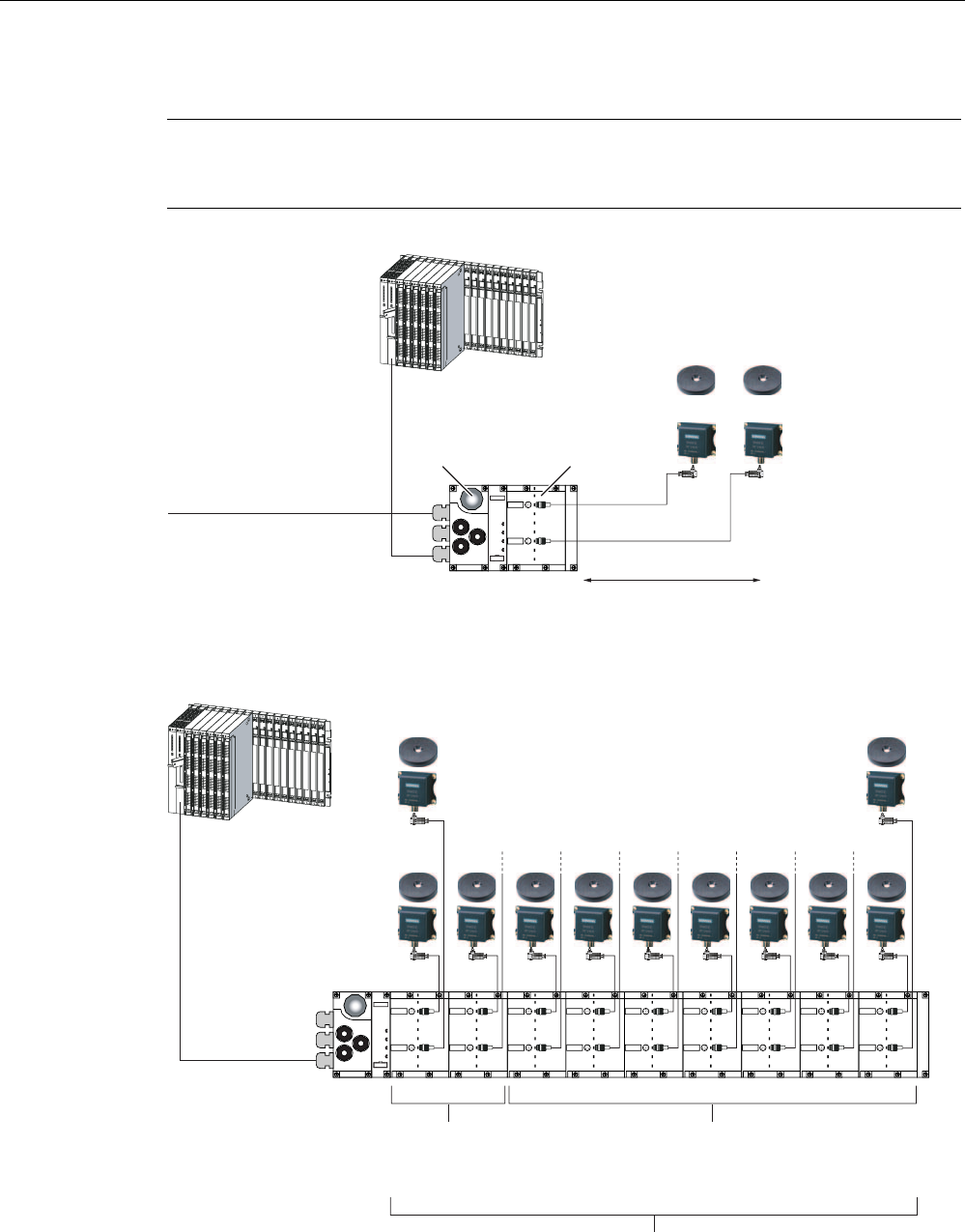
Configuration
Note
In the figures below, the ET 200pro with the CM IM DP Direct connection module represents
an example for the interface module.
352),%86'3
PDVWHUPRGXOH
HJ6&38
P
VWDQGDUGFDEOHOHQJWK
352),%86FDEOHWR
DOO
352),%86VODYHV
9IRU5)&
DQGUHDGHUZULWHUHDGGHYLFH
,QWHUIDFHPRGXOH
RIWKH(7SUR
5HDGHUZULWHUHDGGHYLFH
0'6
5)&
Figure 7-38 Configurator for an RF170C
WR5)&
:LWKDKLJK
GDWDYROXPH
WR5)&
7KHWLPHVIRU
FRPPDQGSURFHVVLQJ
PD\EHH[WHQGHG
0D[LPXP5)&FDQEH
RSHUDWHGLQDQ(7SUR
Figure 7-39 Maximum configuration of RF170C on an ET 200pro
Communication modules
7.7 RF170C
SIMATIC RF300
218 System Manual, 09/2007, J31069 D0166-U001-A5-7618
7.7.2 Connect the RF170C with the connection module
Introduction
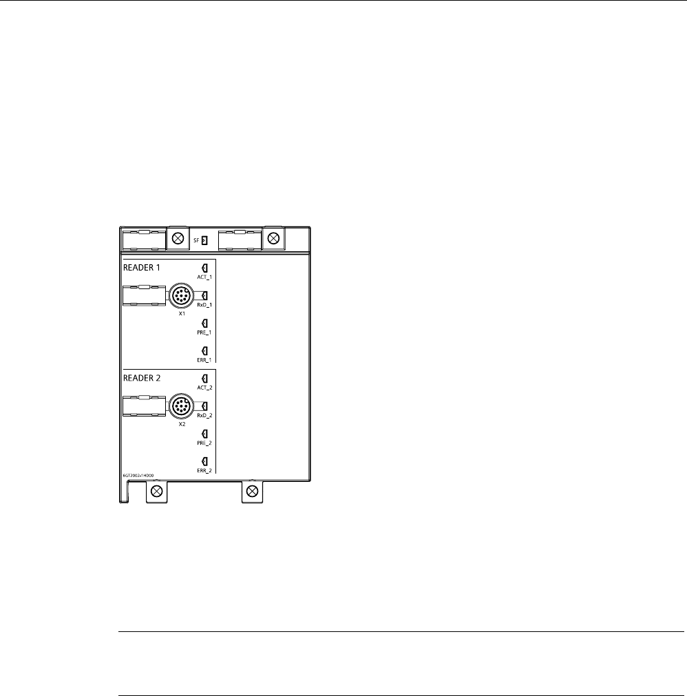
On the RF170C connection module, you connect the cable to the readers / write/read
devices using 8-pin round sockets. Use an 8-pin M12 connector and a corresponding cable if
you prefer to produce a customized cable.
In doing so, please comply with the cable configurator in the system manuals of the RFID
families.
Figure 7-40 Sockets and LEDs of the RF170C connection module
Requirements
Before you start to wire the RF170C connection module, switch off the supply voltage, or de-
install the connection module.
Note
It is easier to wire the RF170C connection module after you have removed it from the
communication module.
Accessories required for the RF170C
● Patch cable with 8-pin M12 connector
● Alternatively: Shielded 7-core Cu cable, flexible, conductor cross-section ≤ 0.75 mm2 and
8-pin M12 connector
Connecting M12 connectors
1. Plug the connector into the relevant socket of the RF170C connection module. Make sure
the connector and socket are properly interlocked (groove and spring).
2. Tighten the knurled screws of the connector (torque = 1.5 Nm.)
Communication modules
7.7 RF170C
SIMATIC RF300
System Manual, 09/2007, J31069 D0166-U001-A5-7618 219
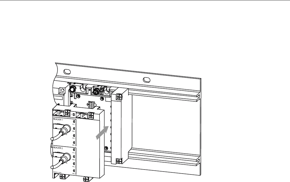
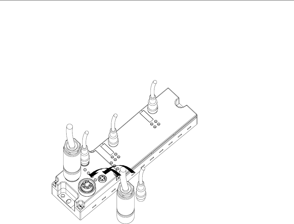
Connect RF170C connection module
1. Insert the RF170C connection module into the communication module.
2. Screw the connection module onto the rack (4 cross-head screws on the front: top and
bottom, tightening torque 1.5 Nm)
Figure 7-41 Connect RF170C connection module
Sealing unused sockets
Always close all unused sockets using M12 caps in order to achieve the degree of protection
IP65, IP66 or IP67.
Reference
ET 200pro Distributed I/O device
operating instructions, Section
Electrical configuration of
ET 200pro
Communication modules
7.7 RF170C
SIMATIC RF300
220 System Manual, 09/2007, J31069 D0166-U001-A5-7618
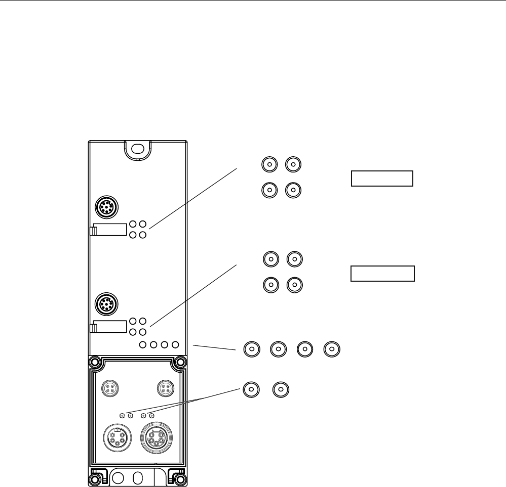
7.7.3 LED displays on the RF170C communication module
LED display
The figure below shows the position and layout of the LED display on the the RF170C
connection module.
Figure 7-42 LED display on the RF170C communication module

Communication modules
7.7 RF170C
SIMATIC RF300
System Manual, 09/2007, J31069 D0166-U001-A5-7618 221
Status and error LEDs on the RF170C connection module
Table 7-21 Status and error LEDs for RF170C
LEDs Meaning*
SF Group errors
ACT_1, ACT_2 The corresponding reader / (write/read device) is active in processing a user
command. (MOBY I only)
ERR_1, ERR_2 * A flashing pattern indicates the last error to occur.
PRE_1, PRE_2 ** Indicates the presence of a transponder/MDS.
RxD_1, RxD_2 Indicates live communication with the reader / write/read device. May also
indicate malfunctions on the reader / write/read device.
* The meaning of the individual flashing pattern is described in the relevant FB and FC
documentation. That documentation also includes the associated error descriptions.
** In the case of multitag operation, this LED uses a flashing interval to indicate the number of data
carriers currently within the range of the reader / write/read device.
After start-up or updating the firmware, the LEDs SF, PRE, ERR and ACT indicate the
operating status or faults of the RF170C:
SF PRE_1 ERR_1 ACT_1 PRE_2 ERR_2 ACT_2 Description
Off Off Off On Off Off Off Start-up active
On Off On Off Off Off Off Checksum error at start-up *
On Off Off Off Off On Off Firmware invalid *
On On On On On On On LED test for approximately 4 seconds;
otherwise firmware fault *
On Off On On Off On On Checksum error at start-up *
On On On On Off On On Checksum error of the firmware *
On Off On On On On On External RAM defective *
On On Off On On On On ESSA3 defective *
On Off On On On Off On ID error firmware *
– Off 1 x flash
every 3 s
Off Off 1 x flash
every 3 s
Off RF170C successfully started up, waiting
for reset command
– – n x flash
every 3 s
– – m x flash
every 3 s
– The number of flashes (n, m) indicates the
last reported error on a given channel.
– – Flashing Rapid
flashing
– Flashing Rapid
flashing
Firmware update; alternate flashing of the
error LEDs at approximately 1 Hz
– = not relevant
* If this fault recurs, the module is defective and must be replaced.

Communication modules
7.7 RF170C
SIMATIC RF300
222 System Manual, 09/2007, J31069 D0166-U001-A5-7618
7.7.4 Technical specifications
Table 7-22 Technical specifications for RF170C
Normal addressing Filehandler
Serial interface to the user PROFIBUS DP-V1/PROFINET IO
Interface to the ET 200pro ET 200pro backplane bus
Connection method See
ET 200pro
operating instructions
Transmission rate See
ET 200pro
operating instructions
Max. block length 2 words cyclic/240 bytes acyclic
(per channel)
Serial interface to the reader/ write/read device
Connector 2 x M12 coupler plug
Max. cable length 1000 m, dependent on reader / write/read device
(2 m = standard length; for other standard cables and self-
assembled cables, refer to Section
Connecting cables
)
Connectable readers / write/read
devices
2x reader / write/read devices
Software functions
Programming Depending on the PROFIBUS
DP master
Depending on the PROFIBUS
DP master
SIMATIC S7 function blocks FB 45 / FC 45
(normal addressing without
multitag)
FC 55
(normal addressing with
multitag)
FB 56 / FC 56
(filehandler, with and without
multitag)
MDS addressing Direct access via addresses Access via DOS-like file system
Commands Initialize MDS,
read data from MDS,
write data to MDS, etc.
Format MDS,
read file,
write file, etc
MOBY I dialog:
Normal station/VMDS
Memory size VMDS
Yes/Yes
16KB
No/No
–
Power supply 1
• Rated value 24 V DC
• Permissible range 20 V to 30 V DC
Current consumption 2 Max. 1 A; typ. 130 mA (without reader / write/read device)
Current taken from reader outputs max. 800 mA
(for one or 2 readers / write/read devices)
Galvanic isolation Yes
Ambient temperature
• During operation –25 to +55°C
• During transport and storage –40 to +70°C

Communication modules
7.7 RF170C
SIMATIC RF300
System Manual, 09/2007, J31069 D0166-U001-A5-7618 223
Normal addressing Filehandler
Dimensions (W x H x D) in mm
• RF170C (electronic and bus
module) 90 x 130 x 35
• RF170C with connection
module 90 x 130 x 60
Weight
• RF170C communication
module Approx. 270 g
• RF170C connection module Approx. 500 g
Degree of protection IP67
MTBF (at 40°C) 129 years
Approvals cULus (file E116536)
1) All supply and signal voltages must be low level protective voltage (SELV/PELV acc. to EN 60950)
24 V DC supply: Safety (electrical) isolation of low voltage (SELV / PELV acc. to EN 60950)
2) The current supply must provide the current required (max. 1 A) for intermittent periods of failed
voltage ≤ 20 ms.
Communication modules
7.7 RF170C
SIMATIC RF300
224 System Manual, 09/2007, J31069 D0166-U001-A5-7618
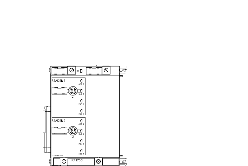
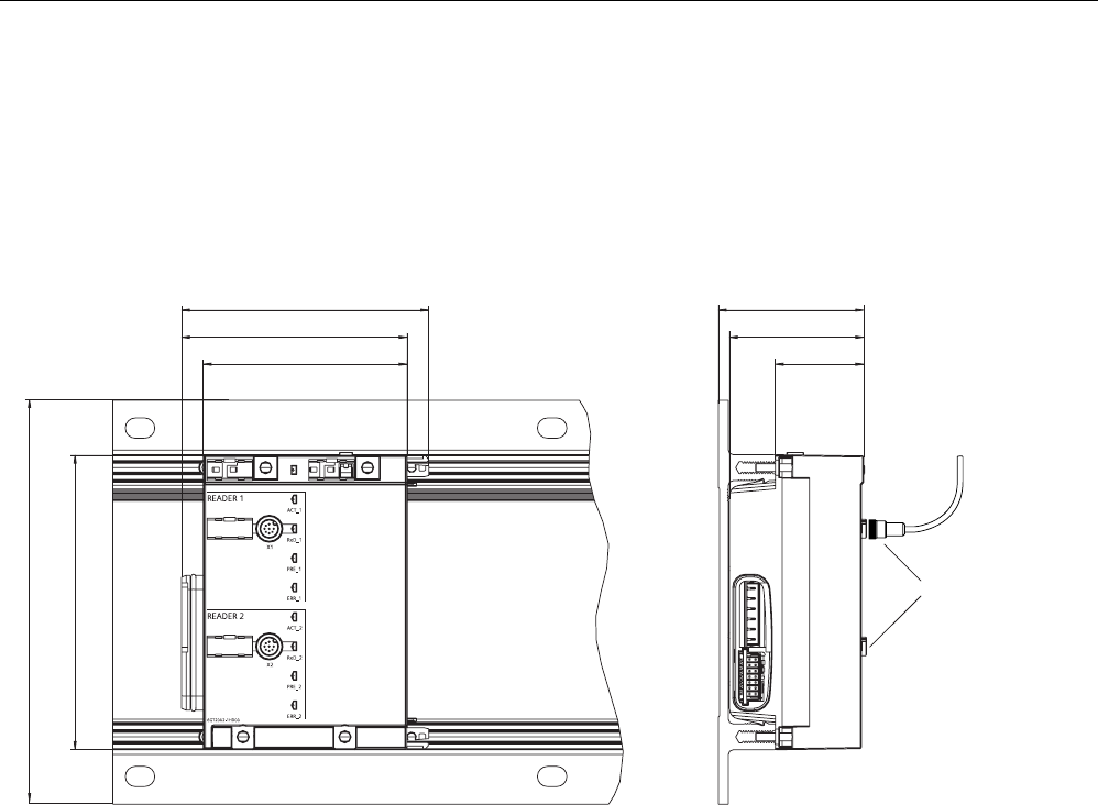
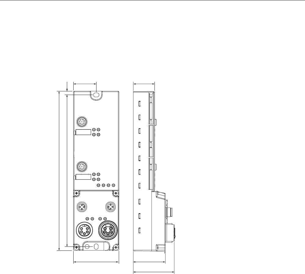
7.7.5 Dimensional drawings
RF170C with connection module
The dimension drawing for an RF170C communication module with plugged-in connection
module is shown below.
SF
5HDGHU
FRQQHFWLRQ
1RWHEHQGLQJ
UDGLXV
Figure 7-43 Dimension drawing for RF170C communication module with connection module on mounting rack, narrow
Communication modules
7.7 RF170C
SIMATIC RF300
System Manual, 09/2007, J31069 D0166-U001-A5-7618 225
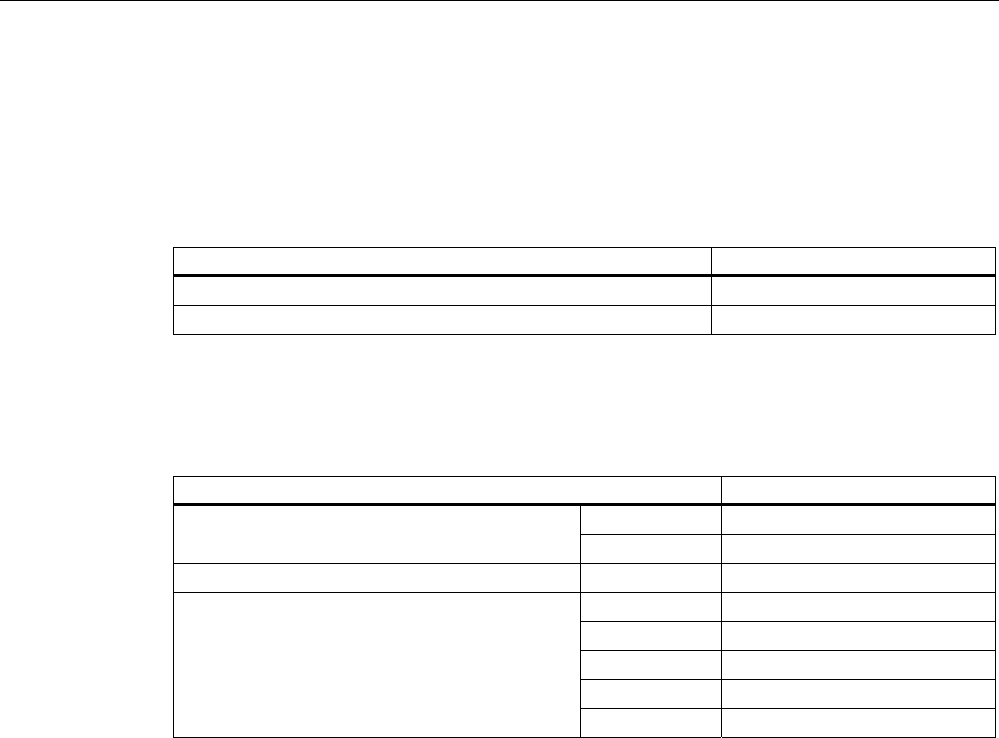
7.7.6 Ordering data
Communication module and connection module
Table 7-23 Communication module and connection module order numbers
Name Order number
RF170C communication module, 1 unit 6GT2002-0HD00
RF170C connection module, 1 unit 6GT2002-1HD00
RF170C connection module accessories
Table 7-24 Order numbers for RF170C connection module accessories
Name Order number
2.0 m 6GT2091-0FH20 Write/read device cable MOBY I / E / U
5.0 m 6GT2091-0FH50
Write/read device cable MOBY D 2.0 m 6GT2691-0FH20
2.0 m 6GT2891-0FH20
5.0 m 6GT2891-0FH50
10.0 m 6GT2891-0FN10
20.0 m 6GT2891-0FN20
Reader cable RF300, extension cable
RF300/MOBY I/E/U/D
50.0 m 6GT2891-0FN50
Communication modules
7.8 RF180C
SIMATIC RF300
226 System Manual, 09/2007, J31069 D0166-U001-A5-7618
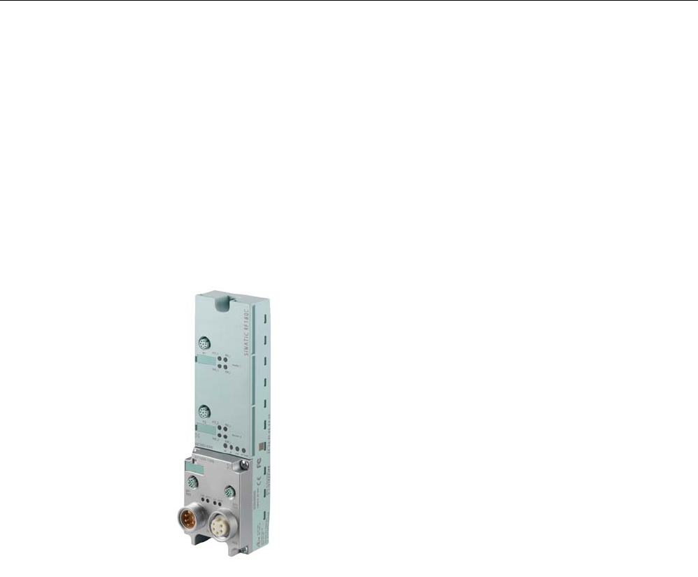
7.8 RF180C
7.8.1 Description
Area of application
The RF180C communication module is a module that can be used on any controller for
operating RFID components over PROFINET IO.
Figure 7-44 RF180C communication module
When operating the RF180C on a SIMATIC S7, a convenient function module is made
available to the user (FB 45). When using it on other controllers, please follow the
appropriate instructions for parameterization and integration in the system.
The following RFID families can be operated with the RF180C:
● RF300
● MOBY D
● MOBY U (normal addressing)
● MOBY E (available soon)
● MOBY I (available soon)

Communication modules
7.8 RF180C
SIMATIC RF300
System Manual, 09/2007, J31069 D0166-U001-A5-7618 227
Features
Up to two readers / SLGs can be operated on the RF180C at the same time. The user can
issue a command to 2 readers / SLGs simultaneously (FB 45 when operating on a SIMATIC
S7).
The tag data are accessed by means of physical addressing of the tag. In SIMATIC S7, the
FB 45 is available for this purpose. The FB 45 provides the S7 user with a simple-to-use
interface with powerful commands (processing one complete tag with one command;
command linking; S7 data structures via UDTs).
Other features
● Degree of protection IP67
● System integration with M12, 7/8" concept
● Standardized PROFINET IO user interface for identification systems with RFID standard
profile (with later firmware version)
● Firmware update
● Parameterizable device-specific diagnostics data
● Support for I&M functionality (a mechanism for reading out information via the module
and saving system information such as function, installation date, installation location,
and comments).
Communication modules
7.8 RF180C
SIMATIC RF300
228 System Manual, 09/2007, J31069 D0166-U001-A5-7618
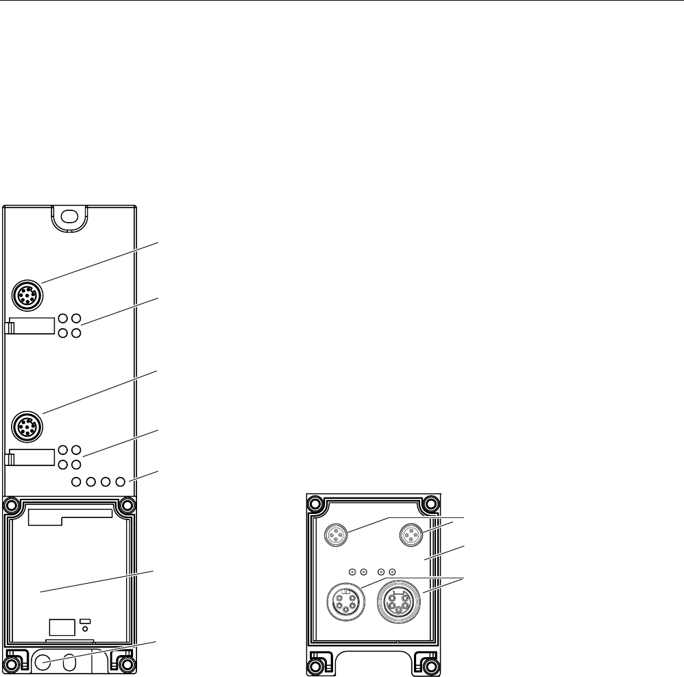
Layout
The RF180C has the same housing as the distributed I/O system ET 200eco.
For connecting to PROFINET IO, the RF180C communication module has a connection
block of the M12, 7/8" type.
The following figure shows the basic design of the RF180C.
&RQQHFWRUVRFNHWIRU
VWUHDGHU6/*
6SDFHIRUFRQQHFWLRQ
EORFN
6WDWXV/('VIRURSHUDWLRQRI
WKHQGUHDGHU6/*
6WDWXV/('VIRULQWHUIDFH
PRGXOH
6WDWXV/('VIRURSHUDWLRQ
RIWKHVWUHDGHU6/*
&RQQHFWRUVRFNHWIRU
QGUHDGHU6/*
3URWHFWLYH(DUWK
&RQQHFWLRQEORFN
&RQQHFWLRQVRFNHWV
IRU352),1(7,2
&RQQHFWLRQVRFNHWVIRU
YROWDJHVXSSO\
%DVLFXQLW
&RQQHFWLRQEORFN
;
;
*7-'
*7"-'
6,0$7,&5)&
[ [
[ [
Figure 7-45 Basic design of the RF180C
Communication modules
7.8 RF180C
SIMATIC RF300
System Manual, 09/2007, J31069 D0166-U001-A5-7618 229
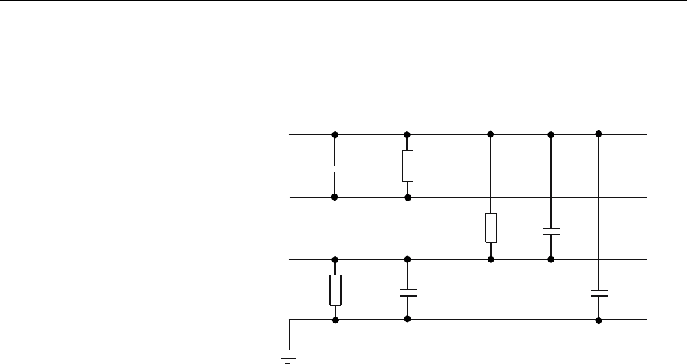
Potential
Ungrounded installation of the system is possible with the RF180C. The following circuit
shows the internal relationships of the reference potentials.
0˖
0˖
0˖
Q)
Q)
Q) Q)
0
0
0
6FKLUP
99HUVRUJXQJ
5)&XQG5HDGHU
,QWHUQH9HUVRUJXQJ
5HDGHU6FKQLWWVWHOOH
352),1(7,2
+LOIVVSDQQXQJI¾U
%XVDQVFKOXVV
Figure 7-46 Electrical isolation of RF180C
Communication modules
7.8 RF180C
SIMATIC RF300
230 System Manual, 09/2007, J31069 D0166-U001-A5-7618
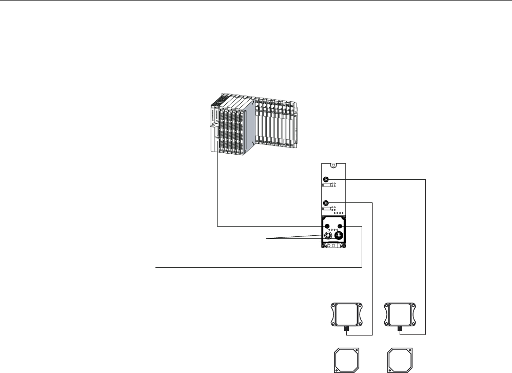
Integration
The following figure shows how the RF180C is integrated in an automation system.
6WHXHUXQJ
]%6&38
352),1(7,2/HLWXQJ
]XZHLWHUHQ
352),1(7,27HLOQHKPHUQ
9I¾U5)&XQG5HDGHU6/*
5HDGHU 5HDGHU
7UDQVSRQGHU
;
;
5)&
Figure 7-47 Configurator for RF180C
The RF180C is integrated into the hardware configuration by means of a GSDML file. The
RF180C can then be configured using HW-Config of the SIMATIC manager or another
PROFINET tool. The GSDML file can be found on the
RFID Systems Software &
Documentation
CD or on the Internet (see Section
Service & Support
).

Communication modules
7.8 RF180C
SIMATIC RF300
System Manual, 09/2007, J31069 D0166-U001-A5-7618 231
7.8.2 Connection
Proper use
When connecting non-specified devices to the RF180C, it is possible that the connected
device may be destroyed.
PROFINET IO connection system
Detailed information about connecting the RF180C to PROFINET IO can be found in the
PROFINET System Manual
.
You will find the system manual on the Internet at the following address:
http://www.siemens.com/automation/service&support
Search for the entry with the ID number 19292127.
NOTICE
The device must not be connected to the public telephone network without a HUB / Switch
because the voltage intervals are designed for 500 V.
Communication modules
7.8 RF180C
SIMATIC RF300
232 System Manual, 09/2007, J31069 D0166-U001-A5-7618
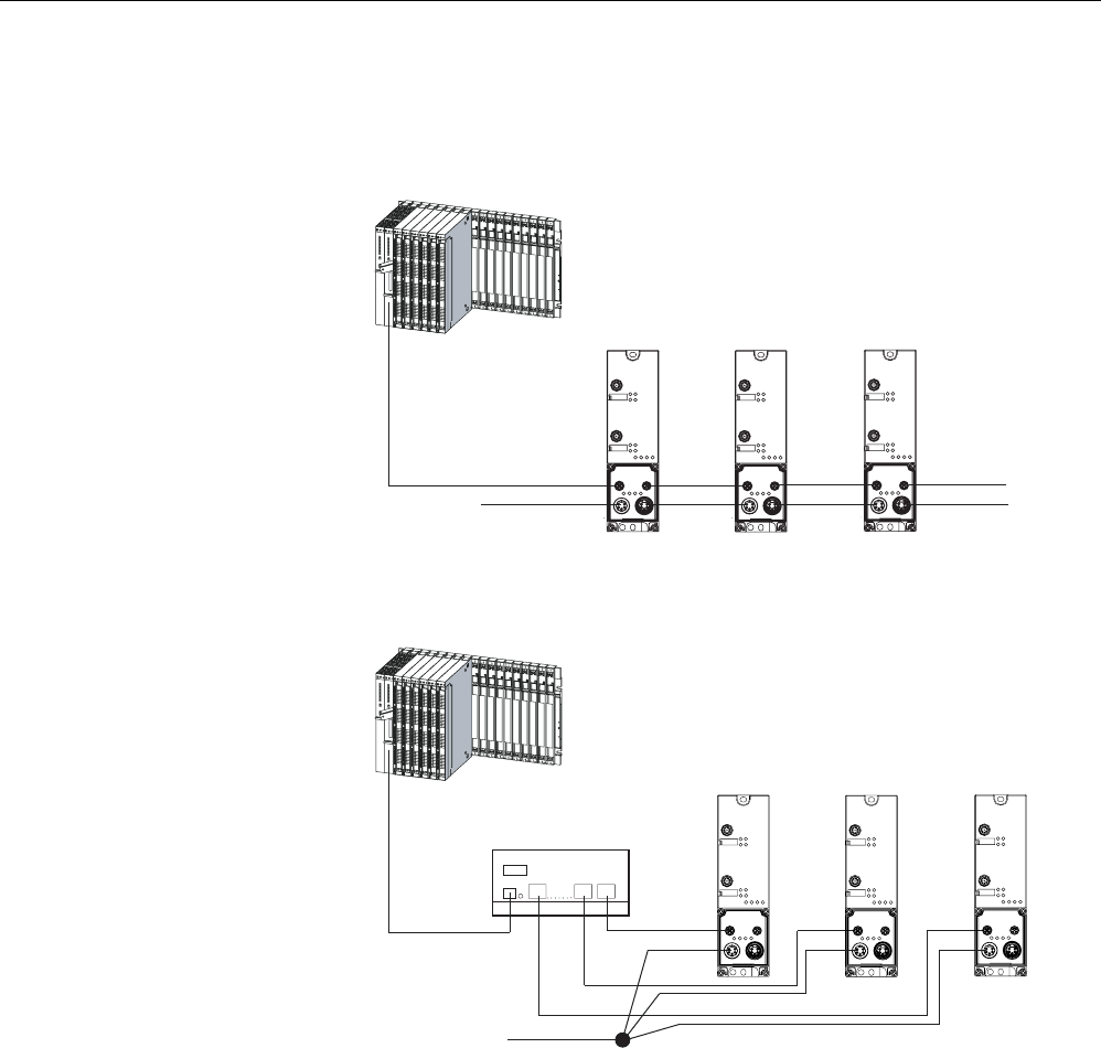
PROFINET IO installation techniques
PROFINET IO communication can be established in BUS or STAR topology. Please note the
information in the Section
Loop-through connection of PROFINET IO and supply voltage
.
3/&
HJ6&38
352),1(7,2FDEOH
9'&
5)& 5)& 5)&
Figure 7-48 RF180C with BUS topology
3/&
HJ6&38
352),1(7,2FDEOH
9'&
6ZLWFKHJ6&$/$1&(
5)& 5)& 5)&
Figure 7-49 RF180C with STAR topology
Communication modules
7.8 RF180C
SIMATIC RF300
System Manual, 09/2007, J31069 D0166-U001-A5-7618 233
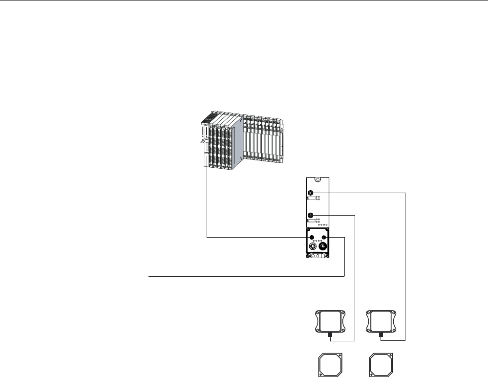
Reader/SLG connection system
One reader/SLG always occupies one M12 connection socket on the RF180C. A
preassembled cable therefore provides the optimum easy connection for the reader/SLG.
The connection cable is 2 m long in the standard version.
3/&
HJ6&38
352),1(7,2FDEOH
WRRWKHU
352),1(7,2VWDWLRQV
5HDGHU 5HDGHU
7UDQVSRQGHU
5)&
Figure 7-50 Overview of wiring

Communication modules
7.8 RF180C
SIMATIC RF300
234 System Manual, 09/2007, J31069 D0166-U001-A5-7618
7.8.2.1 Wiring connection block M12, 7/8"
Features
● Connect the supply voltages and PROFINET IO to connection block M12, 7/8":
– M12 connection in D coding: PROFINET IO
– 7/8" connection: Power supply voltages
● You can loop the supply voltages and PROFINET IO through via the second M12 or 7/8"
round socket.
Requirements
● Wire connection block M12, 7/8" when the supply voltage is switched off.
Required tools
Stripping tool, screwdriver for wiring the M12 and/or 7/8" connector if you are not using a
pre-assembled cable.
Accessories required
● Pre-assembled cable with connector
● If you are not using a pre-assembled cable:
– M12: 4-core Ethernet cable (Twisted Pair), shielded and M12 connector, 4-pole, D
coding (see Table
Pin assignments of M12 connector, 4-pole, D coding
(PROFINET IO)
)
– 7/8": 5-core cable and 7/8" connector (see Table
Pin assignment for 7/8" connector
(supply voltages)
)
● For order numbers, refer to Section
Ordering data
.
Communication modules
7.8 RF180C
SIMATIC RF300
System Manual, 09/2007, J31069 D0166-U001-A5-7618 235
Wiring M12, 7/8" connector
The tables below contain the pin assignment for the M12 and 7/8" connectors:
Table 7-25 Pin assignment for M12 connector, 4-pole, D coding (PROFINET IO)
Pin Assignment View of M12 connector, 4-pole, D coding
(wiring side)
1 Data line TxP
2 Data line RxP
3 Data line TxN
4 Data line RxN
(LQVSHLVHQXQG:HLWHUVFKOHLIHQ
352),1(7,2;;
(WKHUQHW.DEHO
7ZLVWHG3DLU
Any connector can be used for infeed and
looping through
Table 7-26 Pin assignment for 7/8" connector (supply voltages)
Pin Assignment View of 7/8" connector
(wiring side)
1 Load voltage ground (2M)
2 Ground for electronic / encoder supply
(1M)
3 PE
4 Electronics / encoder supply (1L+)
(voltage supply for RF180C and
reader/SLG)
5 Load voltage supply (2L+)
(unused on RF180C)
/
/
/
/
6XSSO\;
FRUHFDEO
/RRSWKURXJKFRQQHFWLRQ;
Note
When connecting up the supply voltage, we recommend the cable specified in the Section
Ordering data
(cable 5 x 1.5 mm2 pre-assembled with 7/8" connectors).
If you want to assemble the cable yourself, then the conductor cross-section should be
1.5 mm2.
Communication modules
7.8 RF180C
SIMATIC RF300
236 System Manual, 09/2007, J31069 D0166-U001-A5-7618
Connecting up M12, 7/8” connector
1. Press the connector (M12 or 7/8") into the relevant round socket on the connection block.
Ensure that the correct stop is provided between the connector and bush (groove and
spring).
2. Use the knurled locking ring to secure the connector.
6,0$7,&5)&
Figure 7-51 Connecting up M12, 7/8” connector
Sealing unused sockets
Always close all unused sockets using M12 or 7/8" seal caps in order to achieve the degree
of protection IP65, IP66 or IP67. For order numbers, refer to Section
Ordering data
.

Communication modules
7.8 RF180C
SIMATIC RF300
System Manual, 09/2007, J31069 D0166-U001-A5-7618 237
7.8.3 Parameter assignment
7.8.3.1 PROFINET IO configuration
Introduction
The GSDML file allows you to configure RF180C in STEP 7 V5.3 + SP 2 or higher. The
GSDML file must have been installed beforehand in the configuration software.
Requirements
● A GSDML file is required to integrate the RF180C into the hardware configuration of the
SIMATIC Manager:
GSDML-V1.0-SIEMENS-RF180C-"Datum im Format yyyymmdd".xml
You will find the file on the CD
RFID Systems Software & Documentation
in the directory
Daten\PROFI_GSD\RF180C
.
● The RF180C must have a valid IO device name. The default device name is RF180C
Configuring the RF180C on PROFINET IO with STEP 7
1. Start STEP 7, then select Options > Install New GSD File in HW Config.
2. Select the GSDML file to install from the next dialog box, then confirm with OK.
Result: The RF180C is displayed in the HW catalog under Profinet IO > Ident Systems >
SIMATIC RFID.
3. Create a new project.
4. Configure the RF180C in HW Config.
5. Parameterize the RF180C.
6. Save the configuration, or download it to the IO controller.
Further information can be found in the Sections
Assigning device names to the IO device
and
Configuration parameters of the RF180C
.

Communication modules
7.8 RF180C
SIMATIC RF300
238 System Manual, 09/2007, J31069 D0166-U001-A5-7618
7.8.3.2 Assigning device names to the I/O device
Introduction
Each PROFINET IO device is assigned a unique device ID by the manufacturer (MAC
address).
Each RF180C IO device is addressed by its device name in the configuration and user
program.
For detailed information on addressing in PROFINET IO, refer to the
PROFINET System
Description
.
Requirements
● RF180C communication module
● The PG must be online on PROFINET to the IO device to let you assign a device name to
the communication module.
● There must be no connection to the CPU.
Transferring the device name to the communication module
1. In HW Config select PLC > Ethernet > Edit Ethernet Node.
2. Click the <Search> button for modules that can be accessed online. This will display all
accessible IO controllers and IO devices complete with MAC address, IP address (where
applicable), device name and device type.
3. Select the required RF180C and click <OK>.
4. Assign a device name and click the button <Assign name>.
The device name must be unique within the plant and must comply with the HW Config
configuration.
Result
The device name is saved in connection block and base unit of the RF180C communication
module.
Forwarding the device name when the communication module is replaced
The device name of the IO device is saved in the connection block.
To transfer the device name when the RF180C communication module is replaced, remove
the connection block from the "old" RF180C and plug it into the "new" RF180C. The station
can be addressed again and will operate as before the replacement.

Communication modules
7.8 RF180C
SIMATIC RF300
System Manual, 09/2007, J31069 D0166-U001-A5-7618 239
Station flash test
If you use more than one IO device, the dialog also displays more than one IO device. In this
case, you should compare the MAC address of the device with the indicated MAC address
and select the proper IO device.
The identification of IO devices in a system is facilitated by a node flash test. The flash test is
activated as follows:
1. In the Edit Ethernet Node dialog, select one of the indicated IO devices.
2. Press the button <Flashing>.
On the selected IO device both "Link" and "RX/TX" LEDs flash on the connection block.
3. With <Stop Flashing> fliashing stops again.

Communication modules
7.8 RF180C
SIMATIC RF300
240 System Manual, 09/2007, J31069 D0166-U001-A5-7618
7.8.3.3 Configuration parameters of the RF180C
The GSDML file contains four parameters relevant to RFID that must be set. They are set by
selecting the "Object properties" for slot 0 of the RF180C in HW Config
The parameters are described in the function manual
FB 45
. The table below shows the
possible settings:
Table 7-27 Setting of RFID-relevant parameters
Parameter name Value Note
FB 45 Default
FB 55 With later firmware version
FB 56 With later firmware version
USER_Mode
RFID standard profile With later firmware version
MOBY I / E standard addressing With later firmware version
MOBY I file handler With later firmware version
MOBY U / D / RF300 standard
addressing
Default
MOBY_Mode
MOBY U file handler With later firmware version
19.2 k baud
57.6 k baud 1
Baud rate for write/read
device RF300 /
MOBY U/D 115.2 k baud Default 1
none Standard diagnostics only
Hard errors Hardware-related messages
only
Hard/soft errors low priority All messages
Diagnostics with diagnostics
messages (see
Diagnostics
chapter)
Hard/soft errors high priority All messages high-priority
1 not permitted with MOBY D with write/read device D11S/D12S

Communication modules
7.8 RF180C
SIMATIC RF300
System Manual, 09/2007, J31069 D0166-U001-A5-7618 241
7.8.3.4 Input parameters for RF180C
Input parameters for RF180C with FB 45
Allocation is undertaken in UDT 10.
Table 7-28 Input parameters for RF180C with FB 45
Address Name Permissible values Comment
+0.0 ASM_address 256, 260, 264, 268,
… Each RF180C occupies four bytes of
I/O in the I/O area of the control
unit
+2.0 ASM_channel 1, 2
+8.0 MDS_control B#16#0, 1 0 = no presence check
1 = presence check
+9.0 ECC_mode TRUE, FALSE
+9.1 RESET_long TRUE, FALSE TRUE,
if MOBY_mode = 5 (MOBY U)
+10.0 MOBY_mode B#16#1, 4, 5, 6, 7,
8, 9, A, B Special features of the MOBY I dialog
(8):
• Write/read device must be type
SLG4x.
• The VMDS memory size is 16KB. The
INIT command for the VMDS must be
specified using 4000 hex.
MOBY I:
B#16#00 … FF
+11.0 scanning_time
MOBY U:
B#16#00 … C8
The 00 value is only of any use if
the parameters for MOBY_mode have
been set accordingly.
+12.0 option_1 B#16#00, 02, 04
MOBY U (normal
output power):
B#16#05, 0A, 0F, 14,
19, 1E, 23
MOBY U (reduced
output power):
B#16#85, 8A, 8F, 94,
99, 9E, A3
+13.0 distance_limiting
MOBY D:
B#16#02 … 28
MOBY U / D
+14.0 multitag B#16#1 MOBY U / D
MOBY U:
B#16#0, 1, 2, 3
+15.0 field_ON_control
MOBY D:
B#16#0
MOBY U / D
MOBY U:
B#16#00 … FF
+16.0 field_ON_time
MOBY D:
B#16#00, 01
MOBY U / D

Communication modules
7.8 RF180C
SIMATIC RF300
242 System Manual, 09/2007, J31069 D0166-U001-A5-7618
7.8.3.5 Command table of the RF180C
Table of commands of the RF180C for standard addressing (FB 45)
Allocation is undertaken in UDT 20 using the "command" variable.
Table 7-29 Commands for RF180C with standard addressing
Command code
normal linked *
Description Available in
the RFID system
01 41 Describe MDS all
02 42 Read MDS; read fixed code all
03 43 Initialize MDS all
04 44 SLG status RF300/MOBY U/D
08 48 Switch off MDS MOBY U
0A 4A Turn antenna on/off RF300/MOBY U/D
0B 4B MDS status RF300/MOBY U
*) Chained commmands are not supported by all readers / SLGs. Please note the relevant
information in the RFID system manuals.
Communication modules
7.8 RF180C
SIMATIC RF300
System Manual, 09/2007, J31069 D0166-U001-A5-7618 243
7.8.4 PROFINET diagnostics
7.8.4.1 Diagnosis using LEDs
The following figure shows details of the LEDs of the RF180C.
[ [
[ [
/LQN 5;7;
6) %) 21 '&9
;
;
*7-'
6,0$7,&5)&
$&7B 35(B
5['B (55B
$&7B 35(B
5HDGHU6/*
5HDGHU6/*
5['B (55B
Figure 7-52 LEDs of the RF180C

Communication modules
7.8 RF180C
SIMATIC RF300
244 System Manual, 09/2007, J31069 D0166-U001-A5-7618
Table 7-30 Status LEDs for the RF180C
LEDs Meaning*
ON Lights up when the RF180C has completed start-up without errors.
24 VDC Lights up when the 24 V supply voltage is connected to the RF180C.
ACT_1, ACT_2 The corresponding reader/SLG is active in processing a user command.
ERR_1, ERR_2 * A flashing pattern indicates the last error to occur.
PRE_1, PRE_2 ** Indicates the presence of a tag/MDS.
RxD_1, RxD_2 Indicates live communication with the reader / SLG. May also indicate malfunctions on the
reader / SLG.
*) The meaning of the individual flash patterns and the associated fault descriptions can be found in the relevant FB
documentation.
**) In multitag mode, this LED uses a flash interval to indicate the number of data media currently within the range of
influence of the reader/SLG.
Table 7-31 LED display for PROFINET diagnostics
BF SF Cause of error Error handling
On – • Communication module is in start-
up mode.
• No cable inserted
When the bus is configured correctly, this state ends a
few seconds after switching the module on.
Flashes - • There is no connection to the IO
controller.
• Check the PROFINET IO connection.
• Check your PROFINET IO configuration (device
name, GSDML file).
• Reload the configuration into the RF180C (see the
Section "Configuration parameters of the RF180C")
Off On • A PROFINET diagnostic signal
exists.
• Analyze the diagnostic data.
Off Off • Normal mode –
– = Status not relevant
Table 7-32 LEDs on connection block
Link (green) Tx / Tx (yellow) Meaning
Off Off No physical connection over PROFINET IO
On Off Physical connection over PROFINET IO, no data communication
On Flashes Physical connection over PROFINET IO, with data communication
Off On Temporary state following switch-on
The table is applicable to both left and right PROFINET IO connection.
Other communication module operating modes are indicated by the PRE, ERR, ACT, SF
and ON LEDs:

Communication modules
7.8 RF180C
SIMATIC RF300
System Manual, 09/2007, J31069 D0166-U001-A5-7618 245
Table 7-33 LED display for operating states
ON BF SF PRE_1 ERR_1 ACT_1 PRE_2 ERR_2 ACT_2 Description
Off Off Off Off Off Off Off Off Off Start-up active
On On On On On On On On On LED test on start-up
(start PROFINET IO)
Off Off On On On Off On On Off Internal fault
Off Off On On Off On On Off On Checksum error of the firmware
Off Off On Off Slow
flashin
g
Off Off Slow
flashin
g
Off Firmware update
(flashes with every described area)

Communication modules
7.8 RF180C
SIMATIC RF300
246 System Manual, 09/2007, J31069 D0166-U001-A5-7618
7.8.4.2 Parameterization of the diagnostics
● Faults are reported by PROFINET IO through the generation of alarms. Alarms are output
using OB82. The alarm data can be accessed through
SFB 54
.
Parameterizing possibilities
See also Section
Configuration parameters of RF180C
.
● None
An alarm will not be issued in the event of an error.
● Hard errors
Alarms are generated in the case of the following events:
– Hardware fault (memory test)
– Firmware fault (checksum)
– Interrupted connection to the reader/SLG
An alarm is generated and the SF LED on the S7 CPU is activated.
● Hard/soft errors low priority
In contrast to hard errors, in this case, errors are also reported that arise during command
processing
An alarm is generated. However the SF LED on the S7 CPU is activated.
● Hard/soft errors high priority
As under hard/soft errors low priority
An alarm is generated when an event occurs as well as when the event ceases.
Incoming alarm
An event occurs and triggers an alarm. The SF LED of the S7 CPU is set as parameterized.
Outgoing alarm
An event no longer exists, an alarm is triggered and the SF LED of the S7 CPU is reset.
For events that only exist momentarily, the reset is delayed by 3 seconds.

Communication modules
7.8 RF180C
SIMATIC RF300
System Manual, 09/2007, J31069 D0166-U001-A5-7618 247
Further information
Detailed information about PROFINET IO diagnostics is included in the following documents:
● System manual
PROFINET, System Description
(Article No. 19292127)
● Programming manual
PROFINET IO, from PROFIBUS DP to PROFINET IO
(Article No. 19289930)
● Product information
PROFINET IO, Structure of the Diagnostic Data Records
(Article No. 19327300)
You will find the documents on the Internet at:
http://www.siemens.com/automation/service&support
Search for the specified article numbers here.

Communication modules
7.8 RF180C
SIMATIC RF300
248 System Manual, 09/2007, J31069 D0166-U001-A5-7618
7.8.4.3 Structure of the diagnostic data
The header of a diagnostic data record comprises 20 bytes of PROFINET IO-specific data.
The manufacturer-specific diagnostic data start from Byte 21.
For the RF180C, the diagnostic data are structured in accordance with the PROFIBUS
Profile Guideline (PROFIBUS Proxy Guideline, Identification Systems Proxy Ident Function
Block) for identification systems with MOBY-specific additional information.
Byte Name Contents
PROFIBUS Profile Guideline for Identification Systems
20 channel_num Bit 7..0 1d: Relating to Reader 1
2d: Relating to Reader 2
21 function_num Reserved for a future expansion stage
22 error_decode Reserved for a future expansion stage
23 error_code_1 Reserved for a future expansion stage
24 error_code_2 Reserved for a future expansion stage
RFID-specific additional information
25 moby_code_1 Reserved for a future expansion stage
26 moby_code_2 Reserved for a future expansion stage
27 moby_code_3 Reserved for a future expansion stage
28 moby_code_4 Error code
To be taken from the corresponding FC/FBs.
29 meldecode Error code
To be taken from the corresponding FC/FBs.
30 counter_high Continuous event counter high-order byte
31 counter_low Continuous event counter low-order byte
32 fw_version_high Firmware version high-order byte
33 fw_version_low Firmware version low-order byte

Communication modules
7.8 RF180C
SIMATIC RF300
System Manual, 09/2007, J31069 D0166-U001-A5-7618 249
7.8.5 Technical data
Table 7-34 General technical data
Ethernet interface to the user
Principle PROFINET IO
Physical medium Ethernet over 4-core cable
Duty type 100BaseX full duplex
Transmission rate 100 Mbit/s
Plug-in connection M12, 4-pin, D coding
Maximum cable length 100 m
Cable type STP Cat 5
Autonegotation Yes
Autocrossing Yes
Switch function Yes, internal
IRT No
RT Yes
Manufacturer ID (vendor ID) 002AH
Device ID (DeviceID) 0C01H
Serial interface to the reader/SLG
Connector 2 x M12 coupler plug
Max. cable length 1000 m, dependent on Reader/SLG
(2 m = standard length; for other standard cables and self-
assembled cables, refer to Section
Connection cables
)
Connectable readers/SLGs 2x readers / SLGs of the RFID families RF300, MOBY D or
MOBY U
Software functions
Programming Depending on the IO controller
SIMATIC S7 function blocks FB 45 (normal addressing without multitag)
Tag/MDS addressing Direct access via addresses
Commands Initialize tag, read data from tag, write data to tag, etc.
Supply voltage1)
Rated value 24 V DC
Permissible range 20 V to 30 V DC
Current consumption without
reader / SLG 2)
max. 500 mA; typ. 100 mA
Current consumption through reader
connection
Each 500 mA
Galvanic isolation Yes
Ambient temperature
During operation 0 to +60 °C
Transport and storage –40 to +70 °C

Communication modules
7.8 RF180C
SIMATIC RF300
250 System Manual, 09/2007, J31069 D0166-U001-A5-7618
Dimensions (W x H x D) in mm
Base unit only 60 x 210 x 30
Base unit with M12, 7/8" connection
block
60 x 210 x 54
Weight
Base unit Approx. 210 g
M12, 7/8" connection block Approx. 230 g
Mechanical Environmental Conditions
Vibration during operation According to IEC 61131-2:
0.75 mm (10Hz to 58 Hz)
10 g (58 Hz to 150 Hz)
Shock resistance, shock during
operation
Acc. to IEC 61131-2:
30 g
Degree of protection IP67
MTBF (Mean Time Between Failures) in years
Base unit 121
Connection block 1100
Approvals cULus (file E116536)
FCC Code of Federal Regulations,
CFR 47, Part 15,
Sections 15.107 and 15.109 (Class A)
1) All supply and signal voltages must be low level protective voltage (SELV/PELV acc. to
EN 60950)
24 V DC supply: Safety (electrical) isolation of low voltage (SELV / PELV acc. to
EN 60950)
2) The current supply must provide the current required (max. 500 mA) for intermittent
periods of failed voltage ≤ 20 ms.
Communication modules
7.8 RF180C
SIMATIC RF300
System Manual, 09/2007, J31069 D0166-U001-A5-7618 251
7.8.6 Dimension drawing for RF180C with fixing holes
The following figure shows the dimension drawing of an RF180C with bus connection block
M12, 7/8" PN.
[
[
6,0$7,&5)&
[ [
[ [
Figure 7-53 Dimension drawing for RF180C
Communication modules
7.8 RF180C
SIMATIC RF300
252 System Manual, 09/2007, J31069 D0166-U001-A5-7618
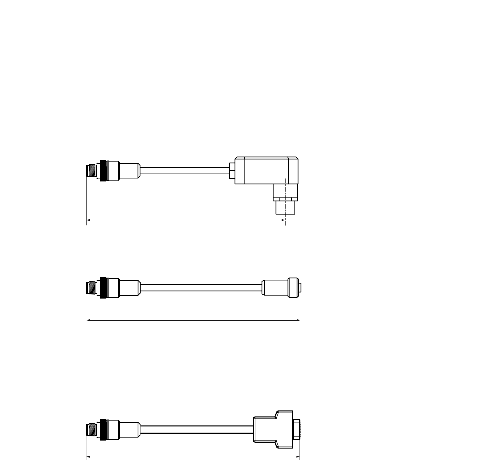
7.8.7 Connecting cable to the reader/SLG
7.8.7.1 Routing of standard cables
Available cables
O
Figure 7-54 Connecting cable M12 ↔ Reader / SLG; l = 2 m, 5 m (MOBY I / E / U)
O
Figure 7-55 Connecting cable/extension cable M12 ↔ M12; l = 2 m, 5 m, 10 m, 20 m, 50 m
● RF300 connecting cable
● Extension cable for all RFID systems
P
Figure 7-56 Connecting cable M12 ↔ sub-D (MOBY D)
Maximum cable length
The RF180C can be operated with any reader/SLG configuration with a maximum cable
length of 50 m.
Longer connecting cables of up to 1000 m are possible in some instances. The current
consumption of the connected reader/SLG must however be taken into account. You will find
information in the relevant system manuals.
Sequential arrangement of more than two sub-sections to form a long section of cable
should be avoided due to the additional contact resistances.
Communication modules
7.8 RF180C
SIMATIC RF300
System Manual, 09/2007, J31069 D0166-U001-A5-7618 253
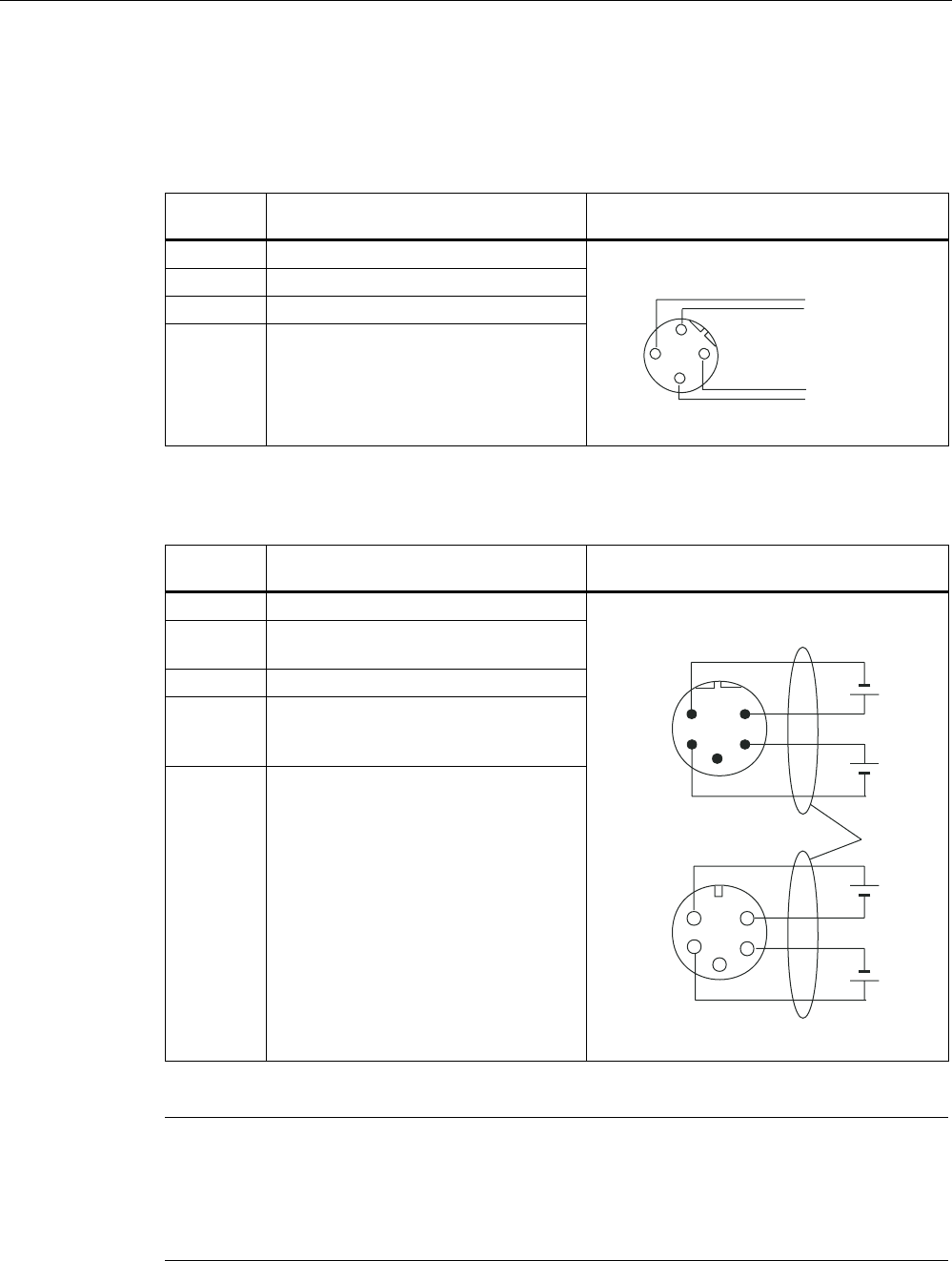
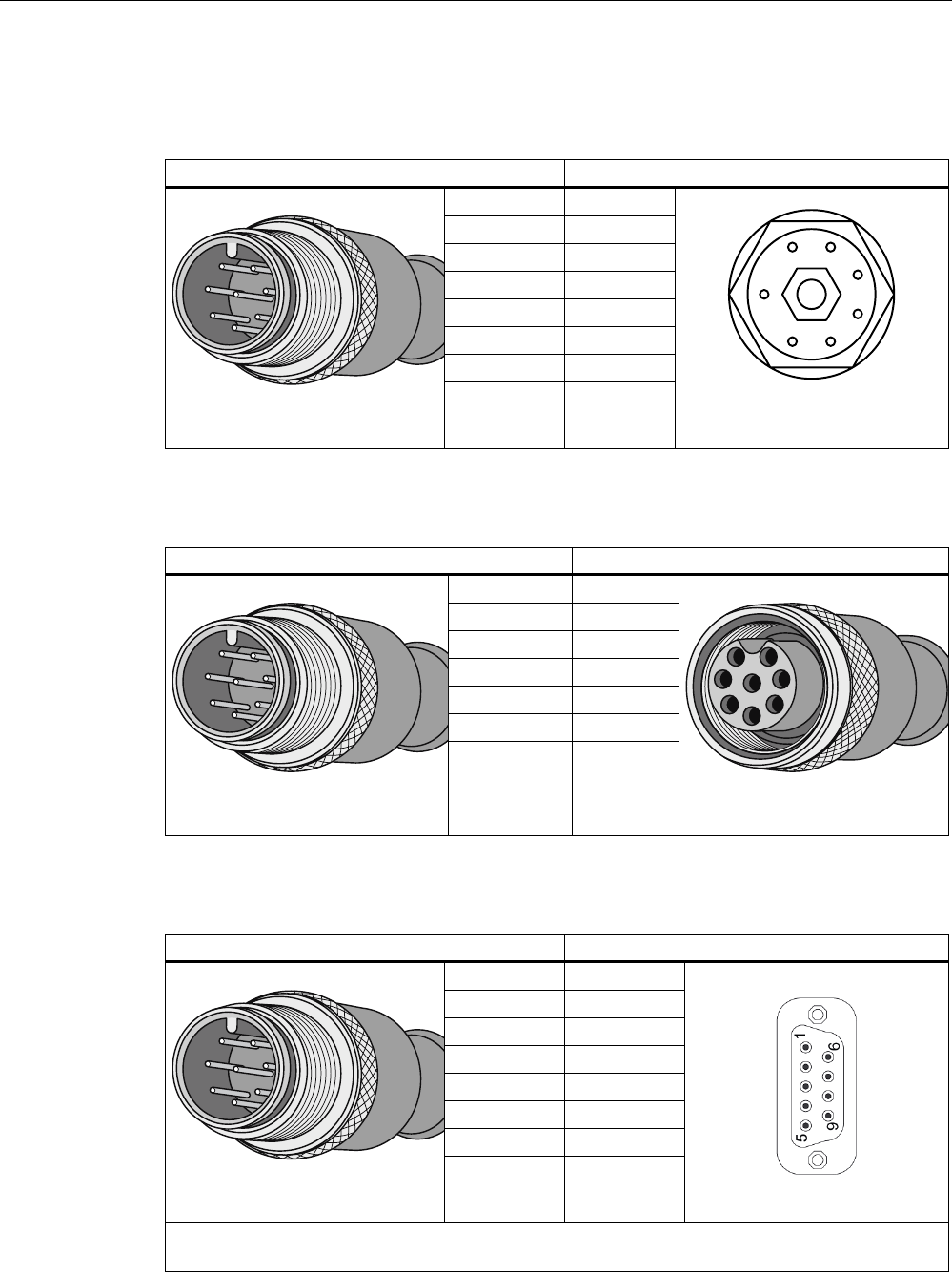
Pin assignment
Table 7-35 Connecting cable M12 ↔ Reader / SLG
M12 connector (male) Reader/SLG connector (female)
1 2
2 5
3 3
4 4
5 6
6 1
7 –
8 7
Table 7-36 Connecting cable / extension cable M12 <-> M12
1 1
2 2
3 3
4 4
5 5
6 6
7 7
8 8
Table 7-37 Connecting cable M12 ↔ sub-D 9-pin
M12 connector (male) Sub-D connector (female)
1 –
2 5
3 7
4 3
5 2
6 6
7 –
8 1, 8
Note:
Reader/SLG with Sub-D connector must be supplied over an additional connector with 24 V DC.
Communication modules
7.8 RF180C
SIMATIC RF300
254 System Manual, 09/2007, J31069 D0166-U001-A5-7618
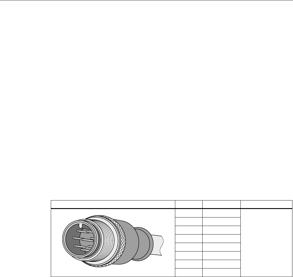
7.8.7.2 Self-assembled cable
A reader/SLG connector plug with screw terminals is provided for users who want to
individually pre-assemble their own cables (refer to the relevant system manual). Cables and
reader/SLG connector plugs can be ordered from the Catalog
FS 10 Sensors for Production
Automation
.
Cable structure
You will need cables of the following specifications for self-assembled cables:
7 x 0.25 mm2
LiYC11Y 7 x 0.25
Connectors
M12 connectors can be obtained from the relevant specialist dealers (e.g. Binder).
Pin assignment
The pin assignment is listed in the following table.
Table 7-38 Pin assignment
M12 connector (male) Pin Signal Core color
1 1L+ (+ 24 V)
2 −RxD
3 0 V
4 RxD
5 TxD
6 −TxD
7 Free
8 PE / shield
Note data sheet
provided by cable
manufacturer

SIMATIC RF300
System Manual, 09/2007, J31069 D0166-U001-A5-7618 255
System diagnostics 8
8.1 Error codes
Error codes of the RF300 readers
Flashing of red
LED on reader
Error code
(hexa-
decimal)
Description
00 00 no error
01 0F Boot message
02 01 Presence error, possible causes:
• The active command was not carried out completely
• The tag has left the field while the command is being processed
• Communication fault between reader and tag
05 05 Parameterization error, possible causes:
• Unknown command
• Incorrect parameter
• Function not allowed
06 06 Air interface faulty
12 0C The tag memory cannot be written, possible causes:
• Hardware fault (memory faulty)
• Memory write-protected (corresponding OTP area has already
been written)
13 0D Error in the specified memory address (access attempted to non-
existent or non-accessible memory areas).
19 13 Buffer overflow: Insufficient buffer available in the reader for saving
the command
20 14 Major system fault (hardware fault)
21 15 Parameter assignment error: faulty parameter in RESET command
25 19 Previous command is still active
28 1C Antenna is already switched off/Antenna is already switched on,
mode in SET-ANT command not recognized.
30 1E Incorrect number of characters in frame
31 1F Running command cancelled by "RESET" command

System diagnostics
8.2 Diagnostics functions
SIMATIC RF300
256 System Manual, 09/2007, J31069 D0166-U001-A5-7618
8.2 Diagnostics functions
8.2.1 Overview
Extended diagnostic functions with SIMATIC RF300
With SIMATIC RF300, extended diagnostic functions are available which simplify start-up
and maintenance.
These diagnostic data are accessed using the FC 45 function with the SLG STATUS and
MDS STATUS commands. These two commands can each be called in various modes
(subcommands) for which corresponding data structures (UDTs) are defined.
Command Mode
(subcommand)
Meaning
01 Hardware and firmware configuration, parameterization statusSLG STATUS
06 Communication error counter, current command status
01 Serial number of the tag (UID), memory configuration
EEPROM write-protection status
MDS STATUS
02 Serial number of the tag (UID), HF field strength value,
communication error counter, presence counter (duration)
Overview of the diagnostic functions

System diagnostics
8.2 Diagnostics functions
SIMATIC RF300
System Manual, 09/2007, J31069 D0166-U001-A5-7618 257
8.2.2 Reader diagnostics with SLG STATUS
The SLG STATUS command can be used to scan the status and diagnostics data of the
reader.
SLG STATUS (mode 01), UDT110
HW ASCII Type of hardware
(31 to 38 hex)
HW-V Binary value HW version
0 to FF hex
0 to FF hex
= Version (high byte): Unused
= Version (low byte)
Url-V Binary value Version of loader
0 to FF hex
0 to FF hex
= Version (high byte)
= Version (low byte)
FW ASCII format Type of firmware
FW-V Binary value Firmware version
0 to FF hex
0 to FF hex
= Version (high byte)
= Version (low byte)
TR Binary value Type of driver "1" = 3964R
TR-V Binary value Version of driver
0 to FF hex
0 to FF hex
= Version (high byte)
= Version (low byte)
SS Binary value RS232 / RS422
01 hex
= RS422
Baud Binary value Baud rate
01 hex
02 hex
05 hex
= 19.2 Kbaud
= 57.6 Kbaud
= 115,2 Kbaud
mtag Binary value Number of MDSes (Multitag/Bulk)
that can be processed in the
antenna field
= 1 with single-tag mode (param =
0x05, 0x25)
ANT Binary value Status of antenna
01 hex
02 hex
= Antenna On
= Antenna Off
ANW Binary value Presence mode
0
01 hex
= Operation without presence
= Operation with presence (see
ANW-MELD signal)

System diagnostics
8.2 Diagnostics functions
SIMATIC RF300
258 System Manual, 09/2007, J31069 D0166-U001-A5-7618
SLG STATUS (mode 06), UDT280
FZP Binary
value
0 … 255 = Error counter, passive (errors
during idle time)
ABZ Binary
value
0 … 255 = Abort counter
CFZ Binary
value
0 … 255 = Code error counter
SFZ Binary
value
0 … 255 = Signature error counter
CRCFZ Binary
value
0 … 255 = CRC error counter
BSTAT Binary
value
0 … 255 = Current command status
ASMFZ Binary
value
0 … 255 = Interface problems to host
(ASM/PC) parity, BCC, frame error
Note
All counter values are reset after reading (= SLG STATUS command executed).
Explanations:
● "FZP": Counts interference pulses when communication is not taking place with a
transponder. (e.g. EMC interference caused by contactors, motors, etc.). Counter values
can also be generated when a tag is located at the edge of the field even when there is
no external interference.
● "ABZ", "CFZ", "SFZ" and "CRCFZ" are protocol error counters that can be generated
during reader/tag communication. This can be caused by unsuitable reader/tag
positioning (e.g. tag on field boundary, several data carriers in the field) or external
electromagnetic interference.
To ensure clear diagnosis of the quality of communication, it is recommended that an SLG
STATUS command (mode 06) is executed following receipt of the presence command to
reset the error counter.
The protocol error counters are not mutually independent. If a code error (CFZ) occurs, this
will cause a secondary signature (SFZ) or CRC (CRCFZ) error.
● "BSTAT" is the status for the most recently executed command. A value other than 0
means that the previous command was repeated by the reader due to faults (see above).
● "ASMFZ" signals line-conducted communication interference between the communication
module (ASM) and the reader. Faults of this type can be caused by contact problems on
the connector or the cable connection.

System diagnostics
8.2 Diagnostics functions
SIMATIC RF300
System Manual, 09/2007, J31069 D0166-U001-A5-7618 259
8.2.3 Transponder diagnostics with MDS STATUS
The MDS STATUS command can be used to scan the status and diagnostics data of the
transponder that is located within the antenna field.
MDS STATUS (mode 01), UDT260
UID Binary value 0 … 264 -1 = b0-31: 4 byte TAG ID, b32-63: 0
MDS type Binary value 0x01
0x02
0x03
= Transponder without FRAM
= Transponder with FRAM 8 KB
= Transponder with FRAM 32 KB
Lock status Binary value 0 … 255 = Content of lock-bit register (EEPROM addr. 0xFF18)
MDS STATUS (mode 02), UDT270
LFD Binary value 0 … 255 = Value for field strength
FZP Binary value 0 … 255 = Error counter (passive) ➙ errors during idle time
FZA Binary value 0 … 255 = Error counter (active)
ANWZ Binary value 0 … 255 = Presence counter
Note
All counter values are reset when the tag exits the field or when the antenna is switched off.
Notes:
● "LFD" is a value for the field strength that is determined in the transponder. The lower the
value, the higher the field strength. A setpoint of < 28 hex signals reliable data transfer.
● "FZP" counts fault pulses when communication with a transponder is not taking place
(e.g. electromagnetic interference caused by contactors, motors, etc.). Counter values
can also be generated when a transponder is located at the edge of the field even when
there is no external interference.
● "FZA" counts errors that can occur during reader-to-transponder communication. This can
be caused by unsuitable reader/transponder positioning (e.g. transponder on field
boundary, several data carriers in the field) or external electromagnetic interference.
● "ANWZ" is the value for the time that the transponder remains in the field before the MDS
STATUS command (mode 02) is executed. A time step is 10 ms. The maximum time that
can be recorded is therefore 2.5 s.

System diagnostics
8.2 Diagnostics functions
SIMATIC RF300
260 System Manual, 09/2007, J31069 D0166-U001-A5-7618
SIMATIC RF300
System Manual, 09/2007, J31069 D0166-U001-A5-7618 261
Accessories 9
9.1 RFID Systems Software & Documentation
Version 3.0 and higher of the "RFID Systems Software & Documentation" product is supplied
on CD. All the required function blocks and drivers as well as the documentation for the
RFID systems are included.
● FC 35: S7 function for the 8xIQ-Sense module
● FB 240: Function block for ASM 450; MOBY on PROFIBUS DP via SIMATIC S5
(including device data file for PROFIBUS DP)
● FB 250: Function block for ASM 400
● FB 41 contains a function block for the ASM 410. The call interface of the FB is virtually
identical to FB 250. Please refer to the description of FB 250 for programming
instructions.
● FC 44 can be used to operate the ASM 450 in a SIMATIC S7 environment. It is essential
to read the instructions in the "Readme" file in the FC 44 directory. The "FC 44 for ASM
450" description is available for operation of the ASM 450.
● FC 45: S7 function for the ASM 754
● Function FC 47 for ASM 470
● FB 47 contains a function block for SIMATIC S5 115U - 155U. It can be used to operate
the ASM 470 in a SIMATIC S5 environment via an ET 200M.
● Load program for ES 030 and device data file for connection of the ES 030 to PROFIBUS
DP
● Test and demo programs for demonstrating the "read from MDS" and "write to MDS"
functions etc. on a PC (Windows). The ASM 424/724 MOBY modules and SIM are
connected to the PC (COM 1 or COM 2) by cable (with serial interface).
● 3964R driver for DOS, Windows 95 and Windows NT
● C library for CCT32 for Windows 95/NT 4.0
● C library for MOBY API for Windows 98/NT 4.0
● Latest edition of MOBY documentation in PDF format
● Tools: You will find utility programs for RFID system configuration here.

Accessories
9.1 RFID Systems Software & Documentation
SIMATIC RF300
262 System Manual, 09/2007, J31069 D0166-U001-A5-7618
The "RFID Systems Software & Documentation" CD has a user-friendly interface based on
HTML. After Start.exe has been called, a window for selecting the RFID system appears:
● RF300
● RF600
● RF-MANAGER
● MOBY
● CM/ASM
After selecting the RFID system, you can navigate to the required information.
Note
Notes on "RFID system software" and licensing
When purchasing a communication module or an interface module, no software or
documentation is supplied. The "RFID Systems Software & Documentation" CD-ROM
contains all available FBs/FCs for the SIMATIC, C libraries, demo programs, etc. and needs
to be ordered separately. In addition, the CD-ROM contains the complete RFID
documentation (German, English and French) in PDF format.
The purchase of a communication module or an interface module includes a payment for the
use of the software, including documentation, on the "RFID Systems Software &
Documentation" CD-ROM and the purchaser acquires the right to make copies (copy
license) insofar as they are required as part of the customer-specific application or
development for the plant.
The enclosed contract pertaining to the use of software products against a one-off payment
shall apply in addition.
SIMATIC RF300
System Manual, 09/2007, J31069 D0166-U001-A5-7618 263
Appendix A
A.1 Certificates and Approvals
DIN ISO 9001 certificate
The quality assurance system for the entire product process (development, production, and
marketing) at Siemens fulfills the requirements of ISO 9001 (corresponds to EN29001:
1987).
This has been certified by DQS (the German society for the certification of quality
management systems).
EQ-Net certificate no.: 1323-01
Appendix
A.1 Certificates and Approvals
SIMATIC RF300
264 System Manual, 09/2007, J31069 D0166-U001-A5-7618
Certifications for the United States, Canada, and Australia
Safety
One of the following markings on a device is indicative of the corresponding approval:
Underwriters Laboratories (UL) per UL 60950 (I.T.E) or per UL 508 (IND.CONT.EQ)
Underwriters Laboratories (UL) according to Canadian standard C22.2 No. 60950
(I.T.E) or C22.2 No. 142 (IND.CONT.EQ)
Underwriters Laboratories (UL) according to standard UL 60950, Report E11 5352 and
Canadian standard C22.2 No. 60950 (I.T.E) or UL508 and C22.2 No. 142
(IND.CONT.EQ)
UL recognition mark
Canadian Standard Association (CSA) per Standard C22.2. No. 60950 (LR 81690) or
per C22.2 No. 142 (LR 63533)
Canadian Standard Association (CSA) per American Standard UL 60950 (LR 81690) or
per UL 508 (LR 63533)

Appendix
A.1 Certificates and Approvals
SIMATIC RF300
System Manual, 09/2007, J31069 D0166-U001-A5-7618 265
EMC
USA
Federal Communications
Commission
Radio Frequency
Interference Statement
This equipment has been tested and found to comply with the limits for a
Class A digital device, pursuant to Part 15 of the FCC Rules. These limits
are designed to provide reasonable protection against harmful
interference when the equipment is operated in a commercial
environment. This equipment generates, uses, and can radiate radio
frequency energy and, if not installed and used in accordance with the
instruction manual, may cause harmful interference to radio
communications. Operation of this equipment in a residential area is likely
to cause harmful interference in which case the user will be required to
correct the interference at his own expense.
Shielded Cables Shielded cables must be used with this equipment to maintain compliance
with FCC regulations.
Modifications Changes or modifications not expressly approved by the manufacturer
could void the user's authority to operate the equipment.
Conditions of Operations This device complies with Part 15 of the FCC Rules. Operation is subject
to the following two conditions: (1) this device may not cause harmful
interference, and (2) this device must accept any interference received,
including interference that may cause undesired operation.
CANADA
Canadian Notice This Class B digital apparatus complies with Canadian ICES-003.
Avis Canadien Cet appareil numérique de la classe b est conforme à la norme NMB-003
du Canada.
AUSTRALIA
This product meets the requirements of the AS/NZS 3548 Norm.

Appendix
A.2 Service & Support
SIMATIC RF300
266 System Manual, 09/2007, J31069 D0166-U001-A5-7618
A.2 Service & Support
Technical Support
You can reach the technical support team for all A&D projects at
● Phone: +49 (0) 180 5050 222
● Fax: +49 (0) 180 5050 223
Internet
● You can contact us via the Internet at:
http://www.siemens.com/automation/service&support
● We will gladly respond to any support queries at:
http://www.siemens.com/automation/support-request
● You can find the latest general information about our identification systems on the
Internet at:
http://www.siemens.com/simatic-sensors/rf
● You will find the online catalog and the online ordering system at:
http://www.siemens.com/automation/mall
A.3 Contacts
If you have any further questions on the use of our products, please contact one of our
representatives at your local Siemens office.
The addresses are found on the following pages:
● On the Internet at: http://www.siemens.com/automation/partner
● In catalog CA 01
● In Catalog FS 10 specially for factory automation sensors

Appendix
A.4 Training
SIMATIC RF300
System Manual, 09/2007, J31069 D0166-U001-A5-7618 267
A.4 Training
Training center
We offer appropriate courses to get you started. Please contact your local Training Center or
the Central Training Center in
D-90327 Nuremberg.
Telephone: +49 (911) 895-3200
http://www.siemens.com/sitrain

Appendix
A.4 Training
SIMATIC RF300
268 System Manual, 09/2007, J31069 D0166-U001-A5-7618
SIMATIC RF300
System Manual, 09/2007, J31069 D0166-U001-A5-7618 269
Glossary
Active surface
Area with minimum field strength containing the transmission window, as well as the areas in
which the field strength is no longer sufficient for data exchange.
Automation system (AS)
A programmable logical controller (PLC) of the SIMATIC S7 system, comprising a central
controller, a CPU and various I/O modules.
Battery-free data storage unit
Mobile data storage units which operate without batteries. Power is supplied to the data
storage unit across an electromagnetic alternating field.
Byte
A group of eight bits forms a byte
CE marking
Communauté Européenne (product mark of the European Union)
Communication modules
Communication modules are used to integrate the MOBY identification systems in SIMATIC
or SINUMERIK systems, or to connect them to PROFIBUS, PC or any other system. Once
supplied with the corresponding parameters and data, they handle data communication.
They then make the corresponding results and data available. Suitable software blocks
(FB/FC for SIMATIC; C libraries for PCs with Windows) ensure easy and fast integration in
the application.
Data transmission rate
Unit of measurement for the volume of data transmitted within a unit of time, e.g. bytes/s
Dwell time
The dwell time is the time in which the transponder dwells within the transmission window of
a read/write device. The read/write device can exchange data with the transponder during
this time.

Glossary
SIMATIC RF300
270 System Manual, 09/2007, J31069 D0166-U001-A5-7618
Dynamic mode
In dynamic mode, the data carrier moves past the read/write device at a traversing rate
which depends on the configuration. Various checking mechanisms (listen-in check, CRC,
ECC, etc.) ensure error-free data transfer even under extreme environmental conditions. A
serial connection (up to 1000 m) is used to connect the read/write device directly to an
interface module, PC, or any other system.
Electromagnetic compatibility
Electromagnetic compatibility is the ability of an electrical or electronic device to operate
satisfactorily in an electromagnetic environment without affecting or interfering with the
environment over and above certain limits.
EMC Directive
Guidelines for electromagnetic compatibility This guideline relates to any electrical or
electronic equipment, plant or system containing electric or electronic components.
Equipotential bonding
Potential differences between different parts of a plant can arise due to the different design
of the plant components and different voltage levels. It is necessary to compensate for these
differences by equipotential bonding: this is done by combining the equipotential bonding
conductors of power components and non-power components on a centralized equalizing
conductor.
ESD Directive
Directive for handling ESDs.
Frequency hopping
Frequency hopping technique Automatic search for free channels.
In frequency hopping, data packets are transferred between the communication partners on
constantly changing carrier frequencies. This makes it possible to react to interference from
devices transmitting signals in the same frequency range. If an attempt to send a data
packet is unsuccessful, the packet can be transmitted again on a different carrier frequency.
Interface modules (ASM)
See communication modules
IQ-Sense interface
Simple interface on the IQ-Sense module, using a standard design for all types of sensors,
enabling integrated data exchange between the sensor and control system.

Glossary
SIMATIC RF300
System Manual, 09/2007, J31069 D0166-U001-A5-7618 271
Limit distance
The limit distance is the maximum clear distance between the upper surface of the read/write
device and the transponder, at which the transmission can still function under normal
conditions.
M
Centerpoint of a field of a transmission window
Metal-free area
Distance/area which must be maintained between the transponder and metal in order to
prevent interference during data transfer between the transponder and read/write device.
Mobile data storage units (MDS)
See transponder
Multi-tag capability
Multi-tag capability means the ability to use several read/write devices which communicate
simultaneously with different data carriers.
Programmable logic controller (PLC)
The programmable logical controllers (PLCs) of the SIMATIC S5 systems consist of a central
controller, one or more CPUs, and various other modules (e.g. I/O modules).
Read/write devices (SLG)
See readers
Read/write distance
See transmission distance
Readers
Readers ensure fast, secure data transfer between mobile data storage units and higher-
level systems (PLCs, PCs, etc.). The data, energy included, are transmitted inductively
across an electromagnetic alternating field or by radio. This principle enables contact-free
data transmission, ensures high industrial compatibility and works reliably in the presence of
contamination or through non-metallic materials.

Glossary
SIMATIC RF300
272 System Manual, 09/2007, J31069 D0166-U001-A5-7618
RFID systems
SIMATIC RF identification systems control and optimize material flow and production
sequences. They identify reliably, quickly and economically, use non-contact data
communication technology, and store data directly on the product. They are also resistant to
contamination.
Secondary fields
The strength of the secondary fields, which exist in addition to the transmission window, is
usually lower than that of the transmission window and depends on the metallic environment.
Secondary fields should not be used in configuring.
Static mode
In static mode the transponder is positioned at a fixed distance (maximum: limit distance)
exactly above the read/write device.
Tag
See transponder
Telegram cycles
The transfer of a read or write command takes place in three cycles, known as message
frame cycles. 1 or 2 bytes of user data can be transferred with each command. The
acknowledgement transfer (status or read data) takes place in 3 further cycles.
Transmission distance
Distance between communication module (read/write device) and transponder (mobile data
storage unit)
Transmission window
Area in which reliable data exchange between transponder and read/write device is possible
due to a particular minimum field strength.
Transponder
An invented word from transmitter and responder. Transponders are used on the product,
the product carrier, the object, or its transport or packaging unit, and contain production and
manufacturing data, i.e. all application-specific data. They follow the product through
assembly lines, transfer and production lines and are used to control material flow.
Because of their wireless design, transponders can be used, if necessary, at individual work
locations or manufacturing stations, where their data can be read and updated.
SIMATIC RF300
System Manual, 09/2007, J31069 D0166-U001-A5-7618 273
Index
8
8xIQ-Sense module
Addressing, 167
Configuration, 164
Indicators, 163
Ordering data, 169
A
Active surface, 27
Application Planning
SIMATIC RF300, 21
Approvals, 263
ASM 452
Configuration, 172
Indicators, 171
Operating mode, 173
Ordering data, 179
Pin assignments, 171
PROFIBUS address and terminating resistor, 175
PROFIBUS configuration, 173
Reader connection system, 173
ASM 456
Cable, 190
Cable assembly by the customer, 191
Cable lengths, 191
Configurations, 183
Design, 182
Dimensional drawing with ECOFAST connection
block, 195
Features, 181
Field of application, 180
LED display for PROFIBUS diagnosis, 193
Ordering data, 196
PROFIBUS hardware configuration, 183
Setting PROFIBUS address, 184
Status display with LEDs, 193
Status LEDs, 192
Technical data, 194
Wiring ECOFAST connector plugs, 187
Wiring M12, 7/8" connector, 188
With connection block M12, 7/8, 195
ASM 473
Design and function, 197
Dimensions, 203
Features, 197
Hardware configuration, 201
Maximum configuration of an ET 200X, 201
Notes on operation, 200
Ordering data, 204
Pin assignments, 198
Reader connection system, 201
Technical specifications, 202
ASM 475
Assignment for connecting cable, 209
Cable installation, 210
Design and function, 205
Function of the LEDs, 207
Indicators, 207
Ordering data, 212
Pin assignment, 209
Status display with LEDs, 207
ASM 475 configuration
Centralized configuration, 208
Decentralized design, 209
ET 200M, 209
C
Cabinet configuration, 79
Cable
ASM 456 to reader, 190
Shielding, 84
Calculation example, 31, 35
CD RFIDSystemsSoftware&Communication, 261
Certificates, 263
Communication modules, 18, 161
Communication time
for fault-free data transfer, 30
Configuration, 164
Connecting cable
6GT2891-0Fxxx, 190
Connecting the ASM 456 up to protective earth, 190
Contacts, 266
Conventions, 12, 18
Coupling paths, 78
Customer benefits, 17

Index
SIMATIC RF300
274 System Manual, 09/2007, J31069 D0166-U001-A5-7618
D
Degree of protection IP65, IP66, IP67
M12 caps, 219
Design
Centralized, 164
Distributed, 165
Diagnostic functions
Readers, 257
SIMATIC RF300, 256
Transponder, 259
Diagnostics with LED display
RF170C, 220
Dimension drawing
RF170C with connection module, 224
Direction of motion
Transponder, 27
Display elements
Reader RF340R, 100
RF310R reader with RS422 interface, 94
Dwell time
Transponder, 29
Dynamic mode, 28
Dwell time of the transponder, 29
E
Electromagnetic compatibility
Coupling paths, 78
Electromagnetic interference, 76
EMC Directives
Propagation of electromagnetic interference, 76
EMC Guidelines, 265
Avoiding interference, 82
Basic Rules, 74
Cabinet configuration, 79
Cable shielding, 84
Definition, 73
Equipotential bonding, 83
Overview, 72
Equipotential bonding, 83
Error codes
Readers, 255
F
FC 45, 256
Features of ASM 452 interface module
Area of application, 170
Field data
Reader RF310R, 37
Reduction due to metal, 59, 60, 61, 62, 63, 64
Fields of application, 17
Flush-mounting
of transponders and readers, 56
H
Help, 266
I
Indicators
RF340R reader with RS422 interface, 100
Inductive alternating field, 22
Installation
Several readers, 57
Installation guidelines, 54
Interface modules, 161
Interference sources
Electromagnetic, 77
IQ-Sense interface
Pin assignment, 88, 165
L
LED display
RF170C, 220
LEDs
For MOBY, 198
for PROFIBUS DP, 198
M
Main applications, 17
MDS STATUS, 256
Memory configuration of the RF300 tags, 159
Metal-free area
Reader RF310R, 89, 94
Reader RF340R, 100, 119
Transponder RF320T, 125
Transponder RF340T, 129
Transponder RF350T, 133
Transponder RF360T, 137
Transponder RF370T, 142
Transponder RF380T, 151
Minimum distance
Antenna to antenna, 40
Reader to reader, 40
Transponder to transponder, 40

Index
SIMATIC RF300
System Manual, 09/2007, J31069 D0166-U001-A5-7618 275
O
Ordering data
8xIQ-Sense module, 169
Communication module, 225
Connection module, 225
RF310R with IQ-Sense, 91
P
PROFIBUS cable
Stripped lengths, 203
R
Reader RF310R, 88, 93, 105, 118
Features, 88, 93, 105, 118
Metal-free area, 89, 94
Minimum distance, 89, 95
Pin assignment of IQ-Sense interface, 88, 165
Reader RF340R, 99
Features, 99
Metal-free area, 100, 119
Readers, 87
Mounting, 57
Reducing interference due to metal, 55
Reduction of field data, 59, 60, 61, 62, 63, 64
Relationship between data transferred and speed
RF310R reader with IQ-Sense interface, 41
RF310R with RS422 interface, 42
RF340R/RF350R reader, 44
RF380R reader, 49
Resistance to chemicals
Transponder, 65
RF170C, 213
Accessories, 218
Area of application, 213
Configuration, 217
Connection, 218
Features, 214
LED display, 221
Status and fault LEDs, 221
with ET 200pro, 216
RF170C communication module
LED display, 220
RF170C with connection module
Dimension drawing, 224
RF300
MDS STATUS, 259
SLG STATUS, 257, 258
RF370T transponder/32 KB FRAM
Technical specifications, 144
RF370T transponder/64 KB FRAM
Technical specifications, 145
RFID systems
Overview, 15
S
Safety information/instructions, 13
Secondary fields, 26
Selection criteria
SIMATIC RF300 components, 21
Service, 266
Shielding, 84
SIMATIC RF300
Diagnostic functions, 256
SLG STATUS, 256
Static mode, 28
Dwell time of the transponder, 29
Status and error displays
RF170C, 221
Structure
System Manual, 11
Support, 266
System components
Overview, 18
System diagnostics
Overview, 256
Reader diagnostics functions, 257
Transponder diagnostics functions, 259
System overview
RFID systems, 15
T
Technical data
ASM 456, 194
Transponder RF320T, 126
Technical specifications
RF370T transponder/32 KB FRAM, 144
RF370T transponder/64 KB FRAM, 145
Transponder RF340T, 130
Transponder RF350T, 134, 139
Transponder RF360T, 139
Time constants, 30
Tolerance of pallet side transport, 31, 35
Tolerance of pallet transport height, 31, 35
Tracking
Tolerance, 26
Tracking tolerances, 26
Training center, 267
Transmission gaps, 37

Index
SIMATIC RF300
276 System Manual, 09/2007, J31069 D0166-U001-A5-7618
Transmission window
ANT18 and ANT30 (RF350R), 24
Impact of metal, 58
Reader RF340R, 23
Reduction of field data, 59
RF310R reader and ANT1 (RF350R), 22
RF380R reader, 25
Width, 26
Transponder, 123
Active surface, 27
Directions of motion, 27
Dwell time, 29
Mounting on metal, 58
Resistance to chemicals, 65
Transponder RF320T
Features, 124
Metal-free area, 125
Technical data, 126
Transponder RF340T
Features, 128
Metal-free area, 129
Technical specifications, 130
Transponder RF350T
Features, 132
Metal-free area, 133
Technical specifications, 134
Transponder RF360T
Features, 136
Metal-free area, 137
Technical specifications, 139
Transponder RF370T
Features, 141
Metal-free area, 142
Transponder RF380T
Metal-free area, 151
Transponder speed, 42
U
User data
Calculation of maximum amount of, 30
W
Write/read distance, 22

Siemens AG
Automation and Drives
Factory Automation Sensors
Postfach 4848
90327 NÜRNBERG
DEUTSCHLAND
www.siemens.com/simatic-sensors