Siemens RF380R Tag Reader User Manual SIMATIC Sensors RFID systems SIMATIC RF300
Siemens AG Tag Reader SIMATIC Sensors RFID systems SIMATIC RF300
Siemens >
Contents
- 1. User Manual Part I
- 2. User Manual Part II
- 3. User Manual Part III
- 4. User Manual Part IV
User Manual Part II
Readers
5.3 RF310R with RS422 interface
SIMATIC RF300
System Manual, 09/2007, J31069 D0166-U001-A5-7618 93
5.3 RF310R with RS422 interface
5.3.1 Features
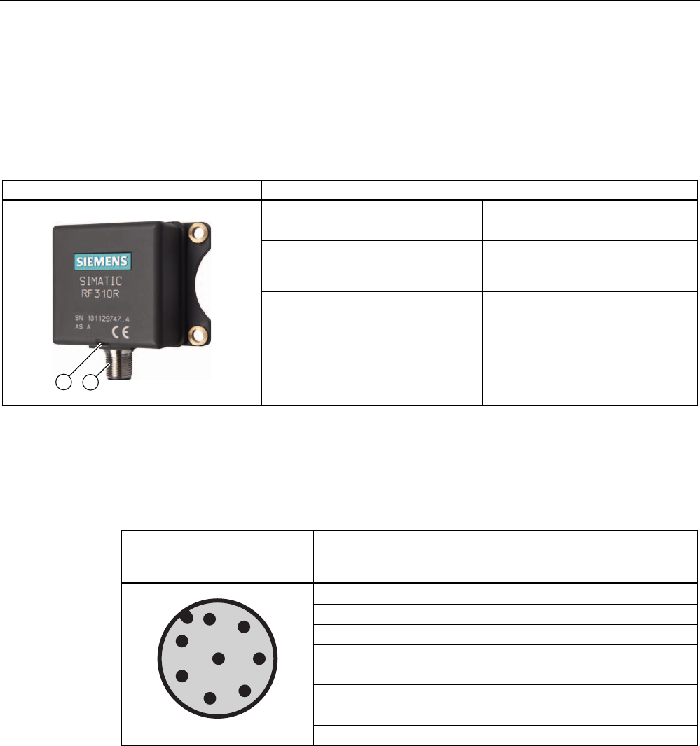
Reader RF310R Features
Structure ① RS422 interface
② Status display
Field of application Identification tasks on small
assembly lines in harsh industrial
environments
Read/write distance to transponder Max. 30 mm
Data transmission rate • Read: approx. 3100 byte/s
• Write: approx. 3100 byte/s
5.3.2 Pin assignment of RF310R RS422 interface
Pin Pin
Device end
8-pin M12
Assignment
1 + 24 V
2 - Transmit
3 0 V
4 + Transmit
5 + Receive
6 - Receive
7 Free
8 Earth (shield)
Readers
5.3 RF310R with RS422 interface
SIMATIC RF300
94 System Manual, 09/2007, J31069 D0166-U001-A5-7618
5.3.3 Display elements of the RF310R reader with RS422 interface
Color Meaning
Flashing Operating voltage present, reader not initialized or antenna switched off Green
Permanentl
y on
Operating voltage present, reader initialized and antenna switched on
Yellow1) Transponder present
Flashing red Error has occurred, the type of flashing corresponds to the error code in the
table in Section "Error codes". The optical error display is only reset if the
corresponding reset parameter ("option_1", see FC45 / FB45 documentation,
Section "Input parameters") is set.
1) In the operating state "Without presence", the lighting duration may be very short.
5.3.4 Ensuring reliable data exchange
The "center point" of the transponder must be situated within the transmission window.
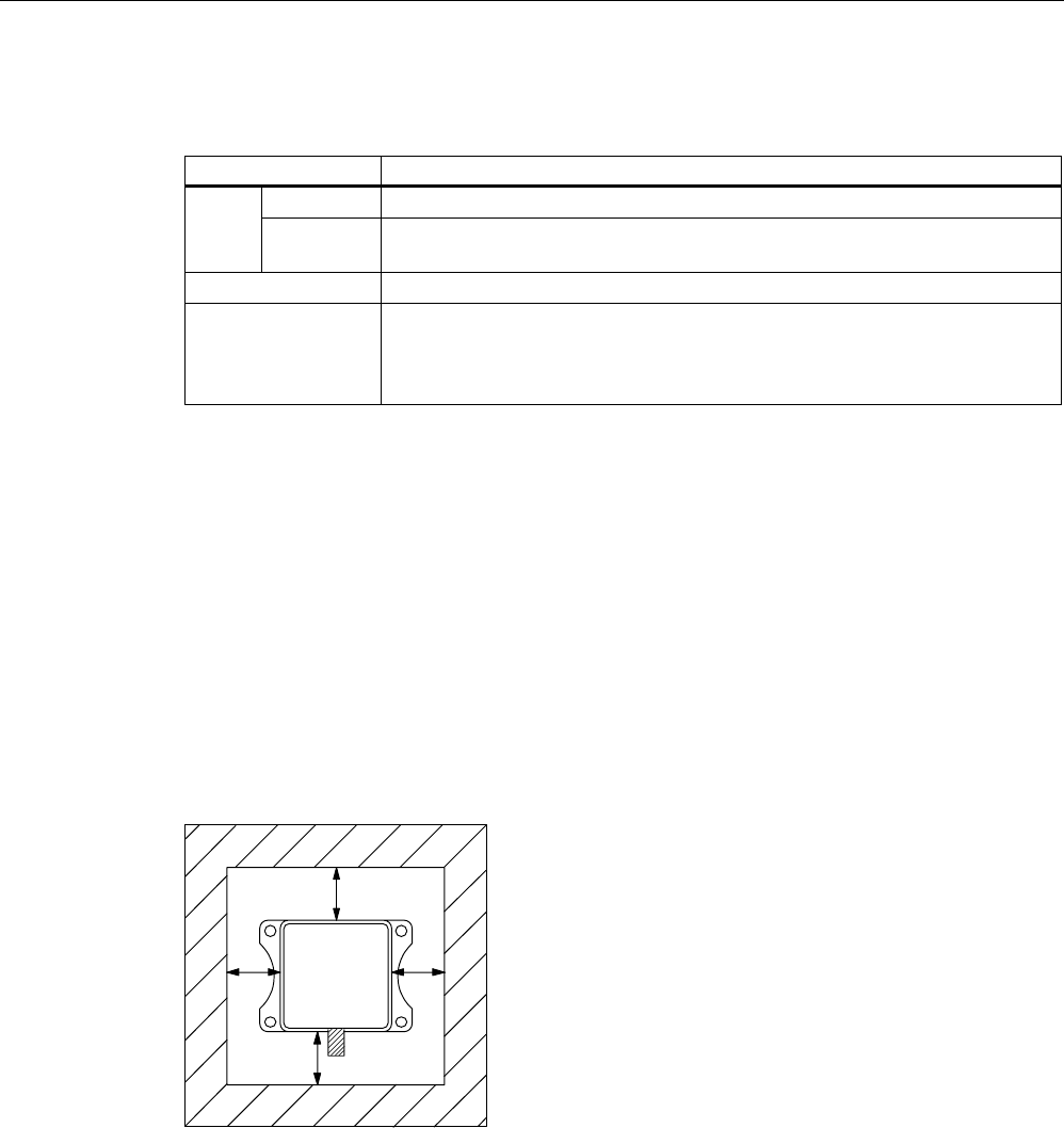
5.3.5 Metal-free area
The RF310R can be flush-mounted in metal. Please allow for a possible reduction in the field
data values.
D
D
DD
6,0$7,&
5)5
Figure 5-4 Metal-free area for RF310R
To avoid any impact on the field data, the distance a should be ≥ 20 mm.
Readers
5.3 RF310R with RS422 interface
SIMATIC RF300
System Manual, 09/2007, J31069 D0166-U001-A5-7618 95
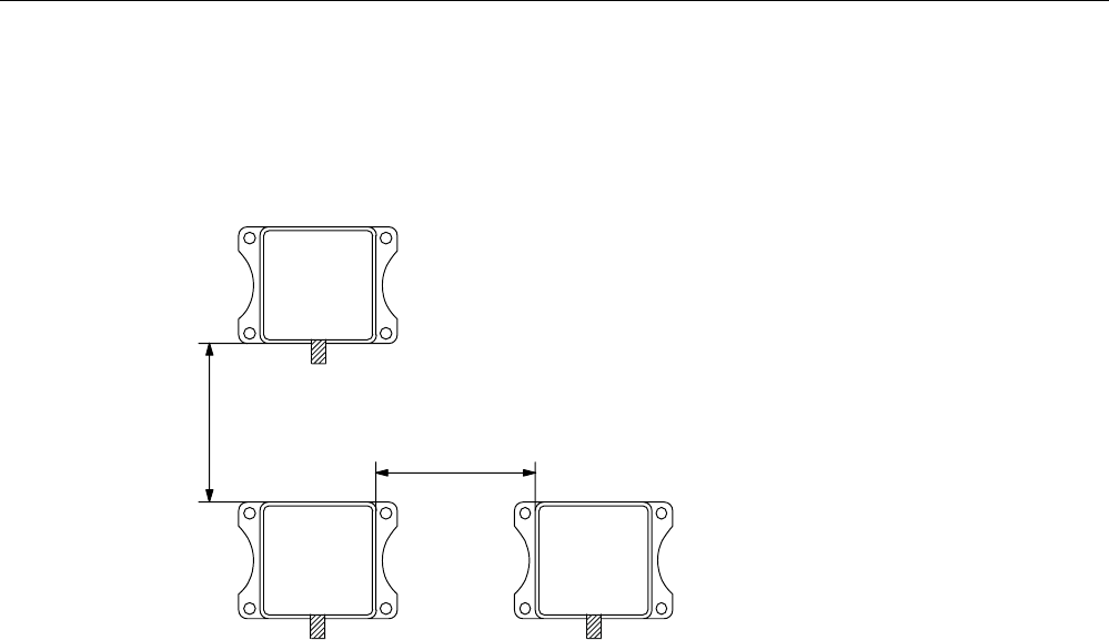
5.3.6 Minimum distance between RF310R readers
ุPP
0LQLPXPGLVWDQFHEHWZHHQ5)5DQG5)5
'
'
'
5)5
6,0$7,&
5)5
6,0$7,&
5)5
6,0$7,&
Figure 5-5 Minimum distance between RF310R readers

Readers
5.3 RF310R with RS422 interface
SIMATIC RF300
96 System Manual, 09/2007, J31069 D0166-U001-A5-7618
5.3.7 Technical specifications of the RF310R reader with RS422 interface
Table 5-3 Technical specifications of the RF310R reader with RS422 interface
Inductive interface to the transponder
Transmission frequency for power/data
13.56 MHz
Antenna Integrated
Interface to communication module RS422 (3964R protocol)
Baud rate 19200 baud, 57600 baud, 115200 baud
Cable length between reader and communication
module
Data cable length max. 1000 m
(shielded cable)
Read/write distances of reader See RF310R field data
Minimum distance between two RF310R readers ≥ 400 mm
Maximum data transfer rate from reader to
transponder (Tag)
Reading
Writing
Approx. 3100 byte/s
Approx. 3100 byte/s
Functions Initialize/read/write transponder
Scan status and diagnostics information
Switch antenna on/off
Repeat command
Scan transponder serial numbers
Power supply 24 V DC
Display elements 2-color LED (operating voltage,
presence, error)
Plug connector M12 (8-pin)
Enclosure
Dimensions (in mm)
Color
Material
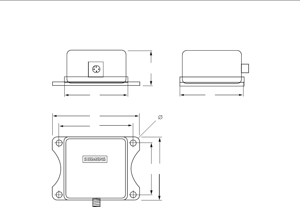
55 x 75 x 30 (without M12 device connector)
Anthracite
Plastic PA 12
Fixing 4 x M5 screws
Ambient temperature
during operations
during transport and storage
-25 °C to +70 °C
-40 °C to +85 °C
Degree of protection to EN 60529
Shock to EN 60 721-3-7 Class 7 M2
Vibration to EN 60 721-3-7 Class 7 M2
IP67
50 g
20 g
Weight Approx. 200 g
MTBF (Mean Time Between Failures) in years 169,9
Approvals Radio to R&TTE guidelines EN 300 330,
EN 301489, CE, FCC, UL/CSA
Current consumption typ. 40 mA

Readers
5.3 RF310R with RS422 interface
SIMATIC RF300
System Manual, 09/2007, J31069 D0166-U001-A5-7618 97
5.3.8 FCC information
Siemens SIMATIC RF310R with RS422 interface
FCC ID: NXW-RF310R
This device complies with Part 15 of the FCC rules. Operation is subject to the following two
conditions:
(1) This device may not cause harmful interference.
(2) This device must accept any interference received, including interference that may cause
undesired operation.
Caution
Any changes or modifications not expressly approved by the party responsible for
compliance could void the user's authority to operate the equipment.
5.3.9 Ordering data for RF310R with RS422 interface
RF310R Order No.
With RS422 interface (3964R)
IP 67, -25 °C to +70 °C, 55 x 75 x 30 (L x W x H in mm), with integrated
antenna, max. limit distance 30 mm (depending on transponder)
6GT2801-1AA10
Readers
5.3 RF310R with RS422 interface
SIMATIC RF300
98 System Manual, 09/2007, J31069 D0166-U001-A5-7618
5.3.10 Dimension drawing
6,0$7,&
5)5
Figure 5-6 Dimension drawing for RF310R
Dimensions in mm
Readers
5.4 RF340R
SIMATIC RF300
System Manual, 09/2007, J31069 D0166-U001-A5-7618 99
5.4 RF340R
5.4.1 Features
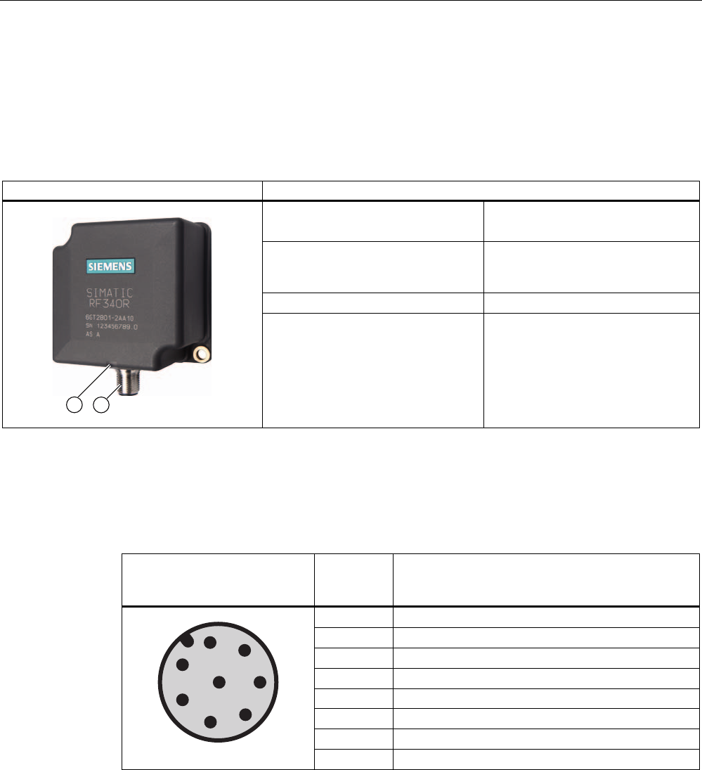
Reader RF340R Features
Design ① RS422 interface
② Status display
Area of application Identification tasks on assembly
lines in harsh industrial
environments
Read/write distance to transponder max. 60 mm
Data transmission rate • Read: approx. 3,100 byte/s
• Write: approx. 3,100 byte/s
5.4.2 Pin assignment of RF340R RS422 interface
Pin Pin
Device end
8-pin M12
Assignment
1 + 24 V
2 - Transmit
3 0 V
4 + Transmit
5 + Receive
6 - Receive
7 Free
8 Earth (shield)
Readers
5.4 RF340R
SIMATIC RF300
100 System Manual, 09/2007, J31069 D0166-U001-A5-7618
5.4.3 Display elements of the RF340R reader
Color Meaning
Flashing Operating voltage present, reader not initialized or antenna switched off Green
Permanentl
y on
Operating voltage present, reader initialized and antenna switched on
Yellow1) Transponder present
Flashing red Error has occurred, the type of flashing corresponds to the error code in the
table in Section "Error codes". The optical error display is only reset if the
corresponding reset parameter ("option_1", see FC45 / FB45 documentation,
Section "Input parameters") is set.
1) In the operating state "Without presence", the lighting duration may be very short.
5.4.4 Ensuring reliable data exchange
The "center point" of the transponder must be situated within the transmission window.
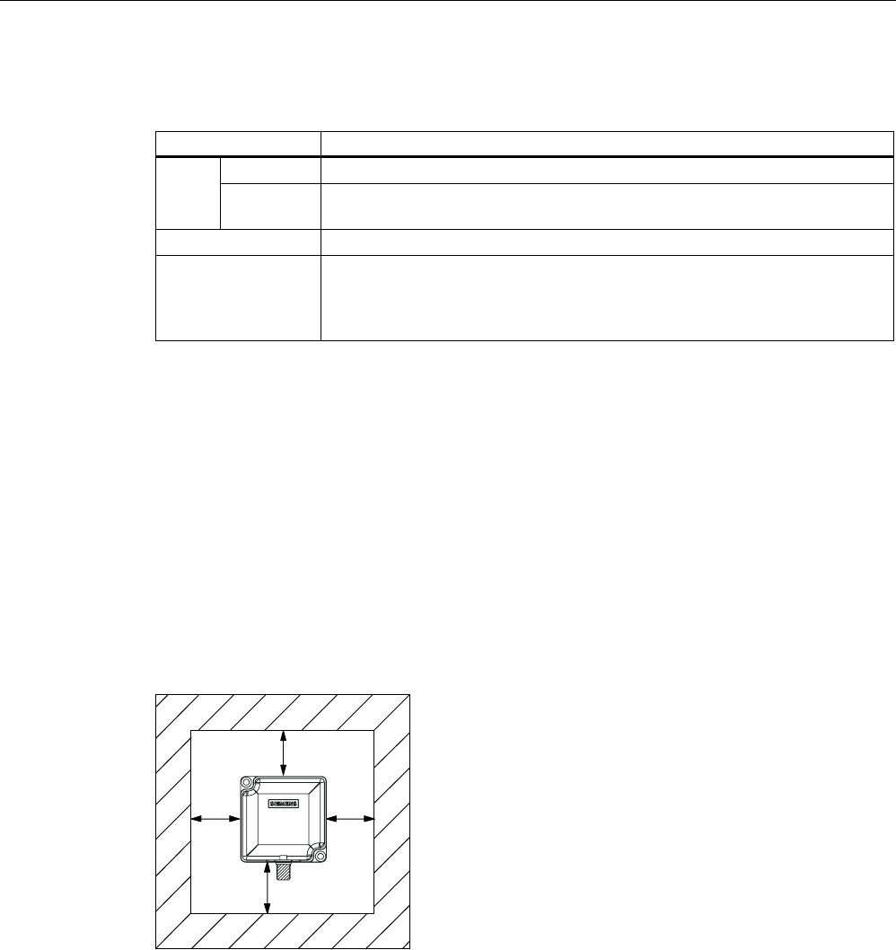
5.4.5 Metal-free area
The RF340R can be flush-mounted in metal. Please allow for a possible reduction in the field
data values.
6,0$7,&
D
D
DD
5)5
Figure 5-7 Metal-free area for RF340R
To avoid any impact on the field data, the distance a should be ≥ 20 mm.
Readers
5.4 RF340R
SIMATIC RF300
System Manual, 09/2007, J31069 D0166-U001-A5-7618 101
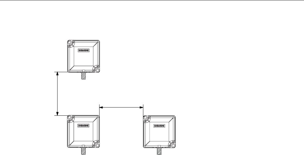
5.4.6 Minimum distance between RF340R readers
ุPP
0LQLPXPGLVWDQFHIURP5)5WR5)5
'
'
'
5)5
5)5 5)5
Figure 5-8 Minimum distance between RF340R readers

Readers
5.4 RF340R
SIMATIC RF300
102 System Manual, 09/2007, J31069 D0166-U001-A5-7618
5.4.7 Technical data of the RF340R reader
Table 5-4 Technical specifications of the RF340R reader
Inductive interface to the transponder
Transmission frequency for power/data
13.56 MHz
Antenna Integrated
Interface to communication module RS422 (3964R protocol)
Baud rate 19200 baud, 57600 baud, 115200 baud
Cable length between reader and communication
module
Data cable length max. 1000 m
(shielded cable)
Read/write distances of reader See RF340R field data
Minimum distance between two RF340R readers ≥ 500 mm
Maximum data transfer rate
reader - transponder (tag)
Reading
Writing
Approx. 3100 byte/s
Approx. 3100 byte/s
Functions Initialize/read/write transponder
Scan status and diagnostics information
Switch antenna on/off
Repeat command
Scan transponder serial numbers
Power supply 24 V DC
Display elements 2-color LED
(operating voltage, presence, error)
Plug connector M12 (8-pin)
Enclosure
Dimensions (in mm)
Color
Material
75 x 75 x 40 (without M12 device connector)
Anthracite
Plastic PA 12
Fixing 2 x M5 screws
Ambient temperature
during operations
during transport and storage
-25 °C to +70 °C
-40 °C to +85 °C
Degree of protection to EN 60529
Shock to EN 60 721-3-7 Class 7 M2
Vibration to EN 60 721-3-7 Class 7 M2
IP 67
50 g
20 g
Weight Approx. 250 g
MTBF (Mean Time Between Failures) in years 140,3
Approvals Radio to R&TTE guidelines EN 300 330,
EN 301489, CE, FCC, UL/CSA
Current consumption typ. 100 mA

Readers
5.4 RF340R
SIMATIC RF300
System Manual, 09/2007, J31069 D0166-U001-A5-7618 103
5.4.8 FCC information
Siemens SIMATIC RF340R
FCC ID: NXW-RF340R
This device complies with Part 15 of the FCC rules. Operation is subject to the following two
conditions:
(1) This device may not cause harmful interference.
(2) This device must accept any interference received, including interference that may cause
undesired operation.
Caution
Any changes or modifications not expressly approved by the party responsible for
compliance could void the user's authority to operate the equipment.
5.4.9 Ordering data for RF340R
Product description Order No.
Reader RF340R
With RS422 interface (3964R)
IP67;
-25 °C to +70 C, dimensions 75 x 91 x 41 (L x W x H in mm);
with integrated antenna;
max. limit distance 65 mm (depending on transponder)
6GT2801-2AA10
Readers
5.4 RF340R
SIMATIC RF300
104 System Manual, 09/2007, J31069 D0166-U001-A5-7618
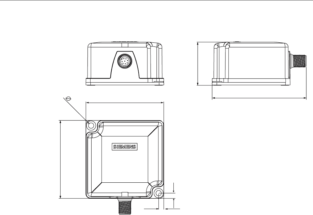
5.4.10 Dimension drawing
6,0$7,&
5)5
Figure 5-9 Dimension drawing for RF340R
Dimensions in mm
Readers
5.5 RF350R
SIMATIC RF300
System Manual, 09/2007, J31069 D0166-U001-A5-7618 105
5.5 RF350R
5.5.1 Features
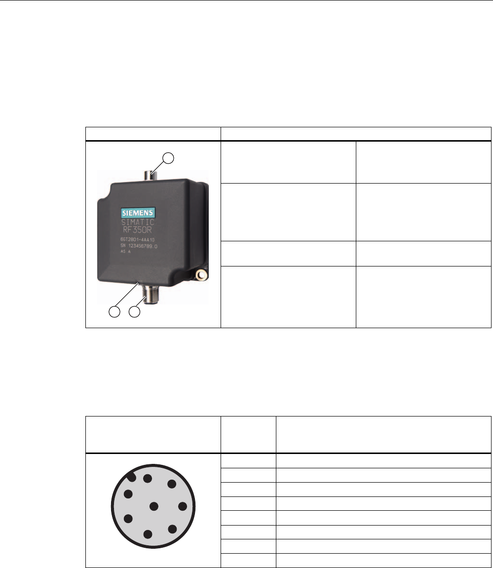
Reader RF350R Features
Design ① Antenna connection
② RS422 interface
③ Status display
Area of application Identification tasks in assembly
lines in harsh industrial
environments; for external
antennas
(ANT 1, ANT 18, ANT 30)
Read/write distance to
transponder
Max. 60 mm
Data transmission rate • Read: approx. 3,100 byte/s
• Write: approx. 3,100 byte/s
5.5.2 Pin assignment of RF350R RS422 interface
Pin Pin
Device end
8-pin M12
Assignment
1 + 24 V
2 - Transmit
3 0 V
4 + Transmit
5 + Receive
6 - Receive
7 Free
8 Earth (shield)

Readers
5.5 RF350R
SIMATIC RF300
106 System Manual, 09/2007, J31069 D0166-U001-A5-7618
5.5.3 Display elements of the RF350R reader
Color Meaning
Flashing Operating voltage present, reader not initialized or antenna switched off Green
Permanentl
y on
Operating voltage present, reader initialized and antenna switched on
Yellow1) Transponder present
Flashing red Error has occurred, the type of flashing corresponds to the error code in the
table in Section "Error codes". The optical error display is only reset if the
corresponding reset parameter ("option_1", see FC45 / FB45 documentation,
Section "Input parameters") is set.
1) In the operating state "Without presence", the lighting duration may be very short.
5.5.4 Ensuring reliable data exchange
The "center point" of the transponder must be situated within the transmission window.
5.5.5 Metal-free area
The RF350R reader does not have an internal antenna. Operation is not affected by
mounting on metal or flush-mounting in metal. For information about the metal-free area
required by the external antennas, refer to the corresponding section of the chapter
Antennas (Page 110).

Readers
5.5 RF350R
SIMATIC RF300
System Manual, 09/2007, J31069 D0166-U001-A5-7618 107
5.5.6 Technical data of the RF350R reader
Table 5-5 Technical specifications of the RF350R reader
Inductive interface to the transponder
Transmission frequency for power/data
13.56 MHz
Antenna External, plug-in MOBY E antennas ANT 1,
ANT 18 or ANT 30
Interface to communication module RS422 (3964R protocol)
Baud rate 19200 baud, 57600 baud, 115 baud
Cable length between reader and communication
module
Data cable length max. 1000 m
(shielded cable)
Read/write distances of reader See field data
Minimum distance between two antennas See field data
Maximum data transfer rate
reader - transponder (tag)
Reading
Writing
Approx. 3100 byte/s
Approx. 3100 byte/s
Functions Initialize/read/write transponder
Scan status and diagnostics information
Switch antenna on/off
Repeat command
Scan transponder serial numbers
Power supply 24 V DC
Display elements 2-color LED
(operating voltage, presence, error)
Plug connector M12 (8-pin); M8 (4-pin) for antenna
Enclosure
Dimensions (in mm)
Color
Material
75 x 75 x 40 (without M12 device connector)
Anthracite
Plastic PA 12
Fixing 2 x M5 screws
Ambient temperature
during operations
during transport and storage
-25 °C to +70 °C
-40 °C to +85 °C
Degree of protection to EN 60529
Shock to EN 60 721-3-7 Class 7 M2
Vibration to EN 60 721-3-7 Class 7 M2
IP65
50 g
20 g
Weight Approx. 400 g
MTBF (Mean Time Between Failures) in years 109
Approvals Radio to R&TTE guidelines EN 300 330,
EN 301489, CE, FCC, UL/CSA
Current consumption typ. 100 mA

Readers
5.5 RF350R
SIMATIC RF300
108 System Manual, 09/2007, J31069 D0166-U001-A5-7618
5.5.7 FCC information
Siemens SIMATIC RF350R
FCC ID: NXW-RF350R
This device complies with Part 15 of the FCC rules. Operation is subject to the following two
conditions:
(1) This device may not cause harmful interference.
(2) This device must accept any interference received, including interference that may cause
undesired operation.
Caution
Any changes or modifications not expressly approved by the party responsible for
compliance could void the user's authority to operate the equipment.
5.5.8 Ordering data for RF350R
Product description Order No.
Reader RF350R
With RS422 interface (3964R)
IP 65;
-25 °C to +70 °C, dimensions 75 x 96 x 41 (L x W x H in mm);
for plug-in antennas from the MOBY E product range;
max. limit distance 65 mm (depending on transponder)
6GT2801-4AA10
Readers
5.5 RF350R
SIMATIC RF300
System Manual, 09/2007, J31069 D0166-U001-A5-7618 109
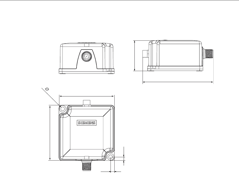
5.5.9 Dimension drawing
6,0$7,&
5)5
Figure 5-10 RF350R dimension drawing
Dimensions in mm
Readers
5.5 RF350R
SIMATIC RF300
110 System Manual, 09/2007, J31069 D0166-U001-A5-7618
5.5.10 Antennas
5.5.10.1 Features
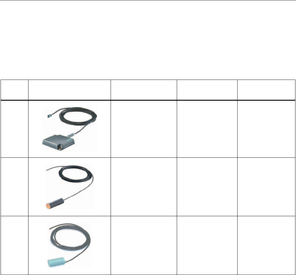
You can use the following plug-in antennas from the MOBY E product spectrum for the
RF350R reader:
Antenna Product photo Limit distance Sg
in mm 1)
Dimensions
(L x B x H)
in mm
Suitable for dynamic
operation
MOBY E
ANT 1
to 60 75 x 75 x 20 Yes
MOBY E
ANT 18
to 13 Ø M18 x 50 no
MOBY E
ANT 30
to 22 Ø M30 x 58 no
1) depending on the transponder used
ANT 1
The ANT 1 is an antenna in the mid performance range and can be used to the customer's
advantage in production and assembly lines due to its manageable housing shape. The
antenna dimensions make it possible to read/write large quantities of data dynamically
from/to the tag during operation. The antenna cable can be connected at the reader end.
ANT 18
The ANT 18 is designed for use in small assembly lines. Due to its small, compact
construction, the antenna can be easily positioned for any application using two plastic nuts
(included in the package). The antenna cable can be connected at the reader end. With the
RF320T and RF340T tags, communication with the data storage unit is only possible in static
mode.

Readers
5.5 RF350R
SIMATIC RF300
System Manual, 09/2007, J31069 D0166-U001-A5-7618 111
ANT 30
The ANT 30 is designed for use in small assembly lines. In comparison to ANT 18, the
maximum write/read distance is approximately 60 % larger. Due to its compact construction,
the antenna can be easily positioned for any application using two plastic nuts (included in
the package). The antenna cable can be connected at the reader end. With the RF320T,
RF340T and RF350T tags, communication with the data storage unit is only possible in static
mode.
Readers
5.5 RF350R
SIMATIC RF300
112 System Manual, 09/2007, J31069 D0166-U001-A5-7618
5.5.10.2 Ensuring reliable data exchange
The "center point" of the transponder must be situated within the transmission window.
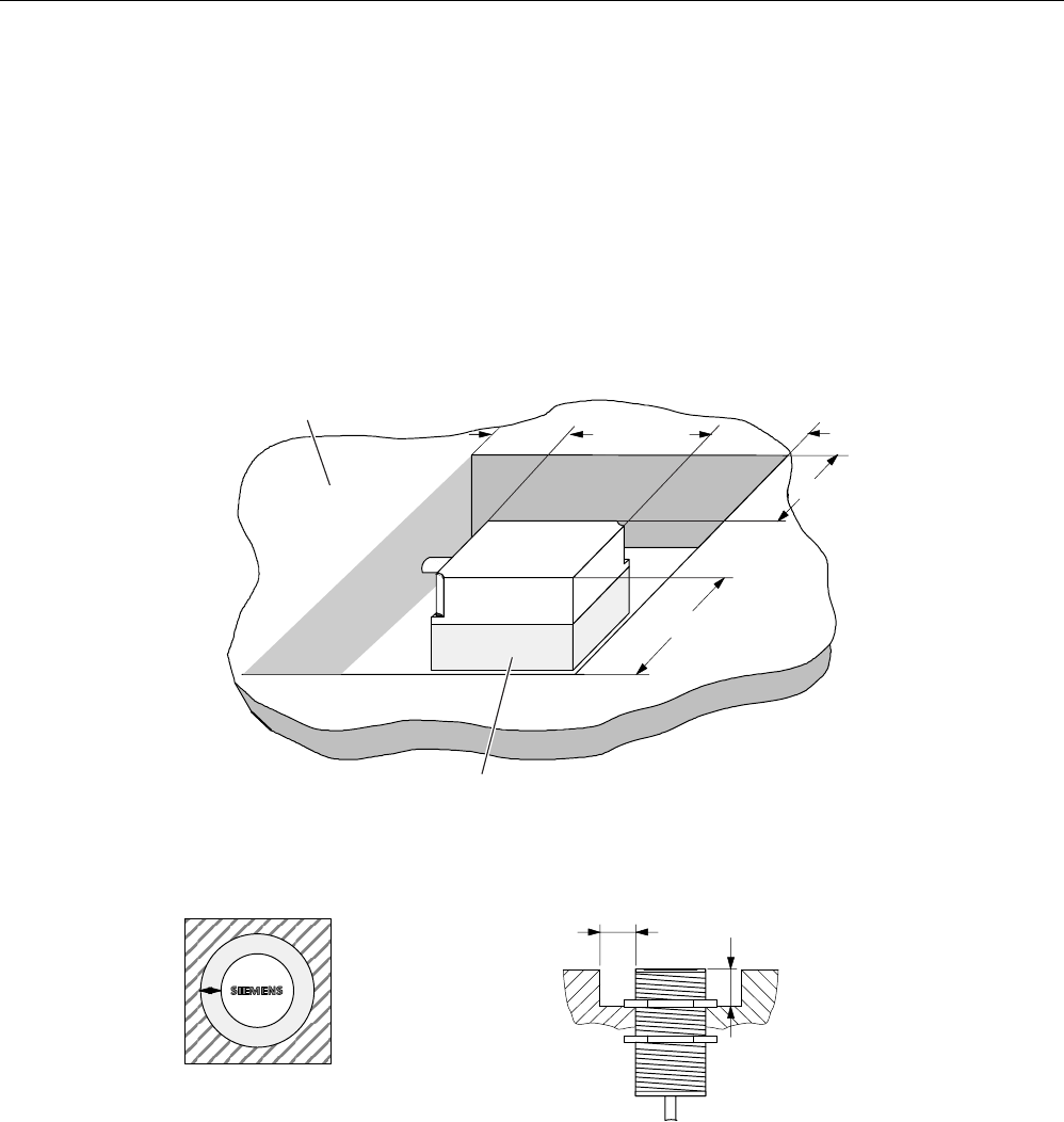
5.5.10.3 Metal-free area
The antennas ANT1, ANT18 and ANT30 can be flush-mounted on metal. Please allow for a
possible reduction in the field data values.
0HWDOIUHHDUHDIRUIOXVKPRXQWLQJ
QRWDPHWDOOLFEDVH
0HWDO
a = 40 mm
h > 20 mm
a
a
a
a
h > 20 mm
Figure 5-11 Metal-free area for ANT 1
1RWH
,IWKHPHWDOIUHHDUHDLVQRW
REVHUYHGWKHOLPLWDQGRSHUDWLQJ
GLVWDQFHVDUHUHGXFHG
0HWDOIUHHDUHDIRU
IOXVKPRXQWLQJ
D
E
D PP
E PP
$17
02%<(
$17
D
Figure 5-12 Metal-free area for ANT 18
Readers
5.5 RF350R
SIMATIC RF300
System Manual, 09/2007, J31069 D0166-U001-A5-7618 113
D
E
D PP
E PP
D02%<(
$17
3ODQYLHZ
6LGHYLHZ
Figure 5-13 Metal-free area for ANT 30
Readers
5.5 RF350R
SIMATIC RF300
114 System Manual, 09/2007, J31069 D0166-U001-A5-7618
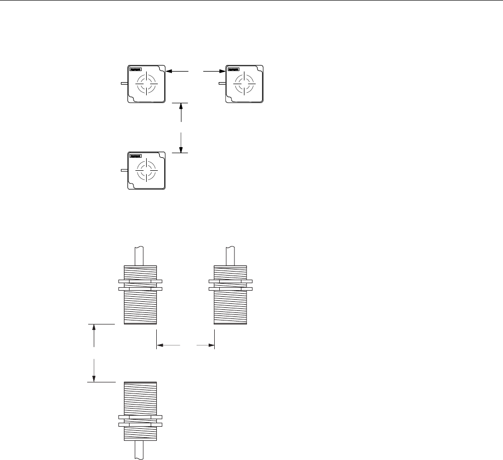
5.5.10.4 Minimum distance between antennas
7KHUHDGHUHOHFWURQLFVFDQEH
PRXQWHGGLUHFWO\DORQJVLGHHDFKRWKHU
$
17
E
'PP
D!
B
$17
$17
'PP
!
B
'
D
E
'
Figure 5-14 Minimum distance for ANT 1
'
D
ุPP
'
D
'
D
Figure 5-15 Minimum distance for ANT 18
Readers
5.5 RF350R
SIMATIC RF300
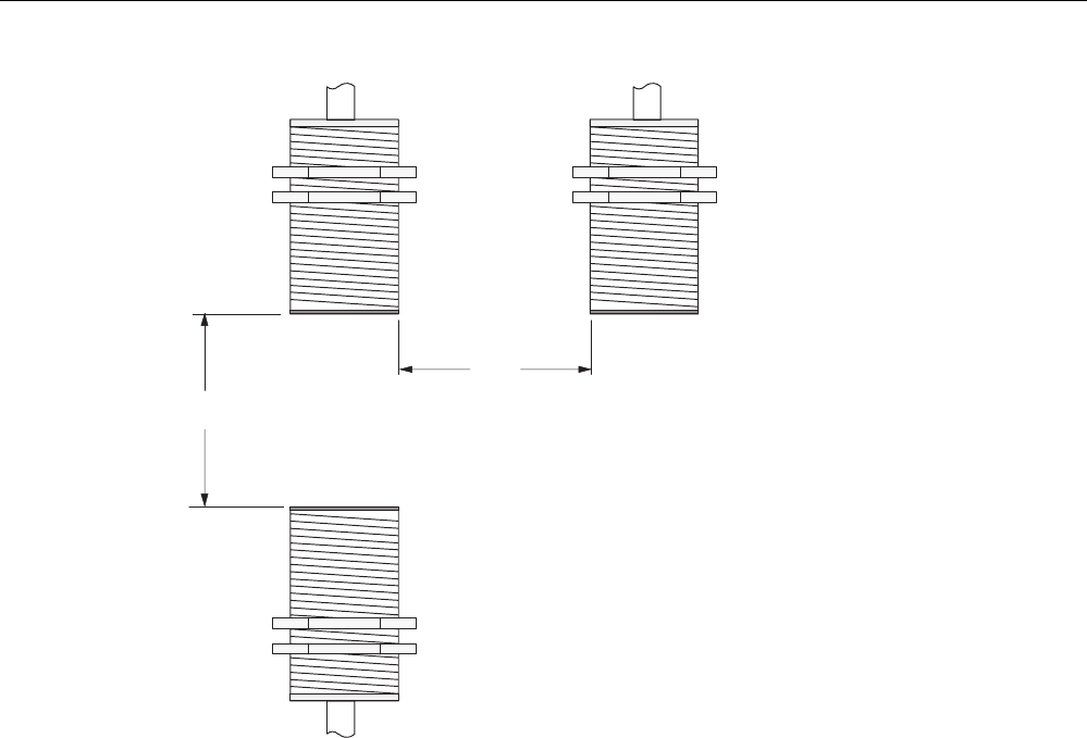
System Manual, 09/2007, J31069 D0166-U001-A5-7618 115
'
D
!PP
'
D
'
D
Figure 5-16 Minimum distance for ANT 30

Readers
5.5 RF350R
SIMATIC RF300
116 System Manual, 09/2007, J31069 D0166-U001-A5-7618
5.5.10.5 Technical data for antennas
Table 5-6 Technical data for antennas ANT1, ANT18 and ANT30
Antenna ANT1 ANT18 ANT30
Read/write distance
antenna to transponder (Sg) max
100 mm 15 mm 24 mm
Enclosure dimensions in mm 75 x 75 x 20
(L x W x H)
M18 x 1.0 x 55
(Ø x thread x L)
M30 x 1.5 x 58
(Ø x thread x L)
Color Anthracite Pale turquoise
Material Plastic PA 12 Plastic Krastin
Plug connection 4-pin (pins on antenna side)
Antenna cable lengths 3 m
Degree of protection according to
EN 60529
IP 67 IP 67 (at the front)
Shock-resistant acc. to
EN 60721-3-7, Class 7M2
Vibration-resistant to
EN 60721-3-7, Class 7M2
50 g 1)
20 g ( 3 to 500 Hz) 1)
Attachment of the antenna 2 x M5 screws 2 plastic nuts M18 x
1.0
2 plastic nuts M30 x
1.5
Ambient temperature
• During operation
• Storage and transport
• -25 °C to +70 °C
• -40 °C to +85 °C
MTBF (at +40 °C) 2,5 x 10⁵ hours
Approx. weight 80 g 120 g 150 g
1) Warning: The values for shock and vibration are maximum values and must not be applied
continuously.
5.5.10.6 Ordering data for antennas
Product description Order No.
MOBY E, ANT 1 6GT2398-1CB00
MOBY E, ANT 18 6GT2398-1CA00
MOBY E, ANT 30 6GT2398-1CD00
Readers
5.5 RF350R
SIMATIC RF300
System Manual, 09/2007, J31069 D0166-U001-A5-7618 117
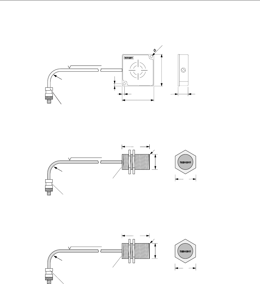
5.5.10.7 Dimension drawings for antennas
&DEOHOHQJWKP
0LQLPXPEHQGLQJ
UDGLXV
$17FDQEHFRQQHFWHG
DWUHDGHUHQG
20 mm
Figure 5-17 Dimension drawing for ANT 1
Dimensions in mm
&DEOHOHQJWKP
0LQLPXPEHQGLQJ
UDGLXV
$17FDQEHFRQQHFWHG
DWUHDGHUHQG
$QWHQQDKHDG
6LGHYLHZRI
DQWHQQDKHDG
$QWHQQDHQG
)LQHWKUHDGSLWFK
PP
0
02%<(
$17
Figure 5-18 Dimension drawing for ANT 18
Dimensions in mm
&DEOHOHQJWKP
0LQLPXPEHQGLQJ
UDGLXV
$17FDQEHFRQQHFWHG
DWUHDGHUHQG
$QWHQQDKHDG
6LGHYLHZRI
DQWHQQDKHDG
$QWHQQDHQG
)LQHWKUHDGSLWFK
PP
0
$17
02%<(
Figure 5-19 Dimension drawing for ANT 30
Dimensions in mm
Readers
5.6 RF380R
SIMATIC RF300
118 System Manual, 09/2007, J31069 D0166-U001-A5-7618
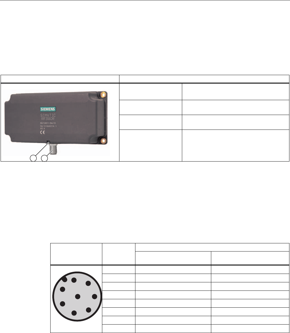
5.6 RF380R
5.6.1 Features
Reader RF350R Features
Structure ① RS232 or RS422 interface
② Status display
Field of application Identification tasks on assembly lines in
harsh industrial environments
Read/write distance to
transponder
Max. 150 mm
Data transmission rate • Read: approx. 3,100 byte/s
• Write: approx. 3,100 byte/s
5.6.2 Pin assignment of RF380R RS232/RS422 interface
You can connect the RF380R reader to a higher-level system via the internal RS422
interface or via the RS232 interface. After connection, the interface module automatically
detects which interface has been used.
Note correct assignment of the pins here:
Assignment Pin Pin
Device end
8-pin M12 RS232 RS422
1 + 24 V + 24 V
2 RXD - Transmit
3 0 V 0 V
4 TXD + Transmit
5 NC + Receive
6 NC - Receive
7 not used not used
8 Earth (shield) Earth (shield)
Readers
5.6 RF380R
SIMATIC RF300
System Manual, 09/2007, J31069 D0166-U001-A5-7618 119
5.6.3 Display elements of the RF380R reader
Color Meaning
Flashing Operating voltage present, reader not initialized or antenna switched off Green
Permanentl
y on
Operating voltage present, reader initialized and antenna switched on
Yellow1) Transponder present
Flashing red Error has occurred, the type of flashing corresponds to the error code in the
table in Section "Error codes". The optical error display is only reset if the
corresponding reset parameter ("option_1", see FC45 / FB45 documentation,
Section "Input parameters") is set.
1) In the operating state "Without presence", the lighting duration may be very short.
5.6.4 Ensuring reliable data exchange
The "center point" of the transponder must be situated within the transmission window.
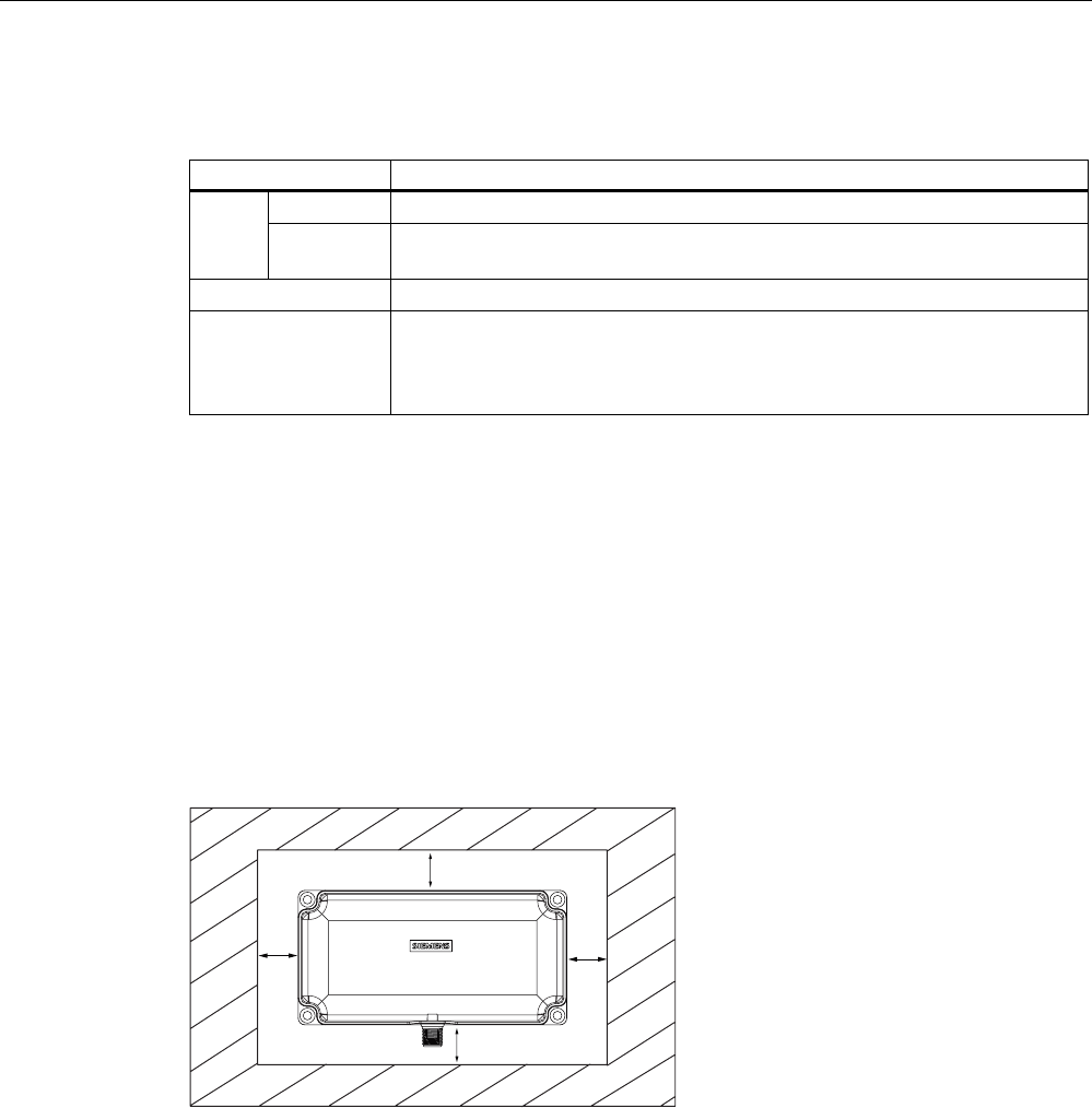
5.6.5 Metal-free area
The RF380R can be flush-mounted in metal. Please allow for a possible reduction in the field
data values.
D
D
D
D
6,0$7,&
5)5
Figure 5-20 Metal-free area for RF380R
To avoid any impact on the field data, the distance a should be ≥ 20 mm.
Readers
5.6 RF380R
SIMATIC RF300
120 System Manual, 09/2007, J31069 D0166-U001-A5-7618
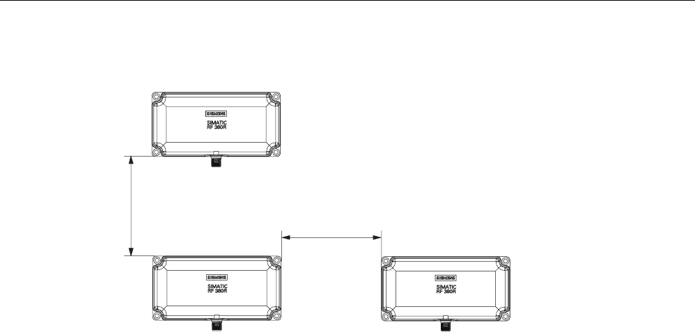
5.6.6 Minimum distance between RF380R readers
ุPP
0LQLPXPGLVWDQFHEHWZHHQ5)5DQG5)5
'
'
'
Figure 5-21 Minimum distance between RF380R readers

Readers
5.6 RF380R
SIMATIC RF300
System Manual, 09/2007, J31069 D0166-U001-A5-7618 121
5.6.7 Technical specifications of the RF380R reader
Table 5-7 Technical specifications of the RF380R reader
Inductive interface to the transponder
Transmission frequency for power/data
13.56 MHz
Antenna integrated
Interface to communication module RS232 or RS422 (3964R protocol)
Baud rate 19200 baud, 57600 baud, 115200 baud
Cable length between reader and communication
module
RS422 data cable length: max. 100 m
RS232 data cable length: Max. 30 m
Read/write distances of reader See RF380R field data
Minimum distance between two RF380R readers ≥ 500 mm
Maximum data transfer rate
reader - transponder (tag)
Reading
Writing
Approx. 3100 byte/s
Approx. 3100 byte/s
Functions Initialize/read/write transponder
Scan status and diagnostics information
Switch antenna on/off
Repeat command
Scan transponder serial numbers
Voltage supply 24 V DC
Indicators 2-color LED
(operating voltage, presence, error)
Connector M12 (8-pin)
Enclosure
Dimensions (in mm)
Color
Material
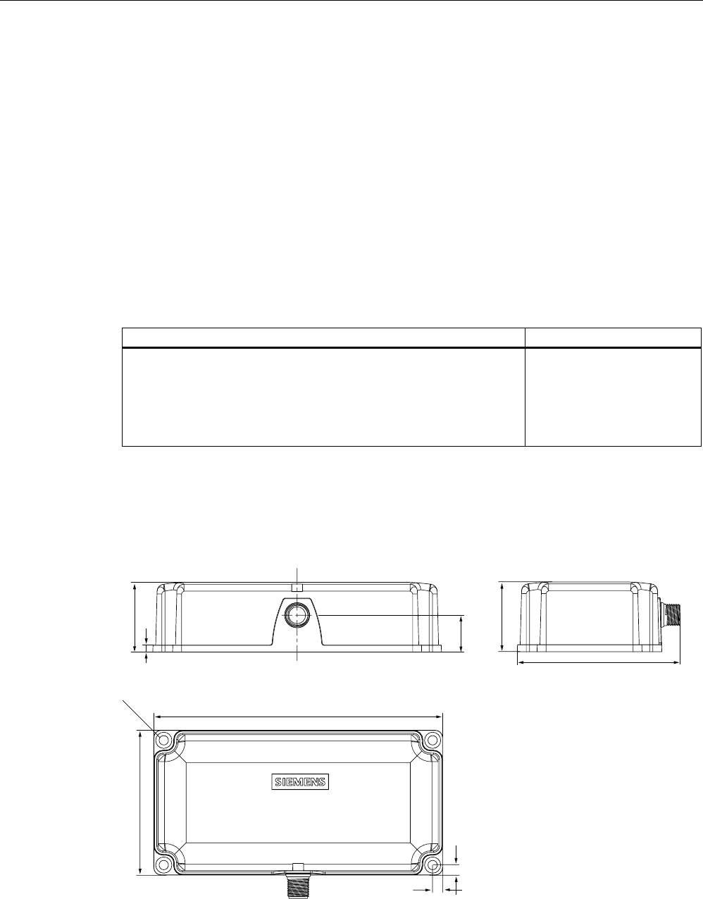
160 x 80 x 40 (without M12 plug connector)
Anthracite
Plastic PA 12
Fixing 4 x M5 screws
Ambient temperature
during operations
during transport and storage
-10 °C to +70 °C
-40 °C to +85 °C
Degree of protection to EN 60529
Shock to EN 60 721-3-7 Class 7 M2
Vibration to EN 60 721-3-7 Class 7 M2
IP67
50 g
20 g
Weight Approx. 400 g
MTBF (Mean Time Between Failures) in years 109 years
Approvals Radio to R&TTE guidelines EN 300 330,
EN 301489, CE
Current consumption typ. 160 mA
Readers
Reader RF380R
With RS422 interface (3964R)
IP67;
-10 °C to +60 C, dimensions 160 x 96 x 40 (L x W x H in mm);
with integrated antenna;
max. limit distance 150 mm (depending on transponder)
6GT2801-3AA10
5.6.10 Dimension drawing
6,0$7,&
5)5
Figure 5-22 Dimension drawing RF380R
Dimensions in mm
5.6 RF380R
SIMATIC RF300
122 System Manual, 09/2007, J31069 D0166-U001-A5-7618
5.6.8 FCC information
Siemens SIMATIC RF380R
FCC approval pending
Caution
Any changes or modifications not expressly approved by the party responsible for
compliance could void the user's authority to operate the equipment.
Product description Order No.
SIMATIC RF300
System Manual, 09/2007, J31069 D0166-U001-A5-7618 123
Transponders 6
6.1 Overview
Transponders consist predominantly of logic, FRAM and/or EEPROM.
If a transponder moves into the transmission window of the reader, the necessary power for
all of the circuit components is generated and monitored by the power supply unit. The
pulse-coded information is prepared in such a way that it can be processed further as pure
digital signals. The handling of data, including check routines, is performed by the logic,
which also manages the various memories.
Transponders
6.2 RF320T
SIMATIC RF300
124 System Manual, 09/2007, J31069 D0166-U001-A5-7618
6.2 RF320T
6.2.1 Features
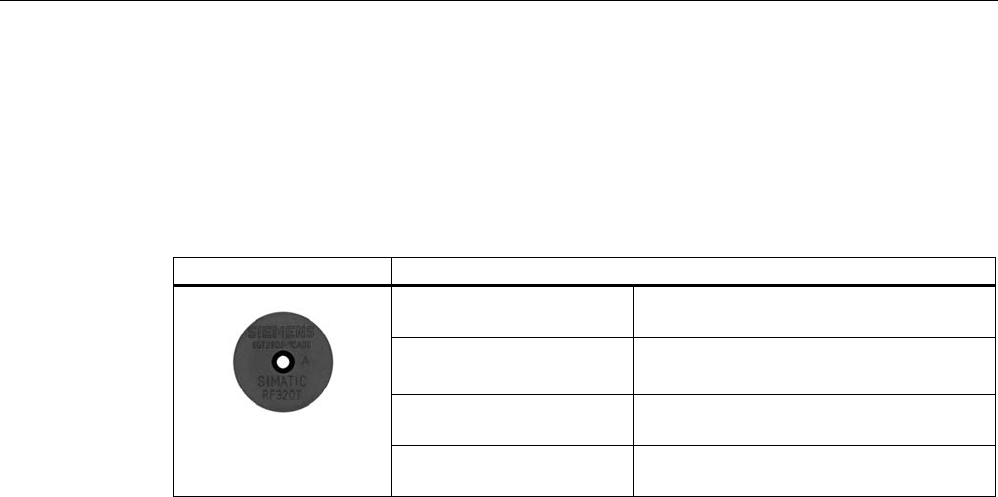
Transponder RF320T Features
Field of application Identification tasks on small assembly lines
in harsh industrial environments
Memory Read-only area (4 bytes UID)
User data area (20 bytes)
Read/write range See Section Field data for transponders,
readers and antennas (Page 37)
Mounting on metal Not possible Recommended distance from
metal ≥ 20 mm
Transponders
6.2 RF320T
SIMATIC RF300
System Manual, 09/2007, J31069 D0166-U001-A5-7618 125
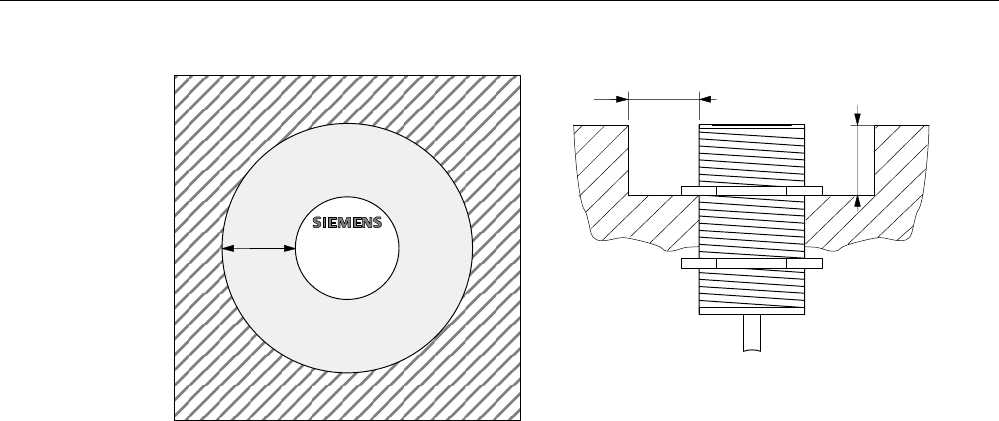
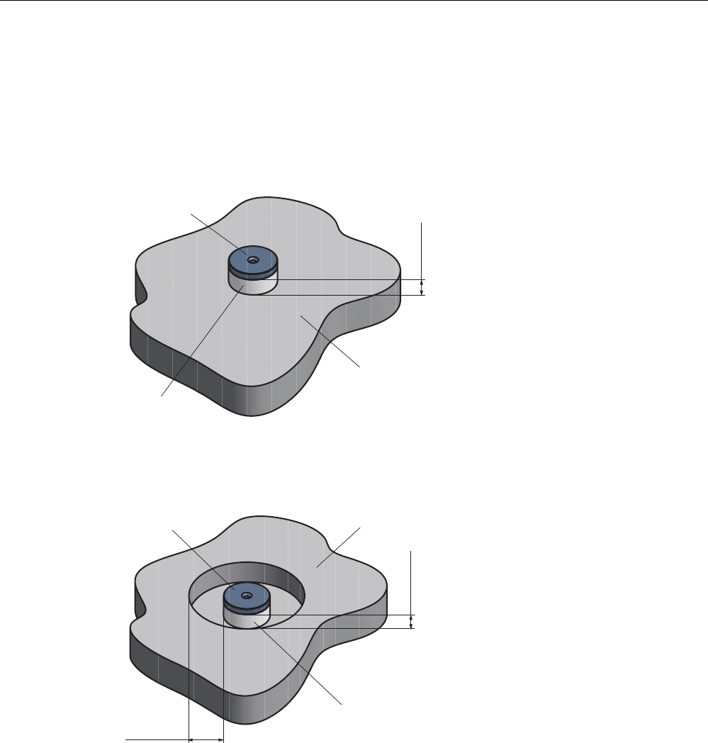
6.2.2 Metal-free area
Mounting of RF320T on metal
Direct mounting of the RF320T on metal is not allowed.
The following figures show the minimum distance between the RF320T and metal:
1RQPHWDO
0HWDO
K!PP
'DWDPHPRU\
Figure 6-1 Mounting of an RF320T on metal with spacer
Flush-mounting of RF320T in metal
D!PP
K!PP
'DWDPHPRU\ 0HWDO
1RQPHWDO
Figure 6-2 Flush-mounting of RF320T in metal with spacer
At lower values, the field data change significantly, resulting in a reduced range.

Transponders
6.2 RF320T
SIMATIC RF300
126 System Manual, 09/2007, J31069 D0166-U001-A5-7618
6.2.3 Technical data
Table 6-1 Technical data for RF320T
Memory size 20 bytes EEPROM (r/w), 4 bytes UID (ro)
Memory organization Byte-oriented access, write protection possible
in 4-byte blocks
MTBF (Mean Time Between Failures) in years 1871
Read cycles Unlimited
Write cycles, min. 50 000
at ≤ 40 °C, typical > 100 000
Data retention time > 10 years (at < +40 °C)
Write/read distance dependent on the reader used
(see field data)
Energy source Inductive power transmission
Shock/vibration-resistant to EN 60721-3-7, Class 7
M3
100 g/20 g
Torsion and bending load not permissible
Fixing Adhesive/M3 screws
Recommended spacing from metal > 20 mm
Degree of protection to EN 60529 • IP67/IPX9K
Housing
• Dimensions
• Color/material
Button
• Ø 27 mm x 4 mm
• Black/epoxy resin
Ambient temperature
• Operation
• Transport and storage
• -25 to +85 °C
• -40 to +125 °C
Weight Approx. 5 g
Note
All the technical data listed are typical data and are applicable for an ambient temperature of
between 0 C and +50°C and a metal-free environment.
6.2.4 Ordering data
Transponder RF320T Order number:
Transponder RF320T, button, 20 byte EEPROM,
IP 67, -25 °C to +85 °C, d = 27 mm x 4 mm
6GT2800-1CA00

Transponders
6.2 RF320T
SIMATIC RF300
System Manual, 09/2007, J31069 D0166-U001-A5-7618 127
6.2.5 Dimension drawing
Figure 6-3 RF320T dimension drawing
Dimensions in mm
Transponders
6.3 RF340T
SIMATIC RF300
128 System Manual, 09/2007, J31069 D0166-U001-A5-7618
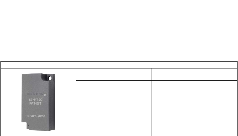
6.3 RF340T
6.3.1 Features
Transponder RF340T Features
Field of application Identification tasks on small assembly lines
in harsh industrial environments
Memory Read-only area (4 bytes UID)
Read/write memory (8 KB)
OTP 1) memory (20 bytes)
Read/write range See Section Field data for transponders,
readers and antennas (Page 37)
Mounting on metal Direct mounting on metal is possible.
1) OTP: One Time Programmable
Transponders
6.3 RF340T
SIMATIC RF300
System Manual, 09/2007, J31069 D0166-U001-A5-7618 129
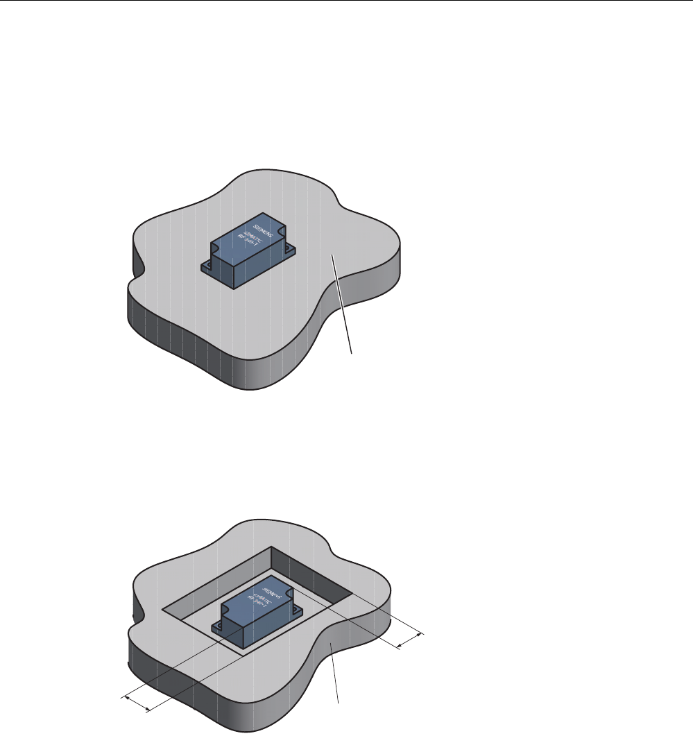
6.3.2 Metal-free area
Direct mounting of the RF340T on metal is permitted.
Mounting of RF340T on metal
0HWDO
Figure 6-4 Mounting of RF340T on metal
Flush-mounting of RF340T in metal:
D
D
0HWDO
Figure 6-5 Flush-mounting of RF340T in metal
The standard value for a is ≥ 20 mm. At lower values, the field data change significantly,
resulting in a reduction in the range.

Transponders
6.3 RF340T
SIMATIC RF300
130 System Manual, 09/2007, J31069 D0166-U001-A5-7618
6.3.3 Technical specifications
Table 6-2 Technical specifications for RF340T
Memory size 8 KB
Memory organization Blocks of 8 bits / 1 byte
Memory configuration
• Serial number (UID)
• Application memory
• OPT memory
• 4-byte (fixed code)
• 8189 bytes r/w
• 20-byte OTP 1) memory
Storage technology FRAM / EEPROM
MTBF (Mean Time Between Failures) in years 1201
Write cycles, at +40°C Virtually unlimited (>1010)
Read cycles Virtually unlimited (>1010)
Transmission rate
• Read
• Write
with RS422 reader:
Approx. 0.3 ms / byte
approx. 0.3 ms / byte
with IQ-Sense reader:
Approx. 20 ms / byte
approx. 25 ms / byte
Data retention > 10 years
Read/write distance dependent on the reader used (see field data)
Multitag capability max. 4 transponders
Recommended spacing from metal can be directly mounted on metal
Power supply Inductive, without battery
Degree of protection to EN 60529
Shock to EN 60721-3-7
Vibration to EN 60721-3-7
Torsion and bending load
IP68/IPX9K
50 g
20 g
Not permitted permanently
Housing dimensions
Color
Material
Fixing
48 x 25 x 15 mm (L x W x H)
Anthracite
PA12
2 screws (M3)
Ambient temperature
• During operation
• Storage and transport
-25°C to +85°C
-40°C to +85°C
Weight Approx. 25 g
1) OTP: (One Time Programmable)
6.3.4 Ordering data
Transponder RF340T Order No.
Transponder RF340T, 8 KB FRAM, IP 68, -25 °C
to +85 °C, 48 x 25 x 15 mm (L x W x H)
6GT2800-4BB00
Transponders
6.3 RF340T
SIMATIC RF300
System Manual, 09/2007, J31069 D0166-U001-A5-7618 131
6.3.5 Dimension drawing
6,(0(16
6,0$7,&
5)7
Figure 6-6 RF340T dimension drawing
Dimensions in mm
Transponders
6.4 RF350T
SIMATIC RF300
132 System Manual, 09/2007, J31069 D0166-U001-A5-7618
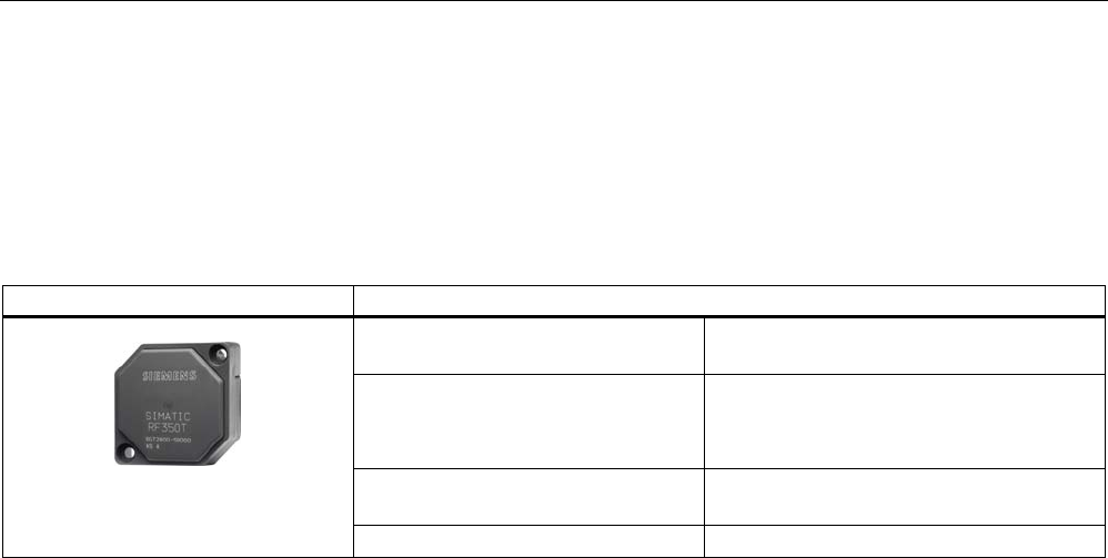
6.4 RF350T
6.4.1 Features
Transponder RF350T Features
Field of application Identification tasks on small assembly lines
in harsh industrial environments
Memory Read-only area (4 bytes UID)
Read/write memory (32 KB)
OTP 1) memory (20 bytes)
Read/write range See Section Field data for transponders,
readers and antennas (Page 37)
Mounting on metal Direct mounting on metal is possible.
1) OTP: One Time Programmable
Transponders
6.4 RF350T
SIMATIC RF300
System Manual, 09/2007, J31069 D0166-U001-A5-7618 133
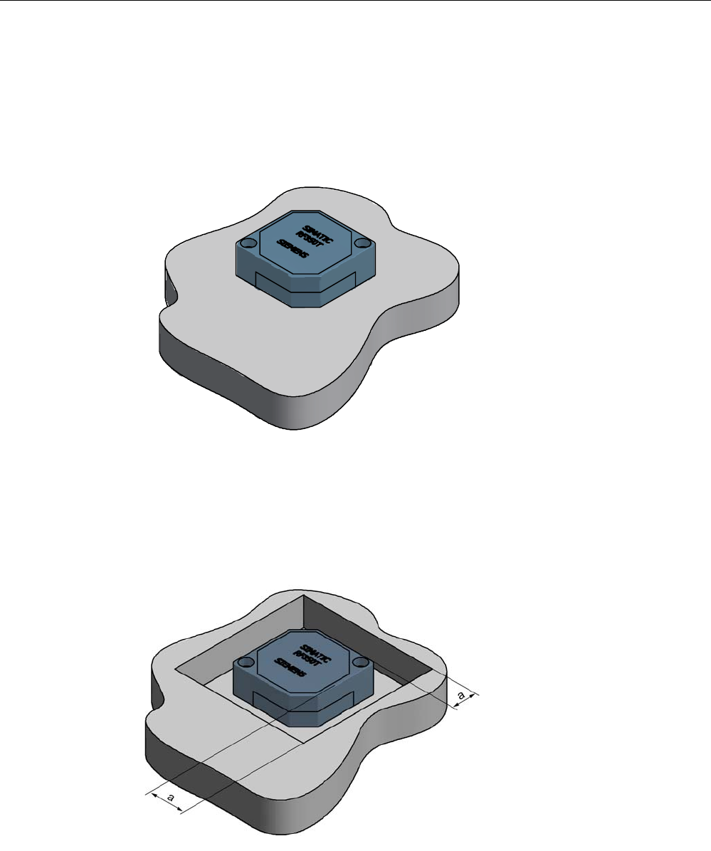
6.4.2 Metal-free area
Direct mounting of the RF350T on metal is permitted.
Mounting of RF350T on metal
Figure 6-7 Mounting of RF350T on metal
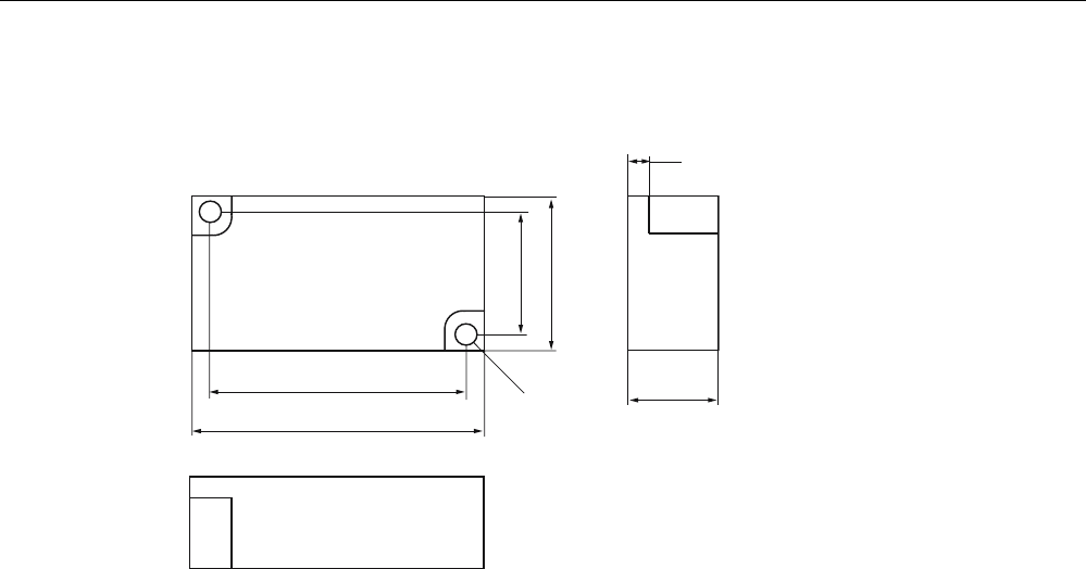
Flush-mounting of RF350T in metal:
Figure 6-8 RF350T flush-mounted in metal
The standard value for a is ≥ 20 mm. At lower values, the field data change significantly,
resulting in a reduction in the range.

Transponders
6.4 RF350T
SIMATIC RF300
134 System Manual, 09/2007, J31069 D0166-U001-A5-7618
6.4.3 Technical data
Table 6-3 Technical specifications for RF350T
Memory size 32 KB
Memory organization Blocks of 8 bits / 1 byte
Memory configuration
• Serial number (UID)
• Application memory
• OTP 1) memory
• 4-byte (fixed code)
• 32765 bytes r/w
• 20 bytes
Storage technology FRAM / EEPROM
MTBF (Mean Time Between Failures) in years 1201
Write cycles, at +40°C Virtually unlimited (>1010)
Read cycles Virtually unlimited (>1010)
Transmission rate
• Reading
• Writing
with RS422 reader:
Approx. 0.3 ms / byte
approx. 0.3 ms / byte
with IQ-Sense reader:
Approx. 20 ms / byte
approx. 25 ms / byte
Data retention > 10 years
Read/write distance dependent on the reader used
(see field data)
Multitag capability max. 4 transponders
Recommended spacing from metal can be directly mounted on metal
Power supply Inductive, without battery
Degree of protection to EN 60529
Shock to EN 60721-3-7
Vibration to EN 60721-3-7
Torsion and bending load
IP68
50 g
20 g
Not permitted permanently
Enclosure dimensions
Color
Material
Fixing
50 x 50 x 20 mm (L x W x H)
Anthracite
PA12
2 screws M4
Ambient temperature
• During operation
• During transport and storage
-25 °C to +85 °C
-40 °C to +85 °C
Weight Approx. 25 g
1) OTP: (One Time Programmable)
6.4.4 Ordering data
RF350T Order number:
32 KB FRAM (read/write) + 4 byte EEPROM
(read only), IP 68, -25 °C to +85 °C, dimensions
50 x 50 x 20 (LxWxH in mm)
6GT2800-5BD00
Transponders
6.4 RF350T
SIMATIC RF300
System Manual, 09/2007, J31069 D0166-U001-A5-7618 135
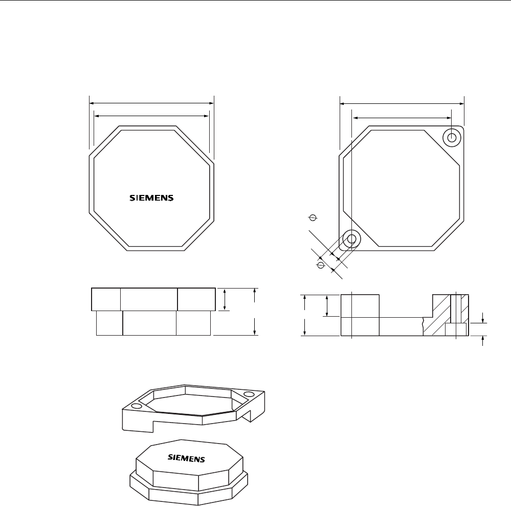
6.4.5 Dimension drawing
7KHWUDQVSRQGHUFDQEHPRXQWHGDVVKRZQZLWK
WKHIL[LQJIUDPH
,QVWDOODWLRQGLDJUDP
)L[LQJIUDPH
7UDQVSRQGHU
Figure 6-9 RF350T dimension drawing
Dimensions in mm
Transponders
6.5 RF360T
SIMATIC RF300
136 System Manual, 09/2007, J31069 D0166-U001-A5-7618
6.5 RF360T
6.5.1 Features
Transponder RF360T Features
Area of application Identification tasks on small assembly lines
in harsh industrial environments
Memory Read-only area (4 bytes UID)
Read/write memory (8 KB)
OTP 1) memory (20 bytes)
Read/write range Refer to SectionField data for
transponders, readers and antennas
(Page 37)
Mounting on metal Not possible; recommended distance from
metal ≥ 20 mm
1) OTP: One Time Programmable
Transponders
6.5 RF360T
SIMATIC RF300
System Manual, 09/2007, J31069 D0166-U001-A5-7618 137
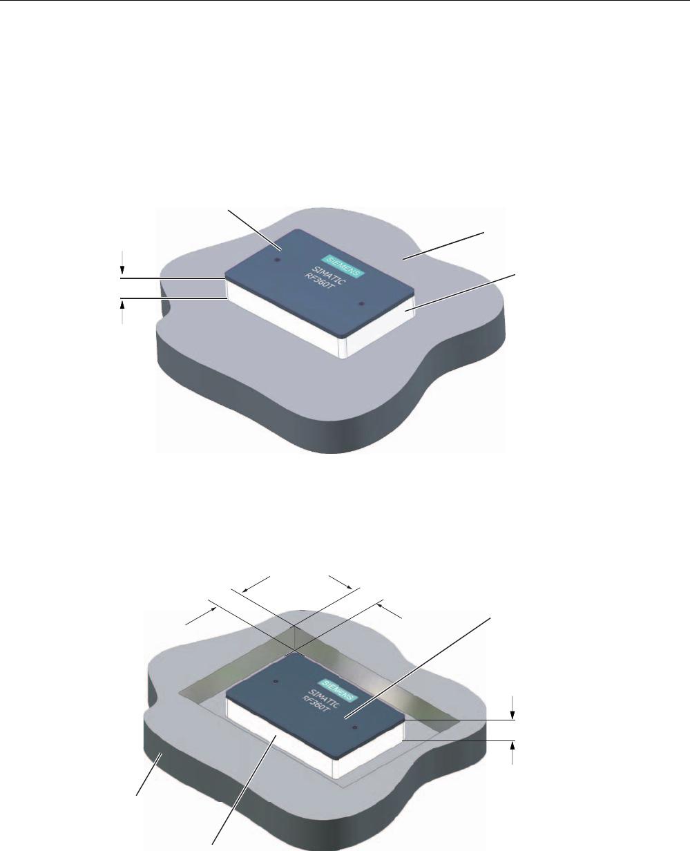
6.5.2 Metal-free area
Direct mounting of the RF360T on metal is not allowed. A distance ≥ 20 mm is
recommended. This can be achieved using the spacer 6GT2190-0AA00 in combination with
the fixing pocket 6GT2190-0AB00.
Mounting of RF360T on metal
K
0HWDO
1RQPHWDO
'DWDVWRUDJHXQLW
Figure 6-10 Mounting of RF360T with spacer
The standard value for h is ≥ 20 mm.
Flush-mounting of RF360T in metal:
1RQPHWDO
0HWDO
D
D
'DWDVWRUDJHXQLW
K
Figure 6-11 Flush-mounting of RF360T with spacer
The standard value for a is ≥ 20 mm. At lower values, the field data change significantly,
resulting in a reduction in the range.
Transponders
6.5 RF360T
SIMATIC RF300
138 System Manual, 09/2007, J31069 D0166-U001-A5-7618
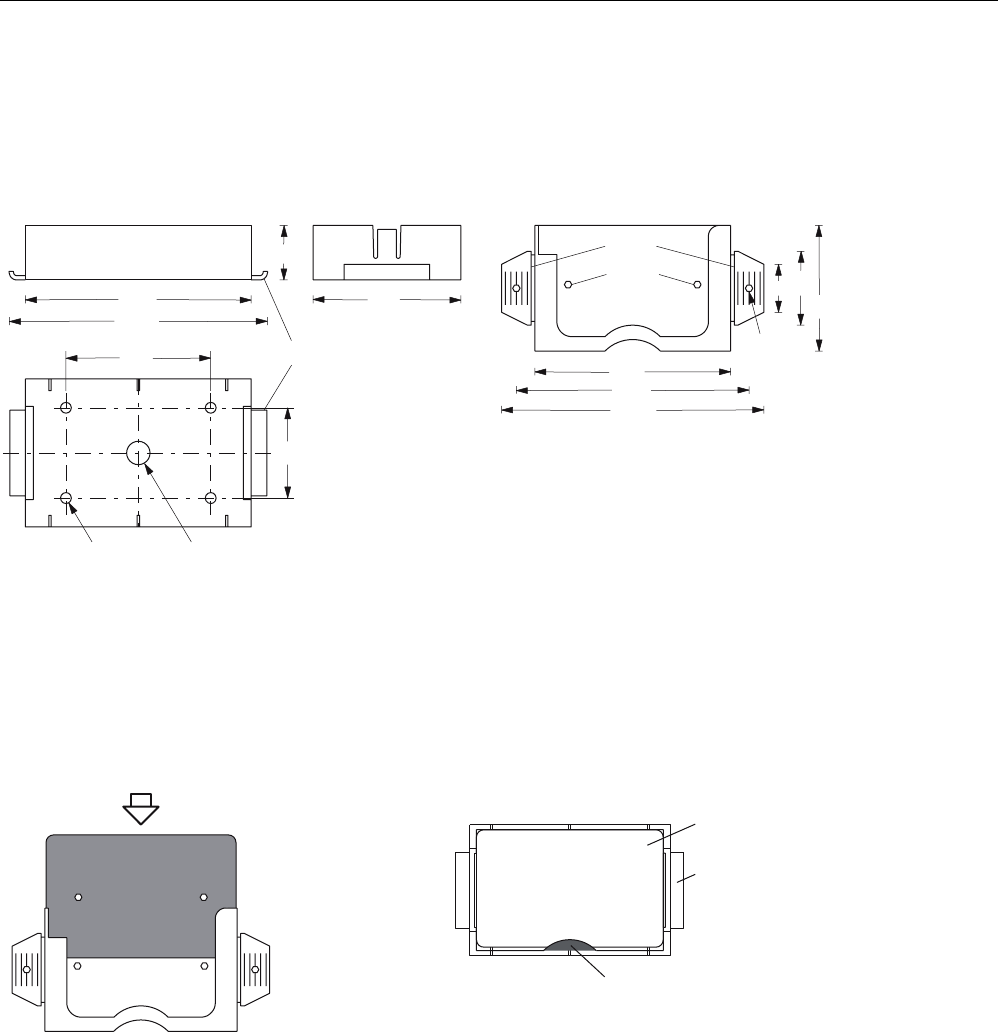
Dimensions of spacer and fixing pocket for RF360T
+ROGLQJFOLS
7KHVSDFHUFDQEHGLUHFWO\PRXQWHGRQPHWDO,QFRPELQDWLRQZLWKWKH
IL[LQJSRFNHWDQRQPHWDOGLVWDQFHRIPPUHVXOWVEHWZHHQWKHWUDQVSRQGHUDQGPHWDO
0RXQWLQJ
:LWKRUVFUHZV0
:LWKUXEEHUVRQWKHKROGLQJFOLSVHJRQPHVKER[HV
:LWKFDEOHWLHVRQWKHKROGLQJFOLSVHJRQPHVKER[HV
(DUV
+ROGLQJNQREV
'LPHQVLRQVNHWFK
6SDFHU*7$$ )L[LQJSRFNHW*7$%
7KHIL[LQJSRFNHWLVDWWDFKHGWRDQRQPHWDO
EDVHE\WKHHDUV7KLVFDQEHDFKLHYHG
ZLWK
6FUHZVLQWKHKROHVSURYLGHG
5LYHWVLQWKHKROHVSURYLGHG
1DLOVWKURXJKWKHKROHV
7DFNVWKURXJKWKHSODVWLFRIWKHHDUV
3XVKLQJLQWRWKHVSDFHUV
7KHHDUVFDQEHPRYHGWKURXJKXSWRr
7KHWUDQVSRQ
GHULV
LQVHUWHGLQWR
WKH
IL[LQJSRFNHW
/RFNLQJLVYLD
WKHKROGLQJ
NQREVLQWKH
IL[LQJSRFNHW 'DWDPHPRU\
6SDFHU
)L[LQJSRFNHW
7KHWUDQVSRQGHULVLQVHUWHGLQWRWKH
IL[LQJSRFNHW7KHHDUVDUHPRYHGE\
rDQGLQVHUWHGLQWRWKHVSDFHU7KH
IL[LQJSRFNHWPXVWEH
DOLJQHGVXFKWKDWLWFRYHUV
WKHWUDQVSRQGHUVHH)LJXUH/RFNLQJ
LVDXWRPDWLF
7UDQVSRQGHUZLWKIL[LQJSRFNHW 7UDQVSRQGHUZLWKIL[LQJSRFNHWDQG
VSDFHUFRQQHFWHGWRJHWKHU
0DWHULDO3$
5HDVVHPEO\LQVWUXFWLRQV
6,(0(16
Figure 6-12 Dimensions of spacer and fixing pocket for RF360T

Transponders
6.5 RF360T
SIMATIC RF300
System Manual, 09/2007, J31069 D0166-U001-A5-7618 139
6.5.3 Technical data
Table 6-4 Technical specifications for RF360T
Memory size 8 KB
Memory organization Blocks of 8 bits / 1 byte
Memory configuration
• Serial number (UID)
• Application memory
• OTP 1) memory
• 4-byte (fixed code)
• 8189 bytes r/w
• 20 bytes
Storage technology FRAM / EEPROM
MTBF (Mean Time Between Failures) in years 1201
Write cycles, at +40°C Virtually unlimited (>1010)
Read cycles Virtually unlimited (>1010)
Transmission rate
• Reading
• Writing
with RS422 reader:
Approx. 0.3 ms / byte
approx. 0.3 ms / byte
with IQ-Sense reader:
Approx. 20 ms / byte
approx. 25 ms / byte
Data retention > 10 years
Read/write distance dependent on the reader used
(see field data)
Multitag capability max. 4 transponders
Recommended spacing from metal ≥ 20 mm; e.g. using spacer 6GT2190-0AA00 in
conjunction with fixing pocket 6GT2190-0AB00
Power supply Inductive, without battery
Degree of protection to EN 60529
Shock to EN 60721-3-7
Vibration to EN 60721-3-7
Torsion and bending load
IP67
50 g
20 g
Not permitted permanently
Enclosure dimensions
Color
Material
Fixing
85.8 x 54.8 x 2.5 mm (L x W x H)
Anthracite
PA12
2 screws (M3) or with fixing pocket 6GT2190-
0AB00
Ambient temperature
• During operation
• During transport and storage
-25°C to +75°C
-40°C to +85°C
Weight Approx. 25 g
1) OTP: (One Time Programmable)
6.5.4 Ordering data
RF360T Order number
8 KB FRAM (read/write) + 4 byte EEPROM (read
only), IP 67, -25 °C to +75 °C, dimensions 85.8 x
54.8 x 2.5 (LxWxH in mm)
6GT2800-4AC00
Transponders
6.5 RF360T
SIMATIC RF300
140 System Manual, 09/2007, J31069 D0166-U001-A5-7618
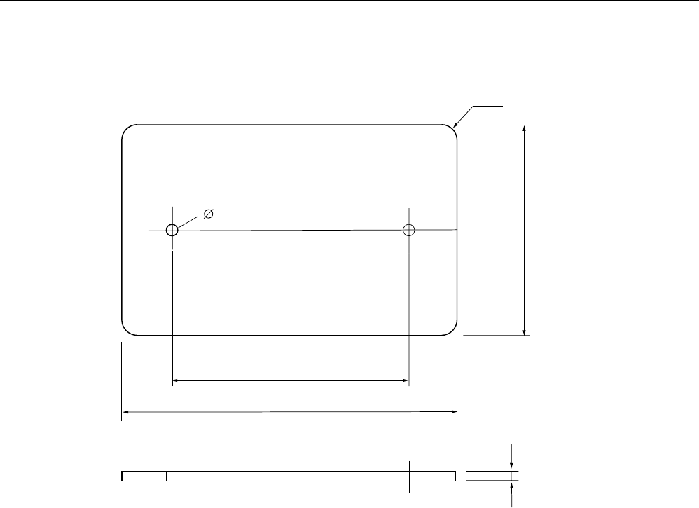
6.5.5 Dimension drawing
5
Figure 6-13 RF360T dimension drawing
Dimensions in mm
Transponders
6.6 RF370T
SIMATIC RF300
System Manual, 09/2007, J31069 D0166-U001-A5-7618 141
6.6 RF370T
6.6.1 Features
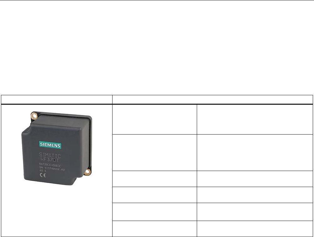
The SIMATIC RF370T transponder is a passive (i.e. battery-free) data carrier in a square
type of construction.
SIMATIC RF370T transponder Features
Area of application Identification tasks on assembly lines in
harsh industrial environments, suitable for
larger ranges,
e.g. automotive industry
Memory Read-only area:
4 byte UID
write/read memory:
32/64 KB
OTP 1) memory: 20 bytes
Write/read range Refer to SectionField data for transponders,
readers and antennas (Page 37)
Assembly Direct assembly on metal or flush-mounting
is possible (with two M5 screws)
Degree of protection IP68
IPx9K
High resistance to mineral oils, lubricants and cleaning
agents
1) OTP: One Time Programmable; single write
Transponders
6.6 RF370T
SIMATIC RF300
142 System Manual, 09/2007, J31069 D0166-U001-A5-7618
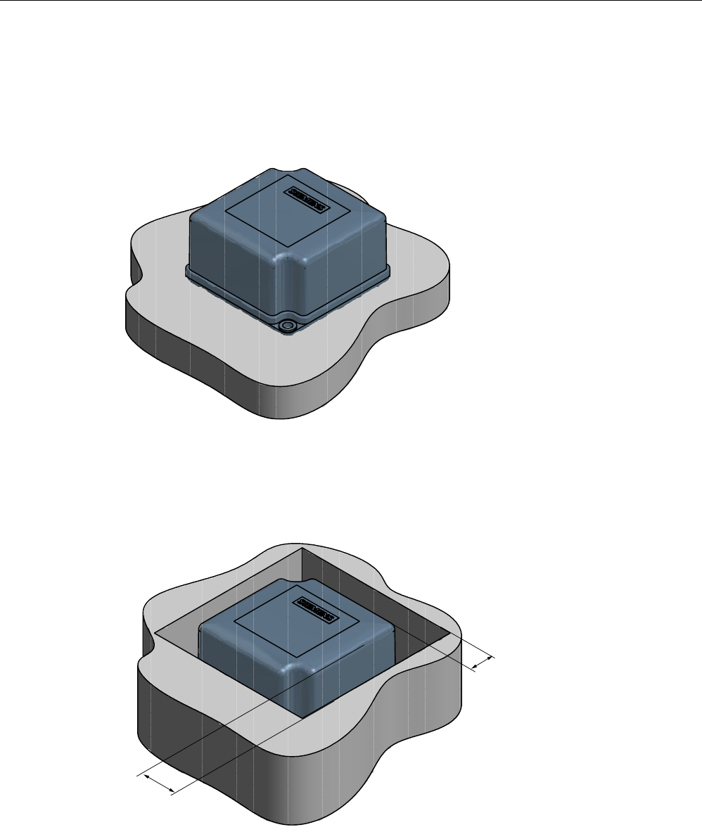
6.6.2 Metal-free area
Direct mounting of the RF370T on metal is permitted.
Mounting of RF370T on metal
Figure 6-14 Mounting of RF370T on metal
Flush-mounting of RF370T in metal:
D
D
Figure 6-15 RF370T flush-mounted in metal
The standard value for a is ≥ 20 mm. At lower values, the field data change significantly,
resulting in a reduction in the range.

Transponders
6.6 RF370T
SIMATIC RF300
System Manual, 09/2007, J31069 D0166-U001-A5-7618 143
6.6.3 Mounting instructions
It is essential that you observe the instructions in the Section Installation guidelines
(Page 54).
Properties Description
Type of installation Screw fixing (two M5 screws)
Tightening torque < 1.2 Nm (at room temperature)

Transponders
6.6 RF370T
SIMATIC RF300
144 System Manual, 09/2007, J31069 D0166-U001-A5-7618
6.6.4 Technical specifications
6.6.4.1 Technical data for RF370T with 32 KB FRAM
Table 6-5 Technical specifications for RF370T with 32 KB FRAM
Characteristic Description
Memory size 32KB
Memory organization Blocks of 8 bits / 1 byte
Serial number 4-byte (fixed code)
Application memory 32765 bytes r/w
Memory configuration
OTP 1) memory 20 bytes
Storage technology FRAM / EEPROM
MTBF (Mean Time Between Failures)
in years
1189
Write cycles, at +40°C Virtually unlimited (>1010)
Read cycles Practically unlimited (>1010)
Read approx. 0.3 ms/byte Transmission rate
Write approx. 0.3 ms/byte
Data retention in years > 10
Read/write distance dependent on the reader used (see field data)
Multitag capability max. 4 transponders
Recommended spacing from metal can be directly mounted on metal
Power supply Inductive, without battery
Degree of protection to EN 60529 IPx9K
Shock resistant to EN 60721-3-7 50 g
Vibration resistant to EN 60721-3-7 20 g
Torsion and bending load Not permissible continuously
Housing dimensions 75 x 75 x 40 mm (L x W x H)
Color Anthracite
Material PA12
Fixing Two M5 screws
During operation -25 °C to +85 °C Ambient temperature
During transport and storage -40°C to +85°C
Weight Approx. 200 g
1) OTP: One Time Programmable

Transponders
6.6 RF370T
SIMATIC RF300
System Manual, 09/2007, J31069 D0166-U001-A5-7618 145
6.6.4.2 Technical data for RF370T with 64 KB FRAM
Table 6-6 Technical specifications for RF370T with 64 KB FRAM
Characteristic Description
Memory size 64 KB
Memory organization Blocks of 8 bits / 1 byte
Serial number 4-byte (fixed code)
Application memory 65276 bytes r/w
Memory configuration
OTP 1) memory 20 bytes
Storage technology FRAM / EEPROM
MTBF (Mean Time Between Failures)
in years
1189
Write cycles, at +40°C Practically unlimited (>1010)
Read cycles Practically unlimited (>1010)
Read approx. 0.3 ms/byte Transmission rate
Write approx. 0.3 ms/byte
Data retention in years > 10
Read/write distance dependent on the reader used (see field data)
Multitag capability max. 4 transponders
Recommended spacing from metal Can be directly mounted on metal
Power supply Inductive, without battery
Degree of protection to EN 60529 IPx9K
Shock resistant to EN 60721-3-7 50 g
Vibration resistant to EN 60721-3-7 20 g
Torsion and bending load Not permissible continuously
Housing dimensions 75 x 75 x 40 mm (L x W x H)
Color Anthracite
Material PA12
Fixing Two M5 screws
During operation -25 °C to +85 °C Ambient temperature
During transport and storage -40°C to +85°C
Weight Approx. 200 g
1) OTP: One Time Programmable

Transponders
6.6 RF370T
SIMATIC RF300
146 System Manual, 09/2007, J31069 D0166-U001-A5-7618
6.6.5 Ordering data
Ordering data Order Number
SIMATIC RF300
RF370T transponder
32 KB FRAM, -25 to +85 degrees C,
IP68; 75 x 75 x 40 mm
6GT2800-5BE00
SIMATIC RF300
RF370T transponder
64 KB FRAM, -25 to +85 degrees C,
IP68; 75 x 75 x 40 mm
6GT2800-6BE00
Transponders
6.6 RF370T
SIMATIC RF300
System Manual, 09/2007, J31069 D0166-U001-A5-7618 147
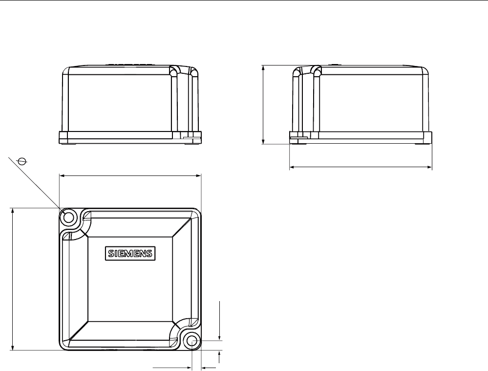
6.6.6 Dimensional drawing
Figure 6-16 RF370T dimension drawing
Dimensions in mm (inches in brackets)
Transponders
6.7 RF380T
SIMATIC RF300
148 System Manual, 09/2007, J31069 D0166-U001-A5-7618
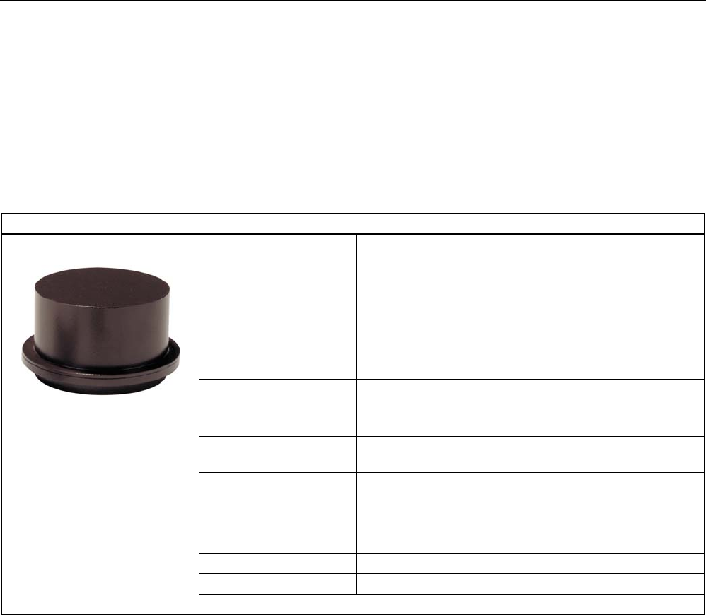
6.7 RF380T
6.7.1 Features
The SIMATIC RF380T transponder is an extremely rugged and heat-resistant round data
carrier suitable e.g. for applications in the automotive industry.
SIMATIC RF380T transponder Features
Area of application Identification tasks in applications (e.g. automotive industry)
with cyclic high temperature stress > 85 °C and < 220 °C
Typical applications:
• Primer coat, electrolytic dip area, cataphoresis with the
associated drying furnaces
• Top coat area with drying furnaces
• Washing areas at temperatures > 85°C
• Other applications with higher temperatures
Memory • Read-only area (4 bytes UID)
• Read/write memory (32 KB)
• OTP 1) memory (20 bytes)
Write/read range Refer to SectionField data for transponders, readers and
antennas (Page 37)
Assembly • Direct assembly on metal or flush-mounting is possible.
• The transponder can be secured using a special holder
(see installation guidelines, section on RF380T).
The tag size is designed such that it can be secured on
a skid or also directly on a body.
Degree of protection IP 68
High resistance to mineral oils, lubricants and cleaning agents
1) OTP: One Time Programmable
Transponders
6.7 RF380T
SIMATIC RF300
System Manual, 09/2007, J31069 D0166-U001-A5-7618 149
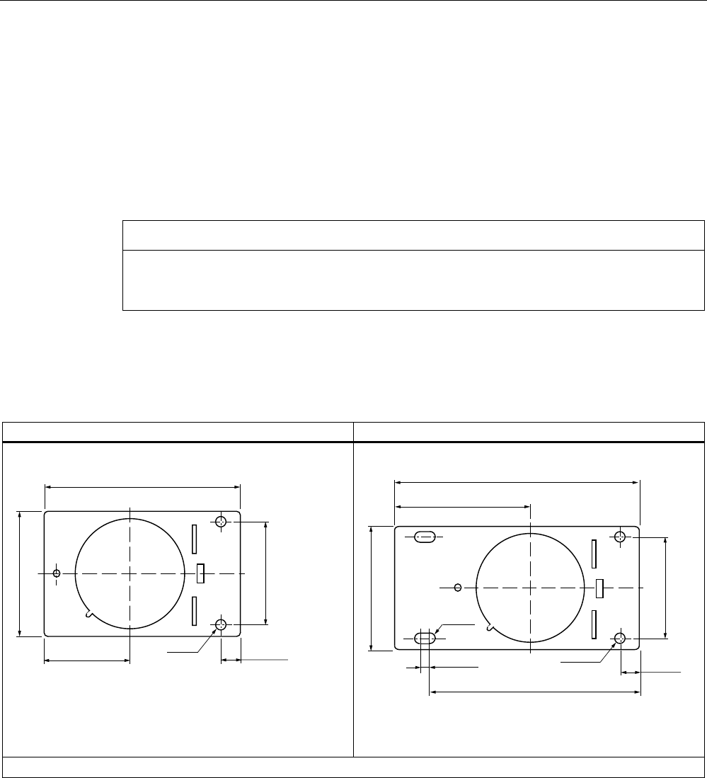
6.7.2 Installation guidelines for RF380T
It is essential that you observe the instructions in the Section Installation guidelines
(Page 54).
The following section only deals with features specific to the SIMATIC RF380T.
6.7.2.1 Mounting instructions
CAUTION
You are strongly recommended to only use the tag with the original holder specified. Only
this holder guarantees that the data memory observes the listed values for shock, vibration
and temperature. A protective cover is recommendable for applications in paint shops.
Data memory support
Short version (6GT2 090-0QA00) Long version (6GT2090-0QA00-0AX3)
Dimensions in mm, inches in brackets
Dimensions in mm, inches in brackets
Material: V2A sheet-steel with thickness 2.5 mm BI 2.5 DIN 59382 1.4541
Transponders
6.7 RF380T
SIMATIC RF300
150 System Manual, 09/2007, J31069 D0166-U001-A5-7618
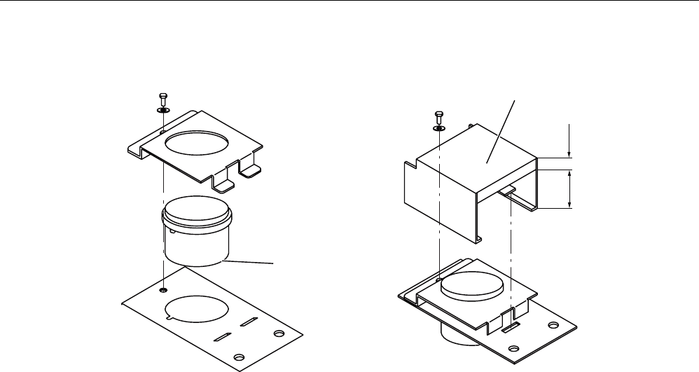
Assembly of data memory with support
$QWHQQDVLGHRIWDJ
&RYHURSWLRQDO
*74%
Figure 6-17 Assembly of tag with support
Scope of supply
The support is provided with all mounting parts and a mounting diagram. Mounting screws
for securing the support are not included. The mounting screws are of diameter M 10. The
minimum length is 25 mm. The optional cover can be used for the long and short versions of
the support.