Siemens RF380R02 RFID Reader 13.56 MHz User Manual SIMATIC RF300
Siemens AG RFID Reader 13.56 MHz SIMATIC RF300
Siemens >
Contents
- 1. SYH_RF300_76_Part 1
- 2. SYH_RF300_76_Part 2
- 3. SYH_RF300_76_Part 3
SYH_RF300_76_Part 1

___________________
___________________
___________________
___________________
___________________
___________________
___________________
___________________
___________________
___________________
___________________
SIMATIC Ident
RFID systems
SIMATIC RF300
System Manual
07/2017
C79000
-G8976-C345-07
Introduction
1
Safety information
2
System overview
3
Planning the RF300 system
4
Readers
5
Antennas
6
RF300 transponder
7
ISO transponder
8
System integration
9
System diagnostics
10
Appendix
A

Siemens AG
Division Process Industries and Drives
Postfach 48 48
90026 NÜRNBERG
GERMANY
Ⓟ
07/2017 Subject to change
Copyright © Siemens AG 2005 - 2017.
All rights reserved
Legal information
Warning notice system
This manual contains notices you have to observe in order to ensure your personal safety, as well as to prevent
damage to property. The notices referring to your personal safety are highlighted in the manual by a safety alert
symbol, notices referring only to property damage have no safety alert symbol. These notices shown below are
graded according to the degree of danger.
DANGER
indicates that death or severe personal injury will result if proper precautions are not taken.
WARNING
indicates that death or severe personal injury may result if proper precautions are not taken.
CAUTION
indicates that minor personal injury can result if proper precautions are not taken.
NOTICE
indicates that property damage can result if proper precautions are not taken.
If more than one degree of danger is present, the warning notice representing the highest degree of danger will
be used. A notice warning of injury to persons with a safety alert symbol may also include a warning relating to
property damage.
Qualified Personnel
The product/system described in this documentation may be operated only by
personnel qualified
for the specific
task in accordance with the relevant documentation, in particular its warning notices and safety instructions.
Qualified personnel are those who, based on their training and experience, are capable of identifying risks and
avoiding potential hazards when working with these products/systems.
Proper use of Siemens products
Note the following:
WARNING
Siemens products may only be used for the applications described in the catalog and in the relevant technical
documentation. If products and components from other manufacturers are used, these must be recommended
or approved by Siemens. Proper transport, storage, installation, assembly, commissioning, operation and
maintenance are required to ensure that the products operate safely and without any problems. The permissible
ambient conditions must be complied with. The information in the relevant documentation must be observed.
Trademarks
All names identified by ® are registered trademarks of Siemens AG. The remaining trademarks in this publication
may be trademarks whose use by third parties for their own purposes could violate the rights of the owner.
Disclaimer of Liability
We have reviewed the contents of this publication to ensure consistency with the hardware and software
described. Since variance cannot be precluded entirely, we cannot guarantee full consistency. However, the
information in this publication is reviewed regularly and any necessary corrections are included in subsequent
editions.
SIMATIC RF300
System Manual, 07/2017, C79000-G8976-C345-07 3
Table of contents
1 Introduction ........................................................................................................................................... 15
1.1 Navigating in the system manual ............................................................................................ 15
1.2 Preface .................................................................................................................................... 15
2 Safety information ................................................................................................................................. 19
3 System overview ................................................................................................................................... 23
3.1 RFID systems ......................................................................................................................... 23
3.2 SIMATIC RF300 ...................................................................................................................... 24
3.2.1 System overview of SIMATIC RF300 ..................................................................................... 24
3.2.2 RFID components and their function ...................................................................................... 25
3.2.3 Application areas of RF300 .................................................................................................... 33
3.3 System configuration .............................................................................................................. 34
3.3.1 Overview ................................................................................................................................. 34
3.3.2 Assembly line example: Use of RF300 transponders ............................................................. 34
3.3.3 Example of container and cardboard container handling: Use of ISO transponders ............. 36
4 Planning the RF300 system .................................................................................................................. 39
4.1 Fundamentals of application planning .................................................................................... 39
4.1.1 Selection criteria for SIMATIC RF300 components ................................................................ 39
4.1.2 Transmission window and read/write distance ....................................................................... 39
4.1.3 Width of the transmission window .......................................................................................... 42
4.1.4 Impact of secondary fields ...................................................................................................... 43
4.1.5 Setup help of the readers of the second generation ............................................................... 46
4.1.6 Permissible directions of motion of the transponder ............................................................... 47
4.1.7 Operation in static and dynamic mode ................................................................................... 47
4.1.8 Dwell time of the transponder ................................................................................................. 49
4.1.9 Communication between communications module, reader and transponder ........................ 50
4.2 Field data for transponders, readers and antennas ................................................................ 51
4.2.1 Field data of RF300 transponders .......................................................................................... 52
4.2.2 Field data of ISO transponders (MDS D) ................................................................................ 56
4.2.3 Field data of ISO transponders (MDS E) ................................................................................ 61
4.2.4 Minimum clearances ............................................................................................................... 64
4.3 Installation guidelines.............................................................................................................. 67
4.3.1 Overview ................................................................................................................................. 67
4.3.2 Reduction of interference due to metal ................................................................................... 67
4.3.3 Effects of metal on different transponders and readers .......................................................... 70
4.3.4 Impact on the transmission window by metal ......................................................................... 70
4.3.4.1 Impact on the transmission window by metal ......................................................................... 71
4.3.4.2 RF340R ................................................................................................................................... 75
4.3.4.3 RF350R ................................................................................................................................... 79
4.3.4.4 RF380R ................................................................................................................................... 93
4.3.4.5 RF382R ...................................................................................................................................
96

Table of contents
SIMATIC RF300
4 System Manual, 07/2017, C79000-G8976-C345-07
4.4 Chemical resistance of the readers and transponders .......................................................... 97
4.4.1 Readers .................................................................................................................................. 97
4.4.1.1 Overview of the readers and their housing materials ............................................................ 97
4.4.1.2 Polyamide 12 ......................................................................................................................... 97
4.4.2 Transponder ........................................................................................................................... 99
4.4.2.1 Overview of the transponders and their housing materials ................................................... 99
4.4.2.2 Polyamide 6 and Polyamide 6.6 GF30 ................................................................................ 101
4.4.2.3 Polyamide 12 ....................................................................................................................... 102
4.4.2.4 Polyphenylene sulfide (PPS) ............................................................................................... 104
4.4.2.5 Polycarbonate (PC) .............................................................................................................. 105
4.4.2.6 Polyvinyl chloride (PVC) ...................................................................................................... 106
4.4.2.7 Epoxy resin .......................................................................................................................... 106
4.5 Guidelines for electromagnetic compatibility (EMC) ............................................................ 109
4.5.1 Overview .............................................................................................................................. 109
4.5.2 What does EMC mean? ....................................................................................................... 110
4.5.3 Basic rules ............................................................................................................................ 111
4.5.4 Propagation of electromagnetic interference ....................................................................... 112
4.5.5 Cabinet configuration ........................................................................................................... 116
4.5.6 Prevention of interference sources ...................................................................................... 119
4.5.7 Equipotential bonding .......................................................................................................... 120
4.5.8 Cable shielding..................................................................................................................... 121
5 Readers ............................................................................................................................................... 123
5.1 SIMATIC RF310R ................................................................................................................ 124
5.1.1 Features ............................................................................................................................... 124
5.1.2 RF310R ordering data ......................................................................................................... 124
5.1.3 Pin assignment RF310R with RS-422 interface .................................................................. 125
5.1.4 LED operating display .......................................................................................................... 125
5.1.5 Ensuring reliable data exchange .......................................................................................... 125
5.1.6 Metal-free area ..................................................................................................................... 126
5.1.7 Minimum distance between RF310R readers ...................................................................... 126
5.1.8 Technical specifications ....................................................................................................... 127
5.1.9 Approvals ............................................................................................................................. 129
5.1.10 Dimension drawing .............................................................................................................. 130
5.2 SIMATIC RF310R with Scanmode ...................................................................................... 131
5.2.1 Features ............................................................................................................................... 131
5.2.2 Ordering data for RF310R with Scanmode .......................................................................... 131
5.2.3 Pin assignment RF310R special version Scanmode RS-422 interface ............................... 132
5.2.4 LED operating display .......................................................................................................... 132
5.2.5 Ensuring reliable data exchange .......................................................................................... 132
5.2.6 Metal-free area ..................................................................................................................... 133
5.2.7 Minimum distance between several readers ....................................................................... 133
5.2.8 Technical specifications ....................................................................................................... 134
5.2.9 Approvals ............................................................................................................................. 135
5.2.10 Dimension drawing .............................................................................................................. 136
5.3 SIMATIC RF310R - 2nd generation ..................................................................................... 137
5.3.1 Features ............................................................................................................................... 137
5.3.2 Ordering data ....................................................................................................................... 137
5.3.3 Pin assignment of the RS-422 interface .............................................................................. 138
5.3.4 LED operating display .......................................................................................................... 138
5.3.5 Ensuring reliable data exchange .......................................................................................... 139

Table of contents
SIMATIC RF300
System Manual, 07/2017, C79000-G8976-C345-07 5
5.3.6 Metal-free area ...................................................................................................................... 139
5.3.7 Minimum distance between RF310R readers ...................................................................... 140
5.3.8 Technical specifications ........................................................................................................ 141
5.3.9 Approvals .............................................................................................................................. 142
5.3.10 Dimension drawing ............................................................................................................... 144
5.3.11 Using the reader in hazardous area ..................................................................................... 144
5.3.11.1 Using the reader in hazardous area for gases ..................................................................... 148
5.3.11.2 Using the reader in hazardous area for dust ........................................................................ 148
5.3.11.3 Installation and operating conditions for hazardous areas: .................................................. 149
5.4 SIMATIC RF340R/RF350R .................................................................................................. 150
5.4.1 SIMATIC RF340R ................................................................................................................. 150
5.4.1.1 Features ................................................................................................................................ 150
5.4.1.2 Ordering data for RF340R .................................................................................................... 150
5.4.1.3 Pin assignment of RF340R RS422 interface ........................................................................ 151
5.4.1.4 LED operating display ........................................................................................................... 151
5.4.1.5 Ensuring reliable data exchange .......................................................................................... 151
5.4.1.6 Metal-free area ...................................................................................................................... 152
5.4.1.7 Minimum distance between RF340R readers ...................................................................... 152
5.4.1.8 Technical specifications ........................................................................................................ 153
5.4.1.9 Approvals .............................................................................................................................. 155
5.4.1.10 Dimension drawing ............................................................................................................... 156
5.4.2 SIMATIC RF350R ................................................................................................................. 157
5.4.2.1 Features ................................................................................................................................
157
5.4.2.2 Ordering data for RF350R .................................................................................................... 157
5.4.2.3 Pin assignment of RF350R RS422 interface ........................................................................ 158
5.4.2.4 LED operating display ........................................................................................................... 158
5.4.2.5 Ensuring reliable data exchange .......................................................................................... 158
5.4.2.6 Metal-free area ...................................................................................................................... 158
5.4.2.7 Technical specifications ........................................................................................................ 159
5.4.2.8 Approvals .............................................................................................................................. 161
5.4.2.9 Dimension drawing ............................................................................................................... 162
5.4.3 Use of the reader in hazardous areas .................................................................................. 163
5.4.3.1 Use of the readers in hazardous areas for gases ................................................................. 164
5.4.3.2 Use of the readers in hazardous areas for dusts .................................................................. 164
5.4.3.3 Installation and operating conditions for the hazardous area ............................................... 165
5.5 SIMATIC RF340R/RF350R - 2nd generation ....................................................................... 166
5.5.1 SIMATIC RF340R - 2nd generation ...................................................................................... 166
5.5.1.1 Features ................................................................................................................................ 166
5.5.1.2 Ordering data ........................................................................................................................ 166
5.5.1.3 Pin assignment of the RS-422 interface ............................................................................... 167
5.5.1.4 LED operating display ........................................................................................................... 167
5.5.1.5 Ensuring reliable data exchange .......................................................................................... 167
5.5.1.6 Metal-free area ...................................................................................................................... 168
5.5.1.7 Minimum distance between RF340R readers ...................................................................... 168
5.5.1.8 Technical specifications ........................................................................................................ 169
5.5.1.9 Approvals .............................................................................................................................. 171
5.5.1.10 Dimension drawing ............................................................................................................... 172
5.5.2 SIMATIC RF350R - 2nd generation ...................................................................................... 173
5.5.2.1 Features ................................................................................................................................ 173
5.5.2.2 Ordering data ........................................................................................................................ 173
5.5.2.3 Pin assignment of the RS-422 interface ............................................................................... 174

Table of contents
SIMATIC RF300
6 System Manual, 07/2017, C79000-G8976-C345-07
5.5.2.4 LED operating display .......................................................................................................... 174
5.5.2.5 Ensuring reliable data exchange .......................................................................................... 174
5.5.2.6 Metal-free area ..................................................................................................................... 175
5.5.2.7 Technical specifications ....................................................................................................... 175
5.5.2.8 Approvals ............................................................................................................................. 177
5.5.2.9 Dimension drawing .............................................................................................................. 178
5.5.3 Using the readers in a hazardous area ................................................................................ 179
5.5.3.1 Using the reader in hazardous area for gases ..................................................................... 182
5.5.3.2 Using the reader in hazardous area for dust ....................................................................... 182
5.5.3.3 Installation and operating conditions for hazardous areas: ................................................. 183
5.6 SIMATIC RF380R ................................................................................................................ 184
5.6.1 Features ............................................................................................................................... 184
5.6.2 RF380R ordering data ......................................................................................................... 184
5.6.3 Pin assignment of RF380R RS-232/RS-422 interface......................................................... 184
5.6.4 LED operating display .......................................................................................................... 185
5.6.5 Ensuring reliable data exchange .......................................................................................... 185
5.6.6 Metal-free area ..................................................................................................................... 186
5.6.7 Minimum distance between RF380R readers ...................................................................... 186
5.6.8 Technical specifications ....................................................................................................... 187
5.6.9 Approvals ............................................................................................................................. 189
5.6.10 Dimension drawing .............................................................................................................. 190
5.6.11 Use of the reader in a hazardous ......................................................................................... 190
5.6.11.1 Use of the reader in a hazardous area ................................................................................ 190
5.6.11.2 Use of the reader in hazardous areas for gases .................................................................. 191
5.6.11.3 Installation and operating conditions for hazardous areas: ................................................. 192
5.7 SIMATIC RF380R with Scanmode ...................................................................................... 193
5.7.1 Features ............................................................................................................................... 193
5.7.2 Ordering data for RF380R with Scanmode .......................................................................... 193
5.7.3 Pin assignment RF380R Scanmode RS-232 interface........................................................ 194
5.7.4 LED operating display .......................................................................................................... 194
5.7.5 Ensuring reliable data exchange .......................................................................................... 194
5.7.6 Metal-free area ..................................................................................................................... 195
5.7.7 Minimum distance between several RF380R Scanmode readers ....................................... 195
5.7.8 Technical specifications ....................................................................................................... 196
5.7.9 Approvals ............................................................................................................................. 197
5.7.10 Certificates and Approvals ................................................................................................... 198
5.7.11 Dimension drawing .............................................................................................................. 199
5.8 SIMATIC RF380R - 2nd generation ..................................................................................... 200
5.8.1 Features ............................................................................................................................... 200
5.8.2 RF380R ordering data ......................................................................................................... 200
5.8.3 Pin assignment of RF380R RS-232/RS-422 interface......................................................... 201
5.8.4 LED operating display .......................................................................................................... 201
5.8.5 Ensuring reliable data exchange .......................................................................................... 202
5.8.6 Metal-free area ..................................................................................................................... 202
5.8.7 Minimum distance between RF380R readers ...................................................................... 203
5.8.8 Technical specifications ....................................................................................................... 204
5.8.9 Approvals ............................................................................................................................. 205
5.8.10 Dimension drawing .............................................................................................................. 207
5.8.11 Using the reader in hazardous area..................................................................................... 207
5.8.11.1 Using the reader in hazardous area for gases ..................................................................... 210
5.8.11.2 Using the reader in hazardous area for dust ....................................................................... 211

Table of contents
SIMATIC RF300
System Manual, 07/2017, C79000-G8976-C345-07 7
5.8.11.3 Installation and operating conditions for hazardous areas: .................................................. 211
5.9 SIMATIC RF382R with Scanmode ....................................................................................... 212
5.9.1 Characteristics ...................................................................................................................... 212
5.9.2 RF382R with Scanmode ordering data................................................................................. 212
5.9.3 Pin assignment RF382R Scanmode RS232 interface .......................................................... 213
5.9.4 LED operating display ........................................................................................................... 213
5.9.5 Ensuring reliable data exchange .......................................................................................... 213
5.9.6 Mounting on metal ................................................................................................................ 214
5.9.7 Minimum distance between several RF382R Scanmode readers ....................................... 214
5.9.8 Transmission window............................................................................................................ 214
5.9.9 Technical specifications ........................................................................................................ 218
5.9.10 Approvals .............................................................................................................................. 219
5.9.11 Dimensional diagram ............................................................................................................ 220
6 Antennas ............................................................................................................................................ 221
6.1 Features ................................................................................................................................ 221
6.2 Ordering data ........................................................................................................................ 224
6.3 Ensuring reliable data exchange .......................................................................................... 224
6.4 Metal-free area ...................................................................................................................... 225
6.5 Minimum distance between antennas .................................................................................. 228
6.6 Technical specifications ........................................................................................................ 229
6.7 Dimensional drawings ........................................................................................................... 230
7 RF300 transponder ............................................................................................................................. 233
7.1 Memory configuration of the RF300 transponders ............................................................... 234
7.2 SIMATIC RF320T ................................................................................................................. 236
7.2.1 Features ................................................................................................................................ 236
7.2.2 Ordering data ........................................................................................................................ 236
7.2.3 Mounting on metal ................................................................................................................ 237
7.2.4 Technical data ....................................................................................................................... 238
7.2.5 Dimension drawing ............................................................................................................... 239
7.3 SIMATIC RF330T ................................................................................................................. 240
7.3.1 Features ................................................................................................................................ 240
7.3.2 Ordering data ........................................................................................................................ 240
7.3.3 Mounting on/in metal............................................................................................................. 240
7.3.4 Technical specifications ........................................................................................................ 242
7.3.5 Dimension drawing ............................................................................................................... 243
7.4 SIMATIC RF340T ................................................................................................................. 244
7.4.1 Features ................................................................................................................................ 244
7.4.2 Ordering data ........................................................................................................................ 244
7.4.3 Mounting on metal ................................................................................................................ 245
7.4.4 Technical specifications ........................................................................................................ 246
7.4.5 Dimension drawing ............................................................................................................... 247
7.5 SIMATIC RF350T ................................................................................................................. 248
7.5.1 Features ................................................................................................................................ 248
7.5.2 Ordering data ........................................................................................................................ 248
7.5.3 Mounting on metal ................................................................................................................ 249

Table of contents
SIMATIC RF300
8 System Manual, 07/2017, C79000-G8976-C345-07
7.5.4 Mounting options .................................................................................................................. 250
7.5.5 Technical data ...................................................................................................................... 251
7.5.6 Dimension drawing .............................................................................................................. 252
7.6 SIMATIC RF360T................................................................................................................. 253
7.6.1 Features ............................................................................................................................... 253
7.6.2 Ordering data ....................................................................................................................... 253
7.6.3 Mounting on metal ............................................................................................................... 254
7.6.4 Technical data ...................................................................................................................... 257
7.6.5 Dimension drawing .............................................................................................................. 258
7.7 SIMATIC RF370T................................................................................................................. 259
7.7.1 Features ............................................................................................................................... 259
7.7.2 Ordering data ....................................................................................................................... 259
7.7.3 Mounting on metal ............................................................................................................... 260
7.7.4 Mounting instructions ........................................................................................................... 261
7.7.5 Technical specifications ....................................................................................................... 261
7.7.6 Dimensional drawing ............................................................................................................ 262
7.8 SIMATIC RF380T................................................................................................................. 263
7.8.1 Features ............................................................................................................................... 263
7.8.2 Ordering data ....................................................................................................................... 263
7.8.3 Installation guidelines for RF380T ....................................................................................... 264
7.8.3.1 Mounting instructions ........................................................................................................... 264
7.8.3.2 Metal-free area ..................................................................................................................... 267
7.8.4 Configuring instructions ....................................................................................................... 268
7.8.4.1 Temperature dependence of the transmission window ....................................................... 268
7.8.4.2 Temperature response in cyclic operation ........................................................................... 268
7.8.5 Use of the transponder in the Ex protection area ................................................................ 271
7.8.5.1 Use of the transponder in hazardous areas for gases ......................................................... 272
7.8.5.2 Installation and operating conditions for the hazardous area .............................................. 272
7.8.6 Cleaning the mobile data memory ....................................................................................... 272
7.8.7 Technical specifications ....................................................................................................... 273
7.8.8 Dimensional drawing ............................................................................................................ 274
8 ISO transponder .................................................................................................................................. 275
8.1 Memory configuration of ISO the transponders ................................................................... 276
8.2 MDS D100 ............................................................................................................................ 278
8.2.1 Characteristics ..................................................................................................................... 278
8.2.2 Ordering data ....................................................................................................................... 278
8.2.3 Metal-free area ..................................................................................................................... 279
8.2.4 Technical data ...................................................................................................................... 281
8.2.5 Dimension drawing .............................................................................................................. 282
8.3 MDS D117 ............................................................................................................................ 283
8.3.1 Features ............................................................................................................................... 283
8.3.2 Ordering data ....................................................................................................................... 283
8.3.3 Mounting in metal ................................................................................................................. 284
8.3.4 Technical specifications ....................................................................................................... 284
8.3.5 Dimension drawing .............................................................................................................. 285
8.4 MDS D124 ............................................................................................................................ 286
8.4.1 Characteristics ..................................................................................................................... 286
8.4.2 Ordering data ....................................................................................................................... 286

Table of contents
SIMATIC RF300
System Manual, 07/2017, C79000-G8976-C345-07 9
8.4.3 Mounting on metal ................................................................................................................ 287
8.4.4 Technical specifications ........................................................................................................ 288
8.4.5 Use of the MDS D124 in hazardous area ............................................................................. 289
8.4.6 Dimension drawing ............................................................................................................... 291
8.5 MDS D126 ............................................................................................................................ 292
8.5.1 Characteristics ...................................................................................................................... 292
8.5.2 Ordering data ........................................................................................................................ 292
8.5.3 Mounting on metal ................................................................................................................ 293
8.5.4 Technical specifications ........................................................................................................ 294
8.5.5 Dimension drawing ............................................................................................................... 295
8.6 MDS D127 ............................................................................................................................ 296
8.6.1 Features ................................................................................................................................ 296
8.6.2 Ordering data ........................................................................................................................ 296
8.6.3 Mounting in metal .................................................................................................................. 297
8.6.4 Technical specifications ........................................................................................................ 298
8.6.5 Dimension drawing ............................................................................................................... 299
8.7 MDS D139 ............................................................................................................................ 300
8.7.1 Characteristics ...................................................................................................................... 300
8.7.2 Ordering data ........................................................................................................................ 301
8.7.3 Mounting on metal ................................................................................................................ 301
8.7.4 Cleaning the mobile data memory ........................................................................................ 302
8.7.5 Technical specifications ........................................................................................................ 303
8.7.6 Use of the MDS D139 in hazardous areas ...........................................................................
304
8.7.7 Dimension drawings .............................................................................................................. 306
8.8 MDS D160 ............................................................................................................................ 307
8.8.1 Characteristics ...................................................................................................................... 307
8.8.2 Information for RF300 compatibility ...................................................................................... 307
8.8.3 Ordering data ........................................................................................................................ 308
8.8.4 Mounting on metal ................................................................................................................ 308
8.8.5 Technical specifications ........................................................................................................ 309
8.8.6 Dimension drawings .............................................................................................................. 311
8.9 MDS D165 ............................................................................................................................ 312
8.9.1 Features ................................................................................................................................ 312
8.9.2 Ordering data ........................................................................................................................ 312
8.9.3 Technical data ....................................................................................................................... 312
8.9.4 Dimension drawing ............................................................................................................... 314
8.10 MDS D200 ............................................................................................................................ 314
8.10.1 Features ................................................................................................................................ 314
8.10.2 Ordering data ........................................................................................................................ 315
8.10.3 Mounting on metal ................................................................................................................ 315
8.10.4 Technical data ....................................................................................................................... 316
8.10.5 Dimension drawing ............................................................................................................... 318
8.11 MDS D261 ............................................................................................................................ 319
8.11.1 Features ................................................................................................................................ 319
8.11.2 Ordering data ........................................................................................................................ 319
8.11.3 Technical data ....................................................................................................................... 319
8.11.4 Dimension drawing ...............................................................................................................
321
8.12 MDS D324 ............................................................................................................................ 321

Table of contents
SIMATIC RF300
10 System Manual, 07/2017, C79000-G8976-C345-07
8.12.1 Characteristics ..................................................................................................................... 321
8.12.2 Ordering data ....................................................................................................................... 322
8.12.3 Mounting on metal ............................................................................................................... 322
8.12.4 Technical specifications ....................................................................................................... 323
8.12.5 Dimension drawing .............................................................................................................. 325
8.13 MDS D339 ............................................................................................................................ 326
8.13.1 Characteristics ..................................................................................................................... 326
8.13.2 Ordering data ....................................................................................................................... 326
8.13.3 Mounting on metal ............................................................................................................... 327
8.13.4 Cleaning the mobile data memory ....................................................................................... 328
8.13.5 Technical specifications ....................................................................................................... 328
8.13.6 Use of the MDS D339 in hazardous areas .......................................................................... 330
8.13.7 Dimensional drawing ............................................................................................................ 332
8.14 MDS D400 ............................................................................................................................ 333
8.14.1 Features ............................................................................................................................... 333
8.14.2 Ordering data ....................................................................................................................... 333
8.14.3 Mounting on metal ............................................................................................................... 334
8.14.4 Technical specifications ....................................................................................................... 335
8.14.5 Dimension drawing .............................................................................................................. 337
8.15 MDS D421 ............................................................................................................................ 338
8.15.1 Characteristics ..................................................................................................................... 338
8.15.2 Ordering data ....................................................................................................................... 338
8.15.3 Mounting on metal ............................................................................................................... 339
8.15.4 Technical specifications ....................................................................................................... 341
8.15.5 Dimension drawing .............................................................................................................. 342
8.16 MDS D422 ............................................................................................................................ 343
8.16.1 Characteristics ..................................................................................................................... 343
8.16.2 Ordering data ....................................................................................................................... 343
8.16.3 Mounting in metal ................................................................................................................. 344
8.16.4 Technical specifications ....................................................................................................... 344
8.16.5 Dimension drawing .............................................................................................................. 346
8.17 MDS D423 ............................................................................................................................ 346
8.17.1 Characteristics ..................................................................................................................... 346
8.17.2 Ordering data ....................................................................................................................... 346
8.17.3 Mounting on metal ............................................................................................................... 347
8.17.4 Technical specifications ....................................................................................................... 348
8.17.5 Dimensional drawing ............................................................................................................ 350
8.18 MDS D424 ............................................................................................................................ 350
8.18.1 Characteristics ..................................................................................................................... 350
8.18.2 Ordering data ....................................................................................................................... 351
8.18.3 Mounting on metal ............................................................................................................... 351
8.18.4 Technical specifications ....................................................................................................... 352
8.18.5 Dimension drawing .............................................................................................................. 354
8.19 MDS D425 ............................................................................................................................ 354
8.19.1 Characteristics ..................................................................................................................... 354
8.19.2 Ordering data ....................................................................................................................... 355
8.19.3 Application example ............................................................................................................. 355
8.19.4 Technical specifications ....................................................................................................... 355
8.19.5 Dimension drawing .............................................................................................................. 357

Table of contents
SIMATIC RF300
System Manual, 07/2017, C79000-G8976-C345-07 11
8.20 MDS D426 ............................................................................................................................ 357
8.20.1 Characteristics ...................................................................................................................... 357
8.20.2 Ordering data ........................................................................................................................ 358
8.20.3 Mounting on metal ................................................................................................................ 358
8.20.4 Technical specifications ........................................................................................................ 359
8.20.5 Dimension drawing ............................................................................................................... 360
8.21 MDS D428 ............................................................................................................................ 361
8.21.1 Characteristics ...................................................................................................................... 361
8.21.2 Ordering data ........................................................................................................................ 361
8.21.3 Application example .............................................................................................................. 362
8.21.4 Technical specifications ........................................................................................................ 362
8.21.5 Dimension drawing ............................................................................................................... 364
8.22 MDS D460 ............................................................................................................................ 364
8.22.1 Characteristics ...................................................................................................................... 364
8.22.2 Ordering data ........................................................................................................................ 365
8.22.3 Mounting on metal ................................................................................................................ 365
8.22.4 Technical specifications ........................................................................................................ 366
8.22.5 Dimension drawings .............................................................................................................. 367
8.23 MDS D521 ............................................................................................................................ 368
8.23.1 Characteristics ...................................................................................................................... 368
8.23.2 Ordering data ........................................................................................................................ 368
8.23.3 Mounting on metal ................................................................................................................ 368
8.23.4 Technical specifications ........................................................................................................
370
8.23.5 Dimension drawing ............................................................................................................... 372
8.24 MDS D522 ............................................................................................................................ 372
8.24.1 Characteristics ...................................................................................................................... 372
8.24.2 Ordering data ........................................................................................................................ 372
8.24.3 Mounting in metal .................................................................................................................. 373
8.24.4 Technical specifications ........................................................................................................ 373
8.24.5 Dimension drawing ............................................................................................................... 375
8.25 MDS D522 special variant .................................................................................................... 375
8.25.1 Characteristics ...................................................................................................................... 375
8.25.2 Ordering data ........................................................................................................................ 375
8.25.3 Mounting in metal .................................................................................................................. 376
8.25.4 Installation instructions.......................................................................................................... 376
8.25.5 Technical specifications ........................................................................................................ 378
8.25.6 Dimensional drawing............................................................................................................. 379
8.26 MDS D524 ............................................................................................................................ 380
8.26.1 Characteristics ...................................................................................................................... 380
8.26.2 Ordering data ........................................................................................................................ 380
8.26.3 Mounting on metal ................................................................................................................ 381
8.26.4 Technical specifications ........................................................................................................ 382
8.26.5 Dimension drawing ............................................................................................................... 383
8.27 MDS D525 ............................................................................................................................ 384
8.27.1 Characteristics ...................................................................................................................... 384
8.27.2 Ordering data ........................................................................................................................ 384
8.27.3 Application example ..............................................................................................................
385
8.27.4 Technical specifications ........................................................................................................ 385
8.27.5 Dimension drawing ............................................................................................................... 387

Table of contents
SIMATIC RF300
12 System Manual, 07/2017, C79000-G8976-C345-07
8.28 MDS D526 ............................................................................................................................ 388
8.28.1 Characteristics ..................................................................................................................... 388
8.28.2 Ordering data ....................................................................................................................... 388
8.28.3 Mounting on metal ............................................................................................................... 389
8.28.4 Technical specifications ....................................................................................................... 390
8.28.5 Dimension drawing .............................................................................................................. 391
8.29 MDS D528 ............................................................................................................................ 392
8.29.1 Characteristics ..................................................................................................................... 392
8.29.2 Ordering data ....................................................................................................................... 392
8.29.3 Application example ............................................................................................................. 393
8.29.4 Technical specifications ....................................................................................................... 393
8.29.5 Dimension drawing .............................................................................................................. 395
9 System integration ............................................................................................................................... 397
9.1 Introduction .......................................................................................................................... 397
9.2 ASM 456 .............................................................................................................................. 399
9.3 ASM 475 .............................................................................................................................. 400
9.3.1 Features ............................................................................................................................... 400
9.3.2 Ordering data ....................................................................................................................... 401
9.3.3 Indicators .............................................................................................................................. 402
9.3.4 Configuration ........................................................................................................................ 404
9.3.5 Shield connection ................................................................................................................. 406
9.3.6 Technical data ...................................................................................................................... 406
9.4 RF120C ................................................................................................................................ 408
9.5 RF160C ................................................................................................................................ 409
9.6 RF170C ................................................................................................................................ 410
9.7 RF180C ................................................................................................................................ 411
9.8 RF182C ................................................................................................................................ 411
10 System diagnostics .............................................................................................................................. 413
10.1 Error codes of the RF300 readers ....................................................................................... 413
10.2 Diagnostics functions - STEP 7 ........................................................................................... 415
10.2.1 Overview .............................................................................................................................. 415
10.2.2 Reader diagnostics with "reader status" (SLG-STATUS) .................................................... 416
10.2.3 Transponder diagnostics with "Tag status" (MDS-STATUS) ............................................... 420
A Appendix ............................................................................................................................................. 423
A.1 Certificates and approvals ................................................................................................... 423
A.2 Accessories .......................................................................................................................... 425
A.2.1 Transponder holders ............................................................................................................ 425
A.2.2 MOBY I migration ................................................................................................................. 432
A.2.3 DVD "Ident Systems Software & Documentation" ............................................................... 435
A.3 Connecting cable ................................................................................................................. 436
A.3.1 RF3xxR reader (RS-422) with ASM 456 / RF160C / RF170C / RF180C / RF182C ............ 436
A.3.2 Reader RF3xxR (RS422) with ASM 475 ............................................................................. 438
A.3.3 Reader RF3xxR (RS-422) with RF120C .............................................................................. 439
A.3.4 Reader RF380R (RS232) - PC ............................................................................................ 440

Table of contents
SIMATIC RF300
System Manual, 07/2017, C79000-G8976-C345-07 13
A.4 Ordering data ........................................................................................................................ 441
A.5 Service & Support ................................................................................................................. 451
Index................................................................................................................................................... 453

Table of contents
SIMATIC RF300
14 System Manual, 07/2017, C79000-G8976-C345-07

SIMATIC RF300
System Manual, 07/2017, C79000-G8976-C345-07 15
Introduction
1
1.1
Navigating in the system manual
Structure of the content
Content
Contents Detailed organization of the documentation, including the index of pages and chapters
Introduction
Purpose, structure and description of the important topics.
Safety Information Refers to all the valid technical safety aspects which have to be adhered to while installing,
commissioning and operating from the product/system view and with reference to statutory
regulations.
System overview
Overview of all RF identification systems, system overview of SIMATIC RF300
Planning the RF300 system Information about possible applications of SIMATIC RF300, support for application plan-
ning, tools for finding suitable SIMATIC RF300 components.
Reader
Description of readers which can be used for SIMATIC RF300
Antennas
Description of antennas which can be used for SIMATIC RF300
RF300 transponder
Description of RF300 transponders which can be used for SIMATIC RF300
ISO transponder
Description of ISO transponders which can be used for SIMATIC RF300
System integration Overview of the communications modules and function blocks that can be used for
SIMATIC RF300
System diagnostics
Description of system diagnostics available for SIMATIC RF300
Appendix • Certificates and approvals
• Accessories
• Connecting cables
• Ordering data
• Service & Support
1.2
Preface
Purpose of this document
This system manual contains all the information needed to plan and configure the system.
It is intended both for programming and testing/debugging personnel who commission the
system themselves and connect it with other units (automation systems, further
programming devices), as well as for service and maintenance personnel who install
expansions or carry out fault/error analyses.

Introduction
1.2 Preface
SIMATIC RF300
16 System Manual, 07/2017, C79000-G8976-C345-07
Scope of validity of this document
This documentation is valid for all variants of the SIMATIC RF300 system and describes the
devices shipped as of July 2016.
Additional information
You will find further information about the readers RF350M, RF310R Scanmode and
RF382R Scanmode in the relevant manuals.
Additional information (https://support.industry.siemens.com/cs/ww/en/ps/15033/man)
Registered trademarks
SIMATIC ®, SIMATIC RF ®, MOBY ®, RF MANAGER ® and SIMATIC Sensors ® are
registered trademarks of Siemens AG.
History
Currently released versions of the SIMATIC RF300 system manual:
Edition
Remark
05/2005
First Edition
11/2005 Revised edition, components added: RF310R with RS-422 interface, RF350T and
RF360T; ASM 452, ASM 456, ASM 473 and ASM 475
04/2006 Revised edition,
components added: RF340R as well as RF350R with the antenna types ANT 1, ANT 18
and ANT 30
12/2006 Revised edition,
components added: RF370T, RF380T and RF170C
07/2007 Revised edition,
degrees of protection changed for the RF300 readers
09/2007 Revised edition,
components added: RF380R and RF180C
06/2008
Revised edition
01/2009 Revised edition,
expanded by the reader functionalities "RF300 transponder" and "ISO transponder" for
the SIMATIC RF310R and SIMATIC RF380R readers

Introduction
1.2 Preface
SIMATIC RF300
System Manual, 07/2017, C79000-G8976-C345-07 17
Edition
Remark
03/2014 Revised edition,
expanded by the reader functionalities "RF300 transponder" and "ISO transponder" for
the SIMATIC RF340R and SIMATIC RF350R readers
Expanded by the following components:
• Reader
RF310R with Scanmode, RF382R with Scanmode
• Communications module
RF120C
• Antennas
ANT 12 (in conjunction with RF350R) and ANT 8 (in conjunction with RF310M)
• RF300 transponder
RF330T
• ISO transponder
MDS D117, D126, D127, D165, D200, D261, D339, D400, D422, D423, D425, D426
10/2016 Revised and expanded edition
Expanded by the following components:
• Readers of the second generation
RF310R, RF340R, RF350R
• Reader
RF380R Scanmode
• Antenna
ANT 3, ANT 3S
• ISO transponder
MDS D5xx
• MOBY I migration in SIMATIC RF300
05/2017 Revised and expanded edition
Expanded by the following components:
• Readers of the second generation
RF380R
Abbreviations and naming conventions
The following terms/abbreviations are used synonymously in this document:
Reader
Write/read device (SLG)
Transponder, tag
Data carrier, mobile data storage, (MDS)
Communications module (CM)
Interface module (ASM)

Introduction
1.2 Preface
SIMATIC RF300
18 System Manual, 07/2017, C79000-G8976-C345-07

SIMATIC RF300
System Manual, 07/2017, C79000-G8976-C345-07 19
Safety information
2
SIMATIC RFID products comply with the salient safety specifications acc. to IEC, VDE, EN,
UL and CSA. If you have questions about the permissibility of the installation in the planned
environment, please contact your service representative.
WARNING
Opening the device
Do not open the device when when the power supply is on. Unauthorized opening of and
improper repairs to the device may result in substantial damage to equipment or risk of
personal injury to the user.
NOTICE
Alterations not permitted
Alterations to the devices are not permitted.
Failure to observe this requirement shall constitute a revocation of the radio equipment
approval, CE approval and manufacturer's warranty.
Installation instructions
NOTICE
Switch/fuse to disconnect the reader from the power supply
Make sure that the readers can be disconnected from the power supply with a switch or a
fuse. The function of the switch or fuse must be clearly recognizable.
Operating temperature
CAUTION
Danger of burns
Note that some outer components of the reader are made of metal. Depending on the
environmental conditions temperatures can occur on the device that are higher than the
maximum permitted operating temperature.
Safety information
SIMATIC RF300
20 System Manual, 07/2017, C79000-G8976-C345-07
Repairs
WARNING
Repairs only by authorized qualified personnel
Repairs may only be carried out by authorized qualified personnel. Unauthorized opening of
and improper repairs to the device may result in substantial damage to equipment or risk of
personal injury to the user.
System expansions
Only install system expansions intended for this system. If you install other expansions, you
may damage the system or violate the safety requirements and regulations for radio
frequency interference suppression. Contact Technical Support or your local sales
department to find out which system expansions are suitable for installation.
NOTICE
Warranty conditions
If you cause system defects by installing or exchanging system expansion devices, the
warranty becomes void.
Safety distances
CAUTION
Safety distance between reader/antenna and persons
Note that for permanent exposure, the following safety distances must be adhered to:
• RF310R: ≥ 80 mm
• RF340R: ≥ 130 mm
• RF350R + ANT 1: ≥ 140 mm
• RF350R + ANT 3: ≥ 80 mm
• RF350R + ANT 12: ≥ 25 mm
• RF350R + ANT 18: ≥ 50 mm
• RF350R + ANT 30: ≥ 80 mm
• RF380R: ≥ 250 mm
• RF382R: ≥ 130 mm
Note
Safety distance with pacemakers
A safety distance between reader/antenna and persons with pacemakers is not necessary.

Safety information
SIMATIC RF300
System Manual, 07/2017, C79000-G8976-C345-07 21
Security information
Siemens provides products and solutions with industrial security functions that support the
secure operation of plants, systems, machines and networks.
In order to protect plants, systems, machines and networks against cyber threats, it is
necessary to implement – and continuously maintain – a holistic, state-of-the-art industrial
security concept. Siemens’ products and solutions only form one element of such a concept.
Customer is responsible to prevent unauthorized access to its plants, systems, machines
and networks. Systems, machines and components should only be connected to the
enterprise network or the internet if and to the extent necessary and with appropriate security
measures (e.g. use of firewalls and network segmentation) in place.
Additionally, Siemens’ guidance on appropriate security measures should be taken into
account. For more information about industrial security, please visit
Link: (http://www.siemens.com/industrialsecurity)
Siemens’ products and solutions undergo continuous development to make them more
secure. Siemens strongly recommends to apply product updates as soon as available and to
always use the latest product versions. Use of product versions that are no longer supported,
and failure to apply latest updates may increase customer’s exposure to cyber threats.
To stay informed about product updates, subscribe to the Siemens Industrial Security RSS
Feed under
Link: (http://www.siemens.com/industrialsecurity).

Safety information
SIMATIC RF300
22 System Manual, 07/2017, C79000-G8976-C345-07

SIMATIC RF300
System Manual, 07/2017, C79000-G8976-C345-07 23
System overview
3
3.1
RFID systems
RFID systems from Siemens control and optimize material flow. They identify reliably,
quickly and economically, are insensitive to contamination and store data directly on the
product or workpiece carrier.
Table 3- 1 Overview of SIMATIC RFID systems
Frequency range
HF
UHF
RFID system
SIMATIC RF200
SIMATIC RF300
MOBY D
SIMATIC RF600
Transmission frequency
13.56 MHz
13.56 MHz
13.56 MHz
865 ... 928 MHz
1)
Range, max.
650 mm 240 mm 380 mm 8 m
Protocols
(air interface)
• ISO 15693
• ISO 18000-3
• ISO 15693
• ISO 14443 (MOBY
E)
• RF300 (proprie-
tary)
• ISO 15693
• ISO 18000-3
• EPCglobal Class 1
Gen 2
• ISO 18000-6B
• ISO 18000-6C
Standards, specifica-
tions, approvals
• EN 300330, EN
301489, CE
• FCC Part 15
• UL/CSA
• EN 300330, EN
301489, CE
• FCC Part 15
• UL/CSA
• ATEX
• EN 300330, EN
301489, CE
• FCC Part 15
• UL/CSA
• ETSI EN 3002208,
CE
• FCC
• UL
Memory capacity, max.
992 bytes
(EEPROM)
8192 bytes (FRAM)
64 kB (EEPROM)
8192 bytes (FRAM)
922 bytes (EEPROM)
2000 bytes (FRAM)
496 bits (EPC),
3424 bytes
Maximum data transfer
rate for wireless trans-
mission
25.5 kbps 106 kbps 26.5 kbps 300 kbps
Multitag capability
With RF290R reader
only
No Yes Yes
Special characteristics
• Particularly com-
pact designs
• For particularly
low-cost RFID
solutions
• IO-Link for simple
identification
tasks
• High data trans-
mission speed
• Extended diagnos-
tics options
• High memory ca-
pacity
• Simple migration
from old systems
MOBY I/E
• SIMATIC or PC/IT
integration
• External antennas
for industrial appli-
cations
• SIMATIC or PC/IT
integration
• Data preprocessing
in the readers
• Special antennas
for industrial appli-
cations
1) Depends on the country of deployment and the frequency range permitted there

System overview
3.2 SIMATIC RF300
SIMATIC RF300
24 System Manual, 07/2017, C79000-G8976-C345-07
3.2
SIMATIC RF300
3.2.1
System overview of SIMATIC RF300
SIMATIC RF300 is an inductive identification system specially designed for use in industrial
production for the control and optimization of material flow.
Thanks to its compact dimensions, RF300 is the obvious choice where installation conditions
are restricted, especially for assembly lines, handling systems and workpiece carrier
systems. RF300 is suitable for both simple and demanding RFID applications and it stands
out for its persuasive price/performance ratio.
Scanmode applications
In applications without command control, the transponders are read automatically. The type
of data acquisition and transfer is preset in the reader using parameters.
Medium-performance applications
RF300 in conjunction with ISO transponders provides a cost-effective solution for medium-
performance applications.
High-performance applications
The high-performance components of RF300 in conjunction with the RF300 transponders
provide advantages in terms of high data transmission speeds and storage capacities.
SIMATIC RF300 - second generation
With the current delivery stage an innovative second generation of the readers RF310R,
RF340R, RF350R and RF380R is available. These readers apart from additional
performance characteristics are 100% compatible with the RF300s of the first generation.
The second generation of the RF380R comes later.
Additional performance features:
● Additional transponder protocol ISO 14443 (air interface) for MDS E transponders
● Automatic detection of different transponder types (RF300, ISO 15693, ISO 14443)
● Emulation of MOBY I write/read devices (SLG 4x) in conjunction with RF300
transponders for simplified migration
● Setup help integrated in the reader
The setup help serves the simple optimization of the reader-transponder positioning
during installation/commissioning. Further installation or software are not necessary. The
setup help becomes active directly after turning the device on.
● Improved 5-color LED display

System overview
3.2 SIMATIC RF300
SIMATIC RF300
System Manual, 07/2017, C79000-G8976-C345-07 25
● User-friendly parameter assignment and configuration with TIA Portal technological object
(as of STEP 7 Basic / Professional V14 SP 1)
● Expanded functions for trained users:
– Address information for the "INIT" command no longer necessary
– Expanded "RESET" parameter
– The MDS-STATUS "Mode 3" functions with all transponder types
– Automatic antenna recognition with the reader RF350R (depending on the antenna)
Table 3- 2 Differences in the features
Feature
SIMATIC RF300
first generation
SIMATIC RF300
second generation
Transponder protocol RF300
✓
✓
Transponder protocol ISO 15693 ✓ ✓
Transponder protocol ISO 14443
--
✓
Multi-transponder mode -- --
MOBY I emulation to the controller
--
✓
Integrated setup help
--
✓
LED display
Single (3 colors)
Double (5 colors)
Technology object "SIMATIC Ident"
--
✓
1)
Fast Command (MDS D1xx, D4xx,
D5xx)
-- ✓
1) With the TIA Portal as of STEP 7 Basic / Professional V14 SP 1
3.2.2
RFID components and their function
System components overview
Table 3- 3 RF300 system components
Component
Description
Communications
module
A communications module is used to integrate the RF identification system in
controllers/automation systems.
Reader The reader ensures inductive communication and power supply to the tran-
sponder, and handles the connection to the various controllers (e.g. SIMATIC
S7) through the communications module (e.g. ASM 456).
Transponder The transponder stores all data relevant for production and is used, for exam-
ple, instead of barcode.
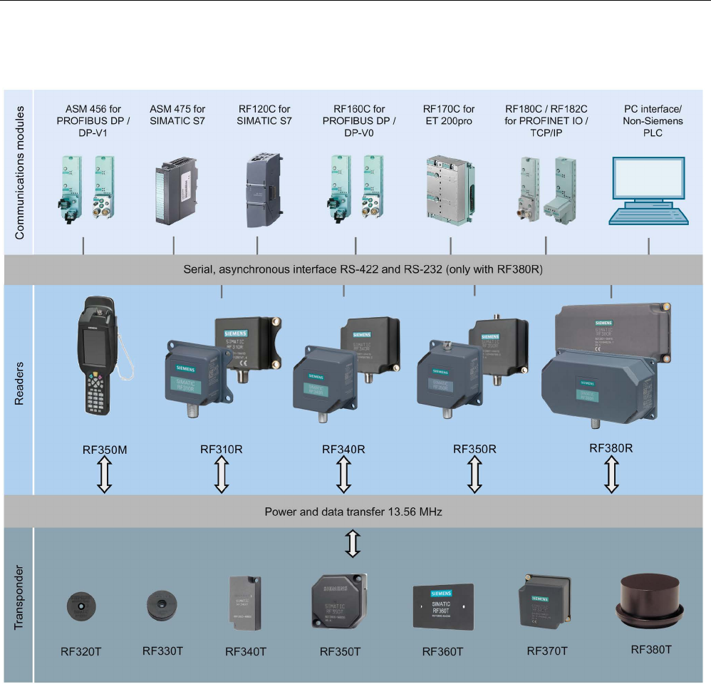
System overview
3.2 SIMATIC RF300
SIMATIC RF300
26 System Manual, 07/2017, C79000-G8976-C345-07
RF300 system components for high-performance applications
Figure 3-1 High performance system overview

System overview
3.2 SIMATIC RF300
SIMATIC RF300
System Manual, 07/2017, C79000-G8976-C345-07 27
Table 3- 4 Reader-transponder combination options for high-performance applications
Transponder
RF310R
RF340R
RF350R
with ANT 1
RF350R
with ANT 3
RF350R
with ANT 18
RF350R
with ANT 30
RF380R
RF320T
✓
✓
✓
✓
✓
✓
✓
RF330T
✓ ✓ ✓ ✓ ✓ ✓ ✓
RF340T
✓
✓
✓
✓
✓
✓
✓
RF350T
✓
✓
✓
--
--
✓
✓
RF360T
✓
✓
✓
--
--
✓
✓
RF370T
✓
1)
✓
✓
--
--
--
✓
RF380T
--
✓
✓
--
--
--
✓
1) as of reader version "AS ≥ D"
✓
Combination possible
--
Combination not possible
○
Combination possible, but not recommended

System overview
3.2 SIMATIC RF300
SIMATIC RF300
28 System Manual, 07/2017, C79000-G8976-C345-07
RF300 system components for medium-performance applications
Figure 3-2 System overview medium-performance

System overview
3.2 SIMATIC RF300
SIMATIC RF300
System Manual, 07/2017, C79000-G8976-C345-07 29
Table 3- 5 Reader-transponder combination options for medium-performance applications
Transponder /
MDS
RF310R
(RS-422)
RF340R
RF350R
with ANT
1
RF350R
with ANT
3
RF350R
with ANT
12
RF350R
with ANT
18
RF350R
with ANT
30
RF380R
MDS D100
✓
✓
✓
--
--
--
○
✓
MDS D117
-- -- -- -- ✓ ✓ -- --
MDS D124
✓
✓
✓
✓
○
✓
✓
✓
MDS D126
✓
✓
✓
--
--
--
✓
✓
MDS D127
--
--
--
--
✓
✓
--
--
MDS D139
✓
✓
✓
--
--
--
○
✓
MDS D160
✓
✓
✓
✓
✓
✓
✓
✓
MDS D165
✓
✓
✓
--
--
--
○
✓
MDS D200
✓
✓
✓
--
--
--
○
✓
MDS D261
✓
✓
✓
--
--
--
○
✓
MDS D324
✓
✓
✓
✓
--
✓
✓
✓
MDS D339
1)
✓
✓
✓
--
--
--
--
✓
MDS D400
✓
✓
✓
--
--
--
--
✓
MDS D421
--
--
--
--
✓
✓
--
--
MDS D422
--
--
--
✓
--
✓
✓
--
MDS D423
✓
✓
✓
✓
--
--
✓
✓
MDS D424
✓
✓
✓
✓
○
✓
✓
✓
MDS D425
✓
✓
✓
✓
○
✓
✓
✓
MDS D426
✓
✓
✓
--
--
--
✓
✓
MDS D428
✓
✓
✓
✓
✓
✓
✓
✓
MDS D460
✓ ✓ ✓ ✓ ✓ ✓ ✓ ✓
MDS D521
--
--
--
--
✓
✓
--
--
MDS D522
--
--
--
--
--
✓
✓
--
MDS D524
✓
✓
✓
--
○
✓
✓
✓
MDS D525
✓
✓
✓
--
○
✓
✓
✓
MDS D526
✓
✓
✓
--
--
--
✓
✓
MDS D528
✓
✓
✓
--
✓
✓
✓
✓
MDS E600
2)
✓
✓
✓
--
--
--
○
✓
MDS E611
2)
✓
✓
✓
--
--
--
○
✓
MDS E623
2)
--
--
--
--
✓
✓
--
--
MDS E624
2)
✓
✓
✓
--
○
✓
✓
✓
1)
as of reader version "AS ≥ D"
2) Product to be discontinued; only relevant for migration projects.
✓
Combination possible
--
Combination not possible
○
Combination possible, but not recommended

System overview
3.2 SIMATIC RF300
SIMATIC RF300
30 System Manual, 07/2017, C79000-G8976-C345-07
Note
Note on operation of the transponders MDS D5xx and MDS E6xx
Note that the transponders MDS D5xx and MDS E6xx can only be operated in conjunction
with the readers of the
second generation (article number "6GT2801-xBAxx").

System overview
3.2 SIMATIC RF300
SIMATIC RF300
System Manual, 07/2017, C79000-G8976-C345-07 31
RF300 system components for Scanmode applications
Figure 3-3 Scanmode system overview

System overview
3.2 SIMATIC RF300
SIMATIC RF300
32 System Manual, 07/2017, C79000-G8976-C345-07
Table 3- 6 Reader-transponder combination options for Scanmode applications
Transponder /
MDS
RF310R
RF380R
RF382R
MDS D100
✓
✓
--
MDS D124
✓ ✓ ✓
MDS D126
✓
✓
--
MDS D139
✓
✓
--
MDS D160
✓
✓
✓
MDS D165
✓
✓
--
MDS D200
✓
✓
--
MDS D261
✓
✓
--
MDS D324
✓
✓
✓
MDS D339
✓
✓
--
MDS D400
✓
✓
--
MDS D423
✓
✓
--
MDS D424
✓
✓
✓
MDS D425
✓
✓
--
MDS D426
✓
✓
--
MDS D428
✓
✓
--
MDS D460
✓
✓
✓
RF320T
✓
✓
--
RF330T
✓
✓
--
RF340T
✓
✓
--
RF350T
✓ ✓ --
RF360T
✓
✓
--
RF370T
--
✓
--
RF380T
--
✓
--
✓
Combination possible
--
Combination not possible
○
Combination possible, but not recommended
Note
Note on operation of the transponders MDS D5xx and MDS E6xx
Note that the transponders MDS D5xx and MDS E6xx can only be operated in conjunction
with the readers of the second generation (article number "6GT2801
-xBAxx").

System overview
3.2 SIMATIC RF300
SIMATIC RF300
System Manual, 07/2017, C79000-G8976-C345-07 33
3.2.3
Application areas of RF300
SIMATIC RF300 is primarily used for non-contact identification of containers, palettes and
workpiece holders in a closed production circuit. The data carriers (transponders) remain in
the production chain and are not supplied with the products. SIMATIC RF300, with its
compact transponder and reader enclosure dimensions, is particularly suitable in confined
spaces.
Main applications
● Mechanical engineering, automation systems, conveyor systems
● Ancillary assembly lines in the automotive industry, component suppliers
● Small assembly lines
Application examples
● Production lines for engines, gearboxes, axles, etc.
● Assembly lines for ABS systems, airbags, brake systems, doors, cockpits, etc.
● Assembly lines for household electrical appliances, consumer electronics and electronic
communication equipment
● Assembly lines for PCs, small-power motors, contactors, switches
Advantages
● Reading and writing of large data volumes within a short time results in shorter production
cycle times and helps to boost productivity
● Can be used in harsh environments thanks to rugged components with high degree of
protection
● Simple system integration into TCP/IP networks, SIMATIC S7, PROFINET and
PROFIBUS (TIA) with little effort
● Shorter commissioning times and fewer plant failures and downtimes thanks to integral
diagnostic functionalities
● Cost savings thanks to maintenance-free components

System overview
3.3 System configuration
SIMATIC RF300
34 System Manual, 07/2017, C79000-G8976-C345-07
3.3
System configuration
3.3.1
Overview
The SIMATIC RF300 system is characterized by a high level of standardization of its
components. This means that the system follows the TIA principle throughout: Totally
Integrated Automation. It provides maximum transparency at all levels with its reduced
interface overhead. This ensures optimum interaction between all system components.
The RF300 system with its flexible components offers many possibilities for system
configuration. This chapter shows you how you can use the RF300 components on the basis
of various example scenarios.
3.3.2
Assembly line example: Use of RF300 transponders
In assembly lines, such as in engine manufacturing, many work steps are completed in
succession. Automated or manual assembly work is carried out at the individual workstations
in relatively short periods of time. The special features of the RF300 transponders, which
stand out for their large data memory and high transmission speeds, bring about many
advantages in regard to the production unit numbers of such plants.
The possibility of saving large volumes of data means savings in terms of data management
on the HOST system and considerably contributes to data security (redundant data
management e.g. HOST database or controller and data carrier)
Advantages at a glance:
● redundant data storage on the basis of large memory, availability of decentralized data
● high data rate
● data management savings on the host system
Features of the scenario
In this example scenario, engine blocks that are placed on metal pallets are conveyed on an
assembly line. The engines are assembled piece-by-piece at the individual workstations. The
RFID transponder of the type SIMATIC RF340T is mounted permanently on the underside of
the pallet. The transport speed is approx. 0.5 m/s.
In this scenario, it is an advantage that the transponder can be directly secured to metal on
the metal pallets. The small-dimensioned SIMATIC RF310R reader is integrated in the
conveyor elements in such a manner that it can communicate with the transponders from
below. Thus, it is not necessary to align the pallets or to attach several transponders.
The data of the entire production order (5000 bytes) is stored on the transponder. This data
is read at each workstation and changed or supplemented depending on the workstation,
and then written back again. Thus, the status of the engine block assembly can be
determined at any point in time, even if there is a failure at the HOST level.
Thanks to the extremely high data rate, a very short cycle time for the work steps can be
planned, which results in high end product unit numbers "engines".
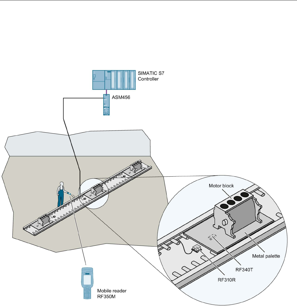
System overview
3.3 System configuration
SIMATIC RF300
System Manual, 07/2017, C79000-G8976-C345-07 35
The entire production order that is saved on the transponder can also be read manually via
the WIN-LC terminal located at each workstation. This means that virtually no additional data
management is required on the control computer.
The production order data can also be read for servicing purposes via the mobile SIMATIC
RF350M reader.
Figure 3-4 Example of engine block production

System overview
3.3 System configuration
SIMATIC RF300
36 System Manual, 07/2017, C79000-G8976-C345-07
3.3.3
Example of container and cardboard container handling: Use of ISO
transponders
Containers of varying sizes are conveyed to picking workstations in a delivery center. There,
the individual goods are removed and packed in cartons according to the delivery note.
These cartons are marked with low-cost transponder labels and sorted to small or large
packaging workstations (according to the delivery note) by being guided or transported via
the corresponding conveyor system. The containers are marked using the MDS D100 ISO
transponder.
Advantages at a glance:
● Decision points in the conveyor system can be installed in a more favorable way
(mechanically)
● Different sizes of containers with different depths can be identified due to the range
● In contrast to bar codes, the transponders can also be written to
● Different types of transponders can be processed using one and the same reader
Features of the scenario
In this example scenario, containers of varying sizes are conveyed on a conveyor system.
Only the unique identification number (8 bytes) is read. The containers to be picked are
sorted to the corresponding workstations. The maximum transport speed is 1.0 m/s.
In this scenario, it is an advantage that the RF380R reader can read and write the
transponders at different distances on the containers without a great deal of mechanical or
control system effort due to the reading range.
During the picking process, the goods are immediately placed in different containers or
packed in cartons depending on the destination (small packaging or large packaging station).
The containers are equipped with the MDS D100 ISO transponder. The low-cost "one-way
tag" (label) is used on the cartons: it is simply glued onto the carton. Thus the goods can be
identified at any time. Again, one and the same reader hardware is used for this. The
maximum transport speed is 0.8 m/s.
In addition, flexible identification is possible at each location and at any time using the mobile
SIMATIC RF350M reader.
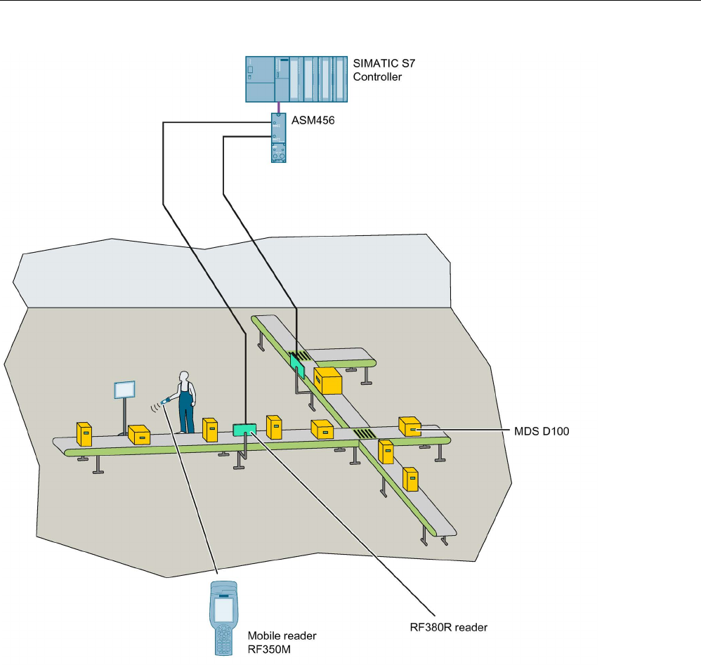
System overview
3.3 System configuration
SIMATIC RF300
System Manual, 07/2017, C79000-G8976-C345-07 37
Figure 3-5 Example of container and cardboard container handling

System overview
3.3 System configuration
SIMATIC RF300
38 System Manual, 07/2017, C79000-G8976-C345-07
SIMATIC RF300
System Manual, 07/2017, C79000-G8976-C345-07 39
Planning the RF300 system
4
4.1
Fundamentals of application planning
4.1.1
Selection criteria for SIMATIC RF300 components
Assess your application according to the following criteria, in order to choose the right
SIMATIC RF300 components:
● Transmission distance (read/write distance)
● Tracking tolerances
● Static or dynamic data transfer
● Data volume to be transferred
● Speed in case of dynamic transfer
● Metal-free rooms for transponders and readers
● Ambient conditions such as relative humidity, temperature, chemical impacts, etc.
4.1.2
Transmission window and read/write distance
The reader generates an inductive alternating field. The field is strongest close to the reader;
however, a read/write distance of "zero" between reader and transponder is not
recommended.
The field strength of the alternating field decreases strongly the further away from the reader.
The distribution of the antenna field depends on the structure and geometry of the antennas
in the reader and transponder.
For the transponder to function correctly, a minimum field strength at the transponder must
be achieved at a distance Sg from the reader or the antenna.
The figures below show the transmission window between transponder and reader or
between transponder and antenna:
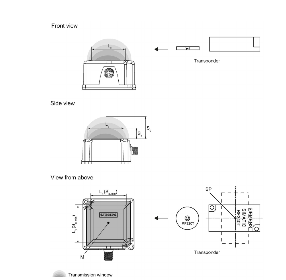
Planning the RF300 system
4.1 Fundamentals of application planning
SIMATIC RF300
40 System Manual, 07/2017, C79000-G8976-C345-07
Sa
Operating distance between transponder and reader
Sg Limit distance (maximum clear distance between upper surface of the reader and the tran-
sponder, at which the transmission can still just function under normal conditions)
Lx Length of a transmission window in the x direction while maintaining the working distance (Lx ≠
Ly with RF380R and RF382R)
Ly Length of a transmission window in the y direction while maintaining the working distance (Lx ≠
Ly with RF380R and RF382R)
M
Field centerpoint
SP
Intersection of the axes of symmetry of the transponder
Figure 4-1 Transmission window and read/write distance reader
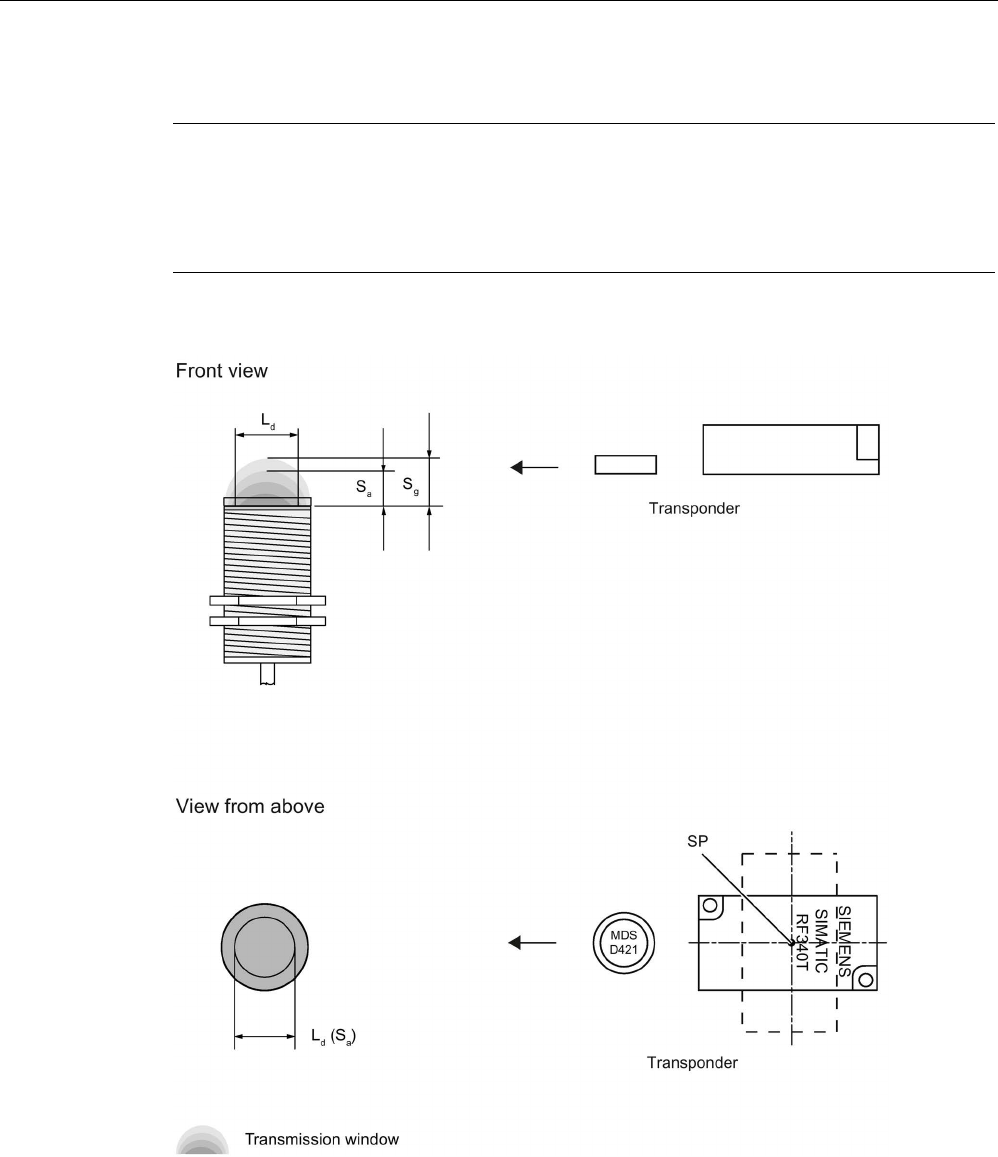
Planning the RF300 system
4.1 Fundamentals of application planning
SIMATIC RF300
System Manual, 07/2017, C79000-G8976-C345-07 41
Note
Transmission window with RF380R and RF382R
Note that the transmission window of the reader RF380R is not square (L
x ≠ Ly). To obtain
as
large a transmission window as possible, make sure that the transponder only crosses the
reader in the x direction.
Sa
Operating distance between transponder and reader
Sg Limit distance (maximum clear distance between upper surface of the reader and the tran-
sponder, at which the transmission can still just function under normal conditions)
Ld
Diameter of a transmission window
SP
Intersection of the axes of symmetry of the transponder
Figure 4-2 Transmission window and read/write distance round antenna

Planning the RF300 system
4.1 Fundamentals of application planning
SIMATIC RF300
42 System Manual, 07/2017, C79000-G8976-C345-07
The transponder can be used as soon as the intersection (SP) of the transponder enters the
area of the transmission window.
From the diagrams above, it can also be seen that operation is possible within the area
between Sa and Sg. The active operating area reduces as the distance increases, and
shrinks to a single point at distance Sg. Only static mode should thus be used in the area
between Sa and Sg.
Aids for calculating the field data
Note
Determining the operating distance, limit distance and transmission window
Remember that you can obtain
the values Sa, Sg and L simply and quickly using the tool for
field data acquisition. You will find this on the DVD "Ident Systems, Software &
Documentation".
4.1.3
Width of the transmission window
Determining the width of the transmission window
The following approximation formula can be used for practical applications:
B:
Width of the transmission window
L:
Length of the transmission window
Tracking tolerances
The width of the transmission window (B) is particularly important for the mechanical tracking
tolerance. The formula for the dwell time is valid without restriction when B is observed.
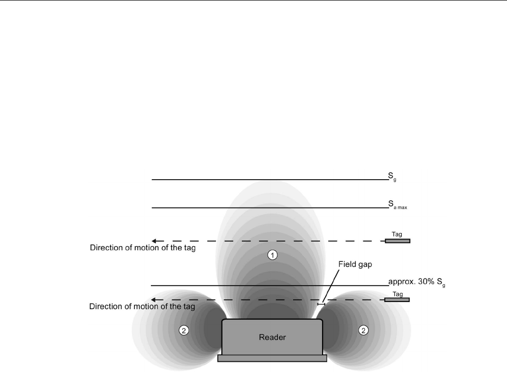
Planning the RF300 system
4.1 Fundamentals of application planning
SIMATIC RF300
System Manual, 07/2017, C79000-G8976-C345-07 43
4.1.4
Impact of secondary fields
Secondary fields in the range from 0 mm to 30% of the limit distance (Sg) generally always
exist.
They should, however, only be used during configuration in exceptional cases, since the
read/write distances are very limited. Exact details of the secondary field geometry cannot be
given, since these values depend heavily on the operating distance and the application.
When working in dynamic mode, remember that during the transition from the secondary
field to the main field the presence of the tag is lost temporarily. It is therefore advisable to
select a distance > 30 % of Sg.
①
Main field
②
Secondary field
Figure 4-3 Gap in the field resulting from secondary fields
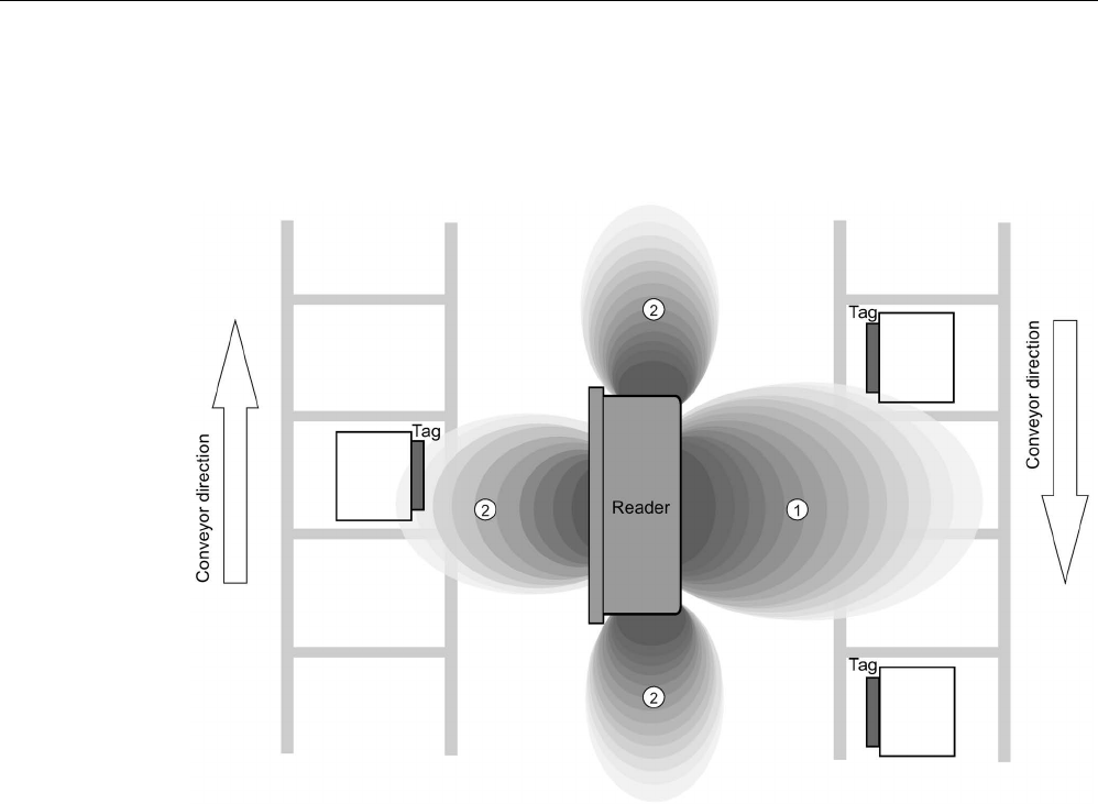
Planning the RF300 system
4.1 Fundamentals of application planning
SIMATIC RF300
44 System Manual, 07/2017, C79000-G8976-C345-07
Secondary fields without shielding
The following graphic shows typical primary and secondary fields, if no shielding measures
are taken.
①
Main field
②
Secondary field
Figure 4-4 Secondary field without shielding
In this arrangement, the reader can also read tags via the secondary field. Shielding is
required in order to prevent unwanted reading via the secondary field, as shown and
described in the following.
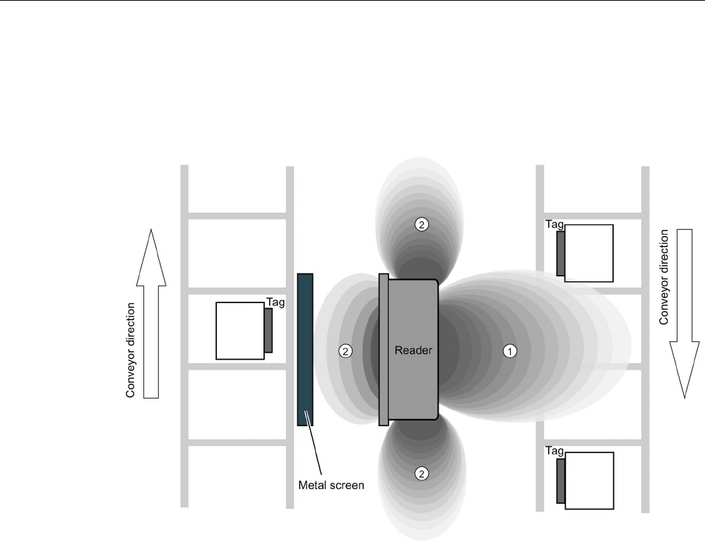
Planning the RF300 system
4.1 Fundamentals of application planning
SIMATIC RF300
System Manual, 07/2017, C79000-G8976-C345-07 45
Secondary fields with shielding
The following graphic shows typical primary and secondary fields, with metal shielding this
time.
The metal shielding prevents the reader from detecting tags via the secondary field.
①
Main field
②
Secondary field
Figure 4-5 Secondary field with shielding

Planning the RF300 system
4.1 Fundamentals of application planning
SIMATIC RF300
46 System Manual, 07/2017, C79000-G8976-C345-07
4.1.5
Setup help of the readers of the second generation
After turning on the reader (connection to the power supply) and the following startup phase,
the reader automatically changes to the "Setup" mode. During this the antenna (reader-
internal or external) is turned on, in contrast to generation 1 in which the antenna is turned
on by a RESET.
In this status "search for transponders" the reader scans the antenna field for transponders
with all air interface protocols (RF300, ISO 15693, ISO 14443). If a transponder is
recognized in the antenna field of the reader only the HF protocol of the recognized
transponder type is used and there is a change in the status to "Show quality". In this status
you obtain direct feedback about the quality of the communication with the transponder via
the LED. Depending on the environment (metal, interference) or the field coupling with the
transponder (size of the transponder antenna) as well as the individual field geometry (shape
of the main and side lobe) of the reader, communication can be very good (permanent light)
or good (flickering) at certain locations in the antenna field. These factors give users the
option of finding the optimal area in the specific installation situation or in a combination. If no
transponder is recognized for a longer period of time, the reader changes back to the
"Search for transponders" status.
When a "RESET" command is received, the reader changes back to the normal operation as
known from the RF300.
Meaning of the LED operating display in the "Setup" mode
The operational statuses of the reader are displayed by two LEDs. The LEDs can adopt the
colors white green, red, yellow or blue and the statuses off , on , flashing .
Table 4- 1 Display elements
LED
Meaning
The reader is turned off.
The reader is turned on and is searching for transponders.
The reader is in the "Setup" mode, in the "Search for transponders" status and
has not yet received a "RESET" command and is not ready.
/ There is transponder in the antenna field.
The reader is in the "Setup" mode, in the status "Show quality", has not yet re-
ceived a "RESET" command and is not ready.
Depending on the quality of the communication, the LED flickers or is lit perma-
nently.
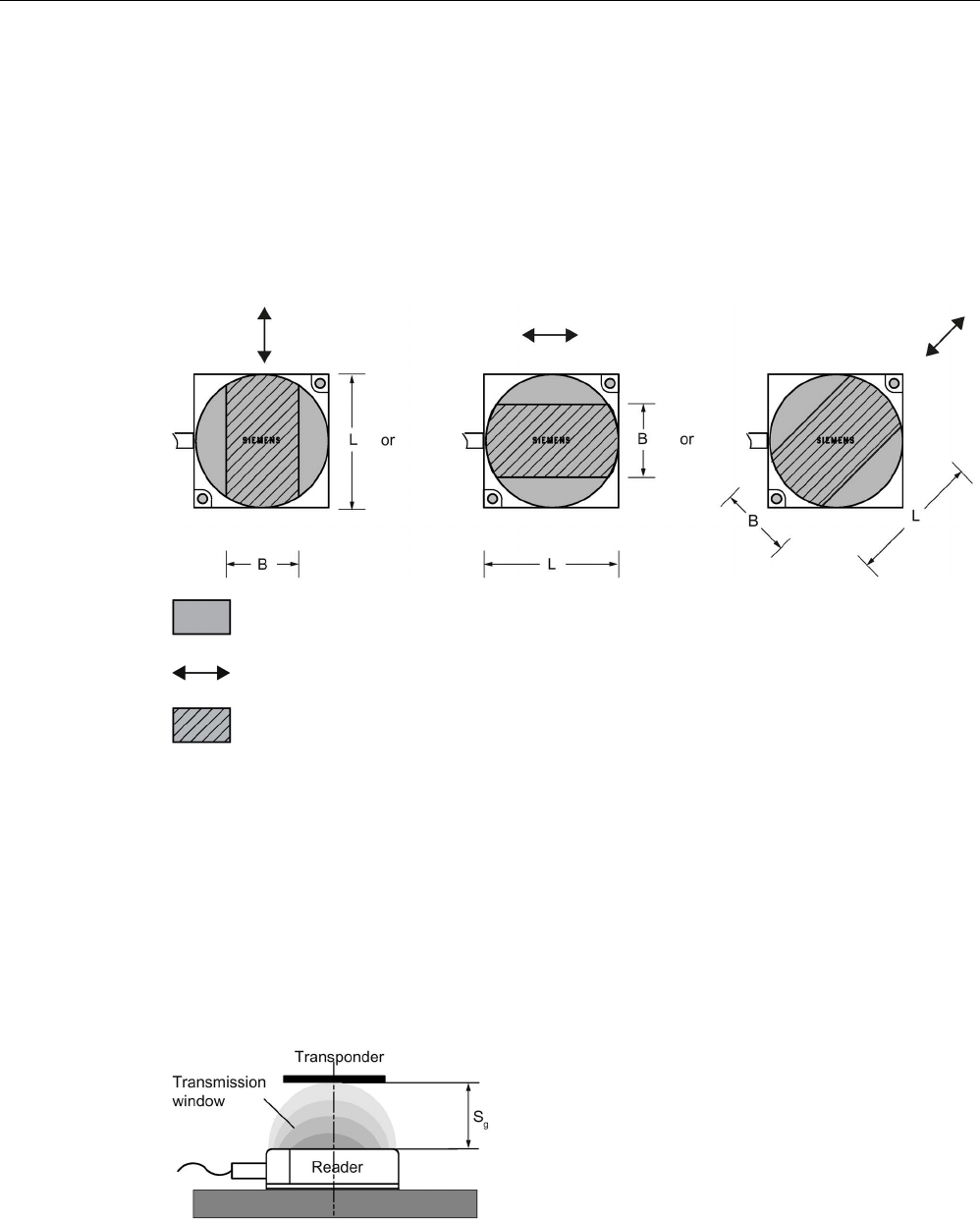
Planning the RF300 system
4.1 Fundamentals of application planning
SIMATIC RF300
System Manual, 07/2017, C79000-G8976-C345-07 47
4.1.6
Permissible directions of motion of the transponder
Detection area and direction of motion of the transponder
The transponder and reader have no polarization axis, i.e. the transponder can come in from
any direction, assume any position as parallel as possible to the reader, and cross the
transmission window. The figure below shows the active area for various directions of
transponder motion:
Transmission window
Direction of motion of the transponder
Detection area L x W
Figure 4-6 Detection areas of the reader for different directions of transponder motion
4.1.7
Operation in static and dynamic mode
Operation in static mode
If working in static mode, the transponder can be operated up to the limit distance (Sg). The
transponder must then be positioned exactly over the reader:
Figure 4-7 Operation in static mode
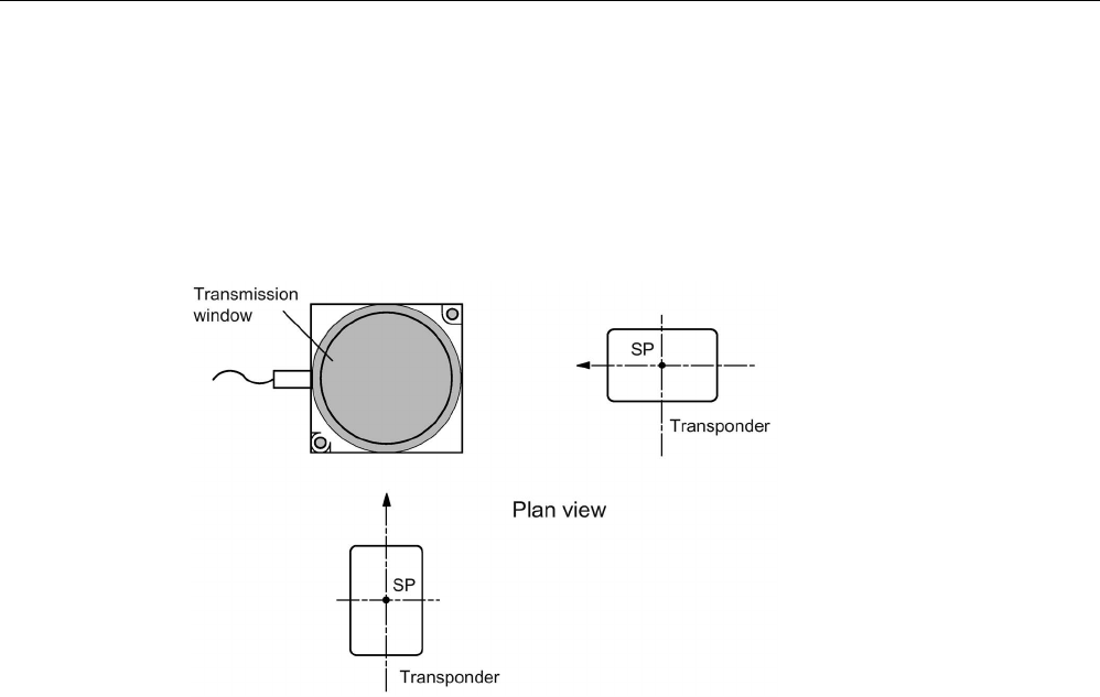
Planning the RF300 system
4.1 Fundamentals of application planning
SIMATIC RF300
48 System Manual, 07/2017, C79000-G8976-C345-07
Operation in dynamic mode
When working in dynamic mode, the transponder moves past the reader. The transponder
can be used as soon as the intersection (SP) of the transponder enters the circle of the
transmission window. In dynamic mode, the operating distance (Sa) is of primary importance.
[Operating distances, see Chapter Field data for transponders, readers and antennas
(Page 51)]
Figure 4-8 Operation in dynamic mode
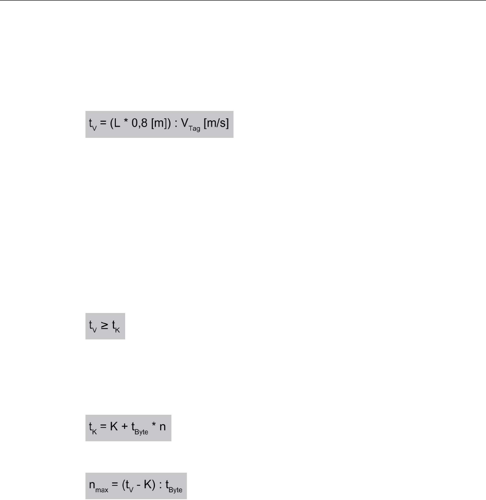
Planning the RF300 system
4.1 Fundamentals of application planning
SIMATIC RF300
System Manual, 07/2017, C79000-G8976-C345-07 49
4.1.8
Dwell time of the transponder
The dwell time is the time in which the transponder remains within the transmission window
of the reader. The reader can exchange data with the transponder during this time.
The dwell time is calculated as follows:
t
V
:
Dwell time of the transponder
L:
Length of the transmission window
v
Tag
:
Speed of the transponder (tag) in dynamic mode
0.8:
Constant factor used to compensate for temperature influence
and production toler-
ances
The dwell time can be of any duration in static mode. The dwell time must be sufficiently long
to allow communication with the transponder.
The dwell time is defined by the system environment in dynamic mode. The volume of data
to be transferred must be matched to the dwell time or vice versa. As a general rule:
t
V:
:
Dwell time of the data memory in the field of the reader
t
K
:
Communication time between transponder and communication module
or Calculation of the maximum amount of user data
t
K
:
Communication time between transponder and communication module
K
Constant; the constant is an internal system time. This includes the time for power
buildup on the MDS and for command transfer
tByte
Transmission time for 1 byte
n
Amount of user data in bytes
n
max
Maximum amount of user data in bytes in dynamic mode
t
V
Dwell time of the data memory in the field of the reader
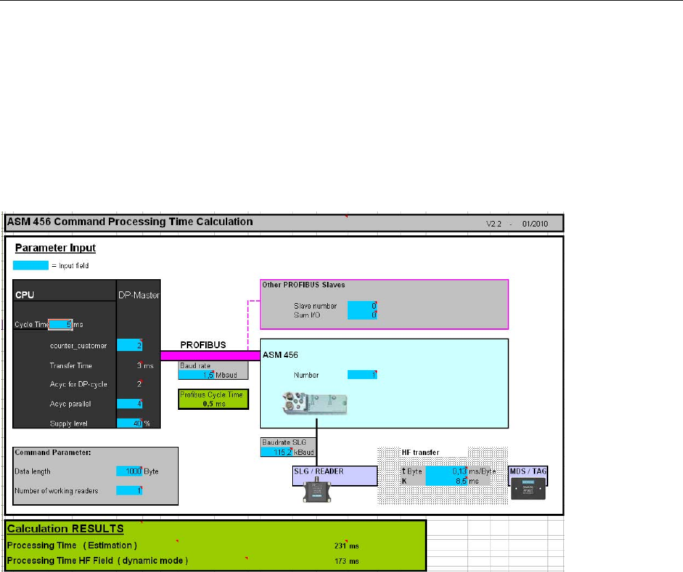
Planning the RF300 system
4.1 Fundamentals of application planning
SIMATIC RF300
50 System Manual, 07/2017, C79000-G8976-C345-07
4.1.9
Communication between communications module, reader and transponder
Aids for calculating the data transmission times
User-friendly calculation tools are available for the communications modules ASM 456,
RF160C, RF170C and RF180C to calculate data transfer times. The calculation tools can be
found on the DVD "Ident Systems Software & Documentation", article number 6GT2080-
2AA20.
Figure 4-9 User interface of the calculation tool for command processing time
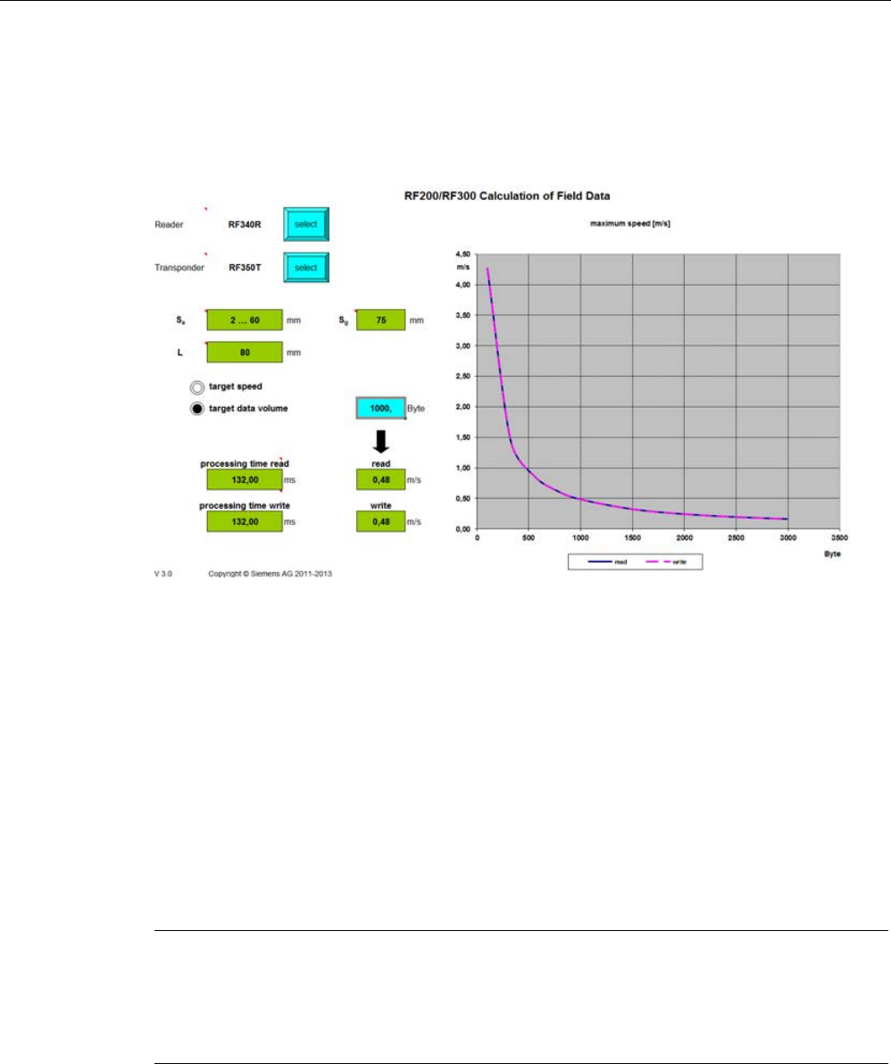
Planning the RF300 system
4.2 Field data for transponders, readers and antennas
SIMATIC RF300
System Manual, 07/2017, C79000-G8976-C345-07 51
Aids for calculating the field data
You will also find a tool for calculating field data on the DVD "Ident Systems, Software &
Documentation". Using this tool, among other things you can calculate the operating
distance (Sa), limit distance (Sg) and transmission window (L).
Figure 4-10 User interface of the calculation tool for field data acquisition
4.2
Field data for transponders, readers and antennas
The following tables show the field data for all SIMATIC RF300 components of transponders
and readers. This makes the correct selection of a transponder and reader particularly easy.
All the technical specifications listed are typical data and are applicable for an ambient
temperature between 0 °C and +50 °C, a supply voltage between 22 and 27 VDC and a
metal-free environment.
Tolerances of ±20 % are permitted due to production or temperature
conditions.
If the entire voltage range at the reader of 20 VDC to 30 VDC and/or the entire temperature
range of transponders and readers is used, the field data is subject to further tolerances.
Note
Transmission gaps
If the minimum operating distance (S
a) is not observed, a transmission gap can occur in the
center of the field. Communication with the transponder is not possible in the transmission
gap, see section "
Impact of secondary fields (Page 43)".

Planning the RF300 system
4.2 Field data for transponders, readers and antennas
SIMATIC RF300
52 System Manual, 07/2017, C79000-G8976-C345-07
Note
Possible reader-transponder combinations
The tables of the following section show the possible reader
-transponder combinations.
4.2.1
Field data of RF300 transponders
The limit distances (Sg) and operating distances (Sa) along with the length of the
transmission window for each reader-transponder combination are listed in the tables below.
In dynamic mode, make sure that rectangular transponders cross the antenna field in the
longitudinal direction.
Table 4- 2 Field data RF310R reader
Length of the transmission
window (L)
Operating distance (Sa)
Limit distance (Sg)
RF320T
30
1...23
26
RF330T
30
2...18
21
RF340T
40 2...36 41
RF350T
45
2...47
53
RF360T
45
2...60
68
RF370T
70
2...45
60
All values are in mm
The values relate to the RF310R reader as of version "D".
Table 4- 3 Field data RF340R reader
Length of the transmission
window (L)
Operating distance (Sa)
Limit distance (Sg)
RF320T
45
1...20
25
RF330T
40
2...18
23
RF340T
80
2...50
58
RF350T
80
2...60
75
RF360T
90
2...65
85
RF370T
85
5...60
80
RF380T
90
5...80
100
All values are in mm

Planning the RF300 system
4.2 Field data for transponders, readers and antennas
SIMATIC RF300
System Manual, 07/2017, C79000-G8976-C345-07 53
Table 4- 4 Field data RF350R reader / ANT 1
Length of the transmission
window (L)
Operating distance (Sa)
Limit distance (Sg)
RF320T
45
1...30
37
RF330T
40 1...25 30
RF340T
80
2...55
70
RF350T
80
2...65
85
RF360T
90
2...75
100
RF370T
85
5...65
85
RF380T
90
5...90
110
All values are in mm
Table 4- 5 Field data RF350R reader / ANT 3
Length of the transmission
window (L)
Operating distance (Sa)
Limit distance (Sg)
RF320T
25
1...15
18
RF330T
25
1...10
15
RF340T
40
2...25
30
All values are in mm
Table 4- 6 Field data RF350R reader / ANT 18
Diameter of the transmis-
sion window (Ld)
Operating distance (Sa)
Limit distance (Sg)
RF320T
10
0...10
13
RF330T
10
0...11
13
RF340T
20
0...18
22
All values are in mm
Table 4- 7 Field data RF350R reader / ANT 30
Diameter of the transmis-
sion window (Ld)
Operating distance (Sa)
Limit distance (Sg)
RF320T
15
0...15
20
RF330T
22
0...15
18
RF340T
35
0...25
30
RF350T
35
0...35
40
RF360T
80 2...32 38
All values are in mm

Planning the RF300 system
4.2 Field data for transponders, readers and antennas
SIMATIC RF300
54 System Manual, 07/2017, C79000-G8976-C345-07
Table 4- 8 Field data RF380R reader
Length of the transmission window
Operating distance
(Sa)
Limit distance (Sg)
in the x direction (Lx)
in the y direction (Ly)
RF320T
100
40
2...45
60
RF330T
120
30
5...45
52
RF340T
120 50 2...80 105
RF350T
140
60
2...100
125
RF360T
160
70
2...120
150
RF370T
160
65
5...100
135
RF380T
180
75
5...125
160
All values are in mm
RF380R reader: Setting the transmit power
The RF380R reader (6GT2801-3AB10) allows the transmission output power to be set with
the aid of the "distance_limiting" input parameter (you will find more detailed information in
the document "Input parameters for the RF300 system for programming via communications
modules"). For this, values from 0.5 W to 2.0 W can be set in 0.25 W increments. When
doing this, remember that the change to the transmit power will affect the detection in the
limit range (upper/ lower operating distance), as well as the minimum distance that is to be
maintained between adjacent RF380Rs. A higher working version is not to be expected.
Table 4- 9 Adjustable transmit power of the RF380R reader with the aid of the "distance_limiting"
parameter
Value
Transmit power
02
0.5 W
03
0.75 W
04
1.0 W
05
1.25 W (default)
06
1.5 W
07
1.75 W
08
2.0 W

Planning the RF300 system
4.2 Field data for transponders, readers and antennas
SIMATIC RF300
System Manual, 07/2017, C79000-G8976-C345-07 55
Note
Setting outside the range
Settings outside the specified range (02 ... 08) have the effect that the default value (1.25
W)
is set. In this case for reasons of compatibility there is no error message.
This setting is not necessary with the RF380R readers of the 2nd generation (6GT
2801-
3BAx0) because the power limits are optimized automatically depending on the reader
-
transponder distance. For reasons of compatibility this setting can nevertheless be made.
Note that the values "02", "03" and "04" bring about a reduction of the power
of
approximately 50%.
You will find more information on this subject in the chapter "
Minimum clearances (Page 64
)"
section "Minimum distance from
reader to reader".
See also
Product Information "Input parameters for the RF300 system for programming via
communications modules" (https://support.industry.siemens.com/cs/ww/en/ps/15033/man)

Planning the RF300 system
4.2 Field data for transponders, readers and antennas
SIMATIC RF300
56 System Manual, 07/2017, C79000-G8976-C345-07
4.2.2
Field data of ISO transponders (MDS D)
The limit distances (Sg) and operating distances (Sa) along with the length of the
transmission window for each reader-transponder combination are listed in the tables below.
Observe the following information for field data of ISO transponders:
● A maximum median deviation of ±2 mm is permitted in static mode (without affecting the
field data).
● In dynamic mode, make sure that rectangular transponders cross the antenna field in the
longitudinal direction.
Table 4- 10 Field data RF310R reader
Length of the transmission
window (L)
Operating distance (Sa)
Limit distance (Sg)
MDS D100
40
2...93
105
MDS D124
30 2...64 72
MDS D126
90
2...65
73
MDS D139
105 5...96 109
MDS D160
30
2...39
44
MDS D165
130
2...90
102
MDS D200
120
2...80
90
MDS D261
80
2...74
83
MDS D324
30
2...47
63
MDS D339
85
5...74
84
MDS D400
90
2...104
115
MDS D423
55
2...35
40
MDS D424
35
1...68
75
MDS D425
30
1...22
25
MDS D426
90
5...75
90
MDS D428
30
1...40
45
MDS D460
30
1...32
38
MDS D524
35
1...70
78
MDS D525
30
1...22
25
MDS D526
90
5...80
90
MDS D528
30 1...43 48
All values are in mm

Planning the RF300 system
4.2 Field data for transponders, readers and antennas
SIMATIC RF300
System Manual, 07/2017, C79000-G8976-C345-07 57
Table 4- 11 Field data RF340R reader
Length of the transmission
window (L)
Operating distance (Sa)
Limit distance (Sg)
MDS D100
90
5...110
140
MDS D124
60 2...60 75
MDS D126
80
2...85
110
MDS D139
90
5...80
110
MDS D160
50
2...35
60
MDS D165
130
15...120
140
MDS D200
125
10...100
1)
115
MDS D261
95
15...60
2)
70
MDS D324
50
2...55
70
MDS D339
100
5...75
85
MDS D400
140
2...100
130
MDS D423
65
5...40
48
MDS D424
50
2...55
70
MDS D425
45
2...20
30
MDS D426
110
0...80
100
MDS D428
45
2...40
50
MDS D460
45
2...25
40
MDS D524
50
2...55
70
MDS D525
45
2...20
30
MDS D526
110
0...80
100
MDS D528
45 2...40 50
1)
When operating the reader of the second generation and an ambient temperature > 50 °C, the
operating distance (Sa) is 15 ... 80 mm.
2)
When operating the reader of the second generation the operating distance (Sa) is 40 ... 100 mm
and the limit distance .(Sg) is 150 mm.
All values are in mm

Planning the RF300 system
4.2 Field data for transponders, readers and antennas
SIMATIC RF300
58 System Manual, 07/2017, C79000-G8976-C345-07
Table 4- 12 Field data RF350R reader / ANT 1
Length of the transmission
window (L)
Operating distance (Sa)
Limit distance (Sg)
MDS D100
80
5...110
140
MDS D124
55 2...65 85
MDS D126
150
2...90
120
MDS D139
75
5...85
115
MDS D160
50
2...35
60
MDS D165
140
5...100
120
MDS D200
130
5...95
115
MDS D261
100
5...80
95
MDS D324
50
2...66
78
MDS D339
110
5...90
105
MDS D400
140
2...110
135
MDS D423
85
10...40
50
MDS D424
50
2...75
88
MDS D425
40
2...25
35
MDS D426
110
2...85
95
MDS D428
40
2...40
50
MDS D460
40
2...32
38
MDS D524
50
2...65
85
MDS D525
40
2...25
35
MDS D526
110
2...85
105
MDS D528
40 2...35 50
All values are in mm
Table 4- 13 Field data RF350R reader / ANT 3
Diameter of the transmis-
sion window (Ld)
Operating distance (Sa)
Limit distance (Sg)
MDS D124
40
1...35
42
MDS D160
40
1...28
35
MDS D324
40 1...22 32
MDS D422
20
1...11
18
MDS D423
30
5...20
30
MDS D424
40
1...40
48
MDS D425
25
2...18
22
MDS D428
30
2...28
30
MDS D460
30
1...20
28
All values are in mm

Planning the RF300 system
4.2 Field data for transponders, readers and antennas
SIMATIC RF300
System Manual, 07/2017, C79000-G8976-C345-07 59
Table 4- 14 Field data RF350R reader / ANT 12
Diameter of the transmis-
sion window (Ld)
Operating distance (Sa)
Limit distance (Sg)
MDS D117
2
0...2
3
MDS D127
2 0...3 4
MDS D160
15
0...8
12
MDS D421
6
0...3
5
MDS D428
15
1...10
17
MDS D460
8
1...8
10
MDS D521
6
0...3
5
MDS D528
15
1...10
17
All values are in mm
Table 4- 15 Field data RF350R reader / ANT 18
Diameter of the transmis-
sion window (Ld)
Operating distance (Sa)
Limit distance (Sg)
MDS D117
3
0...5
6
MDS D124
27
2...24
28
MDS D127
3
0...5
6
MDS D160
20
1...18
20
MDS D324
25
1...22
28
MDS D421
10
0...6
8
MDS D422
20
1...10
13
MDS D424
25
1...27
35
MDS D425
17
1...10
14
MDS D428
17
1...15
20
MDS D460
15
1...12
16
MDS D521
10
0...6
8
MDS D522
20
1...10
13
MDS D524
25
1...27
35
MDS D525
17
1...10
14
MDS D528
17 1...15 20
All values are in mm

Planning the RF300 system
4.2 Field data for transponders, readers and antennas
SIMATIC RF300
60 System Manual, 07/2017, C79000-G8976-C345-07
Table 4- 16 Field data RF350R reader / ANT 30
Diameter of the transmis-
sion window (Ld)
Operating distance (Sa)
Limit distance (Sg)
MDS D124
30
1...35
40
MDS D126
70 0...42 50
MDS D160
25
1...24
28
MDS D324
30
1...35
40
MDS D422
30
0...14
16
MDS D423
45
5...22
28
MDS D424
28
0...45
50
MDS D425
25
1...15
20
MDS D426
65
0...45
48
MDS D428
25
1...25
28
MDS D460
22
1...18
20
MDS D522
30
0...15
19
MDS D524
28
0...45
50
MDS D525
25
1...15
20
MDS D526
65
0...45
48
MDS D528
25
1...25
28
All values are in mm
Table 4- 17 Field data RF380R reader
Length of the transmission window
Operating distance
(Sa)
Limit distance (Sg)
in the x direction (Lx)
in the y direction (Ly)
MDS
D100
1)
140 100 10...170 210
MDS D124
80
80
1...120
140
MDS D126
180
140
2...145
190
MDS D139
140
90
5...160
200
MDS D160
80
40
2...64
80
MDS D165
1)
200 140 10...170 200
MDS
D200
2)
200 160 20...150 195
MDS
D261
3)
190 120 20..120 160
MDS D324
100
60
2...96
120
MDS D339
290
140
5...160
180
MDS D400
240
120
10...200
240
MDS D423
110
60
5...75
90
MDS D424
100
70
2...120
140
MDS D425
80
45
2...35
50

Planning the RF300 system
4.2 Field data for transponders, readers and antennas
SIMATIC RF300
System Manual, 07/2017, C79000-G8976-C345-07 61
Length of the transmission window
Operating distance
(Sa)
Limit distance (Sg)
in the x direction (Lx)
in the y direction (Ly)
MDS D426
220
160
0...155
195
MDS D428
80
50
2…70
95
MDS D460
80 70 2…65 90
MDS D524
100
70
2...120
140
MDS D525
80
45
2...35
50
MDS D526
220
160
0...155
195
MDS D528
80
50
2…70
95
All values are in mm
1)
Keep in mind that the minimum distance must be increased by 10 mm with ambient temperatures
of 40 °C and higher.
2)
Keep in mind that the minimum distance of the reader to the transponder must be increased by
7 mm (1st generation) or 6 mm (2nd generation) for every 5 °C rise in temperature with ambient
temperatures of 25 °C and higher. The minimum distance must be increased by 15 mm with ambi-
ent temperatures of 50 °C and higher (1st and 2nd generation).
3)
Keep in mind that the minimum distance of the reader to the transponder must be increased by
5 mm (1st generation) or 3 mm (2nd generation) for every 5 °C rise in temperature with ambient
temperatures of 25 °C and higher. The minimum distance must be increased by 9 mm (1st genera-
tion) or 14 mm (2nd generation) with ambient temperatures of 50 °C and higher.
Table 4- 18 Field data RF382R reader
Length of the transmission window
Operating distance
(Sa)
Limit distance (Sg)
in the x direction (Lx)
in the y direction
(Ly)
MDS D124
70
130
40...65
75
MDS D160
50
100
35...50
65
MDS D324
60
120
40...65
75
MDS D424
65
120
40...65
75
MDS D460
40
80
30...50
60
All values are in mm
4.2.3
Field data of ISO transponders (MDS E)
The limit distances (Sg) and operating distances (Sa) along with the length of the
transmission window for each reader-transponder combination are listed in the tables below.
Observe the following information for field data of ISO transponders:
● A maximum median deviation of ±2 mm is possible in static mode (without affecting the
field data).
● In dynamic mode, make sure that rectangular transponders cross the antenna field in the
longitudinal direction.

Planning the RF300 system
4.2 Field data for transponders, readers and antennas
SIMATIC RF300
62 System Manual, 07/2017, C79000-G8976-C345-07
Note
Relenace of the MDS E transponders
The MDS E transponders are products that will be discontinued. These are relevant for
migration proje
cts in which existing RFID systems are replaced by SIMATIC RF300,
generation 2.
Note that the MDS E transponders can only be operated in conjunction with the readers of
the second generation!
Table 4- 19 Field data RF310R reader
Length of the transmission
window (L)
Operating distance (Sa)
Limit distance (Sg)
MDS E600
80
2...30
43
MDS E611
80
2...40
60
MDS E624
45
2...25
36
All values are in mm
Table 4- 20 Field data RF340R reader
Length of the transmission
window (L)
Operating distance (Sa)
Limit distance (Sg)
MDS E600
90
5...50
65
MDS E611
90
10...50
65
MDS E624
60
2...35
45
All values are in mm
Table 4- 21 Field data RF350R reader / ANT 1
Length of the transmission
window (L)
Operating distance (Sa)
Limit distance (Sg)
MDS E600
70
10...50
60
MDS E611
100
10...50
65
MDS E624
55
2...35
45
All values are in mm

Planning the RF300 system
4.2 Field data for transponders, readers and antennas
SIMATIC RF300
System Manual, 07/2017, C79000-G8976-C345-07 63
Table 4- 22 Field data RF350R reader / ANT 12
Diameter of the transmis-
sion window (Ld)
Operating distance (Sa)
Limit distance (Sg)
MDS E623
6
0...3
5
All values are in mm
Table 4- 23 Field data RF350R reader / ANT 18
Diameter of the transmis-
sion window (Ld)
Operating distance (Sa)
Limit distance (Sg)
MDS E623
10
0...6
8
MDS E624
25
2...15
20
All values are in mm
Table 4- 24 Field data RF350R reader / ANT 30
Diameter of the transmis-
sion window (Ld)
Operating distance (Sa)
Limit distance (Sg)
MDS E624
28
1...20
24
All values are in mm
Table 4- 25 Field data RF380R reader
Length of the transmission
window (Lx/y)
Operating distance (Sa)
Limit distance (Sg)
MDS E600
100/70
10...80
95
MDS E611
110/100
10...115
135
MDS E624
90/50
5...50
60
All values are in mm

Planning the RF300 system
4.2 Field data for transponders, readers and antennas
SIMATIC RF300
64 System Manual, 07/2017, C79000-G8976-C345-07
4.2.4
Minimum clearances
Minimum distance from transponder to transponder
The specified distances refer to a metal-free environment. For a metallic environment, the
specified minimum distances must be multiplied by a factor of 1.5. The transponders
designed specifically for installation in/on metal are an exception to this.
Table 4- 26 Minimum distances RF300 transponder
RF310R
RF340R
RF350R /
ANT 1
RF350R /
ANT 3
RF350R /
ANT 18
RF350R /
ANT 30
RF380R
RF320T
≥ 50
≥ 70
≥ 70
40
≥ 20
≥ 40
≥ 120
RF330T
≥ 40 ≥ 50 ≥ 50 60 ≥ 20 ≥ 30 ≥ 120
RF340T
≥ 60
≥ 80
≥ 80
60
≥ 40
≥ 40
≥ 140
RF350T
≥ 60
≥ 80
≥ 80
70
--
≥ 50
≥ 150
RF360T
≥ 60
≥ 80
≥ 80
--
--
50
≥ 120
RF370T
--
≥ 80
≥ 80
--
--
--
≥ 130
RF380T
--
≥ 80
≥ 80
--
--
--
≥ 150
All values are in mm, relative to the operating distance (S
a) between reader and transponder, and between transponder
edge and transponder edge
Table 4- 27 Minimum distances ISO transponder
RF310R
RF340R
RF350R /
ANT 1
RF350R /
ANT 3
RF350R /
ANT 12
RF350R /
ANT 18
RF350R /
ANT 30
RF380R
RF382R 1)
MDS D100
≥ 120
≥ 240
≥ 240
--
--
--
--
≥ 420
--
MDS D117
--
--
--
--
≥ 20
≥ 30
--
--
--
MDS D124
≥ 100 ≥ 180 ≥ 180 90 -- ≥ 50 ≥ 80 ≥ 360 ≥ 100,
150
MDS D126
≥ 120
≥ 140
≥ 140
--
--
--
≥ 100
≥ 400
--
MDS D127
--
--
--
--
≥ 25
≥ 30
--
--
--
MDS D139
≥ 200
≥ 200
≥ 200
--
--
--
≥ 80
≥ 450
--
MDS D160
≥ 120 ≥ 150 ≥ 150 ≥ 60 ≥ 30 ≥ 50 ≥ 60 ≥ 300 ≥ 100,
120
MDS D165
≥ 120
≥ 140
≥ 140
--
--
--
--
≥ 500
--
MDS D200
≥ 120
≥ 150
≥ 150
--
--
--
--
≥ 500
--
MDS D261
≥ 160
≥ 200
≥ 200
--
--
--
--
≥ 400
--
MDS D324
≥ 120 ≥ 180 ≥ 180 ≥ 85 -- ≥ 50 ≥ 80 ≥ 360 ≥ 100,
150
MDS D339
≥ 200
≥ 140
≥ 140
--
--
--
--
≥ 450
--
MDS D400
≥ 220
≥ 240
≥ 240
--
--
--
--
≥ 500
--
MDS D421
--
--
--
--
≥ 15
≥ 15
--
--
--
MDS D422
-- -- -- ≥ 60 -- ≥ 30 ≥ 40 -- --
MDS D423
≥ 100
≥ 120
≥ 120
≥ 60
--
≥ 40
≥ 60
≥ 250
--

Planning the RF300 system
4.2 Field data for transponders, readers and antennas
SIMATIC RF300
System Manual, 07/2017, C79000-G8976-C345-07 65
RF310R
RF340R
RF350R /
ANT 1
RF350R /
ANT 3
RF350R /
ANT 12
RF350R /
ANT 18
RF350R /
ANT 30
RF380R
RF382R 1)
MDS D424
≥ 100 180 ≥ 180 ≥ 80 -- ≥ 50 ≥ 80 ≥ 360 ≥ 100,
180
MDS D425
≥ 70
≥ 100
≥ 100
≥ 60
--
--
≥ 60
≥ 250
--
MDS D426
≥ 120
≥ 120
≥ 140
--
--
≥ 30
≥ 60
≥ 400
--
MDS D428
≥ 100 ≥ 150 ≥ 150 ≥ 60 ≥ 30 ≥ 50 ≥ 60 ≥ 300 --
MDS D460
≥ 100 ≥ 150 ≥ 150 ≥ 60 ≥ 30 ≥ 50 ≥ 60 ≥ 300 ≥ 100,
120
MDS D521
--
--
--
--
≥ 15
≥ 15
--
--
--
MDS D522
--
--
--
--
--
≥ 30
≥ 40
--
--
MDS D524
≥ 100 180 ≥ 180 -- -- ≥ 50 ≥ 80 ≥ 360 ≥ 100,
180
MDS D525
≥ 70
≥ 100
≥ 100
≥ 60
--
--
≥ 60
≥ 250
--
MDS D526
≥ 120
≥ 120
≥ 140
--
--
≥ 30
≥ 60
≥ 400
--
MDS D528
≥ 100
≥ 150
≥ 150
--
≥ 30
≥ 50
≥ 60
≥ 300
--
MDS E600
2)
≥ 120 ≥ 240 ≥ 240 -- -- -- -- 420 --
MDS E611
2)
≥ 120 ≥ 240 ≥ 240 -- -- -- -- 500 --
MDS E623
2)
-- -- -- -- ≥ 15 ≥ 15 -- -- --
MDS E624
2)
≥ 100 180 ≥ 180 ≥ 80 -- ≥ 50 ≥ 80 360 --
1)
The first value is the minimum distance of the transponders in the horizontal field, the second value is the minimum
distance of the transponders in the vertical field.
2)
Product being discontinued; only relevant for migration projects with the readers of the second generation.
All values are in mm, relative to the operating distance (S
a) between reader and transponder, and between transponder
edge and transponder edge
Minimum distance from reader to reader
Table 4- 28 Minimum distances reader
RF310R to
RF310R
RF340R to
RF340R1)
RF380R to
RF380R2)
RF382R to
RF382R
with 2 readers ≥ 150 ≥ 200 / 350 ≥ 400 ≥ 200
with several
readers
≥ 200 ≥ 250 / 500 ≥ 500 ≥ 200
All values are in mm
1) The value on the left refers to the first generation; the value on the right refers to the
second generation of the RF340R.

Planning the RF300 system
4.2 Field data for transponders, readers and antennas
SIMATIC RF300
66 System Manual, 07/2017, C79000-G8976-C345-07
2) The permissible minimum distance between two RF380Rs depends on the transmit power
that is set. The specified minimum distance must be multiplied by the following factor,
depending on the output:
Table 4- 29 Effect on the minimum distance of the transmit power with RF380R
"distance_limiting"
value
(hexadecimal)
Transmit power
Factor
02; 03
0.5 - 0.75 W
0.8
04; 05; 06 1.0 - 1.5 W 1.0
07; 08
1.75 - 2.0 W
1.2
Minimum distance from antenna to antenna
Table 4- 30 Minimum distances antennas
ANT 1
ANT 3
ANT 3S
ANT 8
ANT 12
ANT 18
ANT 30
≥ 300 ≥ 150 ≥ 20 ≥ 50 ≥ 70 ≥ 100 ≥ 100
All values are in mm
You will find detailed information on the minimum distances between antennas the section
"Minimum distance between antennas (Page 228)".
Note
Effect on inductive fields by not maintaining the minimum distances of the readers
If the values fall below the values specified in the "Minimum distance readers" and "Minimum
distances antennas" tables , there is a risk of the function being affected by
inductive fields.
In this case, the data transfer time would increase unpredictably or a command would be
aborted with an error.
Keeping to the values specified in the "Minimum distance readers" and "Minimum distances
antennas" tables is therefore essent
ial.
If the specified minimum distance cannot be complied with due to the physical configuration,
the SET-ANT command can be used to activate and deactivate the RF field of the reader.
The application software must be used to ensure that only one reader is active (antenna is
switched on) at a time.
Note
Please also observe the graphic representations of the minimum distances in the respective
chapters on readers.
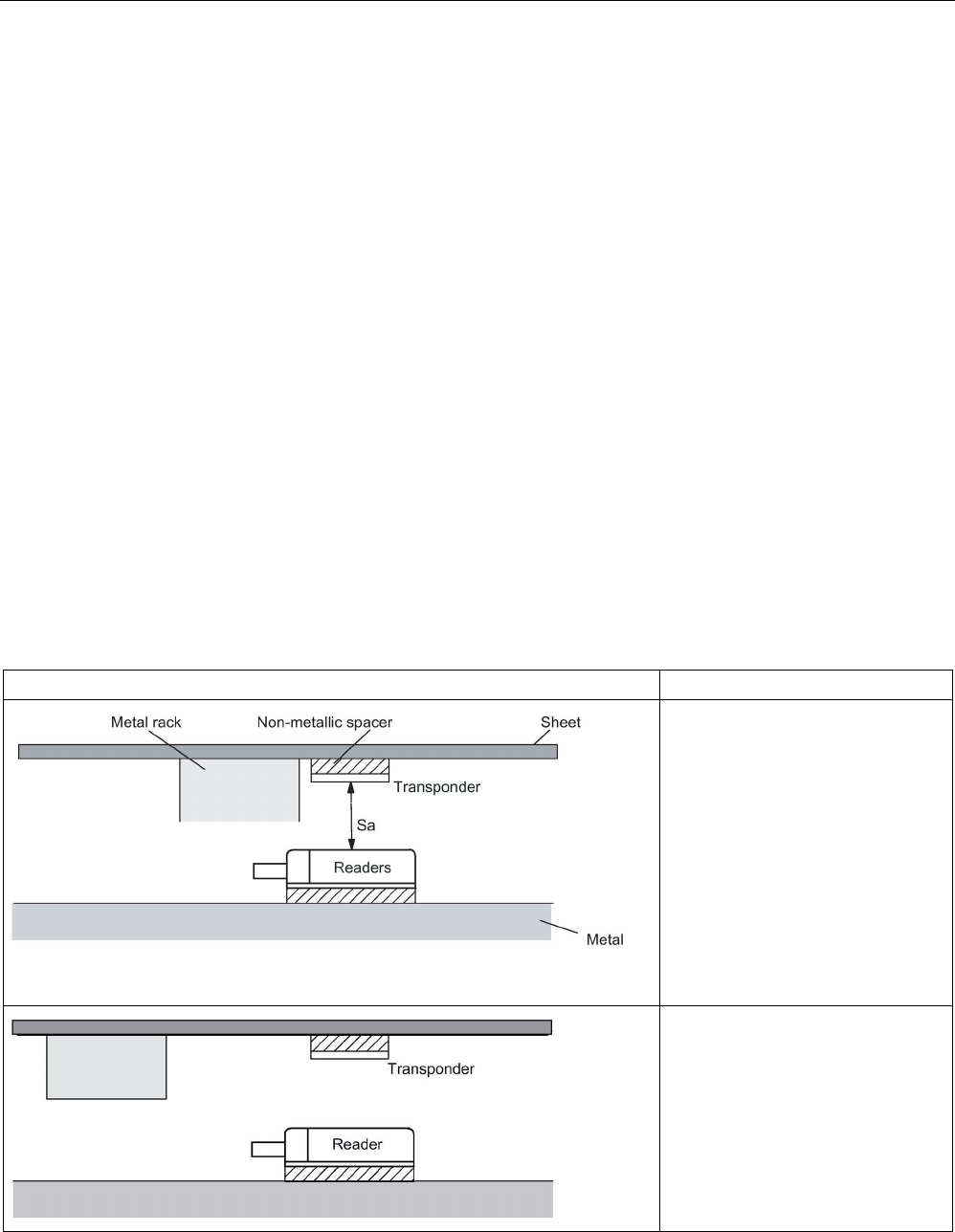
Planning the RF300 system
4.3 Installation guidelines
SIMATIC RF300
System Manual, 07/2017, C79000-G8976-C345-07 67
4.3
Installation guidelines
4.3.1
Overview
The transponder and reader complete with their antennas are inductive devices. Any type of
metal in the vicinity of these devices affects their functionality. Some points need to be
considered during planning and installation if the values described in the "Field data
(Page 51)" section are to retain their validity:
● Minimum spacing between two readers or their antennas
● Minimum distance between two adjacent data memories
● Metal-free area for flush-mounting of readers or their antennas and transponders in metal
● Mounting of multiple readers or their antennas on metal frames or racks
The following sections describe the impact on the operation of the RFID system when
mounted in the vicinity of metal.
4.3.2
Reduction of interference due to metal
Table 4- 31 Interference due to metal rack
Representation
Description
Problem:
A metal rack is located above the
transmission window of the reader.
This affects the entire field. In par-
ticular, the transmission window
between reader and transponder is
reduced.
Remedy:
The transmission window is no
longer affected if the transponder is
mounted differently.
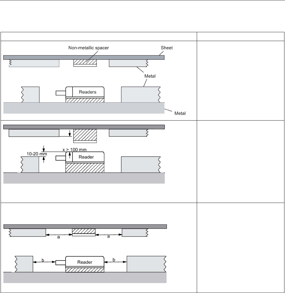
Planning the RF300 system
4.3 Installation guidelines
SIMATIC RF300
68 System Manual, 07/2017, C79000-G8976-C345-07
Table 4- 32 Flush-mounting of transponders and readers
Representation
Description
Problem:
Flush-mounting of transponders and
readers is possible in principle.
However, the size of the transmis-
sion window is significantly reduced.
The following measures can be
used to counteract the reduction of
the window:
Remedy:
Enlargement of the non-metallic
spacer below the transponder
and/or reader.
The transponder and/or reader are
10 to 20 mm higher than the metal
surround.
(The value x ≥ 100 mm is valid, e.g.
for RF310R. It indicates that, for a
distance x ≥ 100 mm, the reader
can no longer be significantly affect-
ed by metal.)
Remedy:
Increase the distances a, b to metal.
The following rule of thumb can be
used:
• Increase a, b by a factor of 2 to 3
over the values specified for
metal-free areas
• Increasing a, b has a greater
effect for readers or transpond-
ers with a large limit distance
than for readers or transponders
with a small limit distance.
Mounting of several readers on metal frames or racks
Any reader mounted on metal couples part of the field to the metal frame. There is normally
no interaction as long as the minimum distance D and metal-free areas a, b are maintained.
However, interaction may take place if an iron frame is positioned unfavorably. Longer data
transfer times or sporadic error messages at the communication module are the result.
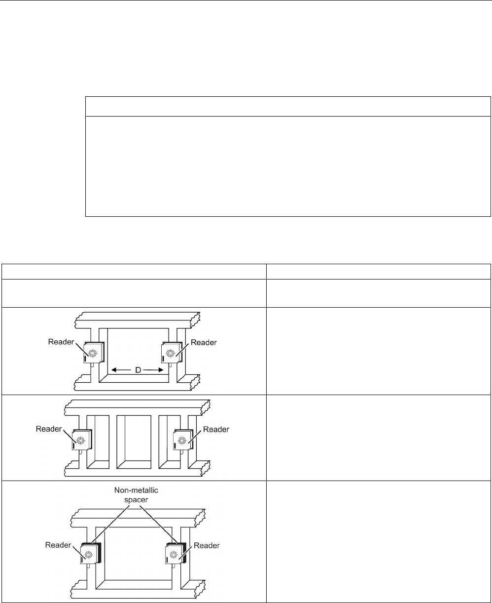
Planning the RF300 system
4.3 Installation guidelines
SIMATIC RF300
System Manual, 07/2017, C79000-G8976-C345-07 69
Note that antenna cables should not be coiled (cable coil = antenna) and should not be
mounted directly on metal when coiled to avoid coupling. Antenna cables should be laid
separately in a cable channel and not together with the signal/power supply cable of devices
(including those of the reader) or other power cables.
NOTICE
Installation of the readers on a metal construction and mixed mode
Note that if the readers are installed on a metal construction and in mixed mode 1) the
minimum spacing needs to be doubled. This also applies if you are working with external
antennas. Moreover the non-metal base on which the reader is mounted should be at least
40 mm thick.
1) RF300 operation along with ISO 15693 operation or ISO 15693 operation with MOBY E
operation etc.
Table 4- 33 Mounting of several readers on metal frames or racks
Representation
Description
Problem:
Interaction between readers
Remedy:
Increase the distance D between the two readers.
Remedy:
Introduce one or more iron struts in order to short-
circuit the stray fields.
Remedy:
Insert a non-metallic spacer of 20 to 40 millimeter
thickness between the reader and the iron frame. This
will significantly reduce the induction of stray fields on
the rack:

Planning the RF300 system
4.3 Installation guidelines
SIMATIC RF300
70 System Manual, 07/2017, C79000-G8976-C345-07
4.3.3
Effects of metal on different transponders and readers
Mounting different transponders and readers on metal or flush-mounting
Certain conditions have to be observed when mounting the transponders and readers on
metal or flush-mounting. For more information, please refer to the descriptions of the
individual transponders and readers in the relevant section.
4.3.4
Impact on the transmission window by metal
In general, the following points should be considered when mounting RFID components:
● Direct mounting on metal is allowed only in the case of specially approved transponders.
● Flush-mounting of the components in metal reduces the field data; a test is recommended
in critical applications.
● When working inside the transmission window, make sure that no metal rail (or similar
part) intersects the transmission field.
The metal rail would affect the field data.
● With readers with a large antenna surface (e.g. RF340R) for reasons of communication
reliability, when the transponders are flush-mounted in metal, a metal-free space around
the transponders is recommended. This metal-free space should match the size of the
antenna surface.
● The reduction of field data is also based on the minimum distance between the reader
and transponder. The respective recommendations are listed in the following table.
The impact of metal on the field data (Sg, Sa, L) is shown in a table in this section. The
values in the tables describe field data reduction and show the reduced range as a
percentage. The range relates to use in a non-metallic environment. A value of 100% means
no influence on the range.
Note
Possible reader-transponder combinations
The
tables of the following section show the possible reader-transponder combinations.

Planning the RF300 system
4.3 Installation guidelines
SIMATIC RF300
System Manual, 07/2017, C79000-G8976-C345-07 71
4.3.4.1
Impact on the transmission window by metal
With RF300 transponders
Table 4- 34 Reduction of field data due to metal, range as %: Transponder and RF310R
Transponder
RF310R reader
Without metal
On metal
Flush-mounted
in metal
(20 mm all-
round)
RF320T
1) Without metal 100 95 80
On metal; distance 20 mm
100
80
70
Flush-mounted in metal;
distance all round 20 mm 2)
80 70 60
RF330T
Without metal
100
95
80
On metal; distance 0 mm 100 85 75
Flush-mounted in metal;
distance all round 10 mm
85 80 70
Flush-mounted in metal;
without surrounding clearance
2)
30 30 25
RF340T
Without metal
100
95
80
On metal; distance 0 mm
80
80
80
Flush-mounted in metal;
distance all round 20 mm
3)
70 70 70
RF350T
Without metal
100
95
85
On metal; distance 0 mm
70
65
65
Flush-mounted in metal;
distance all round 20 mm
3)
60 60 60
RF360T
Without metal
100
95
85
On metal; distance 20 mm
100
95
75
Flush-mounted in metal;
distance all round 20 mm
3)
60 60 60
RF370T
Without metal
100
95
80
On metal; distance 0 mm 95 90 75
Flush-mounted in metal;
distance all round 20 mm
4)
70 65 65
1)
Mounting the transponder on or in metal is only possible with the appropriate spacer or if there is
adequate clearance to the metal.
2)
Transponder flush-mounted in metal; minimum distance to the reader is 5 mm
3)
Transponder flush-mounted in metal; minimum distance to the reader is 10 mm
4) Transponder flush-mounted in metal; minimum distance to the reader is 15 mm

Planning the RF300 system
4.3 Installation guidelines
SIMATIC RF300
72 System Manual, 07/2017, C79000-G8976-C345-07
With ISO transponders (MDS D)
Table 4- 35 Reduction of field data due to metal, range as %: Transponder and RF310R
Transponder
RF310R reader
Without metal
On metal
Flush-mounted
in metal
(20 mm all-
round)
MDS D100
1)
Without metal
100
95
80
On metal; distance 20 mm
75
70
65
Flush-mounted in metal;
distance all round 20 mm
4)
55 55 50
MDS D124
1)
Without metal
100
95
80
On metal; distance 15 mm
90
95
85
Flush-mounted in metal;
distance all round 20 mm
3)
80 75 60
MDS D126
1)
Without metal
100
90
85
On metal; distance 25 mm
85
80
75
Flush-mounted in metal;
distance all round 50 mm
3)
80 75 70
MDS D139
1)
Without metal
100
90
80
On metal; distance 30 mm
100
90
80
Flush-mounted in metal;
distance all round 100 mm
4)
100 90 80
MDS D160
1)
Without metal
100
90
80
On metal; distance 10 mm
75
75
75
MDS D165
Without metal
100
90
85
On metal; distance 25 mm
90
80
75
MDS D200
1)
Without metal
100
90
80
On metal; distance 20 mm
80
70
65
Flush-mounted in metal;
distance all round 20 mm
4)
60 60 60
MDS D261
Without metal 100 80 85
On metal; distance 25 mm
90
75
80
MDS D324
1)
Without metal
100
95
75
On metal; distance 15 mm
80
80
75
Flush-mounted in metal;
distance all round 25 mm
3)
80 75 70
MDS D339
Without metal
100
90
80
On metal; distance 30 mm
100
90
80
Flush-mounted in metal;
distance all round 100 mm
4)
100 90 80
MDS D400
1)
Without metal
100
80
75
On metal; distance 20 mm
65
60
55

Planning the RF300 system
4.3 Installation guidelines
SIMATIC RF300
System Manual, 07/2017, C79000-G8976-C345-07 73
Transponder
RF310R reader
Without metal
On metal
Flush-mounted
in metal
(20 mm all-
round)
Flush-mounted in metal;
distance all round 20 mm 4)
55 50 45
MDS D423
Without metal
100
95
90
On metal; distance 0 mm
150
5)
140
5)
140
5)
Flush-mounted in metal;
distance all round 0 mm
2)
70 60 60
MDS D424
1)
Without metal
100
90
80
On metal; distance 15 mm
80
80
70
Flush-mounted in metal;
distance all round 25 mm
2)
60 60 50
MDS D425
Without metal
100
100
95
On metal; distance 0 mm
90
85
80
MDS D426
1)
Without metal
100
90
80
On metal; distance 25 mm
85
80
70
Flush-mounted in metal;
distance all round 50 mm
3)
80 75 65
MDS D428
Without metal
100
100
75
On metal; distance 0 mm
100
100
75
MDS D460
1)
Without metal
100
100
80
On metal; distance 10 mm
80
80
60
MDS D524
1)
Without metal
100
90
80
On metal; distance 15 mm
80
80
70
Flush-mounted in metal;
distance all round 25 mm
2)
60 60 50
MDS D525
Without metal 100 100 95
On metal; distance 0 mm
90
85
80
MDS D526
1)
Without metal
100
90
80
On metal; distance 25 mm
85
80
70
Flush-mounted in metal;
distance all round 50 mm
3)
80 75 65
MDS D528
Without metal
100
100
75
On metal; distance 0 mm
100
100
75
1)
Mounting the transponder on or in metal is only possible with the appropriate spacer or if there is
adequate clearance to the metal.
2)
Transponder flush-mounted in metal; minimum distance to the reader is 5 mm
3)
Transponder flush-mounted in metal; minimum distance to the reader is 10 mm
4)
Transponder flush-mounted in metal; minimum distance to the reader is 15 mm
5)
Values of > 100 % can occur if transponders were developed specifically for mounting in/on metal-
lic surroundings.

Planning the RF300 system
4.3 Installation guidelines
SIMATIC RF300
74 System Manual, 07/2017, C79000-G8976-C345-07
With ISO transponders (MDS E)
Table 4- 36 Reduction of field data due to metal, range as %: Transponder and RF310R
Transponder
RF310R reader
Without metal
On metal
Flush-mounted
in metal
(20 mm all-
round)
MDS E600
1)
Without metal
100
95
80
On metal; distance 20 mm
75
70
65
Flush-mounted in metal;
distance all round 20 mm
3)
55 55 50
MDS E611
1)
Without metal
100
95
80
On metal; distance 20 mm
75
70
65
Flush-mounted in metal;
distance all round 20 mm
3)
55 55 50
MDS E624
1)
Without metal
100
95
80
On metal; distance 15 mm
90
95
85
Flush-mounted in metal;
distance all round 20 mm
2)
80 75 60
1)
Mounting the transponder on or in metal is only possible with the appropriate spacer or if there is
adequate clearance to the metal.
2)
Transponder flush-mounted in metal; minimum distance to the reader is 5 mm
3) Transponder flush-mounted in metal; minimum distance to the reader is 10 mm

Planning the RF300 system
4.3 Installation guidelines
SIMATIC RF300
System Manual, 07/2017, C79000-G8976-C345-07 75
4.3.4.2
RF340R
With RF300 transponders
Table 4- 37 Reduction of field data due to metal, range as %: Transponder and RF340R
Transponder
RF340R reader
Without metal
On metal
Flush-mounted
in metal
(20 mm all-
round)
RF320T
Without metal 100 95 90
On metal; distance 20 mm
85
85
80
Flush-mounted in metal;
distance all round 20 mm 3)
75 75 65
RF330T
1)
Without metal
100
95
90
On metal; distance 0 mm 90 90 80
Flush-mounted in metal;
distance all round 10 mm
3)
65 65 60
RF340T
Without metal
100
95
80
On metal; distance 0 mm
65
65
55
Flush-mounted in metal;
distance all round 20 mm
3)
60 60 55
RF350T
Without metal
100
90
85
On metal; distance 0 mm
75
70
70
Flush-mounted in metal;
distance all round 20 mm
3)
55 55 45
RF360T
Without metal
100
95
80
On metal; distance 20 mm
75
70
65
Flush-mounted in metal;
distance all round 20 mm
3)
70 60 50
RF370T
Without metal
100
95
80
On metal; distance 0 mm
95
90
75
Flush-mounted in metal;
distance all round 20 mm 4)
70 65 65
RF380T
Without metal
100
95
75
On metal; distance 0 mm 100 95 70
Flush-mounted in metal;
distance all round 40 mm
4)
80 75 60
1)
Mounting the transponder on or in metal is only possible with the appropriate spacer or if there is
adequate clearance to the metal.
2)
Transponder flush-mounted in metal; minimum distance to the reader is 5 mm
3)
Transponder flush-mounted in metal; minimum distance to the reader is 10 mm
4) Transponder flush-mounted in metal; minimum distance to the reader is 15 mm

Planning the RF300 system
4.3 Installation guidelines
SIMATIC RF300
76 System Manual, 07/2017, C79000-G8976-C345-07
With ISO transponders (MDS D)
Table 4- 38 Reduction of field data due to metal, range as %: Transponder and RF340R
Transponder
RF340R reader
Without metal
On metal
Flush-mounted
in metal
(20 mm all-
round)
MDS D100
1)
Without metal
100
90
75
On metal; distance 20 mm
70
65
60
Flush-mounted in metal;
distance all round 20 mm
4)
60 45 45
MDS D124
1)
Without metal
100
95
80
On metal; distance 15 mm
85
85
75
Flush-mounted in metal;
distance all round 20 mm
2)
80 80 45
MDS D126
1)
Without metal
100
90
85
On metal; distance 25 mm
80
80
70
Flush-mounted in metal;
distance all round 50 mm
3)
75 75 65
MDS D139
1)
Without metal
100
95
80
On metal; distance 30 mm
100
90
75
Flush-mounted in metal;
distance all round 100 mm
4)
100 90 75
MDS D160
1)
Without metal
100
95
80
On metal; distance 10 mm
85
85
75
MDS D165
Without metal
100
95
85
On metal, distance 25 mm
4)
90
80
75
MDS D200
1)
Without metal
100
95
90
On metal; distance 20 mm
90
85
80
Flush-mounted in metal;
distance all round 20 mm
3)
75 50 65
MDS D261
Without metal 100 100 100
On metal, distance 25 mm
3)
70
95
90
MDS D324
1)
Without metal
100
95
80
On metal; distance 15 mm
90
85
75
Flush-mounted in metal;
distance all round 25 mm
2)
80 80 60
MDS D339
Without metal
100
95
80
On metal; distance 30 mm
100
90
75
Flush-mounted in metal;
distance all round 100 mm
4)
100 90 75
MDS D400
1)
Without metal
100
90
80
On metal; distance 20 mm
70
65
80

Planning the RF300 system
4.3 Installation guidelines
SIMATIC RF300
System Manual, 07/2017, C79000-G8976-C345-07 77
Transponder
RF340R reader
Without metal
On metal
Flush-mounted
in metal
(20 mm all-
round)
Flush-mounted in metal;
distance all round 20 mm 3)
55 50 50
MDS D423
Without metal
100
95
85
On metal; distance 0 mm
120
5)
120
5)
115
5)
Flush-mounted in metal;
distance all round 0 mm
2)
65 60 60
MDS D424
1)
Without metal
100
95
80
On metal; distance 15 mm
85
85
75
Flush-mounted in metal;
distance all round 25 mm
3)
75 75 70
MDS D425
Without metal
100
95
95
On metal; distance 0 mm
100
90
90
MDS D426
1)
Without metal
100
90
80
On metal; distance 25 mm
80
75
70
Flush-mounted in metal;
distance all round 50 mm
3)
75 70 65
MDS D428
Without metal
100
95
80
On metal; distance 0 mm
95
80
75
MDS D460
1)
Without metal
100
95
95
On metal; distance 10 mm
85
85
85
MDS D524
1)
Without metal
100
95
80
On metal; distance 15 mm
85
85
75
Flush-mounted in metal;
distance all round 25 mm
3)
75 75 70
MDS D525
Without metal 100 95 95
On metal; distance 0 mm
100
90
90
MDS D526
1)
Without metal
100
90
80
On metal; distance 25 mm
80
75
70
Flush-mounted in metal;
distance all round 50 mm
3)
75 70 65
MDS D528
Without metal
100
95
80
On metal; distance 0 mm
95
80
75
1)
Mounting the transponder on or in metal is only possible with the appropriate spacer or if there is
adequate clearance to the metal.
2)
Transponder flush-mounted in metal; minimum distance to the reader is 5 mm
3)
Transponder flush-mounted in metal; minimum distance to the reader is 10 mm
4)
Transponder flush-mounted in metal; minimum distance to the reader is 15 mm
5)
Values of > 100 % can occur if transponders were developed specifically for mounting in/on metal-
lic surroundings.

Planning the RF300 system
4.3 Installation guidelines
SIMATIC RF300
78 System Manual, 07/2017, C79000-G8976-C345-07
With ISO transponders (MDS E)
Table 4- 39 Reduction of field data due to metal, range as %: Transponder and RF340R
Transponder
RF340R reader
Without metal
On metal
Flush-mounted
in metal
(20 mm all-
round)
MDS E600
1)
Without metal
100
90
75
On metal; distance 20 mm
70
65
60
Flush-mounted in metal;
distance all round 20 mm
3)
60 45 45
MDS E611
1)
Without metal
100
90
75
On metal; distance 20 mm
70
65
60
Flush-mounted in metal;
distance all round 20 mm
3)
60 45 45
MDS E624
1)
Without metal
100
95
80
On metal; distance 15 mm
85
85
75
Flush-mounted in metal;
distance all round 20 mm
2)
80 80 45
1)
Mounting the transponder on or in metal is only possible with the appropriate spacer or if there is
adequate clearance to the metal.
2)
Transponder flush-mounted in metal; minimum distance to the reader is 5 mm
3) Transponder flush-mounted in metal; minimum distance to the reader is 15 mm

Planning the RF300 system
4.3 Installation guidelines
SIMATIC RF300
System Manual, 07/2017, C79000-G8976-C345-07 79
4.3.4.3
RF350R
Reader RF350R with ANT 1 and with RF300 transponders
Table 4- 40 Reduction of field data due to metal, range as %: Transponder and RF350R with ANT 1
Transponder
ANT 1 without
metal
ANT 1 on metal
ANT 1 flush-
mounted in
metal
(40 mm all-
round)
RF320T
1)
Without metal
100
90
90
On metal; distance 20 mm
85
85
75
Flush-mounted in metal;
distance all round 20 mm
75 75 65
RF330T
Without metal 100 90 90
On metal; distance 0 mm
95
85
75
Flush-mounted in metal;
distance all round 10 mm
65 60 60
RF340T
Without metal
100
90
90
On metal; distance 0 mm
65
65
60
Flush-mounted in metal;
distance all round 20 mm
60 60 55
RF350T
Without metal
100
90
85
On metal; distance 0 mm
75
70
65
Flush-mounted in metal;
distance all round 20 mm
55 55 45
RF360T
Without metal
100
90
85
On metal; distance 20 mm
75
75
65
Flush-mounted in metal;
distance all round 20 mm
65 60 50
RF370T
Without metal
100
90
85
On metal; distance 0 mm
95
88
75
Flush-mounted in metal;
distance all round 20 mm
70 65 65
RF380T
Without metal 100 90 80
On metal; distance 0 mm
100
90
70
Flush-mounted in metal;
distance all round 40 mm
80 75 60
1)
Mounting the transponder on or in metal is only possible with the appropriate spacer or if there is
adequate clearance to the metal.
Note
The minimum distances are listed in section "
RF340R (Page 75)".

Planning the RF300 system
4.3 Installation guidelines
SIMATIC RF300
80 System Manual, 07/2017, C79000-G8976-C345-07
Reader RF350R with ANT 1 and with ISO transponders (MDS D)
Table 4- 41 Reduction of field data due to metal, range as %: Transponder and RF350R with ANT 1
Transponder
ANT 1 without
metal
ANT 1 on metal
ANT 1 mounted
in metal
(40 mm all-
round)
MDS D100
1)
Without metal
100
85
80
On metal; distance 20 mm 70 60 65
Flush-mounted in metal;
distance all round 20 mm
60 45 45
MDS D124
1) Without metal 100 95 85
On metal; distance 15 mm
85
85
80
Flush-mounted in metal;
distance all round 20 mm
85 80 50
MDS D126
1)
Without metal
100
85
85
On metal; distance 25 mm
85
75
75
Flush-mounted in metal;
distance all round 50 mm
80 70 70
MDS D139
1)
Without metal
100
90
85
On metal; distance 30 mm
95
85
85
Flush-mounted in metal;
distance all round 100 mm
95 85 85
MDS D160
1)
Without metal
100
95
90
On metal; distance 10 mm
85
85
80
MDS D165
Without metal
100
85
85
On metal; distance 25 mm
90
80
75
MDS D200
1)
Without metal
100
85
80
On metal; distance 20 mm
85
75
75
Flush-mounted in metal;
distance all round 20 mm
75 65 65
MDS D261
Without metal
100
90
85
On metal; distance 25 mm
85
80
80
MDS D324
1)
Without metal
100
85
85
On metal; distance 15 mm 90 80 80
Flush-mounted in metal;
distance all round 25 mm
80 75 65
MDS D339
1)
Without metal
100
90
85
On metal; distance 30 mm
95
85
85
Flush-mounted in metal;
distance all round 100 mm
95 85 85
MDS D400
1)
Without metal
100
90
85
On metal; distance 20 mm
80
70
65
Flush-mounted in metal;
distance all round 20 mm
65 60 60

Planning the RF300 system
4.3 Installation guidelines
SIMATIC RF300
System Manual, 07/2017, C79000-G8976-C345-07 81
Transponder
ANT 1 without
metal
ANT 1 on metal
ANT 1 mounted
in metal
(40 mm all-
round)
MDS D423
Without metal
100
90
90
On metal; distance 0 mm 1152) 1152) 1152)
Flush-mounted in metal;
distance all round 0 mm
80 65 65
MDS D424
1) Without metal 100 90 75
On metal; distance 15 mm
85
80
75
Flush-mounted in metal;
distance all round 25 mm
75 70 70
MDS D425
Without metal
100
95
95
On metal; distance 0 mm
90
85
85
MDS D426
1)
Without metal
100
90
85
On metal; distance 25 mm
85
80
75
Flush-mounted in metal;
distance all round 50 mm
80 75 70
MDS D428
Without metal
100
90
85
On metal; distance 0 mm
85
80
80
MDS D460
1)
Without metal
100
90
80
On metal; distance 10 mm
85
80
75
MDS D524
1)
Without metal
100
90
75
On metal; distance 15 mm
85
80
75
Flush-mounted in metal;
distance all round 25 mm
75 70 70
MDS D525
Without metal 100 95 95
On metal; distance 0 mm
90
85
85
MDS D526
1) Without metal 100 90 85
On metal; distance 25 mm
85
80
75
Flush-mounted in metal;
distance all round 50 mm
80 75 70
MDS D528
Without metal
100
90
85
On metal; distance 0 mm
85
80
80
1)
Mounting the transponder on or in metal is only possible with the appropriate spacer or if there is
adequate clearance to the metal.
2)
Values of > 100 % can occur if transponders were developed specifically for mounting in/on metal-
lic surroundings.
Note
The minimum distances are listed in section "
RF340R (Page 75)".

Planning the RF300 system
4.3 Installation guidelines
SIMATIC RF300
82 System Manual, 07/2017, C79000-G8976-C345-07
Reader RF350R with ANT 1 and with ISO transponders (MDS E)
Table 4- 42 Reduction of field data due to metal, range as %: Transponder and RF350R with ANT 1
Transponder
ANT 1 without
metal
ANT 1 on metal
ANT 1 mounted
in metal
(40 mm all-
round)
MDS E600
1)
Without metal
100
85
80
On metal; distance 20 mm 70 60 65
Flush-mounted in metal;
distance all round 20 mm
60 45 45
MDS E611
1) Without metal 100 85 80
On metal; distance 20 mm
70
60
65
Flush-mounted in metal;
distance all round 20 mm
60 45 45
MDS E624
1)
Without metal
100
95
85
On metal; distance 15 mm
85
85
80
Flush-mounted in metal;
distance all round 20 mm
85 80 50
1)
Mounting the transponder on or in metal is only possible with the appropriate spacer or if there is
adequate clearance to the metal.
Note
The minimum distances are listed in section "
RF340R (Page 75)".
Reader RF350R with ANT 3 and with RF300 transponders
Table 4- 43 Reduction of field data due to metal, range as %: Transponder and RF350R with ANT 3
Transponder
ANT 3 without
metal
ANT 3 on metal
ANT 3 flush-
mounted in
metal
(40 mm all-
round)
RF320T
1)
Without metal
100
90
90
On metal; distance 20 mm 35 35 35
Flush-mounted in metal;
distance all round 20 mm
2)
35 25 15
RF330T
Without metal 100 100 100
On metal; distance 0 mm
117
106
106
Flush-mounted in metal;
distance all round 10 mm
2)
128 128 128

Planning the RF300 system
4.3 Installation guidelines
SIMATIC RF300
System Manual, 07/2017, C79000-G8976-C345-07 83
Transponder
ANT 3 without
metal
ANT 3 on metal
ANT 3 flush-
mounted in
metal
(40 mm all-
round)
RF340T
Without metal
100
75
70
On metal; distance 0 mm 70 75 63
Flush-mounted in metal;
distance all round 20 mm
2)
63 63 58
RF350T
Without metal 100 75 75
On metal; distance 0 mm
70
75
75
Flush-mounted in metal;
distance all round 20 mm
2)
63 63 58
1)
Mounting the transponder on or in metal is only possible with the appropriate spacer or if there is
adequate clearance to the metal.
2) Transponder flush-mounted in metal; minimum distance to the reader is 5 mm
Reader RF350R with ANT 3 and with ISO transponders (MDS D)
Table 4- 44 Reduction of field data due to metal, range as %: Transponder and RF350R with ANT 3
Transponder
ANT 3 without
metal
ANT 3 on metal
ANT 3 flush-
mounted in
metal
(40 mm all-
round)
MDS D124
1)
Without metal
100
100
90
On metal; distance 20 mm
33
24
21
Flush-mounted in metal;
distance all round 20 mm
24 24 17
MDS D160
1)
Without metal
100
100
95
On metal; distance 0 mm
16
16
21
Flush-mounted in metal; dis-
tance all round 10 mm
24 18 13
MDS D324
1)
Without metal
100
100
92
On metal; distance 0 mm
47
34
29
Flush-mounted in metal;
distance all round 20 mm
29 24 18
MDS D421
MDS D521
Without metal 100 100 100
On metal; distance 0 mm
110
110
110
Flush-mounted in metal; dis-
tance all round 0 mm
90 50 50
MDS D422
MDS D522
Without metal
100
100
83
On metal, distance 0 mm
111
111
111
Flush-mounted in metal;
distance all round 20 mm
83 56 39

Planning the RF300 system
4.3 Installation guidelines
SIMATIC RF300
84 System Manual, 07/2017, C79000-G8976-C345-07
Transponder
ANT 3 without
metal
ANT 3 on metal
ANT 3 flush-
mounted in
metal
(40 mm all-
round)
MDS D423
Without metal
100
100
93
On metal; distance 0 mm 125 125 121
Flush-mounted in metal;
distance all round 20 mm
125 143 136
MDS D424
1)
MDS D524
Without metal 100 100 94
On metal; distance 0 mm
23
23
21
Flush-mounted in metal;
distance all round 20 mm
17 13 10
MDS D425
MDS D525
Without metal
100
100
100
On metal; distance 0 mm
89
100
71
Flush-mounted in metal; dis-
tance all round 20 mm
71 54 36
MDS D428
MDS D528
Without metal
100
93
83
On metal; distance 0 mm
93
93
83
Flush-mounted in metal; dis-
tance all round 20 mm
93 93 83
MDS D460
1)
Without metal
100
93
90
On metal; distance 0 mm
33
33
20
Flush-mounted in metal; dis-
tance all round 20 mm
33 33 17
1)
Mounting the transponder on or in metal is only possible with the appropriate spacer or if there is
adequate clearance to the metal.
2)
Values of > 100 % can occur if transponders were developed specifically for mounting in/on metal-
lic surroundings.

Planning the RF300 system
4.3 Installation guidelines
SIMATIC RF300
System Manual, 07/2017, C79000-G8976-C345-07 85
Reader RF350R with ANT 3 and with ISO transponders (MDS E)
Table 4- 45 Reduction of field data due to metal, range as %: Transponder and RF350R with ANT 3
Transponder
ANT 3 without
metal
ANT 3 on metal
ANT 3 flush-
mounted in
metal
(40 mm all-
round)
MDS E624
1)
Without metal
100
100
94
On metal; distance 0 mm 23 23 21
Flush-mounted in metal;
distance all round 20 mm
17 13 10
1)
Mounting the transponder on or in metal is only possible with the appropriate spacer or if there is
adequate clearance to the metal.
Reader RF350R with ANT 12 and with ISO transponders (MDS D)
Table 4- 46 Reduction of field data due to metal, range as %: Transponder and RF350R with ANT 12
Transponder
ANT 12 without metal
ANT 12 mounted in met-
al
(0 mm all-round)
MDS D117
Without metal
100
85
On metal; distance 0 mm
90
85
Flush-mounted in metal;
distance all round 0 mm
65 65
MDS D127
Without metal
100
85
On metal; distance 0 mm
95
85
Flush-mounted in metal;
distance all round 0 mm
65 65
MDS D160
1)
Without metal
100
80
On metal; distance 10 mm
100
80
MDS D421
Without metal
100
80
On metal; distance 0 mm
90
75
Flush-mounted in metal;
distance all round 0 mm
70 60
MDS D428
Without metal
100
75
On metal; distance 0 mm
95
75
MDS D460
1)
Without metal
100
80
On metal; distance 10 mm 100 80
MDS D521
Without metal
100
80
On metal; distance 0 mm 90 75
Flush-mounted in metal;
distance all round 0 mm
70 60

Planning the RF300 system
4.3 Installation guidelines
SIMATIC RF300
86 System Manual, 07/2017, C79000-G8976-C345-07
Transponder
ANT 12 without metal
ANT 12 mounted in met-
al
(0 mm all-round)
MDS D528
Without metal
100
75
On metal; distance 0 mm 95 75
1)
Mounting the transponder on or in metal is only possible with the appropriate spacer or if there is
adequate clearance to the metal.
Reader RF350R with ANT 12 and with ISO transponders (MDS E)
Table 4- 47 Reduction of field data due to metal, range as %: Transponder and RF350R with ANT 12
Transponder
ANT 12 without metal
ANT 12 mounted in met-
al
(0 mm all-round)
MDS E623
Without metal
100
80
On metal; distance 0 mm
90
75
Flush-mounted in metal;
distance all round 0 mm
70 60
1)
Mounting the transponder on or in metal is only possible with the appropriate spacer or if there is
adequate clearance to the metal.

Planning the RF300 system
4.3 Installation guidelines
SIMATIC RF300
System Manual, 07/2017, C79000-G8976-C345-07 87
Reader RF350R with ANT 18 and with RF300 transponders
Table 4- 48 Reduction of field data due to metal, range as %: Transponder and RF350R with ANT 18
Transponder
ANT 18 without metal
ANT 18 mounted in met-
al
(10 mm all-round)
RF320T
1)
Without metal
100
65
On metal; distance 20 mm 85 55
Flush-mounted in metal;
distance all round 20 mm
75 45
RF330T
Without metal 100 85
On metal; distance 0 mm
120
2)
100
Flush-mounted in metal;
distance all round 10 mm
1152) 95
Flush-mounted in metal;
without surrounding clearance
95 90
RF340T
Without metal
100
85
On metal; distance 0 mm
65
60
Flush-mounted in metal;
distance all round 20 mm
60 55
1)
Mounting the transponder on or in metal is only possible with the appropriate spacer or if there is
adequate clearance to the metal.
2)
Values of > 100 % can occur if transponders were developed specifically for mounting in/on metal-
lic surroundings.
Reader RF350R with ANT 18 and with ISO transponders (MDS D)
Table 4- 49 Reduction of field data due to metal, range as %: Transponder and RF350R with ANT 18
Transponder
ANT 18 without metal
ANT 18 mounted in met-
al
(10 mm all-round)
MDS D124
1)
Without metal
100
85
On metal, distance 15 mm
85
75
Flush-mounted in metal;
distance all round 15 mm
85 45
MDS D127
Without metal
100
90
On metal, distance 0 mm
95
85
Flush-mounted in metal;
distance all round 0 mm
60 60
MDS D160
1)
Without metal
100
80
On metal, distance 10 mm 85 75
MDS D324
1)
Without metal
100
80
On metal; distance 15 mm
90
75

Planning the RF300 system
4.3 Installation guidelines
SIMATIC RF300
88 System Manual, 07/2017, C79000-G8976-C345-07
Transponder
ANT 18 without metal
ANT 18 mounted in met-
al
(10 mm all-round)
Flush-mounted in metal;
distance all round 25 mm
80 65
MDS D421
Without metal
100
85
On metal, distance 0 mm
90
65
Flush-mounted in metal;
distance all round 0 mm
40 20
MDS D422
Without metal
100
85
On metal, distance 0 mm
95
85
Flush-mounted in metal;
distance all round 0 mm
90 80
MDS D424
1)
Without metal
100
85
On metal 15 mm
85
80
Flush-mounted in metal;
distance all round 25 mm
75 75
MDS D425
Without metal
100
85
On metal, distance 0 mm
100
85
MDS D428
Without metal
100
95
On metal, distance 0 mm
95
95
MDS D460
1)
Without metal
100
95
On metal, distance 15 mm
95
95
MDS D521
Without metal
100
85
On metal, distance 0 mm
90
65
Flush-mounted in metal;
distance all round 0 mm
40 20
MDS D522
Without metal
100
85
On metal, distance 0 mm
95
85
Flush-mounted in metal;
distance all round 0 mm
90 80
MDS D524
1)
Without metal
100
85
On metal 15 mm
85
80
Flush-mounted in metal;
distance all round 25 mm
75 75
MDS D525
Without metal
100
85
On metal, distance 0 mm
100
85
MDS D528
Without metal
100
95
On metal, distance 0 mm
95
95
1)
Mounting the transponder on or in metal is only possible with the appropriate spacer or if there is
adequate clearance to the metal.

Planning the RF300 system
4.3 Installation guidelines
SIMATIC RF300
System Manual, 07/2017, C79000-G8976-C345-07 89
Reader RF350R with ANT 18 and with ISO transponders (MDS E)
Table 4- 50 Reduction of field data due to metal, range as %: Transponder and RF350R with ANT 18
Transponder
ANT 18 without metal
ANT 18 mounted in met-
al
(10 mm all-round)
MDS E623
Without metal
100
85
On metal, distance 0 mm 90 65
Flush-mounted in metal;
distance all round 0 mm
40 20
MDS E624
1) Without metal 100 85
On metal, distance 15 mm
85
75
Flush-mounted in metal;
distance all round 15 mm
85 45
1)
Mounting the transponder on or in metal is only possible with the appropriate spacer or if there is
adequate clearance to the metal.

Planning the RF300 system
4.3 Installation guidelines
SIMATIC RF300
90 System Manual, 07/2017, C79000-G8976-C345-07
Reader RF350R with ANT 30 and with RF300 transponders
Table 4- 51 Reduction of field data due to metal, range as %: Transponder and RF350R with ANT 30
Transponder
Mounting the antenna
ANT 30 without metal
ANT 30 mounted in met-
al
(20 mm all-round)
RF320T
1)
Without metal
100
90
On metal; distance 30 mm
85
75
Flush-mounted in metal;
distance all round 20 mm
75 65
RF330T
Without metal
100
90
On metal;
110
2)
100
Flush-mounted in metal;
distance all round 10 mm
1052) 95
Flush-mounted in metal;
without surrounding clearance
90 80
RF340T
Without metal
100
85
On metal; distance 30 mm
65
55
Flush-mounted in metal;
distance all round 20 mm
60 55
RF350T
Without metal
100
85
Directly on metal
75
65
Flush-mounted in metal;
distance all round 20 mm
55 45
RF360T
Without metal
100
75
On metal; distance 20 mm
75
55
Flush-mounted in metal;
distance all round 20 mm
50 35
1)
Mounting the transponder on or in metal is only possible with the appropriate spacer or if there is
adequate clearance to the metal.
2)
Values of > 100 % can occur if transponders were developed specifically for mounting in/on metal-
lic surroundings.

Planning the RF300 system
4.3 Installation guidelines
SIMATIC RF300
System Manual, 07/2017, C79000-G8976-C345-07 91
Reader RF350R with ANT 30 and with ISO transponders (MDS D)
Table 4- 52 Reduction of field data due to metal, range as %: Transponder and RF350R with ANT 30
Transponder
ANT 30 without metal
ANT 30 mounted in met-
al
(20 mm all-round)
MDS D124
1)
Without metal
100
85
On metal; distance 15 mm 85 75
Flush-mounted in metal;
distance all round 15 mm
80 45
MDS D126
1) Without metal 100 85
On metal; distance 25 mm
90
75
Flush-mounted in metal;
distance all round 50 mm
85 70
MDS D160
1)
Without metal
100
80
On metal, distance 10 mm
85
75
MDS D324
1)
Without metal
100
80
On metal; distance 15 mm
90
70
Flush-mounted in metal;
distance all round 25 mm
80 65
MDS D422
Without metal
100
85
On metal, distance 0 mm
95
85
Flush-mounted in metal;
distance all round 0 mm
90 80
MDS D423
Without metal
100
80
On metal, distance 0 mm
125
2)
115
2)
Flush-mounted in metal;
distance all round 0 mm
80 70
MDS D424
1)
Without metal
100
85
On metal 15 mm
95
85
Flush-mounted in metal;
distance all round 25 mm
85 75
MDS D425
Without metal
100
80
On metal, distance 0 mm
95
80
MDS D426
1)
Without metal
100
85
On metal; distance 25 mm
90
75
Flush-mounted in metal;
distance all round 50 mm
80 70
MDS D428
Without metal
100
90
On metal, distance 0 mm
95
90
MDS D460
1)
Without metal
100
90
On metal, distance 10 mm
95
85
MDS D522
Without metal
100
85
On metal, distance 0 mm
95
85

Planning the RF300 system
4.3 Installation guidelines
SIMATIC RF300
92 System Manual, 07/2017, C79000-G8976-C345-07
Transponder
ANT 30 without metal
ANT 30 mounted in met-
al
(20 mm all-round)
Flush-mounted in metal;
distance all round 0 mm
90 80
MDS D524
1)
Without metal
100
85
On metal 15 mm
95
85
Flush-mounted in metal;
distance all round 25 mm
85 75
MDS D525
Without metal
100
80
On metal, distance 0 mm
95
80
MDS D526
1)
Without metal
100
85
On metal; distance 25 mm
90
75
Flush-mounted in metal;
distance all round 50 mm
80 70
MDS D528
Without metal
100
90
On metal, distance 0 mm
95
90
1)
Mounting the transponder on or in metal is only possible with the appropriate spacer or if there is
adequate clearance to the metal.
2)
Values of > 100 % can occur if transponders were developed specifically for mounting in/on metal-
lic surroundings.
Reader RF350R with ANT 30 and with ISO transponders (MDS E)
Table 4- 53 Reduction of field data due to metal, range as %: Transponder and RF350R with ANT 30
Transponder
ANT 30 without metal
ANT 30 mounted in met-
al
(20 mm all-round)
MDS E624
1)
Without metal
100
85
On metal; distance 15 mm
85
75
Flush-mounted in metal;
distance all round 15 mm
80 45
1)
Mounting the transponder on or in metal is only possible with the appropriate spacer or if there is
adequate clearance to the metal.

Planning the RF300 system
4.3 Installation guidelines
SIMATIC RF300
System Manual, 07/2017, C79000-G8976-C345-07 93
4.3.4.4
RF380R
With RF300 transponders
Table 4- 54 Reduction of field data due to metal, range as %: Transponder and RF380R
Transponder
Reader RF380R (RF300 mode)
Without metal
On metal
Flush-mounted
in metal
(20 mm all-
round)
RF320T
1) Without metal 100 95 90
On metal; distance 20 mm
85
75
70
Flush-mounted in metal;
distance all round 20 mm 5)
60 55 50
RF330T
Without metal
100
90
80
on metal, distance 0 mm 4) 70 65 60
RF340T
Without metal
100
90
80
On metal; distance 0 mm
70
65
60
Flush-mounted in metal;
distance all round 20 mm
2)
60 60 55
RF350T
Without metal
100
85
80
On metal; distance 0 mm
70
65
60
Flush-mounted in metal;
distance all round 20 mm 2)
55 50 45
RF360T
1)
Without metal
100
95
85
On metal; distance 20 mm
75
70
65
Flush-mounted in metal;
distance all round 20 mm
3)
60 55 50
RF370T
Without metal
100
95
85
On metal; distance 0 mm
90
85
80
Flush-mounted in metal;
distance all round 20 mm
4)
65 60 60
RF380T
Without metal 100 95 85
On metal; distance 0 mm
95
90
80
Flush-mounted in metal;
distance all round 40 mm 4) 6)
65 60 55
1)
Mounting the transponder on or in metal is only possible with the appropriate spacer or if there is
adequate clearance to the metal.
2)
Transponder flush-mounted in metal; minimum distance to the reader is 5 mm
3)
Transponder flush-mounted in metal; minimum distance to the reader is 10 mm
4)
Transponder flush-mounted in metal; minimum distance to the reader is 15 mm
5)
Transponder flush-mounted in metal; minimum distance to the reader is 20 mm
6) Transponder flush-mounted in metal; minimum distance to the reader is 25 mm

Planning the RF300 system
4.3 Installation guidelines
SIMATIC RF300
94 System Manual, 07/2017, C79000-G8976-C345-07
With ISO transponders (MDS D)
Table 4- 55 Reduction of field data due to metal, range as %: Transponder and RF380R
Transponder
Reader RF380R (ISO mode)
Without metal
On metal
Flush-mounted
in metal
(20 mm all-
round)
MDS D100
1)
Without metal
100
95
80
On metal; distance 20 mm
65
60
55
Flush-mounted in metal;
distance all round 20 mm
2)
55 50 45
MDS D124
1)
Without metal
100
95
90
On metal; distance 15 mm
95
90
85
Flush-mounted in metal;
distance all round 20 mm
2)
70 65 50
MDS D126
1)
Without metal
100
90
80
On metal; distance 25 mm
80
75
70
Flush-mounted in metal;
distance all round 50 mm
3)
75 65 65
MDS D139
1)
Without metal
100
90
75
On metal; distance 30 mm
95
85
70
Flush-mounted in metal;
distance all round 100 mm
4)
90 80 70
MDS D160
1)
Without metal
100
95
90
on metal, distance 10 mm
2)
85
85
80
MDS D165
Without metal
100
90
80
On metal, distance 25 mm
4)
80
75
70
MDS D200
1)
Without metal
100
90
80
On metal; distance 20 mm
80
75
70
Flush-mounted in metal;
distance all round 20 mm
3)
65 60 55
MDS D261
Without metal 100 95 85
On metal, distance 25 mm
4)
85
80
75
MDS D324
1)
Without metal
100
95
85
On metal; distance 15 mm
85
85
80
Flush-mounted in metal;
distance all round 25 mm
2)
70 65 60
MDS D339
1)
Without metal
100
90
80
On metal; distance 30 mm
85
80
75
Flush-mounted in metal;
distance all round 100 mm
5)
80 75 70
MDS D400
1)
Without metal
100
90
80
On metal; distance 20 mm
75
70
60

Planning the RF300 system
4.3 Installation guidelines
SIMATIC RF300
System Manual, 07/2017, C79000-G8976-C345-07 95
Transponder
Reader RF380R (ISO mode)
Without metal
On metal
Flush-mounted
in metal
(20 mm all-
round)
Flush-mounted in metal;
distance all round 20 mm 4)
60 60 55
MDS D423
Without metal
100
95
85
On metal; distance 0 mm
100
100
90
Flush-mounted in metal;
distance all round 10 mm
2)
75 65 60
MDS D424
1)
MDS D524
1)
Without metal
100
90
75
On metal; distance 15 mm
75
75
60
Flush-mounted in metal;
distance all round 25 mm
3)
60 55 40
MDS D425
MDS D525
Without metal
100
70
90
On metal, distance 0 mm
2)
75
70
60
MDS D426
1)
MDS D526
1)
Without metal
100
90
80
On metal; distance 25 mm
80
75
70
Flush-mounted in metal;
distance all round 50 mm
3)
75 65 65
MDS D428
MDS D528
Without metal
100
90
80
On metal, distance 0 mm
2)
85
80
65
MDS D460
1)
Without metal
100
95
80
On metal, distance 10 mm
2)
80
75
60
MDS E600
Without metal
100
95
90
On metal, distance 20 mm
80
75
60
Flush-mounted in metal; dis-
tance all round 20 mm
65 65 60
MDS E611
Without metal 100 95 85
On metal, distance 20 mm
65
60
55
Flush-mounted in metal; dis-
tance all round 20 mm
50 50 45
MDS E624
Without metal
100
95
90
On metal, distance 15 mm
75
75
70
Flush-mounted in metal; dis-
tance all round 25 mm
60 60 55
1)
Mounting the transponder on or in metal is only possible with the appropriate spacer or if there is
adequate clearance to the metal.
2)
Transponder flush-mounted in metal; minimum distance to the reader is 5 mm
3)
Transponder flush-mounted in metal; minimum distance to the reader is 10 mm
4)
Transponder flush-mounted in metal; minimum distance to the reader is 15 mm
5) Transponder flush-mounted in metal; minimum distance to the reader is 20 mm

Planning the RF300 system
4.3 Installation guidelines
SIMATIC RF300
96 System Manual, 07/2017, C79000-G8976-C345-07
4.3.4.5
RF382R
Note
RF382R not suitable for metallic surroundings
The RF382R was not developed for reading transponders in a metallic environment.
With ISO transponders (MDS D)
Table 4- 56 Reduction of field data by metal (in %): Transponder and RF382R
Transponder
Reader RF382R (ISO mode)
Without metal
On metal
MDS D124
Without metal
100
110
1)
MDS D160
Without metal
100
100
MDS D324
Without metal
100
110
1)
MDS D424
Without metal
100
105
1)
MDS D460
Without metal
100
115
1)
1)
Values of > 100 % can occur if transponders were developed specifically for mounting in/on metal-
lic surroundings.

Planning the RF300 system
4.4 Chemical resistance of the readers and transponders
SIMATIC RF300
System Manual, 07/2017, C79000-G8976-C345-07 97
4.4
Chemical resistance of the readers and transponders
4.4.1
Readers
4.4.1.1
Overview of the readers and their housing materials
Resistance to chemicals depends on the housing materials used to manufacture the reader.
The following table provides you with an overview of the housing materials that are used with
the RF310R, RF340R, RF350R, RF380R and RF382R readers:
Individual part of the reader
Housing material of the reader
Top cover and bottom Polyamide 12;
The chemical resistance of this plastic is listed in section
"Polyamide 12 (Page 97)".
Fiber-optic cable
Makrolon®2405
Decorative membrane
1)
Autotex V200
Socket 1) Brass (copper alloy)
CuZn40Pb2
1) Non-relevant component for resistance of complete housing
Note
In case of questions please contact Siemens Support (sec
tion "Service & Support
(Page
451)").
4.4.1.2
Polyamide 12
The resistance of the plastic housing to chemicals used in the automobile sector (e.g.: oils,
greases, diesel fuel, gasoline, etc,) is not listed extra.
Table 4- 57 Chemical resistance - Polyamide 12
Substance
Test conditions
Rating
Concentration [%]
Temperature [°C]
Battery acid
30%
20 ℃
++
Ammonia, gaseous
-
60 ℃
++++
Ammonia, w.
conc.
60 ℃
++++
10% 60 ℃ ++++
Benzene
-
20 ℃
++++
-
60 ℃
+++
Bleach solution (12.5% effective chlo-
rine)
- 20 ℃ ++

Planning the RF300 system
4.4 Chemical resistance of the readers and transponders
SIMATIC RF300
98 System Manual, 07/2017, C79000-G8976-C345-07
Substance
Test conditions
Rating
Concentration [%]
Temperature [°C]
Butane, gas, liquid
-
60 ℃
++++
Butyl acetate (acetic acid butyl ester)
-
60 ℃
++++
n(n) - 20 ℃ ++++
-
60 ℃
+++
Calcium chloride, w.
-
20 ℃
++++
-
60 ℃
+++
Calcium nitrate, w.
c. s.
20 ℃
++++
c. s.
60 ℃
+++
Chlorine
-
20 ℃
○
Chrome baths, tech.
-
20 ℃
○
Iron salts, w.
c. s.
60 ℃
++++
Acetic acid, w.
50%
20 ℃
○
Ethyl alcohol, w., undenaturated
95%
20 ℃
++++
95%
60 ℃
+++
50%
60 ℃
++++
Formaldehyde, w.
30%
20 ℃
+++
10%
20 ℃
++++
10%
60 ℃
+++
Formalin
-
20 ℃
+++
Glycerine
-
60 ℃
++++
Isopropyl alcohol
-
20 ℃
++++
- 60 ℃ +++
Potassium hydroxide, w.
50%
60 ℃
++++
Lysol
-
20 ℃
++
Magnesium salts, w.
c. s.
60 ℃
++++
Methyl alcohol, w.
50%
60 ℃
++++
Lactic acid, w.
50%
20 ℃
++
10%
20 ℃
+++
10%
60 ℃
++
Sodium carbonate, w. (soda)
c. s.
60 ℃
++++
Sodium chloride, w.
c. s.
60 ℃
++++
Sodium hydroxide
-
60 ℃
++++
Nickel salts, w.
c. s.
60 ℃
++++
Nitrobenzene
-
20 ℃
+++
-
60 ℃
++
Phosphoric acid
10%
20 ℃
+
Propane
-
60 ℃
++++
Mercury
-
60 ℃
++++
Nitric acid
10%
20 ℃
+
Hydrochloric acid
10%
20 ℃
+
Sulfur dioxide
low
60 ℃
++++

Planning the RF300 system
4.4 Chemical resistance of the readers and transponders
SIMATIC RF300
System Manual, 07/2017, C79000-G8976-C345-07 99
Substance
Test conditions
Rating
Concentration [%]
Temperature [°C]
Sulfuric acid
25%
20 ℃
++
10%
20 ℃
+++
Hydrogen sulfide low 60 ℃ ++++
Carbon tetrachloride
-
60 ℃
++++
Toluene
-
20 ℃
++++
-
60 ℃
+++
Detergent
high
60 ℃
++++
Plasticizer
-
60 ℃
++++
Explanation of the rating
++++
Resistant
+++
Practically resistant
++
Conditionally resistant
+
Less resistant
○
Not resistant
w.
Water solution
c. s.
Cold saturated
4.4.2
Transponder
4.4.2.1
Overview of the transponders and their housing materials
The following sections describe the resistance to chemicals of the various transponders.
Resistance to chemicals depends on the housing materials used to manufacture the
transponders.
The following table provides an overview of the housing materials of the transponders:
Table 4- 58 Overview of the housing materials of the transponders
Housing material
Transponder
Polyamide 12 RF340T
RF350T
RF370T
Polyphenylene sulfide (PPS) RF380T
MDS D117
MDS D124 (6GT2600-0AC10)
MDS D139
MDS D160
MDS D339
MDS D423

Planning the RF300 system
4.4 Chemical resistance of the readers and transponders
SIMATIC RF300
100 System Manual, 07/2017, C79000-G8976-C345-07
Housing material
Transponder
Polycarbonate (PC)
MDS D100 (6GT2600-0AD10)
Polyvinyl chloride (PVC) MDS D100 (6GT2600-0AD00-0AX0)
MDS D200
MDS D400
Epoxy resin RF320T
RF360T
MDS D124 (6GT2600-0AC00)
MDS D324
MDS D421
MDS D424
MDS D460
MDS D521
MDS D524
MDS E610
MDS E611
MDS E623
MDS E624
PA6
MDS D127
PA6.6 GF30 MDS D126
MDS D422
MDS D425
MDS D426
MDS D428
MDS D522
MDS D525
MDS D526
MDS D528
Note
Chemical substances not listed
The following sections describe the resistance of the various
transponders to specific
substances. If you require information about chemical substances that are not listed, contact
Customer Support.

Planning the RF300 system
4.4 Chemical resistance of the readers and transponders
SIMATIC RF300
System Manual, 07/2017, C79000-G8976-C345-07 101
4.4.2.2
Polyamide 6 and Polyamide 6.6 GF30
Table 4- 59 Chemical resistance - PA6 and PA6.6 GF30
Substance
Test conditions
Rating
Concentration [%]
Temperature [°C]
Mineral lubricants - - ++++
Aliphatic hydrocarbons
-
-
++++
Aromatic hydrocarbons
-
-
++++
Gasoline
-
-
++++
Weak mineral acids
-
-
+++
Strong mineral acids
-
-
○
Weak organic acids - - ++
Strong organic acids
-
-
○
Oxidizing acids
-
-
○
Weak alkaline solutions
-
-
++
Strong alkaline solutions
-
-
○
Trichloroethylene
-
-
++++
Perchloroethylene
-
-
++++
Acetone
-
-
++++
Alcohols
-
-
++++
Hot water (hydrolysis resistance)
-
-
++
Explanation of the rating
++++
Resistant
+++
Practically resistant
++
Conditionally resistant
+
Less resistant
○
Not resistant

Planning the RF300 system
4.4 Chemical resistance of the readers and transponders
SIMATIC RF300
102 System Manual, 07/2017, C79000-G8976-C345-07
4.4.2.3
Polyamide 12
The resistance of the plastic housing to chemicals used in the automobile sector (e.g.: oils,
greases, diesel fuel, gasoline, etc,) is not listed extra.
Table 4- 60 Chemical resistance - Polyamide 12
Substance
Test conditions
Rating
Concentration [%]
Temperature [°C]
Battery acid 30% 20 ℃ ++
Ammonia, gaseous
-
60 ℃
++++
Ammonia, w.
conc.
60 ℃
++++
10%
60 ℃
++++
Benzene
-
20 ℃
++++
-
60 ℃
+++
Bleach solution (12.5% effective chlo-
rine)
- 20 ℃ ++
Butane, gas, liquid
-
60 ℃
++++
Butyl acetate (acetic acid butyl ester)
-
60 ℃
++++
n(n)
-
20 ℃
++++
-
60 ℃
+++
Calcium chloride, w.
-
20 ℃
++++
-
60 ℃
+++
Calcium nitrate, w.
c. s.
20 ℃
++++
c. s.
60 ℃
+++
Chlorine
-
20 ℃
○
Chrome baths, tech.
-
20 ℃
○
Iron salts, w.
c. s.
60 ℃
++++
Acetic acid, w.
50%
20 ℃
○
Ethyl alcohol, w., undenaturated
95%
20 ℃
++++
95%
60 ℃
+++
50% 60 ℃ ++++
Formaldehyde, w.
30%
20 ℃
+++
10% 20 ℃ ++++
10%
60 ℃
+++
Formalin
-
20 ℃
+++
Glycerine
-
60 ℃
++++
Isopropyl alcohol
-
20 ℃
++++
-
60 ℃
+++
Potassium hydroxide, w.
50%
60 ℃
++++
Lysol
-
20 ℃
++
Magnesium salts, w.
c. s.
60 ℃
++++
Methyl alcohol, w.
50%
60 ℃
++++
Lactic acid, w.
50%
20 ℃
++
10%
20 ℃
+++

Planning the RF300 system
4.4 Chemical resistance of the readers and transponders
SIMATIC RF300
System Manual, 07/2017, C79000-G8976-C345-07 103
Substance
Test conditions
Rating
Concentration [%]
Temperature [°C]
10%
60 ℃
++
Sodium carbonate, w. (soda)
c. s.
60 ℃
++++
Sodium chloride, w. c. s. 60 ℃ ++++
Sodium hydroxide
-
60 ℃
++++
Nickel salts, w.
c. s.
60 ℃
++++
Nitrobenzene
-
20 ℃
+++
-
60 ℃
++
Phosphoric acid
10%
20 ℃
+
Propane
-
60 ℃
++++
Mercury
-
60 ℃
++++
Nitric acid
10%
20 ℃
+
Hydrochloric acid
10%
20 ℃
+
Sulfur dioxide
low
60 ℃
++++
Sulfuric acid
25%
20 ℃
++
10%
20 ℃
+++
Hydrogen sulfide
low
60 ℃
++++
Carbon tetrachloride
-
60 ℃
++++
Toluene
-
20 ℃
++++
-
60 ℃
+++
Detergent
high
60 ℃
++++
Plasticizer
-
60 ℃
++++
Explanation of the rating
++++
Resistant
+++
Practically resistant
++
Conditionally resistant
+
Less resistant
○ Not resistant
w.
Water solution
c. s.
Cold saturated

Planning the RF300 system
4.4 Chemical resistance of the readers and transponders
SIMATIC RF300
104 System Manual, 07/2017, C79000-G8976-C345-07
4.4.2.4
Polyphenylene sulfide (PPS)
The data memory has special chemical resistance to solutions up to a temperature of 200
°C. A reduction in the mechanical properties has been observed in aqueous solutions of
hydrochloric acid (HCl) and nitric acid (HNO3) at 80 °C. The plastic housings are resistant to
all types of fuel including methanol.
Table 4- 61 Chemical resistance - polyphenylene sulfide (PPS)
Substance
Test conditions
Rating
Concentration [%]
Temperature [°C]
Acetone - 55 ℃ ++++
n-Butanol (butyl alcohol)
-
80 ℃
++++
Butanone-2 (methyl ethyl ketone)
-
60 ℃
++++
n-Butyl acetate
-
80 ℃
++++
Brake fluid
-
80 ℃
++++
Calcium chloride (saturated)
-
80 ℃
++++
Diesel fuel - 80 ℃ ++++
Diethyl ether
-
23 ℃
++++
Frigen 113
-
23 ℃
++++
Anti-freeze
-
120 ℃
++++
Kerosene
-
60 ℃
++++
Methanol
-
60 ℃
++++
Engine oil
-
80 ℃
++++
Sodium chloride (saturated)
-
80 ℃
++++
Sodium hydroxide
30%
80 ℃
++++
Sodium hypochlorite
(30 or 180 days)
5%
80 ℃
++
5% 80 ℃ -
Sodium hydroxide solution
30%
90 ℃
++++
Nitric acid
10%
23 ℃
++++
Hydrochloric acid
10%
80 ℃
-
Sulfuric acid 10% 23 ℃ ++++
10%
80 ℃
++
30%
23 ℃
++++
Tested fuels
-
80 ℃
++++
FAM testing fluid
acc. to DIN 51 604-A
Toluene
- 80 ℃ ++
1, 1, 1-Trichloroethane
Xylene
- 80 ℃ ++++
Zinc chloride (saturated)
-
80 ℃
++
-
75 ℃
++++

Planning the RF300 system
4.4 Chemical resistance of the readers and transponders
SIMATIC RF300
System Manual, 07/2017, C79000-G8976-C345-07 105
Explanation of the rating
++++
Resistant
+++ Practically resistant
++
Conditionally resistant
+
Less resistant
○
Not resistant
4.4.2.5
Polycarbonate (PC)
Table 4- 62 Chemical resistance - polycarbonate (PPS)
Substance
Test conditions
Rating
Concentration [%]
Temperature [°C]
Mineral lubricants
-
-
++
Aliphatic hydrocarbons
-
-
++++
Aromatic hydrocarbons
-
-
○
Gasoline
-
-
○
Weak mineral acids
-
-
++++
Strong mineral acids
-
-
++
Weak organic acids
-
-
++++
Strong organic acids
-
-
++
Oxidizing acids
-
-
○
Weak alkaline solutions
-
-
○
Strong alkaline solutions
-
-
○
Trichloroethylene
-
-
○
Perchloroethylene
-
-
○
Acetone
-
-
○
Alcohols
-
-
++
Hot water (hydrolysis resistance)
-
-
○
Explanation of the rating
++++ Resistant
+++
Practically resistant
++
Conditionally resistant
+
Less resistant
○
Not resistant

Planning the RF300 system
4.4 Chemical resistance of the readers and transponders
SIMATIC RF300
106 System Manual, 07/2017, C79000-G8976-C345-07
4.4.2.6
Polyvinyl chloride (PVC)
Table 4- 63 Chemical resistance - polyvinyl chloride (PVC)
Substance
Test conditions
Rating
Concentration [%]
Temperature [°C]
Salt water 5% - ++++
Sugared water
10%
-
++++
Acetic acid, w.
5%
-
++++
Sodium carbonate, w.
5%
-
++++
Ethyl alcohol, w.
60%
-
++++
Ethylene glycol
50%
-
++++
Fuel B
(acc. to ISO 1817)
- - ++++
Human sweat
-
-
++++
Explanation of the rating
++++
Resistant
++++
Practically resistant
++
Conditionally resistant
+
Less resistant
○
Not resistant
4.4.2.7
Epoxy resin
Table 4- 64 Chemical Resistance - epoxy resin
Substance
Test conditions
Rating
Concentration [%]
Temperature [°C]
Allyl chloride
-
20 ℃
++++
Formic acid
50%
20 ℃
++++
100%
20 ℃
++
Ammonia, gaseous
-
20 ℃
++++
Ammonia, liquid, water-free
-
20 ℃
○
Ammonium hydroxide
10%
20 ℃
++++
Ethanol
-
40 ℃
++++
-
60 ℃
++++
Ethyl acrylate
-
20 ℃
++++
Ethyl glycol - 60 ℃ ++++
Gasoline, aroma-free
-
20 ℃
++++
Gasoline, containing benzene - 20 ℃ ++++
Benzoates (Na–, Ca– among others)
-
40 ℃
++++
Benzoic acid
-
20 ℃
++++

Planning the RF300 system
4.4 Chemical resistance of the readers and transponders
SIMATIC RF300
System Manual, 07/2017, C79000-G8976-C345-07 107
Substance
Test conditions
Rating
Concentration [%]
Temperature [°C]
Benzene
-
20 ℃
++++
Borax
-
60 ℃
++++
Boric acid - 20 ℃ ++++
Bromine, liquid
-
20 ℃
○
Bromides (K–, Na– among others)
-
60 ℃
++++
Bromoform
100%
20 ℃
++++
Bromine water
-
20 ℃
○
Butadien (1.3–)
-
20 ℃
++++
Butane, gaseous
-
20 ℃
++++
Butanol
-
20 ℃
○
Butyric acid
100%
20 ℃
++
Carbonates (ammonium–, Na– among
others)
- 60 ℃ ++++
Chlorine, liquid
-
20 ℃
○
Chlorine, gaseous, dry
100%
20 ℃
○
Chlorobenzene
-
20 ℃
++++
Chlorides (ammonium–, Na– among
others)
- 60 ℃ ++++
Chloroform
-
20 ℃
○
Chlorophyll
-
20 ℃
++++
Chlorosulfuric acid
100%
20 ℃
○
Chlorine water (saturated solution)
-
20 ℃
++
Chromates (K–, Na– among others)
Up to 50 %
40 ℃
++++
Chromic acid Up to 30 % 20 ℃ ○
Chromosulfuric acid
-
20 ℃
○
Citric acid
-
20 ℃
++++
Cyanamide
-
20 ℃
++++
Cyanides (K–, Na– among others)
-
60 ℃
++++
Dextrin, w.
-
60 ℃
++++
Diethyl ether
-
20 ℃
++++
Diethylene glycol
-
60 ℃
++++
Dimethyl ether
-
20 ℃
++++
Dioxane
-
20 ℃
○
Developer
-
40 ℃
++++
Acetic acid
100%
20 ℃
++
Ethanol
-
60 ℃
++++
Fixing bath
-
40 ℃
++++
Fluorides (ammonium–, K–, Na–
among others)
- 40 ℃ ++++
Hydrofluoric acid
Up to 40 %
20 ℃
++++
Formaldehyde
50%
20 ℃
++++
Formamide 100% 20 ℃ ++++

Planning the RF300 system
4.4 Chemical resistance of the readers and transponders
SIMATIC RF300
108 System Manual, 07/2017, C79000-G8976-C345-07
Substance
Test conditions
Rating
Concentration [%]
Temperature [°C]
Gluconic acid
-
20 ℃
++++
Glycerine
-
60 ℃
++++
Glycol - 60 ℃ ++++
Urine
-
20 ℃
++++
Uric acid
-
20 ℃
++++
Hydroxides (ammonium...)
10%
20 ℃
++++
Hydroxides (Na–, K–)
40%
20 ℃
++++
Hydroxides (alkaline earth metal)
-
60 ℃
++++
Hypochlorites (K–, Na– among others)
-
60 ℃
++++
Iodides (K–, Na– among others)
-
60 ℃
++++
Silicic acid
-
60 ℃
++++
Cresol
Up to 90 %
20 ℃
○
Methanol
100%
40 ℃
++++
Methylene chloride
-
20 ℃
○
Lactic acid
100%
20 ℃
++
Mineral oils
-
40 ℃
++++
Nitrates (ammonium..., K– among
others)
- 60 ℃ ++++
Nitroglycerin
-
20 ℃
○
Oxalic acid
-
20 ℃
++++
Phenol 1% 20 ℃ ++++
Phosphates (ammonium..., Na– among
others)
60 ℃ ++++
Phosphoric acid 50% 60 ℃ ++++
85%
20 ℃
++++
Propanol
-
20 ℃
++++
Nitric acid
25%
20 ℃
○
Hydrochloric acid
10%
20 ℃
○
Brine
-
60 ℃
○
Sulfur dioxide
100%
20 ℃
++
Carbon disulfide
100%
20 ℃
○
Sulfuric acid
40%
20 ℃
○
Sulfurous acid
-
20 ℃
++
Soap solution
-
60 ℃
++++
Sulphates (ammonium..., Na– among
others)
- 60 ℃ ++++
Sulfites (ammonium..., Na– among
others)
- 60 ℃ ○
Tar, aroma-free
-
60 ℃
++++
Turpentine
-
20 ℃
++++
Trichloroethylene
-
20 ℃
○

Planning the RF300 system
4.5 Guidelines for electromagnetic compatibility (EMC)
SIMATIC RF300
System Manual, 07/2017, C79000-G8976-C345-07 109
Substance
Test conditions
Rating
Concentration [%]
Temperature [°C]
Hydrogen peroxide
30%
20 ℃
++++
Tartaric acid
-
20 ℃
++++
Explanation of the rating
++++
Resistant
+++
Practically resistant
++
Conditionally resistant
+
Less resistant
○ Not resistant
4.5
Guidelines for electromagnetic compatibility (EMC)
4.5.1
Overview
These EMC Guidelines answer the following questions:
● Why are EMC guidelines necessary?
● What types of external interference have an impact on the system?
● How can interference be prevented?
● How can interference be eliminated?
● Which standards relate to EMC?
● Examples of interference-free plant design
The description is intended for "qualified personnel":
● Project engineers and planners who plan system configurations with RFID modules and
have to observe the necessary guidelines.
● Fitters and service engineers who install the connecting cables in accordance with this
description or who rectify defects in this area in the event of interference.
Note
Failure to observe notices drawn to the reader's attention can result in dangerous
conditions in the plant or the destruction of individual components or the entire plant.

Planning the RF300 system
4.5 Guidelines for electromagnetic compatibility (EMC)
SIMATIC RF300
110 System Manual, 07/2017, C79000-G8976-C345-07
4.5.2
What does EMC mean?
The increasing use of electrical and electronic devices is accompanied by:
● Higher component density
● More switched power electronics
● Increasing switching rates
● Lower power consumption of components due to steeper switching edges
The higher the degree of automation, the greater the risk of interaction between devices.
Electromagnetic compatibility (EMC) is the ability of an electrical or electronic device to
operate satisfactorily in an electromagnetic environment without affecting or interfering with
the environment over and above certain limits.
EMC can be broken down into three different areas:
● Internal immunity to interference:
Immunity to internal (own) electrical disturbance
● External immunity to interference:
Immunity to external electromagnetic disturbances
● Degree of interference emission:
Emission of interference and its effect on the electrical environment
All three areas are considered when testing an electrical device.
The RFID modules are tested for conformity with the limit values required by the CE and
R&TTE directives. Since the RFID modules are merely components of an overall system,
and sources of interference can arise as a result of combining different components, certain
directives have to be followed when setting up a plant.
EMC measures usually consist of a complete package of measures, all of which need to be
implemented in order to ensure that the plant is immune to interference.
Note
The plant manufacturer is responsible for the observance of the EMC directives; the plant
operator is responsibl
e for radio interference suppression in the overall plant.
All measures taken when setting up the plant prevent expensive retrospective modifications
and interference suppression measures.
The plant operator must comply with the locally applicable laws and
regulations. They are
not covered in this document.

Planning the RF300 system
4.5 Guidelines for electromagnetic compatibility (EMC)
SIMATIC RF300
System Manual, 07/2017, C79000-G8976-C345-07 111
4.5.3
Basic rules
It is often sufficient to follow a few elementary rules in order to ensure electromagnetic
compatiblity (EMC).
The following rules must be observed:
Shielding by enclosure
● Protect the device against external interference by installing it in a cabinet or housing.
The housing or enclosure must be connected to the chassis ground.
● Use metal plates to shield against electromagnetic fields generated by inductances.
● Use metal connector housings to shield data conductors.
Wide-area ground connection
● Plan a meshed grounding concept.
● Bond all passive metal parts to chassis ground, ensuring large-area and low-HF-
impedance contact.
● Establish a large-area connection between the passive metal parts and the central
grounding point.
● Don't forget to include the shielding bus in the chassis ground system. That means the
actual shielding busbars must be connected to ground by large-area contact.
● Aluminium parts are not suitable for ground connections.
Plan the cable installation
● Break the cabling down into cable groups and install these separately.
● Always route power cables, signal cables and HF cables through separated ducts or in
separate bundles.
● Feed the cabling into the cabinet from one side only and, if possible, on one level only.
● Route the signal cables as close as possible to chassis surfaces.
● Twist the feed and return conductors of separately installed cables.
● Routing HF cables:
avoid parallel routing of HF cables.
● Do not route cables through the antenna field.
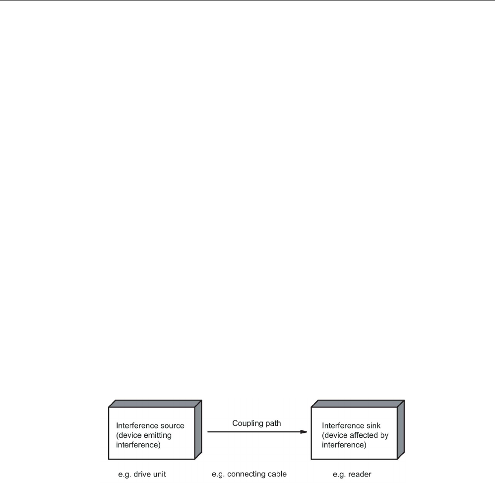
Planning the RF300 system
4.5 Guidelines for electromagnetic compatibility (EMC)
SIMATIC RF300
112 System Manual, 07/2017, C79000-G8976-C345-07
Shielding for the cables
● Shield the data cables and connect the shield at both ends.
● Shield the analog cables and connect the shield at one end, e.g. on the drive unit.
● Always apply large-area connections between the cable shields and the shielding bus at
the cabinet inlet and make the contact with clamps.
● Feed the connected shield through to the module without interruption.
● Use braided shields, not foil shields.
Line and signal filter
● Use only line filters with metal housings
● Connect the filter housing to the cabinet chassis using a large-area low-HF-impedance
connection.
● Never fix the filter housing to a painted surface.
● Fix the filter at the control cabinet inlet or in the direction of the source.
4.5.4
Propagation of electromagnetic interference
Three components have to be present for interference to occur in a system:
● Interference source
● Coupling path
● Interference sink
Figure 4-11 Propagation of interference
If one of the components is missing, e.g. the coupling path between the interference source
and the interference sink, the interference sink is unaffected, even if the interference source
is transmitting a high level of noise.

Planning the RF300 system
4.5 Guidelines for electromagnetic compatibility (EMC)
SIMATIC RF300
System Manual, 07/2017, C79000-G8976-C345-07 113
The EMC measures are applied to all three components, in order to prevent malfunctions
due to interference. When setting up a plant, the manufacturer must take all possible
measures in order to prevent the occurrence of interference sources:
● Only devices fulfilling limit class A of VDE 0871 may be used in a plant.
● Interference suppression measures must be introduced on all interference-emitting
devices. This includes all coils and windings.
● The design of the system must be such that mutual interference between individual
components is precluded or kept as small as possible.
Information and tips for plant design are given in the following sections.
Interference sources
In order to achieve a high level of electromagnetic compatibility and thus a very low level of
disturbance in a plant, it is necessary to recognize the most frequent interference sources.
These must then be eliminated by appropriate measures.
Table 4- 65 Interference sources: origin and effect
Interference source
Interference results from
Effect on the interference sink
Contactors,
electronic valves
Contacts
System disturbances
Coils Magnetic field
Electrical motor
Collector
Electrical field
Winding
Magnetic field
Electric welding device
Contacts
Electrical field
Transformer Magnetic field, system disturbance,
transient currents
Power supply unit, switched-
mode
Circuit Electrical and magnetic field, system
disturbance
High-frequency appliances
Circuit
Electromagnetic field
Transmitter
(e.g. service radio)
Antenna Electromagnetic field
Ground or reference potential
difference
Voltage difference Transient currents
Operator Static charge Electrical discharge currents, electrical
field
Power cable Current flow Electrical and magnetic field, system
disturbance
High-voltage cable
Voltage difference
Electrical field
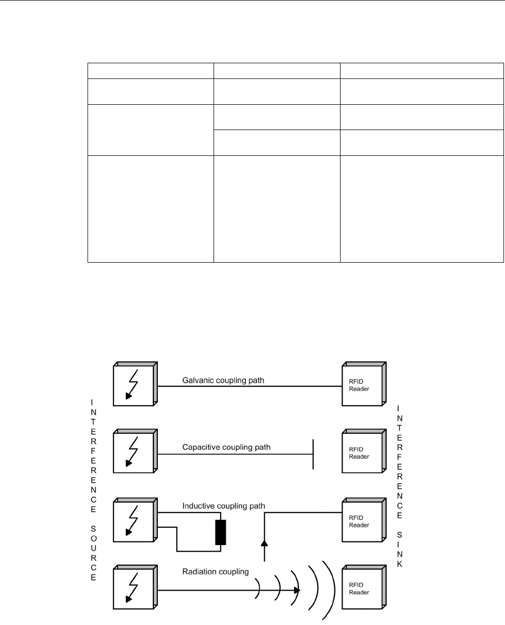
Planning the RF300 system
4.5 Guidelines for electromagnetic compatibility (EMC)
SIMATIC RF300
114 System Manual, 07/2017, C79000-G8976-C345-07
What interference can affect RFID?
Interference source
Cause
Remedy
Switched-mode power supply Interference emitted from the
current infeed
Replace the power supply
Interference injected through
the cables connected in
series
Cable is inadequately shield-
ed
Better cable shielding
The reader is not connected
to ground.
Ground the reader
HF interference over the
antennas
caused by another reader • Position the antennas further
apart.
• Erect suitable damping materials
between the antennas.
• Reduce the power of the readers.
Please follow the instructions in the
section
Installation guidelines/reducing
the effects of metal
Coupling paths
A coupling path has to be present before the disturbance emitted by the interference source
can affect the system. There are four ways in which interference can be coupled in:
Figure 4-12 Ways in which interference can be coupled in

Planning the RF300 system
4.5 Guidelines for electromagnetic compatibility (EMC)
SIMATIC RF300
System Manual, 07/2017, C79000-G8976-C345-07 115
When RFID modules are used, different components in the overall system can act as a
coupling path:
Table 4- 66 Causes of coupling paths
Coupling path
Invoked by
Conductors and cables • Incorrect or inappropriate installation
• Missing or incorrectly connected shield
• Inappropriate physical arrangement of cables
Control cabinet or housing • Missing or incorrectly wired equalizing conductor
• Missing or incorrect earthing
• Inappropriate physical arrangement
• Components not mounted securely
• Unfavorable cabinet configuration
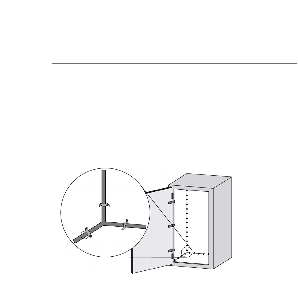
Planning the RF300 system
4.5 Guidelines for electromagnetic compatibility (EMC)
SIMATIC RF300
116 System Manual, 07/2017, C79000-G8976-C345-07
4.5.5
Cabinet configuration
The influence of the user in the configuration of an electromagnetically compatible plant
encompasses cabinet configuration, cable installation, ground connections and correct
shielding of cables.
Note
For information about electromagnetica
lly compatible cabinet configuration, please consult
the installation guidelines for SIMATIC PLCs.
Shielding by enclosure
Magnetic and electrical fields and electromagnetic waves can be kept away from the
interference sink by using a metal enclosure. The easier the induced interference current can
flow, the greater the intrinsic weakening of the interference field. All enclosures and metal
panels in the cabinet should therefore be connected in a manner allowing good
conductance.
Figure 4-13 Shielding by enclosure
If the control cabinet panels are insulated from each other, a high-frequency-conducting
connection can be established using ribbon cables and high-frequency terminals or HF
conducting paste. The larger the area of the connection, the greater the high-frequency
conductivity. This is not possible using single-wire connections.
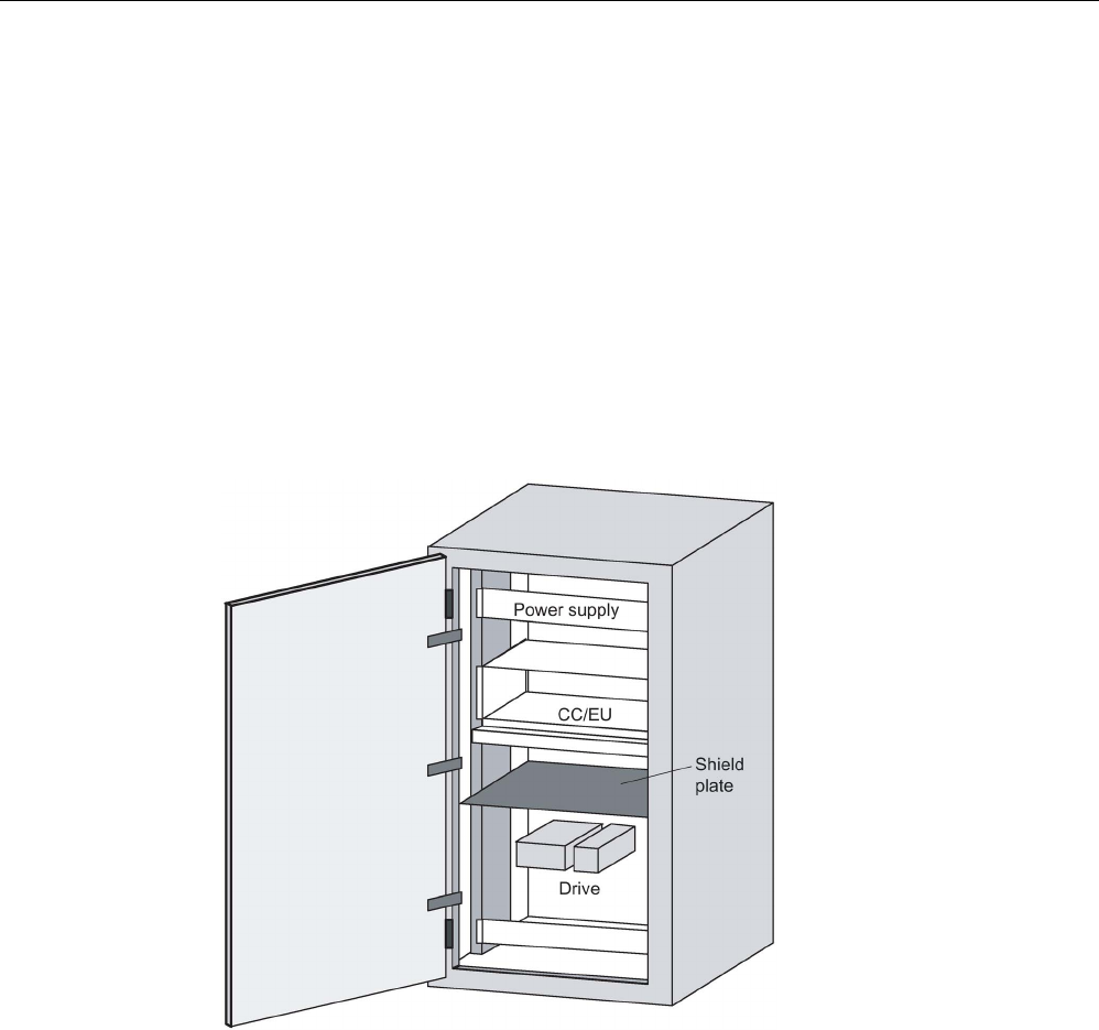
Planning the RF300 system
4.5 Guidelines for electromagnetic compatibility (EMC)
SIMATIC RF300
System Manual, 07/2017, C79000-G8976-C345-07 117
Prevention of interference by optimum configuration
Good interference suppression can be achieved by installing SIMATIC PLCs on conducting
mounting plates (unpainted). When setting up the control cabinet, interference can be
prevented easily by observing certain guidelines. Power components (transformers, drive
units, load power supply units) should be arranged separately from the control components
(relay control unit, SIMATIC S7).
As a rule:
● The effect of the interference decreases as the distance between the interference source
and interference sink increases.
● The interference can be further decreased by installing grounded shielding plates.
● The load connections and power cables should be installed separately from the signal
cables with a minimum clearance of 10 cm.
Figure 4-14 Prevention of interference by optimum configuration
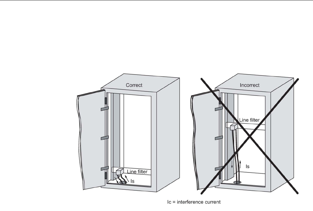
Planning the RF300 system
4.5 Guidelines for electromagnetic compatibility (EMC)
SIMATIC RF300
118 System Manual, 07/2017, C79000-G8976-C345-07
Filtering of the supply voltage
External interference from the mains can be prevented by installing line filters. Correct
installation is extremely important, in addition to appropriate dimensioning. It is essential that
the line filter is mounted directly at the cabinet inlet. As a result, interference is filtered
promptly at the inlet, and is not conducted through the cabinet.
Figure 4-15 Filtering of the supply voltage
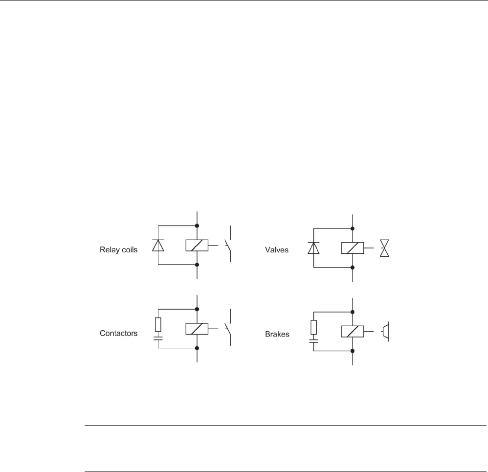
Planning the RF300 system
4.5 Guidelines for electromagnetic compatibility (EMC)
SIMATIC RF300
System Manual, 07/2017, C79000-G8976-C345-07 119
4.5.6
Prevention of interference sources
A high level of immunity to interference can be achieved by avoiding interference sources.
All switched inductances are frequent sources of interference in plants.
Suppression of inductance
Relays, contactors, etc. generate interference voltages and must therefore be suppressed
using one of the circuits below.
Even with small relays, interference voltages of up to 800 V occur on 24 V coils, and
interference voltages of several kV occur on 230 V coils when the coil is switched. The use
of freewheeling diodes or RC circuits prevents interference voltages and thus stray
interference on conductors installed parallel to the coil conductor.
Figure 4-16 Suppression of inductance
Note
All coils in the c
abinet should be suppressed. The valves and motor brakes are frequently
forgotten. Fluorescent lamps in the control cabinet should be tested in particular.
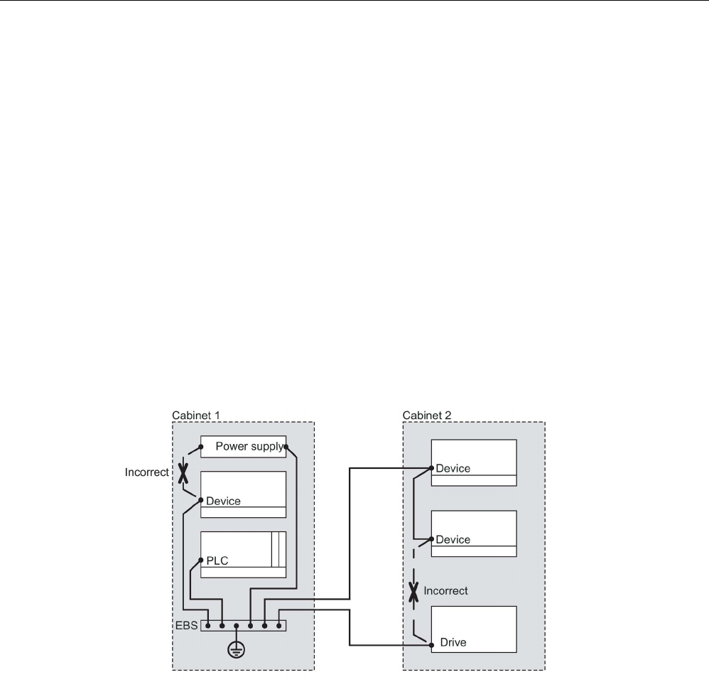
Planning the RF300 system
4.5 Guidelines for electromagnetic compatibility (EMC)
SIMATIC RF300
120 System Manual, 07/2017, C79000-G8976-C345-07
4.5.7
Equipotential bonding
Potential differences between different parts of a plant can arise due to the different design
of the plant components and different voltage levels. If the plant components are connected
across signal cables, transient currents flow across the signal cables. These transient
currents can corrupt the signals.
Proper equipotential bonding is thus essential.
● The equipotential bonding conductor must have a sufficiently large cross section (at least
10 mm2).
● The distance between the signal cable and the associated equipotential bonding
conductor must be as small as possible (antenna effect).
● A fine-strand conductor must be used (better high-frequency conductivity).
● When connecting the equipotential bonding conductors to the centralized equipotential
bonding strip (EBS), the power components and non-power components must be
combined.
● The equipotential bonding conductors of the separate modules must lead directly to the
equipotential bonding strip.
Figure 4-17 Equipotential bonding (EBS = Equipotential bonding strip)
The better the equipotential bonding in a plant, the smaller the chance of interference due to
fluctuations in potential.
Equipotential bonding should not be confused with protective earthing of a plant. Protective
earthing prevents the occurrence of excessive contact voltages in the event of equipment
faults whereas equipotential bonding prevents the occurrence of differences in potential.
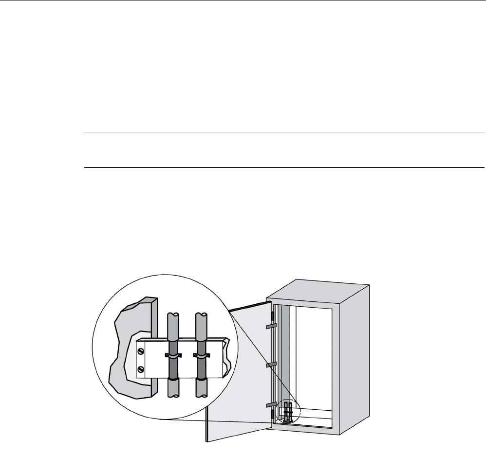
Planning the RF300 system
4.5 Guidelines for electromagnetic compatibility (EMC)
SIMATIC RF300
System Manual, 07/2017, C79000-G8976-C345-07 121
4.5.8
Cable shielding
Signal cables must be shielded in order to prevent coupling of interference.
The best shielding is achieved by installing the cables in steel tubes. However, this is only
necessary if the signal cable is routed through an environment prone to particular
interference. It is usually adequate to use cables with braided shields. In either case,
however, correct connection is vital for effective shielding.
Note
An unconnec
ted or incorrectly connected shield has no shielding effect.
As a rule:
● For analog signal cables, the shield should be connected at one end on the receiver side
● For digital signals, the shield should be connected to the enclosure at both ends
● Since interference signals are frequently within the HF range (> 10 kHz), a large-area HF-
proof shield contact is necessary
Figure 4-18 Cable shielding
The shielding bus should be connected to the control cabinet enclosure in a manner allowing
good conductance (large-area contact) and must be situated as close as possible to the
cable inlet. The cable insulation must be removed and the cable clamped to the shielding
bus (high-frequency clamp) or secured using cable ties. Care should be taken to ensure that
the connection allows good conductance.
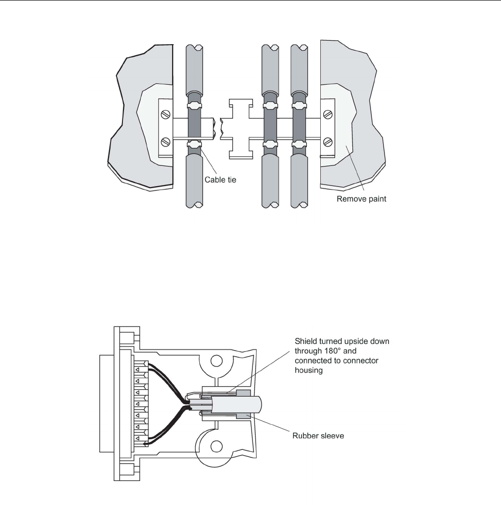
Planning the RF300 system
4.5 Guidelines for electromagnetic compatibility (EMC)
SIMATIC RF300
122 System Manual, 07/2017, C79000-G8976-C345-07
Figure 4-19 Connection of shielding bus
The shielding bus must be connected to the PE busbar.
If shielded cables have to be interrupted, the shield must be continued via the corresponding
connector housing. Only suitable connectors may be used for this purpose.
Figure 4-20 Interruption of shielded cables
If intermediate connectors, which do not have a suitable shield connection, are used, the
shield must be continued by fixing cable clamps at the point of interruption. This ensures a
large-area, HF-conducting contact.

SIMATIC RF300
System Manual, 07/2017, C79000-G8976-C345-07 123
Readers
5
Features of the RF300 reader
The reader provides inductive communication with the transponders and serial connection to
the communications modules.
Communication between the transponder and reader takes place over inductive alternating
fields.
The transmittable data volume between reader and transponder depends on
● the speed at which the transponder moves through the transmission window of the
reader.
● the length of the transmission window,
● the transponder type used (RF300- / ISO 15693- (MDS D)/ ISO 14443 transponder (MDS
E)),
● the memory type (FRAM, EEPROM; with RF300 transponders).
ISO 15693 functionality
With all readers of the RF300 family, you can use ISO 15693 transponders. Note that the
readers for RF300, ISO 15963 or ISO 14443 operation must have parameters assigned. The
parameter assignment done with the aid of the RESET frame (INIT-Run).
For more detailed information on software parameter assignment refer to the manuals.
● Function manual "Ident profile and Ident blocks
(https://support.industry.siemens.com/cs/ww/en/view/106368029)",
● Product Information "Input parameters for the RF300 system for programming via
communications modules
(https://support.industry.siemens.com/cs/ww/en/ps/15033/man)",
● Function manual "FB 45 (https://support.industry.siemens.com/cs/ww/en/view/21738808)"
as of version "AS ≥ A3".
ISO 14443 functionality
With all readers of the second generation of the RF300 family, you can use ISO 14443
transponders. The RF300 readers of the second generation therefore replace the MOBY E
readers SLG 72 and SLG 75. Note that the readers for RF300, ISO 15963 or ISO 14443
operation must have parameters assigned. The parameter assignment done with the aid of
the RESET frame (INIT-Run).
The following commands are supported in ISO 14443 operation of the readers:
● READ
● WRITE
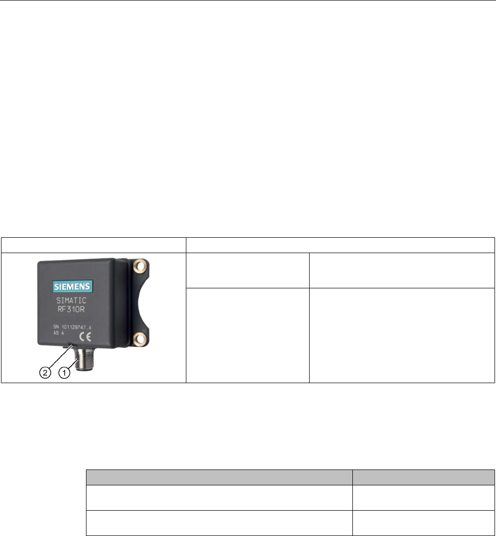
Readers
5.1 SIMATIC RF310R
SIMATIC RF300
124 System Manual, 07/2017, C79000-G8976-C345-07
● MDS-STATUS (mode 3)
● INIT
● REPEAT
Special ISO 14443 commands such as "INCREMENT", "DECREMENT" or "SET-VALUE"
are not supported.
5.1
SIMATIC RF310R
5.1.1
Features
SIMATIC RF310R
Characteristics
Design ① RS-422 interface
②
Status display
Area of application Identification tasks on small assembly lines
in harsh industrial environments
5.1.2
RF310R ordering data
Table 5- 1 RF310R ordering data
Article number
RF310R with RS-422 interface (3964R)
horizontal base plate
6GT2801-1AB10
RF310R with RS-422 interface (3964R)
base plate turned through 90°
6GT2801-1AB10-0AX1
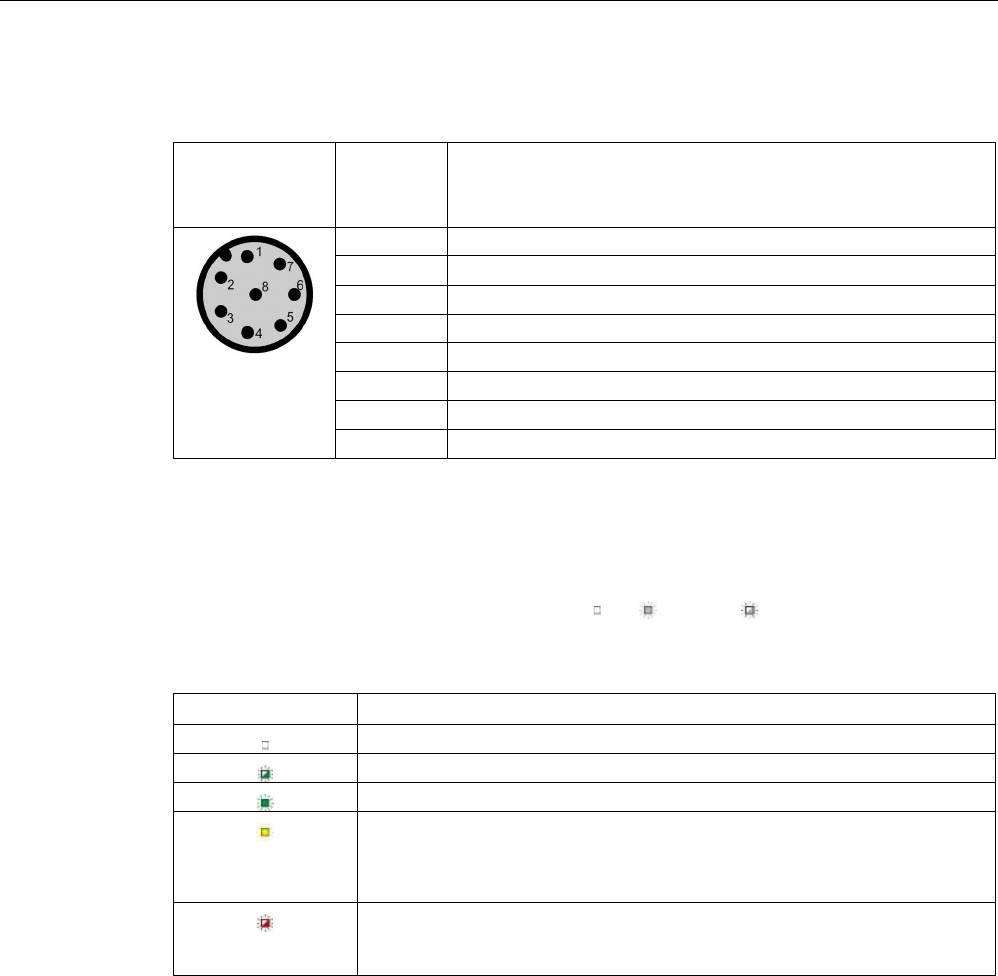
Readers
5.1 SIMATIC RF310R
SIMATIC RF300
System Manual, 07/2017, C79000-G8976-C345-07 125
5.1.3
Pin assignment RF310R with RS-422 interface
Pin
Pin
Device end
8-pin M12
Assignment
1
+ 24 V
2 - Transmit
3
0 V
4
+ Transmit
5
+ Receive
6
- Receive
7
Unassigned
8
Earth (shield)
5.1.4
LED operating display
The operational statuses of the reader are displayed by the LEDs. The LED can adopt the
colors green, red or yellow and the statuses off , on , flashing :
Table 5- 2 LED operating display on the reader
LED
Meaning
The reader is turned off.
Operating voltage present, reader not initialized or antenna switched off
Operating voltage present, reader initialized and antenna switched on
• Operating mode "with presence": Transponder present
• Operating mode "without presence": Transponder present and command
currently being executed
There is an error. The number of flashes provides information about the cur-
rent error. You will find more information on error messages in the section
"System diagnostics (Page 413)".
5.1.5
Ensuring reliable data exchange
The "center point" of the transponder must be situated within the transmission window.
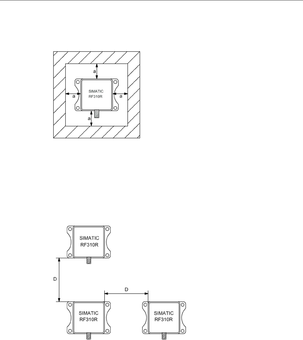
Readers
5.1 SIMATIC RF310R
SIMATIC RF300
126 System Manual, 07/2017, C79000-G8976-C345-07
5.1.6
Metal-free area
The RF310R can be flush-mounted in metal. Allow for a possible reduction in the field data.
Figure 5-1 Metal-free area for RF310R
To avoid any impact on the field data, the distance a should be ≥ 20 mm.
5.1.7
Minimum distance between RF310R readers
RF310R side by side
D
≥ 150 mm (with 2 readers)
D
≥ 200 mm (with more than 2 readers)
Figure 5-2 Minimum distance between RF310R readers

Readers
5.1 SIMATIC RF310R
SIMATIC RF300
System Manual, 07/2017, C79000-G8976-C345-07 127
RF310R face-of-face
D
≥ 300 mm
Figure 5-3 Face-of-face distance between two RF310Rs
5.1.8
Technical specifications
Table 5- 3 Technical specifications of the RF310R reader with RS-422 interface
6GT2801-1AB10
Product type designation
SIMATIC RF310R
Radio frequencies
Operating frequency, rated value
13.56 MHz
Electrical data
Maximum range
60 mm
Maximum data transmission speed
reader ↔ transponder
RF300 transponder ISO transponder
• Read • approx. 8000
bytes/s
• approx. 1500
bytes/s
• Write • approx. 8000
bytes/s
• approx. 1500
bytes/s
Transmission speed
19.2, 57.6, 115.2 kBd
Read/write distances of the reader See section "Field data for transponders, readers
and antennas (Page 51)."
MTBF (Mean Time Between Failures)
170 years
Interfaces
Electrical connector design
M12, 8-pin
Standard for interfaces for communication
RS-422
Antenna
integrated
Mechanical specifications
Enclosure
• Material • Plastic PA 12

Readers
5.1 SIMATIC RF310R
SIMATIC RF300
128 System Manual, 07/2017, C79000-G8976-C345-07
6GT2801-1AB10
• Color • Anthracite
Recommended distance to metal
0 mm
Supply voltage, current consumption, power loss
Supply voltage
24 VDC
Typical current consumption
50 mA
Permitted ambient conditions
Ambient temperature
• During operation • -25 to +70 ℃
• During transportation and storage • -40 to +85 ℃
Degree of protection to EN 60529
IP67
Shock-resistant to EN 60721-3-7, Class 7 M3
500 m/s
2
Vibration-resistant to EN 60721-3-7, Class 7 M3
200 m/s
2
Torsion and bending load
Not permitted
Design, dimensions and weights
Dimensions (L x W x H)
75 x 55 x 30 mm
Weight
200 g
Type of mounting 4 x M5 screw;
1.5 Nm
Cable length for RS-422 interface, maximum
1000 m
LED display design
3-color LED
Standards, specifications, approvals
Proof of suitability Radio to R&TTE directives EN 300330,
EN 301489, CE, FCC, UL/CSA

Readers
5.1 SIMATIC RF310R
SIMATIC RF300
System Manual, 07/2017, C79000-G8976-C345-07 129
5.1.9
Approvals
FCC information
Siemens SIMATIC RF310R (MLFB 6GT2801-1AB10); FCC ID NXW-RF310R
This device complies with part 15 of the FCC rules. Operation is subject to the following two
conditions:
(1) This device may not cause harmful interference, and
(2) this device must accept any interference received, including interference that may cause
undesired operation.
Caution
Any changes or modifications not expressly approved by the party responsible for
compliance could void the user's authority to operate the equipment.
Note
This equipment has been tested and found to comply with the limits for a Class A digital
device, pursuant to part 15 of the FCC Rules.
These limits are designed to provide reasonable protection against harmful interference
when the equipment is operated in a commercial environment. This equipment generates,
uses, and can radiate radio frequency energy and, if not installed and used in accordance
with the instruction manual, may cause harmful interference to radio communications.
Operation of this equipment in a residential area is likely to cause harmful interference in
which case the user will be required to correct the interference at his own expense.
IC information
This device complies with Industry Canada licence-exempt RSS standard(s). Operation is
subject to the following two conditions:
(1) This device may not cause interference, and
(2) this device must accept any interference, including interference that may cause
undesired operation of the device.
Le présent appareil est conforme aux CNR d`Industrie Canada applicables aux appareils
radio exempts de licence. L`exploitation est autorisée aux deux conditions suivantes :
(1) L`appareil ne doit pas produire de brouillage, et
(2) l'utilisateur de l`appareil doit accepter tout brouillage radioélectrique subi, même si le
brouillage est susceptible d`en compromettre le fonctionnement.
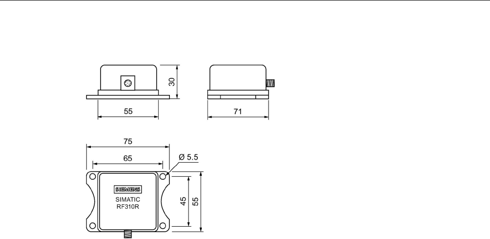
Readers
5.1 SIMATIC RF310R
SIMATIC RF300
130 System Manual, 07/2017, C79000-G8976-C345-07
5.1.10
Dimension drawing
Figure 5-4 Dimension drawing for RF310R
Dimensions in mm
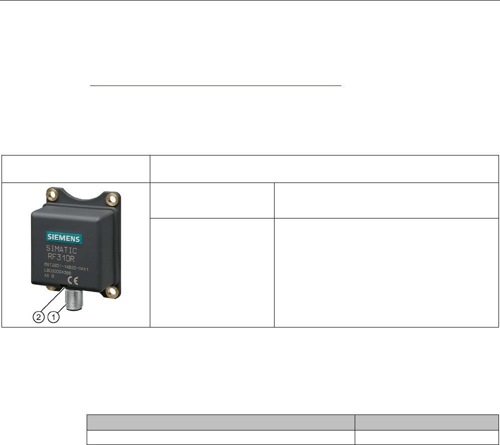
Readers
5.2 SIMATIC RF310R with Scanmode
SIMATIC RF300
System Manual, 07/2017, C79000-G8976-C345-07 131
5.2
SIMATIC RF310R with Scanmode
You will find detailed information on the SIMATIC RF310R with Scanmode on the Internet
(https://support.industry.siemens.com/cs/ww/en/ps/15034).
5.2.1
Features
SIMATIC RF310R special version
Scanmode
Characteristics
Design ① RS-422 interface
②
Status display
Area of application Identification tasks on small assembly lines in harsh
industrial environments
5.2.2
Ordering data for RF310R with Scanmode
Table 5- 4 Ordering data RF310R Scanmode
Article number
RF310R special version Scanmode with RS-422 interface
6GT2801-1AB20-0AX1
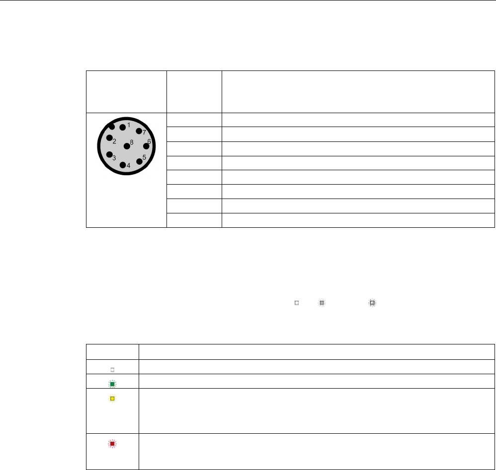
Readers
5.2 SIMATIC RF310R with Scanmode
SIMATIC RF300
132 System Manual, 07/2017, C79000-G8976-C345-07
5.2.3
Pin assignment RF310R special version Scanmode RS-422 interface
Pin
Pin
Device end
8-pin M12
Assignment
1
+ 24 V
2 - Transmit
3
0 V
4
+ Transmit
5
+ Receive
6
- Receive
7
Unassigned
8
Earth (shield)
5.2.4
LED operating display
The operational statuses of the reader are displayed by the LEDs. The LED can adopt the
colors green, red or yellow and the statuses off , on , flashing :
Table 5- 5 LED operating display on the reader
LED
Meaning
The reader is turned off.
Operating voltage present, reader ready for operation
• Operating mode "with presence": Transponder present
• Operating mode "without presence": Transponder present and command currently
being executed
There is an error. The number of flashes provides information about the current error.
You will find more information on error messages in the section "System diagnostics
(Page 413)".
5.2.5
Ensuring reliable data exchange
The "center point" of the transponder must be situated within the transmission window.
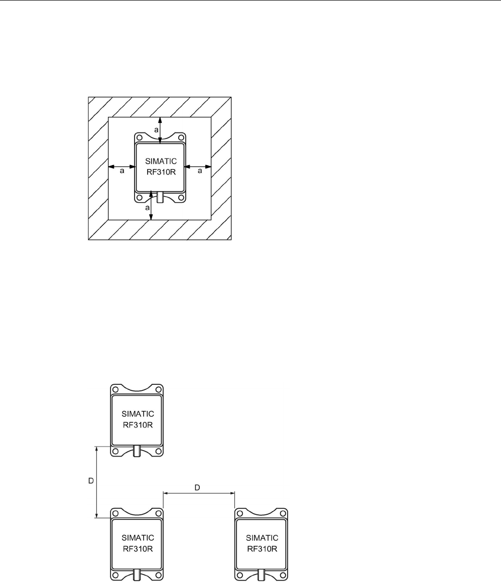
Readers
5.2 SIMATIC RF310R with Scanmode
SIMATIC RF300
System Manual, 07/2017, C79000-G8976-C345-07 133
5.2.6
Metal-free area
The RF310R special version can be flush-mounted in metal. Allow for a possible reduction in
the field data.
Figure 5-5 Metal-free area for RF310R special version
To avoid any impact on the field data, the distance a should be ≥ 20 mm.
5.2.7
Minimum distance between several readers
RF310R special version side by side
D
≥ 150 mm (with 2 readers)
D
≥ 200 mm (with more than 2 readers)
Figure 5-6 Minimum distance between RF310R readers

Readers
5.2 SIMATIC RF310R with Scanmode
SIMATIC RF300
134 System Manual, 07/2017, C79000-G8976-C345-07
RF310R special version face-to-face
D
≥ 300 mm
Figure 5-7 Face-to-face distance between two RF310R special version
5.2.8
Technical specifications
Table 5- 6 Technical specifications of the RF310R reader with Scanmode
6GT2801-1AB20-0AX1
Product type designation
SIMATIC RF310R Scanmode
Radio frequencies
Operating frequency, rated value
13.56 MHz
Electrical data
Maximum range
60 mm
Maximum data transmission speed
reader ↔ transponder
RF300 transponder ISO transponder
• Read • approx. 8000
bytes/s
• approx. 1500
bytes/s
Transmission speed
9.6, 19.2, 38.4, 57.6, 115.2 kBd
Read/write distances of the reader See section "Field data for transponders, readers
and antennas (Page 51)."
MTBF (Mean Time Between Failures)
170 years
Interfaces
Electrical connector design
M12, 8-pin
Standard for interfaces for communication
RS-422 (Scanmode)
Antenna
integrated
Mechanical specifications
Enclosure
• Material • Plastic PA 12
• Color • Anthracite
Recommended distance to metal
0 mm

Readers
5.2 SIMATIC RF310R with Scanmode
SIMATIC RF300
System Manual, 07/2017, C79000-G8976-C345-07 135
6GT2801-1AB20-0AX1
Supply voltage, current consumption, power loss
Supply voltage
24 VDC
Typical current consumption
50 mA
Permitted ambient conditions
Ambient temperature
• During operation • -25 to +70 ℃
• During transportation and storage • -40 to +85 ℃
Degree of protection to EN 60529
IP67
Shock-resistant to EN 60721-3-7, Class 7 M3
500 m/s
2
Vibration-resistant to EN 60721-3-7, Class 7 M3
200 m/s
2
Torsion and bending load
Not permitted
Design, dimensions and weights
Dimensions (L x W x H)
75 x 55 x 30 mm
Weight
170 g
Type of mounting 4 x M5 screws;
1.5 Nm
Cable length for RS-422 interface, maximum
1000 m
LED display design
3-color LED
Standards, specifications, approvals
Proof of suitability Radio to R&TTE directives EN 300330,
EN 301489, CE, FCC, UL/CSA
5.2.9
Approvals
FCC information
Siemens SIMATIC RF310R (MLFB 6GT2801-1AB20-0AX1); FCC ID NXW-RF310R
This device complies with part 15 of the FCC rules. Operation is subject to the following two
conditions:
(1) This device may not cause harmful interference, and
(2) this device must accept any interference received, including interference that may cause
undesired operation.
Caution
Any changes or modifications not expressly approved by the party responsible for
compliance could void the user's authority to operate the equipment.
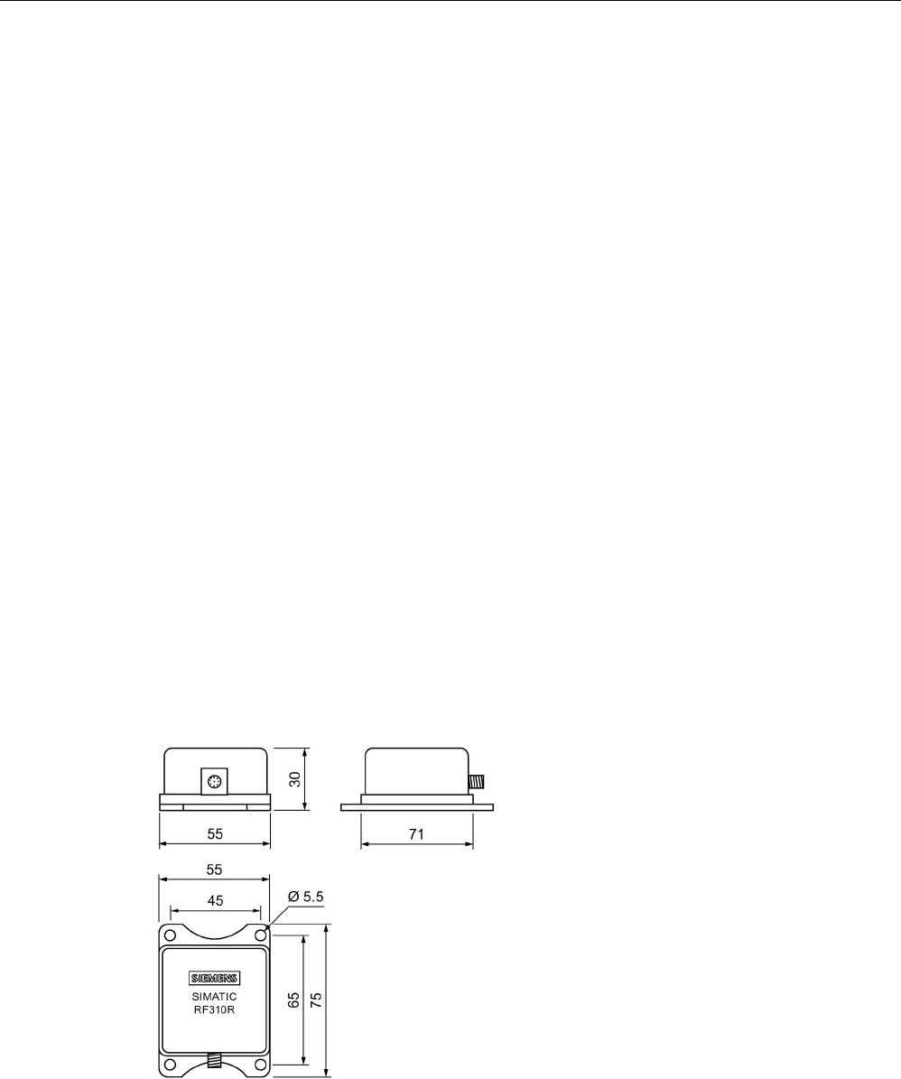
Readers
5.2 SIMATIC RF310R with Scanmode
SIMATIC RF300
136 System Manual, 07/2017, C79000-G8976-C345-07
Note
This equipment has been tested and found to comply with the limits for a Class A digital
device, pursuant to part 15 of the FCC Rules.
These limits are designed to provide reasonable protection against harmful interference
when the equipment is operated in a commercial environment. This equipment generates,
uses, and can radiate radio frequency energy and, if not installed and used in accordance
with the instruction manual, may cause harmful interference to radio communications.
Operation of this equipment in a residential area is likely to cause harmful interference in
which case the user will be required to correct the interference at his own expense.
IC information
This device complies with Industry Canada licence-exempt RSS standard(s). Operation is
subject to the following two conditions:
(1) This device may not cause interference, and
(2) this device must accept any interference, including interference that may cause
undesired operation of the device.
Le présent appareil est conforme aux CNR d`Industrie Canada applicables aux appareils
radio exempts de licence. L`exploitation est autorisée aux deux conditions suivantes :
(1) L`appareil ne doit pas produire de brouillage, et
(2) l'utilisateur de l`appareil doit accepter tout brouillage radioélectrique subi, même si le
brouillage est susceptible d`en compromettre le fonctionnement.
5.2.10
Dimension drawing
Figure 5-8 Dimension drawing RF310R special version Scanmode
Dimensions in mm
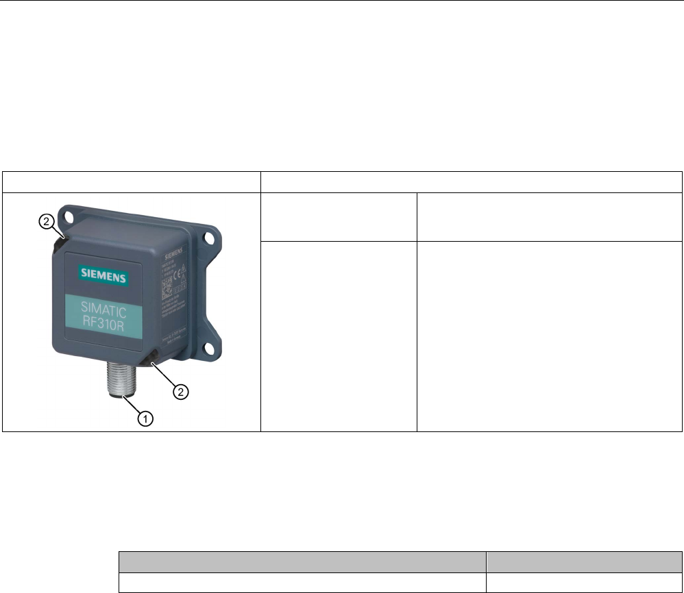
Readers
5.3 SIMATIC RF310R - 2nd generation
SIMATIC RF300
System Manual, 07/2017, C79000-G8976-C345-07 137
5.3
SIMATIC RF310R - 2nd generation
5.3.1
Features
SIMATIC RF310R
Characteristics
Design ① RS-422 interface
②
LED operating display
Area of application Identification tasks on small assembly lines in
harsh industrial environments
5.3.2
Ordering data
Table 5- 7 RF310R ordering data
Article number
RF310R with RS-422 interface (3964R)
6GT2801-1BA10
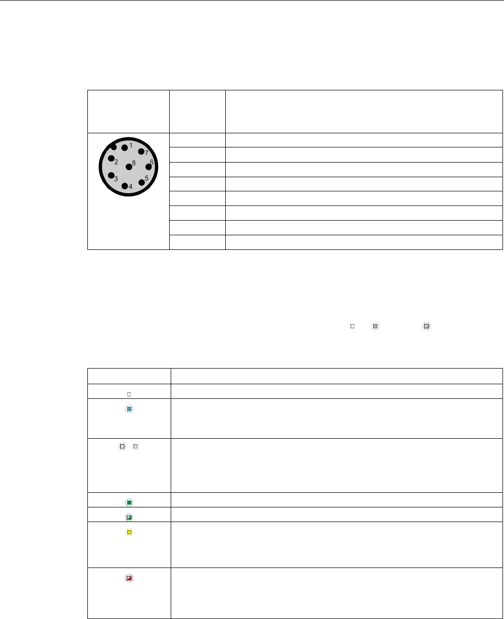
Readers
5.3 SIMATIC RF310R - 2nd generation
SIMATIC RF300
138 System Manual, 07/2017, C79000-G8976-C345-07
5.3.3
Pin assignment of the RS-422 interface
Table 5- 8 Pin assignment
Pin
Pin
Device end
8-pin M12
Assignment
1
+ 24 V
2 - Transmit
3
0 V
4
+ Transmit
5
+ Receive
6
- Receive
7
Unassigned
8
Earth (shield)
5.3.4
LED operating display
The operational statuses of the reader are displayed by two LEDs. The LEDs can adopt the
colors white green, red, yellow or blue and the statuses off , on , flashing :
Table 5- 9 Display elements
LED
Meaning
The reader is turned off.
The reader is turned on and is searching for transponders.
The reader is in the "Setup" mode, in the "Search for transponders" status and
has not yet received a "RESET" command and is not ready.
/ There is transponder in the antenna field.
The reader is in the "Setup" mode, in the status "Show quality", has not yet re-
ceived a "RESET" command and is not ready.
Depending on the signal strength, the LED flickers or is lit permanently.
The reader has received a "RESET" command.
The reader is turned on, the antenna is turned off.
• Operating mode "with presence": Transponder present
• Operating mode "without presence": Transponder present and command
currently being executed
There is an error. The number of flashes provides information about the current
error.
You will find more information on error messages in the section "System diag-
nostics (Page 413)".
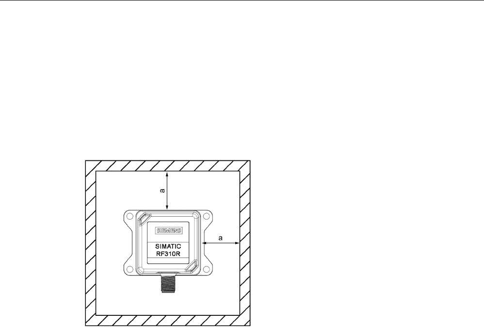
Readers
5.3 SIMATIC RF310R - 2nd generation
SIMATIC RF300
System Manual, 07/2017, C79000-G8976-C345-07 139
5.3.5
Ensuring reliable data exchange
The "center point" of the transponder must be situated within the transmission window.
5.3.6
Metal-free area
The RF310R can be flush-mounted in metal. Allow for a possible reduction in the field data.
To avoid any influence on the field data, the distance "a" should be kept to.
a ≥
20 mm
Figure 5-9 Metal-free area for RF310R
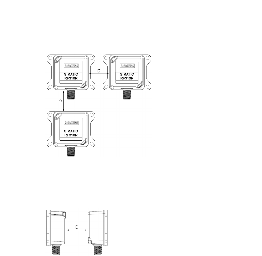
Readers
5.3 SIMATIC RF310R - 2nd generation
SIMATIC RF300
140 System Manual, 07/2017, C79000-G8976-C345-07
5.3.7
Minimum distance between RF310R readers
RF310R side by side
D ≥
150 mm (with 2 readers)
D ≥
200 mm (with more than 2 readers)
Figure 5-10 Minimum distance between RF310R readers
RF310R face-of-face
D ≥
300 mm
Figure 5-11 Face-of-face distance between two RF310Rs

Readers
5.3 SIMATIC RF310R - 2nd generation
SIMATIC RF300
System Manual, 07/2017, C79000-G8976-C345-07 141
5.3.8
Technical specifications
Table 5- 10 Technical specifications of the RF310R reader with RS-422 interface
6GT2801-1BA10
Product type designation
SIMATIC RF310R
Radio frequencies
Operating frequency, rated value
13.56 MHz
Electrical data
Maximum range
60 mm
Maximum data transmission speed
reader ↔ transponder
RF300
transponder
ISO
transponder
(MDS D)
ISO tran-
sponder
(MDS E)
• Read • ≤ 8000
bytes/s
• ≤ 3300
bytes/s
• ≤ 3400
bytes/s
• Write • ≤ 8000
bytes/s
• ≤ 1700
bytes/s
• ≤ 800
bytes/s
Transmission speed
19.2, 57.6, 115.2 kBd
Read/write distances of the reader See section "Field data for transponders, readers
and antennas (Page 51)."
MTBF (Mean Time Between Failures)
273 years
Interfaces
Electrical connector design
M12, 8-pin
Standard for interfaces for communication
RS-422
Antenna
integrated
Mechanical specifications
Enclosure
• Material • Plastic PA 12
• Color • TI-Grey
Recommended distance to metal
0 mm
Supply voltage, current consumption, power loss
Supply voltage
24 VDC
Typical current consumption
60 mA
Permitted ambient conditions
Ambient temperature
• During operation • -25 to +70 ℃

Readers
5.3 SIMATIC RF310R - 2nd generation
SIMATIC RF300
142 System Manual, 07/2017, C79000-G8976-C345-07
6GT2801-1BA10
• During transportation and storage • -40 to +85 ℃
Degree of protection to EN 60529
IP67
Shock-resistant to EN 60721-3-7, Class 7 M3
500 m/s
2
Vibration-resistant to EN 60721-3-7, Class 7 M3
200 m/s
2
Torsion and bending load
Not permitted
Design, dimensions and weights
Dimensions (L x W x H)
75 x 55 x 30 mm
Weight
100 g
Type of mounting 4 x M5 screws;
1.5 Nm
Cable length for RS-422 interface, maximum
1000 m
LED display design
2 LEDs, 5 colors
Standards, specifications, approvals
Proof of suitability Radio to R&TTE directives EN 300330,
EN 301489, CE, FCC, UL/CSA (IEC 61010),
Ex approval
5.3.9
Approvals
FCC information
Siemens SIMATIC RF310R (MLFB 6GT2801-1BA10); FCC ID NXW-RF310R02
This device complies with part 15 of the FCC rules. Operation is subject to the following two
conditions:
(1) This device may not cause harmful interference, and
(2) this device must accept any interference received, including interference that may cause
undesired operation.
Caution
Any changes or modifications not expressly approved by the party responsible for
compliance could void the user's authority to operate the equipment.
Note
This equipment has been tested and found to comply with the limits for a Class A digital
device, pursuant to part 15 of the FCC Rules.
These limits are designed to provide reasonable protection against harmful interference
when the equipment is operated in a commercial environment. This equipment generates,
uses, and can radiate radio frequency energy and, if not installed and used in accordance
with the instruction manual, may cause harmful interference to radio communications.

Readers
5.3 SIMATIC RF310R - 2nd generation
SIMATIC RF300
System Manual, 07/2017, C79000-G8976-C345-07 143
Operation of this equipment in a residential area is likely to cause harmful interference in
which case the user will be required to correct the interference at his own expense.
IC information
This device complies with Industry Canada licence-exempt RSS standard(s). Operation is
subject to the following two conditions:
(1) This device may not cause interference, and
(2) this device must accept any interference, including interference that may cause
undesired operation of the device.
Le présent appareil est conforme aux CNR d`Industrie Canada applicables aux appareils
radio exempts de licence. L`exploitation est autorisée aux deux conditions suivantes :
(1) L`appareil ne doit pas produire de brouillage, et
(2) l'utilisateur de l`appareil doit accepter tout brouillage radioélectrique subi, même si le
brouillage est susceptible d`en compromettre le fonctionnement.
UL information (IEC 61010-1 / IEC 61010-2-201)
This standard applies to equipment designed to be safe at least under the following
conditions:
● a) indoor use;
● b) altitude up to 2 000 m;
● c) temperature -25 °C to 70 °C;
● d) maximum relative humidity 80 % for temperature up to 31 °C decreasing linearly to 50
% relative humidity at 40 °C;
● e) TRANSIENT OVERVALTAGES up to the levels of OVERVALTAGE CATEGORY II,
NOTE 1: These levels of transient overvoltage are typical for equipment supplied from the
building wiring.
● f) using a "NEC Class 2" power supply is required
● g) the device is categorized as pollution degree 3/4
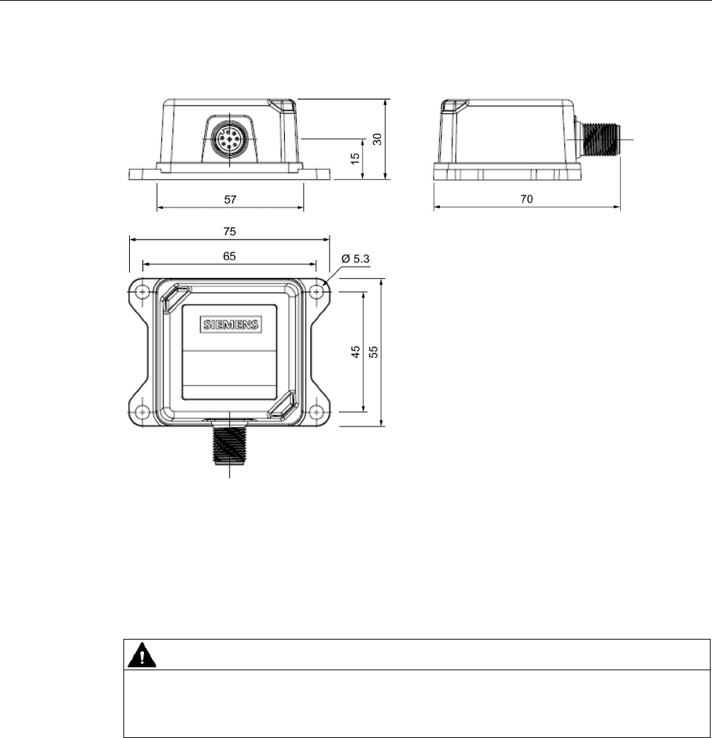
Readers
5.3 SIMATIC RF310R - 2nd generation
SIMATIC RF300
144 System Manual, 07/2017, C79000-G8976-C345-07
5.3.10
Dimension drawing
Figure 5-12 Dimension drawing for RF310R
Dimensions in mm
5.3.11
Using the reader in hazardous area
WARNING
Explosion hazard
In a flammable or combustible environment, no cables may be connected to or
disconnected from the device.
Readers
5.3 SIMATIC RF310R - 2nd generation
SIMATIC RF300
System Manual, 07/2017, C79000-G8976-C345-07 145
ATEX
The SIMATIC Ident products meet the requirements of explosion protection acc. to ATEX.
The products meet the requirements of the standards:
Document
Title
EN 60079-0 Hazardous areas
Part 0: Equipment - General requirements
EN 60079-7 Hazardous areas
Part 7: Equipment protection by increased safety "e"
EN 60079-31 Potentially explosive atmosphere
Part 31: Equipment dust ignition protection by enclosure "t"
You will find the current versions of the standards in the currently valid ATEX certificates.
ATEX mark
NOTICE
Validity only when the devices are marked
There is a corresponding approval only with devices to which the Ex mark is applied.
The identification of the electrical equipment as an enclosed unit is:
II 3 G Ex ec IIB T4 Gc
II 3 D Ex tc IIIC T80°C
Dc
-25 °C ... +70 °C
U
n
= 24 VDC
The equipment also has the following additional information:
XXXYYYZZZ
[= serial number, is assigned during production]
DEMKO 17 ATEX 1767 X
[= certificate number]

Readers
5.3 SIMATIC RF310R - 2nd generation
SIMATIC RF300
146 System Manual, 07/2017, C79000-G8976-C345-07
IECEx
The SIMATIC Ident products meet the requirements of explosion protection acc. to IECEx.
The products meet the requirements of the standards:
Document
Title
IEC 60079-0 Hazardous areas
Part 0: Equipment - General requirements
IEC 60079-7 Hazardous areas
Part 7: Equipment protection by increased safety "e"
IEC 60079-31 Potentially explosive atmosphere
Part 31: Equipment dust ignition protection by enclosure "t"
You will find the current versions of the standards in the currently valid IECEx certificates.
IECEx mark
NOTICE
Validity only when the devices are marked
There is a corresponding approval only with devices to which the IECEx mark is applied.
The identification of the electrical equipment as an enclosed unit is:
II 3 G Ex ec IIB T4 Gc
II 3 D Ex tc IIIC T80°C Dc
-25 °C ... +70 °C
U
n= 24 VDC
The equipment also has the following additional information:
XXXYYYZZZ
[= serial number, is assigned during production]
IECEx ULD 17.0031 X
[= certificate number]
Readers
5.3 SIMATIC RF310R - 2nd generation
SIMATIC RF300
System Manual, 07/2017, C79000-G8976-C345-07 147
UL HAZ. LOC.
The SIMATIC Ident products meet the requirements of explosion protection acc. to UL HAZ.
LOC. The products meet the requirements of the standards:
Document
Title
UL 60079-0
Hazardous areas
Part 0: Equipment - General requirements
CSA C22.2 NO. 60079-0
UL 60079-7
Hazardous areas
Part 7: Equipment protection by increased safety "e"
CSA C22.2 NO. 60079-7
UL 60079-31
Potentially explosive atmosphere
Part 31: Equipment dust ignition protection by enclosure "t"
CSA C22.2 NO. 60079-31
You will find the current versions of the standards in the currently valid UL HAZ. LOC.
certificates
UL HAZ. LOC. mark
NOTICE
Validity only when the devices are marked
There is a corresponding approval only with devices to which the UL HAZ. LOC. mark is
applied.
The identification of the electrical equipment as an enclosed unit is:
E223122
IND.CONT.EQ FOR HAZ.LOC.
CL.I, DIV.2, GP.C,D T4
CL.II, DIV.2, GP.F,G T80°C
AEx ec IIB T4, Ex ec IIB T4
AEx tc IIIC T80°C, Ex tc IIIC T80°C
-25 °C ... +70 °C
U
n
= 24 VDC
The equipment also has the following additional information:
XXXYYYZZZ
[= serial number, is assigned during production]
Readers
5.3 SIMATIC RF310R - 2nd generation
SIMATIC RF300
148 System Manual, 07/2017, C79000-G8976-C345-07
5.3.11.1
Using the reader in hazardous area for gases
The temperature class of the reader for hazardous areas depends on the ambient
temperature range:
Ambient temperature range
Temperature class
-25 ℃ ... +70 ℃
T4
WARNING
Ignitions of gas-air mixtures
When using the reader, check to make sure that the temperature class is adhered to in
keeping with the requirements of the area of application
Non-compliance with the permitted temperature ranges while using the reader can lead to
ignitions of gas-air mixtures.
5.3.11.2
Using the reader in hazardous area for dust
The equipment is suitable for dusts whose ignition temperatures for a dust layer of 5 mm are
higher than 80 °C (smoldering temperature).
Ambient temperature range
Temperature value
-25 °C < Ta < +70 °C
T80 °C
WARNING
Ignitions of dust-air mixtures
When using the reader, check to make sure that the temperature values are adhered to in
keeping with the requirements of the area of application. Non-
compliance with the permitted
temperature range while using the reader can lead to ignitions of dust-air mixtures.

Readers
5.3 SIMATIC RF310R - 2nd generation
SIMATIC RF300
System Manual, 07/2017, C79000-G8976-C345-07 149
5.3.11.3
Installation and operating conditions for hazardous areas:
NOTICE
Risk of explosion
Risk of explosion of dust-air mixtures or gas-air mixtures and the device can be damaged.
Note the following conditions when installing and operating the device in a hazardous area:
• Making and breaking of circuits is permitted only in a de-energized state.
• The maximum surface temperature, corresponding to the marking, applies only for
operation without a cover of dust.
• The device may only be operated in such a way that adequate protection against UV
light is ensured.
• The device may not be operated in areas influenced by processes that generate high
electrostatic charges.
• The device must be installed so that it is mechanically protected.
• The grounding of the plug (8-pin) on the reader must be via its supply cable.
• The device may only be operated with accessories specified or supplied by the
manufacturer. All the points above also apply to the accessories (cables and
connectors) and to the antennas (exception: the housing of ANT 1 does not need to be
installed with impact protection).
• The device sockets incl. the metal parts of the connecting cable must have a shrink-on
sleeve pulled over them, in other words, all metal parts apart from the securing sockets
of the housing must be fully covered and be inaccessible.
• After disconnecting the connections (antenna cable, signal/supply cable), before the
plugs are inserted again, they must be checked for contamination and if necessary
cleaned.
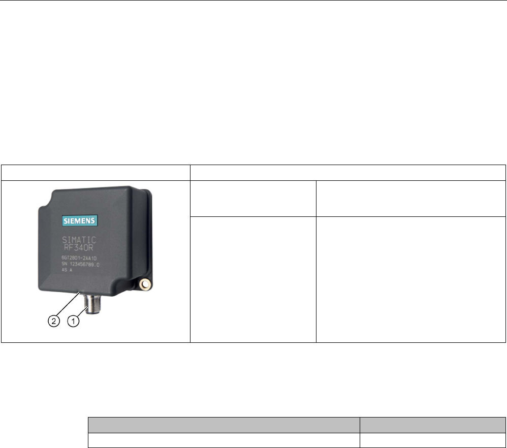
Readers
5.4 SIMATIC RF340R/RF350R
SIMATIC RF300
150 System Manual, 07/2017, C79000-G8976-C345-07
5.4
SIMATIC RF340R/RF350R
5.4.1
SIMATIC RF340R
5.4.1.1
Features
SIMATIC RF340R
Characteristics
Design ① RS-422 interface
②
Status display
Area of application Identification tasks on assembly lines in
harsh industrial environments
5.4.1.2
Ordering data for RF340R
Table 5- 11 Ordering data for RF340R
Article number
RF340R with RS-422 interface (3964R)
6GT2801-2AB10
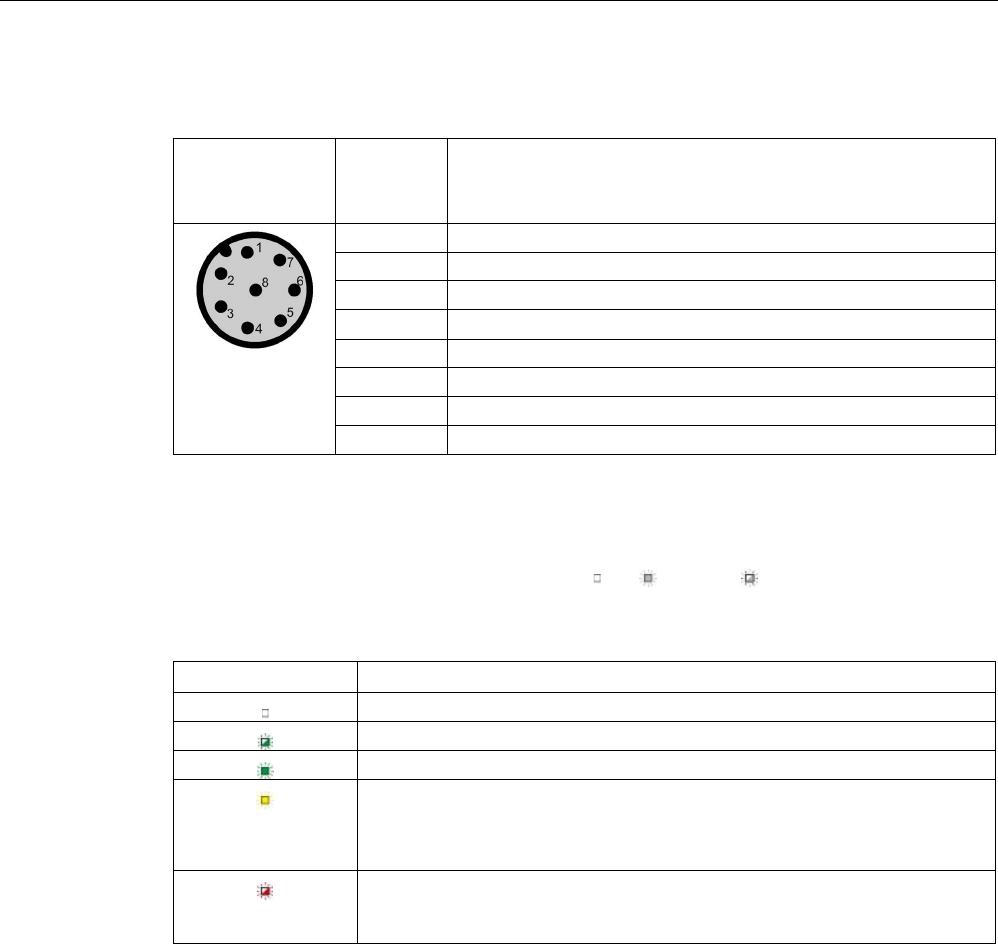
Readers
5.4 SIMATIC RF340R/RF350R
SIMATIC RF300
System Manual, 07/2017, C79000-G8976-C345-07 151
5.4.1.3
Pin assignment of RF340R RS422 interface
Pin
Pin
Device end
8-pin M12
Assignment
1
+ 24 V
2
- Transmit
3
0 V
4 + Transmit
5
+ Receive
6
- Receive
7
Unassigned
8
Earth (shield)
5.4.1.4
LED operating display
The operational statuses of the reader are displayed by the LEDs. The LED can adopt the
colors green, red or yellow and the statuses off , on , flashing :
Table 5- 12 LED operating display on the reader
LED
Meaning
The reader is turned off.
Operating voltage present, reader not initialized or antenna switched off
Operating voltage present, reader initialized and antenna switched on
• Operating mode "with presence": Transponder present
• Operating mode "without presence": Transponder present and command
currently being executed
There is an error. The number of flashes provides information about the cur-
rent error. You will find more information on error messages in the section
"System diagnostics (Page 413)".
5.4.1.5
Ensuring reliable data exchange
The "center point" of the transponder must be situated within the transmission window.
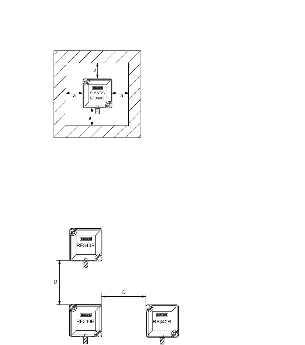
Readers
5.4 SIMATIC RF340R/RF350R
SIMATIC RF300
152 System Manual, 07/2017, C79000-G8976-C345-07
5.4.1.6
Metal-free area
The RF340R can be flush-mounted in metal. Allow for a possible reduction in the field data.
Figure 5-13 Metal-free area for RF340R
To avoid any impact on the field data, the distance a should be ≥ 20 mm.
5.4.1.7
Minimum distance between RF340R readers
RF340R side by side
D
≥ 200 mm (with 2 readers)
D
≥ 250 mm (with more than 2 readers)
Figure 5-14 Minimum distance between RF340R readers

Readers
5.4 SIMATIC RF340R/RF350R
SIMATIC RF300
System Manual, 07/2017, C79000-G8976-C345-07 153
RF340R face-of-face
D
≥ 500 mm
Figure 5-15 Face-of-face distance between two RF340Rs
5.4.1.8
Technical specifications
Table 5- 13 Technical specifications of the RF340R reader
6GT2801-2AB10
Product type designation
SIMATIC RF340R
Radio frequencies
Operating frequency, rated value
13.56 MHz
Electrical data
Maximum range
140 mm
Maximum data transmission speed
reader ↔ transponder
RF300 transponder ISO transponder
• Read • approx. 8000
bytes/s
• approx. 1500
bytes/s
• Write • approx. 8000
bytes/s
• approx. 1500
bytes/s
Transmission speed
19.2, 57.6, 115.2 kBd
Read/write distances of the reader See section "Field data for transponders, readers
and antennas (Page 51)."
MTBF (Mean Time Between Failures)
140 years
Interfaces
Electrical connector design
M12, 8-pin
Standard for interfaces for communication
RS-422 (3964R protocol)
Antenna
integrated
Mechanical specifications
Enclosure
• Material • Plastic PA 12

Readers
5.4 SIMATIC RF340R/RF350R
SIMATIC RF300
154 System Manual, 07/2017, C79000-G8976-C345-07
6GT2801-2AB10
• Color • Anthracite
Recommended distance to metal
0 mm
Supply voltage, current consumption, power loss
Supply voltage
24 VDC
Typical current consumption
100 mA
Permitted ambient conditions
Ambient temperature
• During operation • -25 to +70 ℃
• During transportation and storage • -40 to +85 ℃
Degree of protection to EN 60529
IP67
Shock-resistant to EN 60721-3-7, Class 7 M3
500 m/s
2
Vibration-resistant to EN 60721-3-7, Class 7 M3
200 m/s
2
Torsion and bending load
Not permitted
Design, dimensions and weights
Dimensions (L x W x H)
75 x 75 x 41 mm
Weight
250 g
Type of mounting 2 x M5 screws;
1.5 Nm
Cable length for RS-422 interface, maximum
1000 m
LED display design
3-color LED
Standards, specifications, approvals
Proof of suitability Radio to R&TTE directives EN 300330,
EN 301489, CE, FCC, UL/CSA,
Ex approval

Readers
5.4 SIMATIC RF340R/RF350R
SIMATIC RF300
System Manual, 07/2017, C79000-G8976-C345-07 155
5.4.1.9
Approvals
FCC information
Siemens SIMATIC RF340R (MLFB 6GT2801-2AA10); FCC ID NXW-RF340R
Siemens SIMATIC RF340R (MLFB 6GT2801-2AB10); FCC ID NXW-RF340R01
This device complies with part 15 of the FCC rules. Operation is subject to the following two
conditions:
(1) This device may not cause harmful interference, and
(2) this device must accept any interference received, including interference that may cause
undesired operation.
Caution
Any changes or modifications not expressly approved by the party responsible for
compliance could void the user's authority to operate the equipment.
Note
This equipment has been tested and found to comply with the limits for a Class A digital
device, pursuant to part 15 of the FCC Rules.
These limits are designed to provide reasonable protection against harmful interference
when the equipment is operated in a commercial environment. This equipment generates,
uses, and can radiate radio frequency energy and, if not installed and used in accordance
with the instruction manual, may cause harmful interference to radio communications.
Operation of this equipment in a residential area is likely to cause harmful interference in
which case the user will be required to correct the interference at his own expense.
IC information
This device complies with Industry Canada licence-exempt RSS standard(s). Operation is
subject to the following two conditions:
(1) This device may not cause interference, and
(2) this device must accept any interference, including interference that may cause
undesired operation of the device.
Le présent appareil est conforme aux CNR d`Industrie Canada applicables aux appareils
radio exempts de licence. L`exploitation est autorisée aux deux conditions suivantes :
(1) L`appareil ne doit pas produire de brouillage, et
(2) l'utilisateur de l`appareil doit accepter tout brouillage radioélectrique subi, même si le
brouillage est susceptible d`en compromettre le fonctionnement.
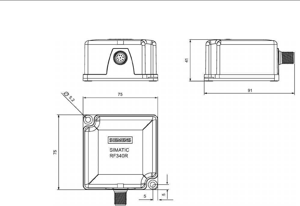
Readers
5.4 SIMATIC RF340R/RF350R
SIMATIC RF300
156 System Manual, 07/2017, C79000-G8976-C345-07
5.4.1.10
Dimension drawing
Figure 5-16 Dimension drawing for RF340R
Dimensions in mm