Siemens RF380R02 RFID Reader 13.56 MHz User Manual SIMATIC RF300
Siemens AG RFID Reader 13.56 MHz SIMATIC RF300
Siemens >
Contents
- 1. SYH_RF300_76_Part 1
- 2. SYH_RF300_76_Part 2
- 3. SYH_RF300_76_Part 3
SYH_RF300_76_Part 2
Readers
5.4 SIMATIC RF340R/RF350R
SIMATIC RF300
System Manual, 07/2017, C79000-G8976-C345-07 157
5.4.2
SIMATIC RF350R
5.4.2.1
Features
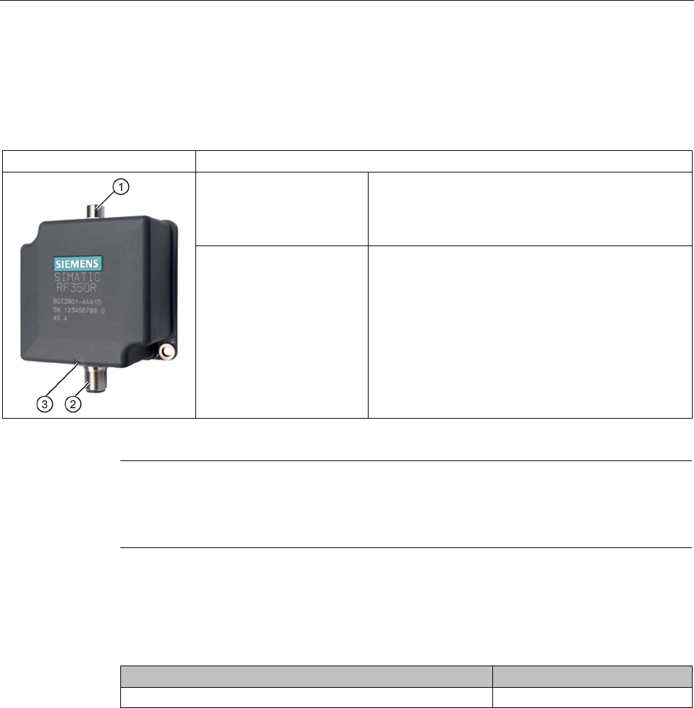
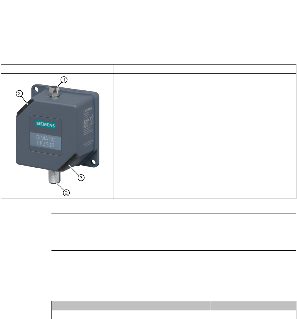
SIMATIC RF350R
Characteristics
Design ① Antenna connection
② RS-422 interface
③
Status display
Area of application Identification tasks in assembly lines in harsh industrial
environments; for external antennas
(ANT 1, ANT 3, ANT 12, ANT 18, ANT 30)
Note
Reader requires external antennas
Note that the RF350R reader is designed only for operation wit
h external antennas and only
works in conjunction with the antennas ANT 1, ANT 3, ANT 12, ANT 18 or ANT 30.
5.4.2.2
Ordering data for RF350R
Table 5- 14 Ordering data for RF350R
Article number
RF350R with RS-422 interface (3964R)
6GT2801-4AB10
Readers
5.4 SIMATIC RF340R/RF350R
SIMATIC RF300
158 System Manual, 07/2017, C79000-G8976-C345-07
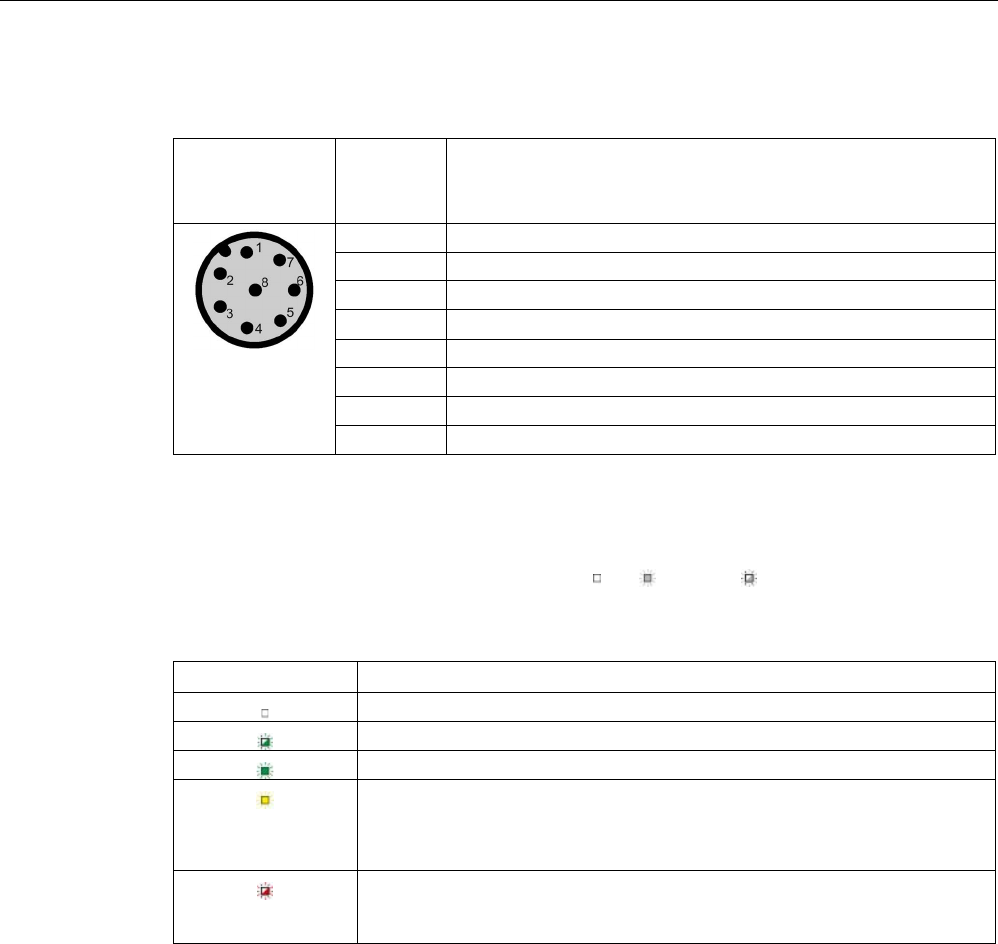
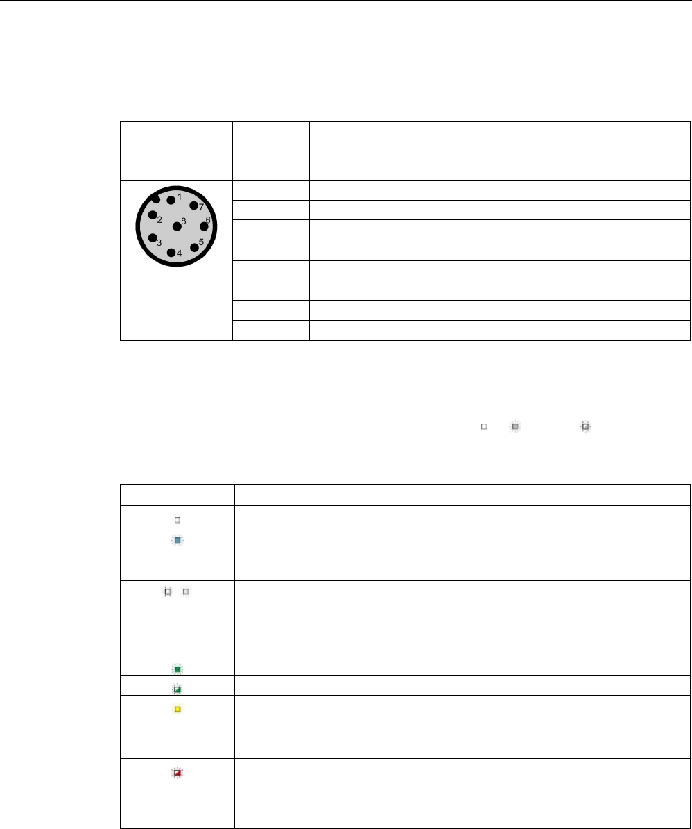
5.4.2.3
Pin assignment of RF350R RS422 interface
Pin
Pin
Device end
8-pin M12
Assignment
1
+ 24 V
2
- Transmit
3
0 V
4 + Transmit
5
+ Receive
6
- Receive
7
Unassigned
8
Earth (shield)
5.4.2.4
LED operating display
The operational statuses of the reader are displayed by the LEDs. The LED can adopt the
colors green, red or yellow and the statuses off , on , flashing :
Table 5- 15 LED operating display on the reader
LED
Meaning
The reader is turned off.
Operating voltage present, reader not initialized or antenna switched off
Operating voltage present, reader initialized and antenna switched on
• Operating mode "with presence": Transponder present
• Operating mode "without presence": Transponder present and command
currently being executed
There is an error. The number of flashes provides information about the cur-
rent error. You will find more information on error messages in the section
"System diagnostics (Page 413)".
5.4.2.5
Ensuring reliable data exchange
The "center point" of the transponder must be situated within the transmission window.
5.4.2.6
Metal-free area
The RF350R reader does not have an internal antenna. Operation is not affected by
mounting on metal or flush-mounting in metal. For information about the metal-free area
required by the external antennas, refer to the corresponding section of the chapter
AUTOHOTSPOT.

Readers
5.4 SIMATIC RF340R/RF350R
SIMATIC RF300
System Manual, 07/2017, C79000-G8976-C345-07 159
5.4.2.7
Technical specifications
Table 5- 16 Technical specifications of the RF350R reader
6GT2801-4AB10
Product type designation
SIMATIC RF350R
Radio frequencies
Operating frequency, rated value
13.56 MHz
Electrical data
Maximum range
• ANT 1 • 140 mm
• ANT 3 / ANT 3 S • 50 mm / 20 mm
• ANT 12 • 16 mm
• ANT 18 • 35 mm
• ANT 30 • 55 mm
Maximum data transmission speed
reader ↔ transponder
RF300 transponder ISO transponder
• Read • approx. 8000
bytes/s
• approx. 1500
bytes/s
• Write • approx. 8000
bytes/s
• approx. 1500
bytes/s
Transmission speed
19.2, 57.6, 115.2 kBd
Read/write distances of the reader See section "Field data for transponders, readers
and antennas (Page 51)."
MTBF (Mean Time Between Failures)
140 years
Interfaces
Electrical connector design
M12, 8-pin
Antenna connector design
M8, 4-pin
Standard for interfaces for communication
RS-422 (3964R protocol)
Antenna External, antennas ANT 1, ANT 3, ANT 12, ANT
18 or ANT 30
Mechanical specifications
Enclosure
• Material • Plastic PA 12
• Color • Anthracite
Recommended distance to metal
0 mm

Readers
5.4 SIMATIC RF340R/RF350R
SIMATIC RF300
160 System Manual, 07/2017, C79000-G8976-C345-07
6GT2801-4AB10
Supply voltage, current consumption, power loss
Supply voltage
24 VDC
Typical current consumption
100 mA
Permitted ambient conditions
Ambient temperature
• During operation • -25 to +70 ℃
• During transportation and storage • -40 to +85 ℃
Degree of protection to EN 60529
IP65
Shock-resistant to EN 60721-3-7, Class 7 M3
500 m/s
2
Vibration-resistant to EN 60721-3-7, Class 7 M3
200 m/s
2
Torsion and bending load
Not permitted
Design, dimensions and weights
Dimensions (L x W x H)
75 x 75 x 41 mm
Weight
250 g
Type of mounting 2 x M5 screws;
1.5 Nm
Cable length for RS-422 interface, maximum
1000 m
LED display design
3-color LED
Standards, specifications, approvals
Proof of suitability Radio to R&TTE directives EN 300330,
EN 301489, CE, FCC, UL/CSA,
Ex approval

Readers
5.4 SIMATIC RF340R/RF350R
SIMATIC RF300
System Manual, 07/2017, C79000-G8976-C345-07 161
5.4.2.8
Approvals
FCC information
Siemens SIMATIC RF350R (MLFB 6GT2801-4AA10); FCC ID NXW-RF350R
Siemens SIMATIC RF350R (MLFB 6GT2801-4AB10); FCC ID NXW-RF350R01
This device complies with part 15 of the FCC rules. Operation is subject to the following two
conditions:
(1) This device may not cause harmful interference, and
(2) this device must accept any interference received, including interference that may cause
undesired operation.
Caution
Any changes or modifications not expressly approved by the party responsible for
compliance could void the user's authority to operate the equipment.
Note
This equipment has been tested and found to comply with the limits for a Class A digital
device, pursuant to part 15 of the FCC Rules.
These limits are designed to provide reasonable protection against harmful interference
when the equipment is operated in a commercial environment. This equipment generates,
uses, and can radiate radio frequency energy and, if not installed and used in accordance
with the instruction manual, may cause harmful interference to radio communications.
Operation of this equipment in a residential area is likely to cause harmful interference in
which case the user will be required to correct the interference at his own expense.
IC information
This device complies with Industry Canada licence-exempt RSS standard(s). Operation is
subject to the following two conditions:
(1) This device may not cause interference, and
(2) this device must accept any interference, including interference that may cause
undesired operation of the device.
Le présent appareil est conforme aux CNR d`Industrie Canada applicables aux appareils
radio exempts de licence. L`exploitation est autorisée aux deux conditions suivantes :
(1) L`appareil ne doit pas produire de brouillage, et
(2) l'utilisateur de l`appareil doit accepter tout brouillage radioélectrique subi, même si le
brouillage est susceptible d`en compromettre le fonctionnement.
Readers
5.4 SIMATIC RF340R/RF350R
SIMATIC RF300
162 System Manual, 07/2017, C79000-G8976-C345-07
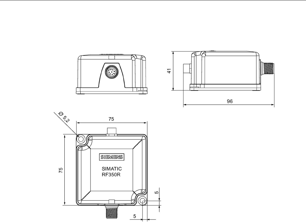
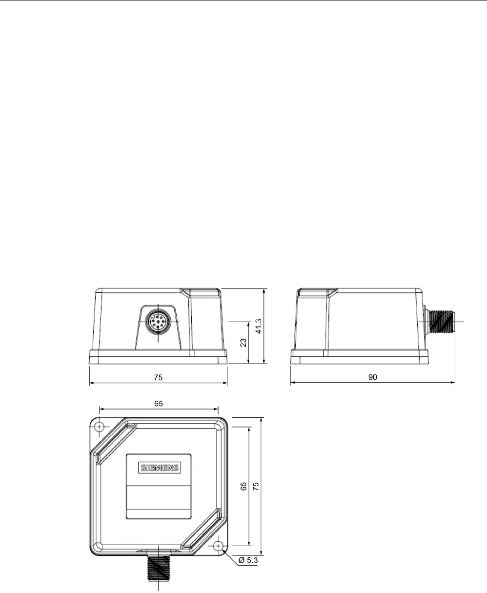
5.4.2.9
Dimension drawing
Figure 5-17 RF350R dimension drawing
Dimensions in mm
Readers
5.4 SIMATIC RF340R/RF350R
SIMATIC RF300
System Manual, 07/2017, C79000-G8976-C345-07 163
5.4.3
Use of the reader in hazardous areas
TÜV NORD CERT GmbH as accredited test center and certification body, no. 0044 as per
Article 9 of the Directive 94/9/EC of the European Council of 23 March 1994, has confirmed
the compliance with the essential health and safety requirements relating to the design and
construction of equipment and protective systems intended for use in hazardous areas as
per Annex II of the Directive. The essential health and safety requirements are satisfied in
accordance with the following standards:
Document
Title
EN 60079-0: 2006 Electrical equipment for hazardous gas atmospheres -
Part 0: General requirements
EN 60079-15: 2005 Electrical equipment for hazardous gas atmospheres -
Part 15: Design, testing and identification of electrical equipment with
type of protection "n"
IEC 61241 -0: 2006 Electrical apparatus for use in the presence of combustible dust -
Part 0: General requirements
IEC 61241 -1: 2004 Electrical apparatus for use in the presence of combustible dust -
Part 1: Protection through enclosure
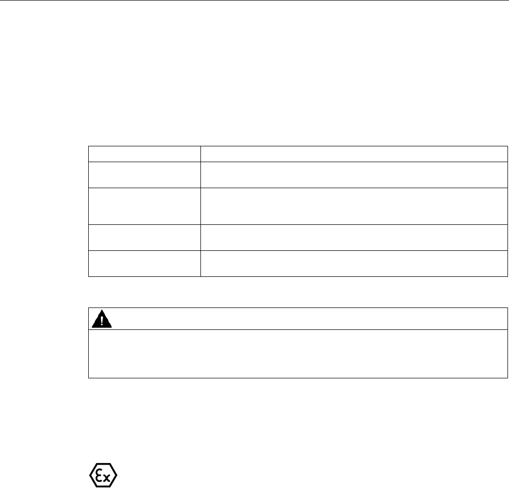
WARNING
EXPLOSION HAZARD
DO NOT CONNECT OR DISCONNECT EQUIPMENT WHEN A FLAMMABLE OR
COMBUSTIBLE ATMOSPHERE IS PRESENT.
Identification
The identification of the electrical equipment as an enclosed unit is:
II 3 G Ex nA nC IIB T5
II 3 D Ex tD A22 IP6x T80 °C
-25 °C to +70 °C
U
n
= 20 to 30 VDC
The equipment also has the following additional markings:
XXXYYYZZZ
[= serial number, is assigned during production]
TÜV 10 ATEX 556039
[= certificate number]
Readers
5.4 SIMATIC RF340R/RF350R
SIMATIC RF300
164 System Manual, 07/2017, C79000-G8976-C345-07
5.4.3.1
Use of the readers in hazardous areas for gases
Temperature class delineation for gases
The temperature class of the reader for hazardous areas depends on the ambient
temperature range:
Ambient temperature range
Temperature class
-25 °C to +70 °C
T5
WARNING
Ignitions of gas-air mixtures
When using the RF340R/RF350R readers, check to ensure that the temperature class is
observed in respect of the requirements of the area of application.
Non-compliance with the permitted temperature ranges while using the reader can lead to
ignitions of gas-air mixtures.
5.4.3.2
Use of the readers in hazardous areas for dusts
The equipment is suitable for dusts whose ignition temperatures for a dust layer of 5 mm are
higher than 80 °C (smoldering temperature). With the ignition temperature according to type
of protection iD specified here in compliance with IEC 61241-0 and IEC 61241-11, the
smoldering temperature of the dust layer is referenced in this case.
Temperature class delineation for dusts
Ambient temperature range
Temperature value
-25 °C < Ta < +70 °C
T80 °C
WARNING
Ignitions of dust-air mixtures
When using the RF340R/RF350R readers, check to ensure that the temperature values are
observed in respect of the requirements of the area of application.
Non-compliance with the permitted temperature ranges while using the reader can lead to
ignitions of dust-air mixtures.

Readers
5.4 SIMATIC RF340R/RF350R
SIMATIC RF300
System Manual, 07/2017, C79000-G8976-C345-07 165
5.4.3.3
Installation and operating conditions for the hazardous area
NOTICE
Device may be damaged
Note the following conditions when installing and operating the device in a hazardous zone
to avoid damage:
• Making and breaking of circuits is permitted only in a de-energized state.
• The maximum surface temperature, corresponding to the marking, applies only for
operation without a cover of dust.
• The device may only be operated in such a way that adequate protection against UV
light is ensured.
• The device may not be operated in areas influenced by processes that generate high
electrostatic charges.
• The equipment must be installed so that it is mechanically protected.
• The device sockets must be protected with a shrink-on tube.
• The 8 pin connector must be grounded via its supply line.
• The device may only be operated with accessories specified or supplied by the
manufacturer. All the points above also apply to the accessories (cables and
connectors) and to the antennas (exception: the housing of antenna 1 does not need to
be installed with impact protection).
Readers
5.5 SIMATIC RF340R/RF350R - 2nd generation
SIMATIC RF300
166 System Manual, 07/2017, C79000-G8976-C345-07
5.5
SIMATIC RF340R/RF350R - 2nd generation
5.5.1
SIMATIC RF340R - 2nd generation
5.5.1.1
Features
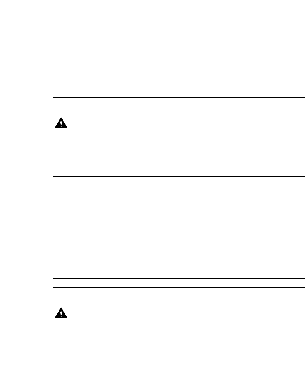
SIMATIC RF340R
Characteristics
Design ① RS-422 interface
②
LED operating display
Area of application Identification tasks on assembly lines in harsh
industrial environments
5.5.1.2
Ordering data
Table 5- 17 Ordering data for RF340R
Article number
RF340R with RS-422 interface (3964R)
6GT2801-2BA10

Readers
5.5 SIMATIC RF340R/RF350R - 2nd generation
SIMATIC RF300
System Manual, 07/2017, C79000-G8976-C345-07 167
5.5.1.3
Pin assignment of the RS-422 interface
Table 5- 18 Pin assignment
Pin
Pin
Device end
8-pin M12
Assignment
1
+ 24 V
2
- Transmit
3
0 V
4 + Transmit
5
+ Receive
6
- Receive
7
Unassigned
8
Earth (shield)
5.5.1.4
LED operating display
The operational statuses of the reader are displayed by two LEDs. The LEDs can adopt the
colors white green, red, yellow or blue and the statuses off , on , flashing :
Table 5- 19 Display elements
LED
Meaning
The reader is turned off.
The reader is turned on and is searching for transponders.
The reader is in the "Setup" mode, in the "Search for transponders" status and
has not yet received a "RESET" command and is not ready.
/ There is transponder in the antenna field.
The reader is in the "Setup" mode, in the status "Show quality", has not yet re-
ceived a "RESET" command and is not ready.
Depending on the signal strength, the LED flickers or is lit permanently.
The reader has received a "RESET" command.
The reader is turned on, the antenna is turned off.
• Operating mode "with presence": Transponder present
• Operating mode "without presence": Transponder present and command
currently being executed
There is an error. The number of flashes provides information about the current
error.
You will find more information on error messages in the section "System diag-
nostics (Page 413)".
5.5.1.5
Ensuring reliable data exchange
The "center point" of the transponder must be situated within the transmission window.
Readers
5.5 SIMATIC RF340R/RF350R - 2nd generation
SIMATIC RF300
168 System Manual, 07/2017, C79000-G8976-C345-07
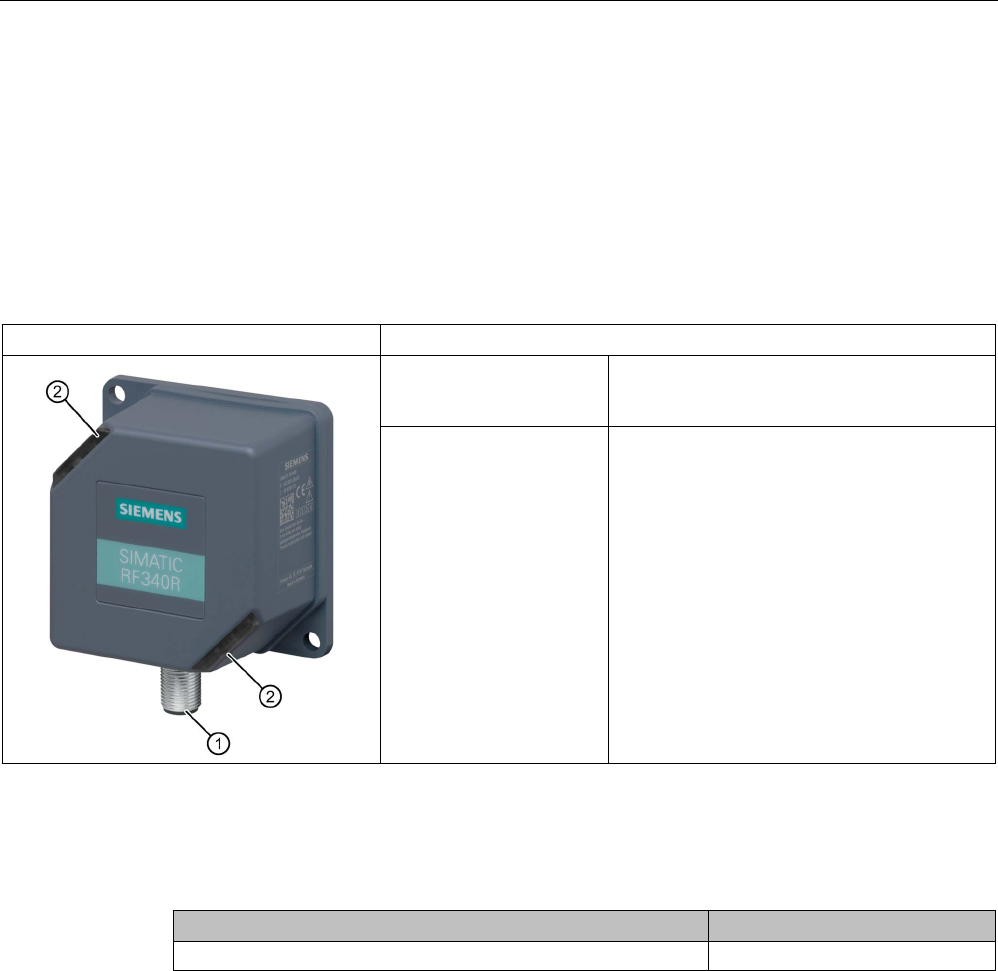
5.5.1.6
Metal-free area
The RF340R can be flush-mounted in metal. Allow for a possible reduction in the field data.
To avoid any influence on the field data, the distance "a" should be kept to.
a ≥
20 mm
Figure 5-18 Metal-free area for RF340R
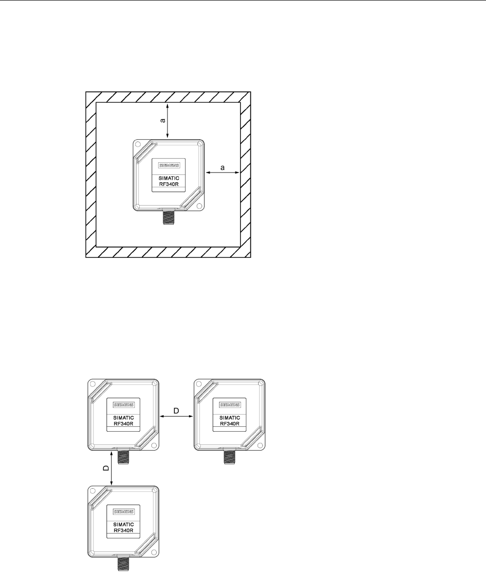
5.5.1.7
Minimum distance between RF340R readers
RF340R side by side
D ≥
350 mm (with 2 readers)
D ≥
500 mm (with more than 2 readers)
Figure 5-19 Minimum distance between RF340R readers
Readers
5.5 SIMATIC RF340R/RF350R - 2nd generation
SIMATIC RF300
System Manual, 07/2017, C79000-G8976-C345-07 169
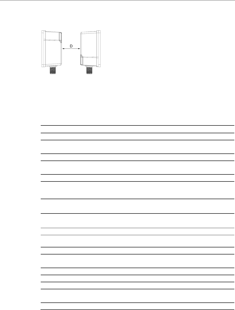
RF340R face-of-face
D ≥
500 mm
Figure 5-20 Face-of-face distance between two RF340Rs
5.5.1.8
Technical specifications
Table 5- 20 Technical specifications of the RF340R reader
6GT2801-2BA10
Product type designation
SIMATIC RF340R
Radio frequencies
Operating frequency, rated value
13.56 MHz
Electrical data
Maximum range
140 mm
Maximum data transmission speed
reader ↔ transponder
RF300
transponder
ISO
transponder
(MDS D)
ISO tran-
sponder
(MDS E)
• Read • ≤ 8000
bytes/s
• ≤ 3300
bytes/s
• ≤ 3400
bytes/s
• Write • ≤ 8000
bytes/s
• ≤ 1700
bytes/s
• ≤ 800
bytes/s
Transmission speed
19.2, 57.6, 115.2 kBd
Read/write distances of the reader See section "Field data for transponders, readers
and antennas (Page 51)."
MTBF (Mean Time Between Failures)
260 years
Interfaces
Electrical connector design
M12, 8-pin
Standard for interfaces for communication
RS-422 (3964R protocol)
Antenna
integrated
Mechanical specifications
Enclosure

Readers
5.5 SIMATIC RF340R/RF350R - 2nd generation
SIMATIC RF300
170 System Manual, 07/2017, C79000-G8976-C345-07
6GT2801-2BA10
• Material • Plastic PA 12
• Color • TI-Grey
Recommended distance to metal
0 mm
Supply voltage, current consumption, power loss
Supply voltage
24 VDC
Typical current consumption
60 mA
Permitted ambient conditions
Ambient temperature
• During operation • -25 to +70 ℃
• During transportation and storage • -40 to +85 ℃
Degree of protection to EN 60529
IP67
Shock-resistant to EN 60721-3-7, Class 7 M3
500 m/s
2
Vibration-resistant to EN 60721-3-7, Class 7 M3
200 m/s
2
Torsion and bending load
Not permitted
Design, dimensions and weights
Dimensions (L x W x H)
75 x 75 x 41 mm
Weight
210 g
Type of mounting 2 x M5 screws;
1.5 Nm
Cable length for RS-422 interface, maximum
1000 m
LED display design 2 LEDs,
5 colors
Standards, specifications, approvals
Proof of suitability Radio to R&TTE directives EN 300330,
EN 301489, CE, FCC, UL/CSA (IEC 61010),
Ex approval

Readers
5.5 SIMATIC RF340R/RF350R - 2nd generation
SIMATIC RF300
System Manual, 07/2017, C79000-G8976-C345-07 171
5.5.1.9
Approvals
FCC information
Siemens SIMATIC RF340R (MLFB 6GT2801-2BA10); FCC ID NXW-RF340R02
This device complies with part 15 of the FCC rules. Operation is subject to the following two
conditions:
(1) This device may not cause harmful interference, and
(2) this device must accept any interference received, including interference that may cause
undesired operation.
Caution
Any changes or modifications not expressly approved by the party responsible for
compliance could void the user's authority to operate the equipment.
Note
This equipment has been tested and found to comply with the limits for a Class A digital
device, pursuant to part 15 of the FCC Rules.
These limits are designed to provide reasonable protection against harmful interference
when the equipment is operated in a commercial environment. This equipment generates,
uses, and can radiate radio frequency energy and, if not installed and used in accordance
with the instruction manual, may cause harmful interference to radio communications.
Operation of this equipment in a residential area is likely to cause harmful interference in
which case the user will be required to correct the interference at his own expense.
IC information
This device complies with Industry Canada licence-exempt RSS standard(s). Operation is
subject to the following two conditions:
(1) This device may not cause interference, and
(2) this device must accept any interference, including interference that may cause
undesired operation of the device.
Le présent appareil est conforme aux CNR d`Industrie Canada applicables aux appareils
radio exempts de licence. L`exploitation est autorisée aux deux conditions suivantes :
(1) L`appareil ne doit pas produire de brouillage, et
(2) l'utilisateur de l`appareil doit accepter tout brouillage radioélectrique subi, même si le
brouillage est susceptible d`en compromettre le fonctionnement.
Readers
5.5 SIMATIC RF340R/RF350R - 2nd generation
SIMATIC RF300
172 System Manual, 07/2017, C79000-G8976-C345-07
UL information (IEC 61010-1 / IEC 61010-2-201)
This standard applies to equipment designed to be safe at least under the following
conditions:
● a) indoor use;
● b) altitude up to 2 000 m;
● c) temperature -25 °C to 70 °C;
● d) maximum relative humidity 80 % for temperature up to 31 °C decreasing linearly to 50
% relative humidity at 40 °C;
● e) TRANSIENT OVERVALTAGES up to the levels of OVERVALTAGE CATEGORY II,
NOTE 1: These levels of transient overvoltage are typical for equipment supplied from the
building wiring.
● f) using a "NEC Class 2" power supply is required
● g) the device is categorized as pollution degree 3/4
5.5.1.10
Dimension drawing
Figure 5-21 Dimension drawing for RF340R
Dimensions in mm
Readers
5.5 SIMATIC RF340R/RF350R - 2nd generation
SIMATIC RF300
System Manual, 07/2017, C79000-G8976-C345-07 173
5.5.2
SIMATIC RF350R - 2nd generation
5.5.2.1
Features
SIMATIC RF350R
Characteristics
Design ① Antenna connection
② RS-422 interface
③
LED operating display
Area of application Identification tasks in assembly lines in harsh
industrial environments; for external antennas
(ANT 1, ANT 3, ANT 12, ANT 18, ANT 30)
Note
Reader requires external antennas
Note that the RF350R reader is designed only for operation with external antennas and only
works in conjunction with the antennas ANT 1, ANT 3, ANT 12, ANT 18 or ANT 30.
5.5.2.2
Ordering data
Table 5- 21 Ordering data for RF350R
Article number
RF350R with RS-422 interface (3964R)
6GT2801-4BA10
Readers
5.5 SIMATIC RF340R/RF350R - 2nd generation
SIMATIC RF300
174 System Manual, 07/2017, C79000-G8976-C345-07
5.5.2.3
Pin assignment of the RS-422 interface
Table 5- 22 Pin assignment
Pin
Pin
Device end
8-pin M12
Assignment
1
+ 24 V
2
- Transmit
3
0 V
4 + Transmit
5
+ Receive
6
- Receive
7
Unassigned
8
Earth (shield)
5.5.2.4
LED operating display
The operational statuses of the reader are displayed by two LEDs. The LEDs can adopt the
colors white green, red, yellow or blue and the statuses off , on , flashing :
Table 5- 23 Display elements
LED
Meaning
The reader is turned off.
The reader is turned on and is searching for transponders.
The reader is in the "Setup" mode, in the "Search for transponders" status and
has not yet received a "RESET" command and is not ready.
/ There is transponder in the antenna field.
The reader is in the "Setup" mode, in the status "Show quality", has not yet re-
ceived a "RESET" command and is not ready.
Depending on the signal strength, the LED flickers or is lit permanently.
The reader has received a "RESET" command.
The reader is turned on, the antenna is turned off.
• Operating mode "with presence": Transponder present
• Operating mode "without presence": Transponder present and command
currently being executed
There is an error. The number of flashes provides information about the current
error.
You will find more information on error messages in the section "System diag-
nostics (Page 413)".
5.5.2.5
Ensuring reliable data exchange
The "center point" of the transponder must be situated within the transmission window.

Readers
5.5 SIMATIC RF340R/RF350R - 2nd generation
SIMATIC RF300
System Manual, 07/2017, C79000-G8976-C345-07 175
5.5.2.6
Metal-free area
The RF350R reader does not have an internal antenna. Operation is not affected by
mounting on metal or flush-mounting in metal. For information about the metal-free area
required by the external antennas, refer to the corresponding section of the chapter
"Antennas (Page 221)".
5.5.2.7
Technical specifications
Table 5- 24 Technical specifications of the RF350R reader
6GT2801-4BA10
Product type designation
SIMATIC RF350R
Radio frequencies
Operating frequency, rated value
13.56 MHz
Electrical data
Maximum range
• ANT 1 • 140 mm
• ANT 3 • 50 mm
• ANT 12 • 16 mm
• ANT 18 • 35 mm
• ANT 30 • 55 mm
Maximum data transmission speed
reader ↔ transponder
RF300
transponder
ISO
transponder
(MDS D)
ISO tran-
sponder
(MDS E)
• Read • ≤ 8000
bytes/s
• ≤ 3300
bytes/s
• ≤ 3400
bytes/s
• Write • ≤ 8000
bytes/s
• ≤ 1700
bytes/s
• ≤ 800
bytes/s
Transmission speed
19.2, 57.6, 115.2 kBd
Read/write distances of the reader See section "Field data for transponders, readers
and antennas (Page 51)."
MTBF (Mean Time Between Failures)
260 years
Interfaces
Electrical connector design
M12, 8-pin
Antenna connector design
M8, 4-pin
Standard for interfaces for communication
RS-422 (3964R protocol)
Antenna External, antennas ANT 1, ANT 3, ANT 12, ANT
18 or ANT 30

Readers
5.5 SIMATIC RF340R/RF350R - 2nd generation
SIMATIC RF300
176 System Manual, 07/2017, C79000-G8976-C345-07
6GT2801-4BA10
Mechanical specifications
Enclosure
• Material • Plastic PA 12
• Color • TI-Grey
Recommended distance to metal
0 mm
Supply voltage, current consumption, power loss
Supply voltage
24 VDC
Typical current consumption
60 mA
Permitted ambient conditions
Ambient temperature
• During operation • -25 to +70 ℃
• During transportation and storage • -40 to +85 ℃
Degree of protection to EN 60529
IP65
Shock-resistant to EN 60721-3-7, Class 7 M3
500 m/s
2
Vibration-resistant to EN 60721-3-7, Class 7 M3
200 m/s
2
Torsion and bending load
Not permitted
Design, dimensions and weights
Dimensions (L x W x H)
75 x 75 x 41 mm
Weight
250 g
Type of mounting 2 x M5 screws;
1.5 Nm
Cable length for RS-422 interface, maximum
1000 m
LED display design 2 LEDs,
5 colors
Standards, specifications, approvals
Proof of suitability Radio to R&TTE directives EN 300330,
EN 301489, CE, FCC, UL/CSA (IEC 61010),
Ex approval

Readers
5.5 SIMATIC RF340R/RF350R - 2nd generation
SIMATIC RF300
System Manual, 07/2017, C79000-G8976-C345-07 177
5.5.2.8
Approvals
FCC information
Siemens SIMATIC RF350R (MLFB 6GT2801-4BA10); FCC ID NXW-RF350R02
This device complies with part 15 of the FCC rules. Operation is subject to the following two
conditions:
(1) This device may not cause harmful interference, and
(2) this device must accept any interference received, including interference that may cause
undesired operation.
Caution
Any changes or modifications not expressly approved by the party responsible for
compliance could void the user's authority to operate the equipment.
Note
This equipment has been tested and found to comply with the limits for a Class A digital
device, pursuant to part 15 of the FCC Rules.
These limits are designed to provide reasonable protection against harmful interference
when the equipment is operated in a commercial environment. This equipment generates,
uses, and can radiate radio frequency energy and, if not installed and used in accordance
with the instruction manual, may cause harmful interference to radio communications.
Operation of this equipment in a residential area is likely to cause harmful interference in
which case the user will be required to correct the interference at his own expense.
IC information
This device complies with Industry Canada licence-exempt RSS standard(s). Operation is
subject to the following two conditions:
(1) This device may not cause interference, and
(2) this device must accept any interference, including interference that may cause
undesired operation of the device.
Le présent appareil est conforme aux CNR d`Industrie Canada applicables aux appareils
radio exempts de licence. L`exploitation est autorisée aux deux conditions suivantes :
(1) L`appareil ne doit pas produire de brouillage, et
(2) l'utilisateur de l`appareil doit accepter tout brouillage radioélectrique subi, même si le
brouillage est susceptible d`en compromettre le fonctionnement.
Readers
5.5 SIMATIC RF340R/RF350R - 2nd generation
SIMATIC RF300
178 System Manual, 07/2017, C79000-G8976-C345-07
UL information (IEC 61010-1 / IEC 61010-2-201)
This standard applies to equipment designed to be safe at least under the following
conditions:
● a) indoor use;
● b) altitude up to 2 000 m;
● c) temperature -25 °C to 70 °C;
● d) maximum relative humidity 80 % for temperature up to 31 °C decreasing linearly to 50
% relative humidity at 40 °C;
● e) TRANSIENT OVERVALTAGES up to the levels of OVERVALTAGE CATEGORY II,
NOTE 1: These levels of transient overvoltage are typical for equipment supplied from the
building wiring.
● f) using a "NEC Class 2" power supply is required
● g) the device is categorized as pollution degree 3/4
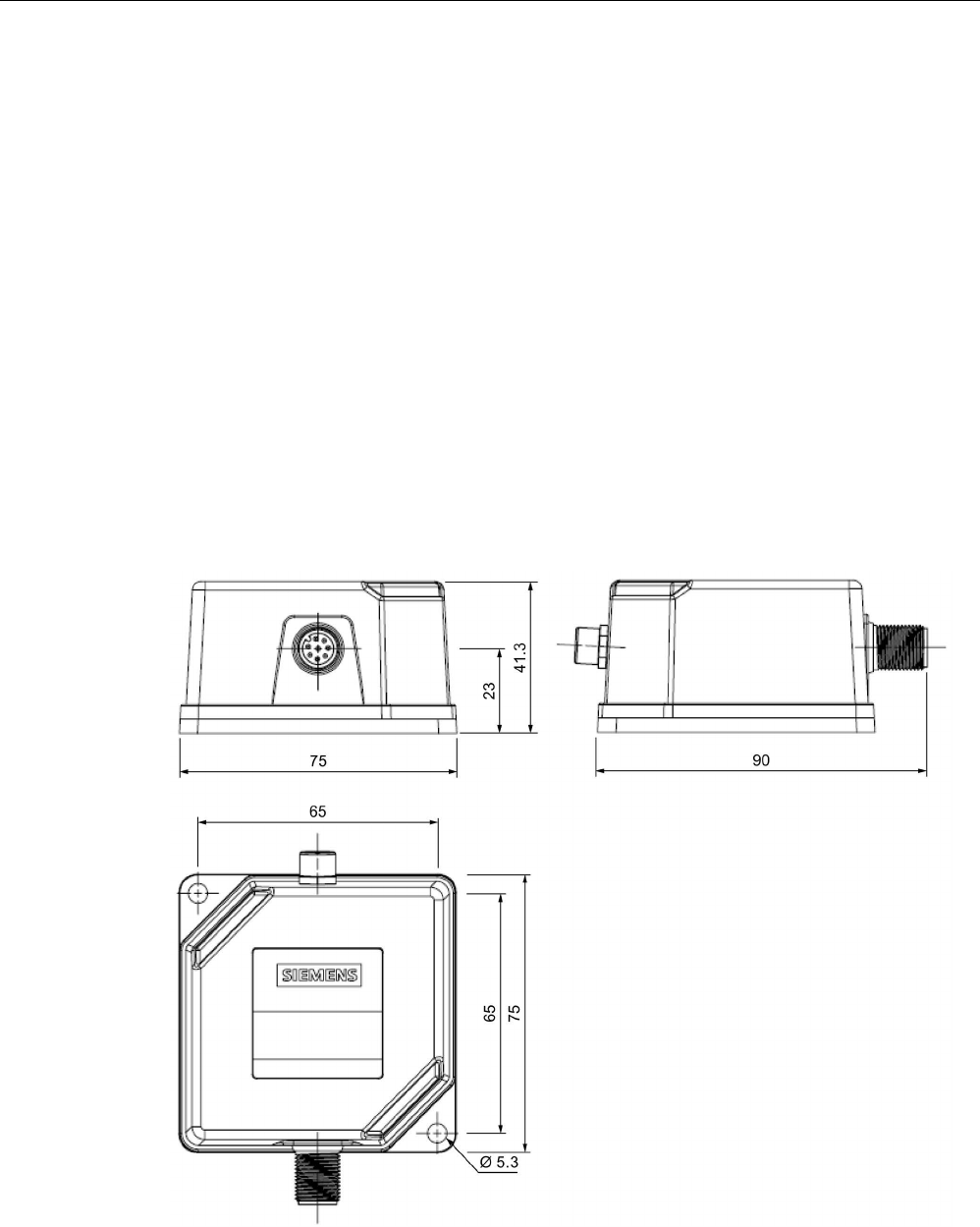
5.5.2.9
Dimension drawing
Figure 5-22 RF350R dimension drawing
Dimensions in mm
Readers
5.5 SIMATIC RF340R/RF350R - 2nd generation
SIMATIC RF300
System Manual, 07/2017, C79000-G8976-C345-07 179
5.5.3
Using the readers in a hazardous area
WARNING
Explosion hazard
In a flammable or combustible environment, no cables may be connected to or
disconnected from the device.
ATEX
The SIMATIC Ident products meet the requirements of explosion protection acc. to ATEX.
The products meet the requirements of the standards:
Document
Title
EN 60079-0 Hazardous areas
Part 0: Equipment - General requirements
EN 60079-7 Hazardous areas
Part 7: Equipment protection by increased safety "e"
EN 60079-31 Potentially explosive atmosphere
Part 31: Equipment dust ignition protection by enclosure "t"
You will find the current versions of the standards in the currently valid ATEX certificates.
ATEX mark
NOTICE
Validity only when the devices are marked
There is a corresponding approval only with devices to which the Ex mark is applied.
The identification of the electrical equipment as an enclosed unit is:
II 3 G Ex ec IIB T4 Gc
II 3 D Ex tc IIIC T80°C Dc
-25 °C ... +70 °C
Un = 24 VDC
The equipment also has the following additional information:
XXXYYYZZZ
[= serial number, is assigned during production]
DEMKO 17 ATEX 1767 X
[= certificate number]

Readers
5.5 SIMATIC RF340R/RF350R - 2nd generation
SIMATIC RF300
180 System Manual, 07/2017, C79000-G8976-C345-07
IECEx
The SIMATIC Ident products meet the requirements of explosion protection acc. to IECEx.
The products meet the requirements of the standards:
Document
Title
IEC 60079-0 Hazardous areas
Part 0: Equipment - General requirements
IEC 60079-7 Hazardous areas
Part 7: Equipment protection by increased safety "e"
IEC 60079-31 Potentially explosive atmosphere
Part 31: Equipment dust ignition protection by enclosure "t"
You will find the current versions of the standards in the currently valid IECEx certificates.
IECEx mark
NOTICE
Validity only when the devices are marked
There is a corresponding approval only with devices to which the IECEx mark is applied.
The identification of the electrical equipment as an enclosed unit is:
II 3 G Ex ec IIB T4 Gc
II 3 D Ex tc IIIC T80°C Dc
-25 °C ... +70 °C
U
n= 24 VDC
The equipment also has the following additional information:
XXXYYYZZZ
[= serial number, is assigned during production]
IECEx ULD 17.0031 X
[= certificate number]
Readers
5.5 SIMATIC RF340R/RF350R - 2nd generation
SIMATIC RF300
System Manual, 07/2017, C79000-G8976-C345-07 181
UL HAZ. LOC.
The SIMATIC Ident products meet the requirements of explosion protection acc. to UL HAZ.
LOC. The products meet the requirements of the standards:
Document
Title
UL 60079-0
Hazardous areas
Part 0: Equipment - General requirements
CSA C22.2 NO. 60079-0
UL 60079-7
Hazardous areas
Part 7: Equipment protection by increased safety "e"
CSA C22.2 NO. 60079-7
UL 60079-31
Potentially explosive atmosphere
Part 31: Equipment dust ignition protection by enclosure "t"
CSA C22.2 NO. 60079-31
You will find the current versions of the standards in the currently valid UL HAZ. LOC.
certificates
UL HAZ. LOC. mark
NOTICE
Validity only when the devices are marked
There is a corresponding approval only with devices to which the UL HAZ. LOC. mark is
applied.
The identification of the electrical equipment as an enclosed unit is:
E223122
IND.CONT.EQ FOR HAZ.LOC.
C
L.I, DIV.2, GP.C,D T4
CL.II, DIV.2, GP.F,G T80°C
AEx ec IIB T4, Ex ec IIB T4
AEx tc IIIC T80°C, Ex tc IIIC T80°C
-25 °C ... +70 °C
U
n
= 24 VDC
The equipment also has the following additional information:
XXXYYYZZZ
[= serial number, is assigned during production]
Readers
5.5 SIMATIC RF340R/RF350R - 2nd generation
SIMATIC RF300
182 System Manual, 07/2017, C79000-G8976-C345-07
5.5.3.1
Using the reader in hazardous area for gases
The temperature class of the reader for hazardous areas depends on the ambient
temperature range:
Ambient temperature range
Temperature class
-25 ℃ ... +70 ℃
T4
WARNING
Ignitions of gas-air mixtures
When using the reader, check to make sure that the temperature class is adhered to in
keeping with the requirements of the area of application
Non-compliance with the permitted temperature ranges while using the reader can lead to
ignitions of gas-air mixtures.
5.5.3.2
Using the reader in hazardous area for dust
The equipment is suitable for dusts whose ignition temperatures for a dust layer of 5 mm are
higher than 80 °C (smoldering temperature).
Ambient temperature range
Temperature value
-25 °C < Ta < +70 °C
T80 °C
WARNING
Ignitions of dust-air mixtures
When using the reader, check to make sure that the temperature values are adhered to in
keeping with the requirements of the area of application. Non-compliance with the pe
rmitted
temperature range while using the reader can lead to ignitions of dust-air mixtures.

Readers
5.5 SIMATIC RF340R/RF350R - 2nd generation
SIMATIC RF300
System Manual, 07/2017, C79000-G8976-C345-07 183
5.5.3.3
Installation and operating conditions for hazardous areas:
NOTICE
Risk of explosion
Risk of explosion of dust-air mixtures or gas-air mixtures and the device can be damaged.
Note the following conditions when installing and operating the device in a hazardous area:
• Making and breaking of circuits is permitted only in a de-energized state.
• The maximum surface temperature, corresponding to the marking, applies only for
operation without a cover of dust.
• The device may only be operated in such a way that adequate protection against UV
light is ensured.
• The device may not be operated in areas influenced by processes that generate high
electrostatic charges.
• The device must be installed so that it is mechanically protected.
• The grounding of the plug (8-pin) on the reader must be via its supply cable.
• The device may only be operated with accessories specified or supplied by the
manufacturer. All the points above also apply to the accessories (cables and
connectors) and to the antennas (exception: the housing of ANT 1 does not need to be
installed with impact protection).
• The device sockets incl. the metal parts of the connecting cable must have a shrink-on
sleeve pulled over them, in other words, all metal parts apart from the securing sockets
of the housing must be fully covered and be inaccessible.
• After disconnecting the connections (antenna cable, signal/supply cable), before the
plugs are inserted again, they must be checked for contamination and if necessary
cleaned.
Readers
5.6 SIMATIC RF380R
SIMATIC RF300
184 System Manual, 07/2017, C79000-G8976-C345-07
5.6
SIMATIC RF380R
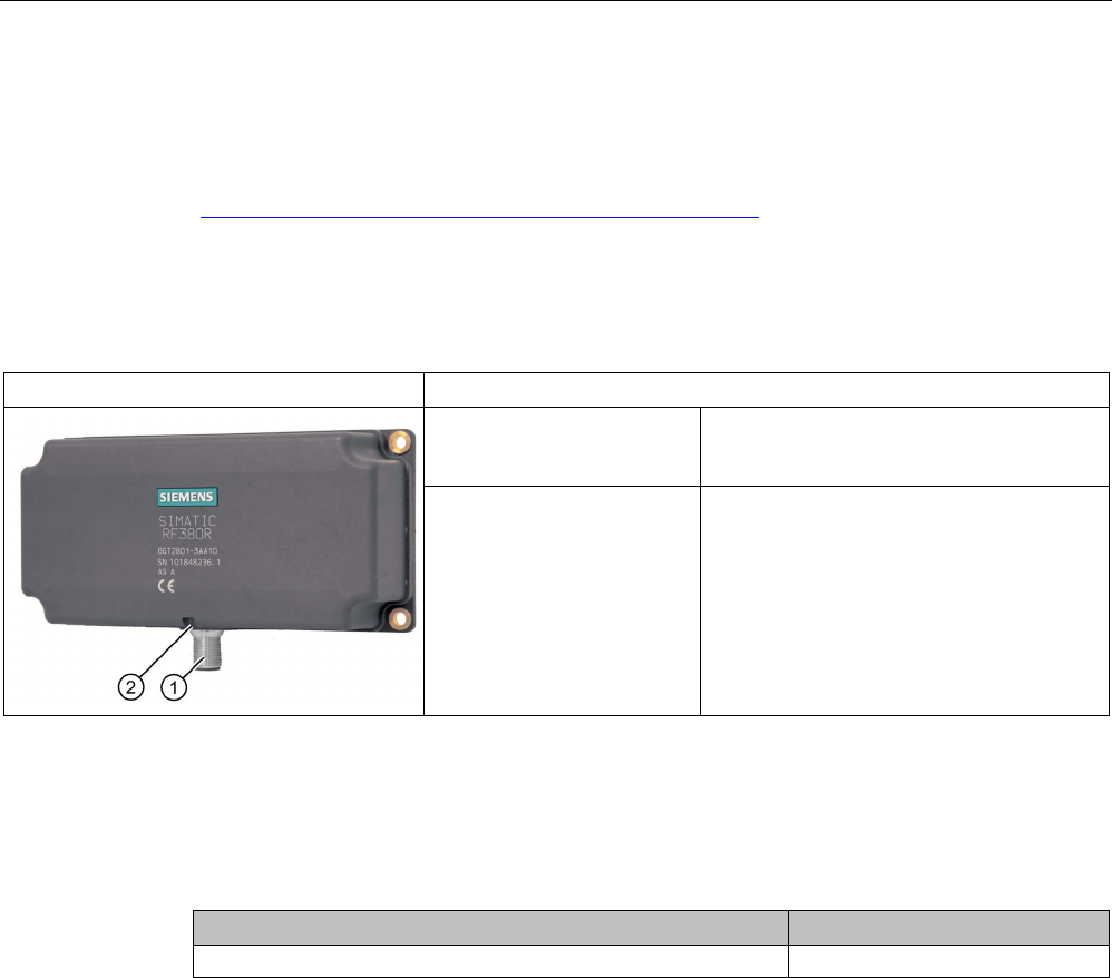
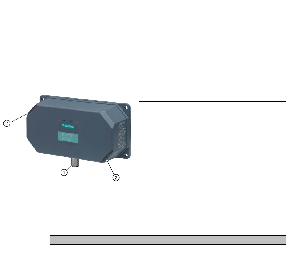
5.6.1
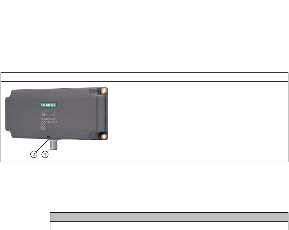
Features
SIMATIC RF380R
Characteristics
Design ① RS-232 or RS-422 interface
②
Status display
Area of application Identification tasks on assembly lines in
harsh industrial environments
5.6.2
RF380R ordering data
Table 5- 25 RF380R ordering data
Article number
RF380R with RS-232/RS-422 interface (3964R)
6GT2801-3AB10
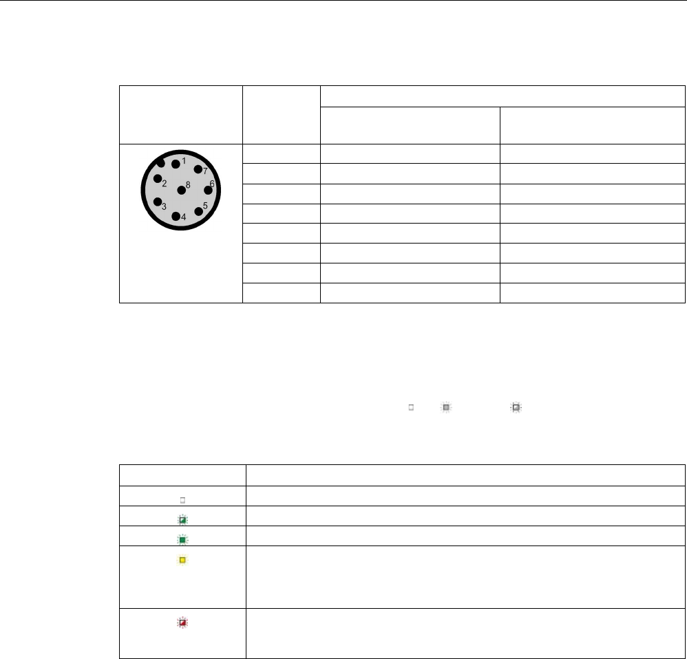
5.6.3
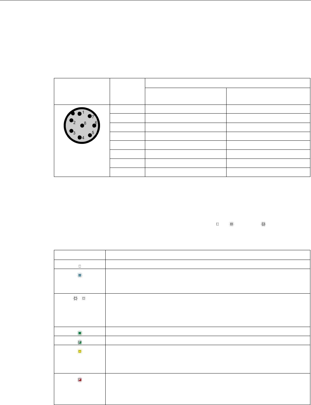
Pin assignment of RF380R RS-232/RS-422 interface
You can connect the RF380R reader to a higher-level system via the internal RS-422
interface or via the RS-232 interface. After connection, the interface module automatically
detects which interface has been used.
Readers
5.6 SIMATIC RF380R
SIMATIC RF300
System Manual, 07/2017, C79000-G8976-C345-07 185
Note correct assignment of the pins here:
Pin
Pin
Device end
8-pin M12
Assignment
RS-232
RS-422
1
+ 24 V
+ 24 V
2 RXD - Transmit
3
0 V
0 V
4
TXD
+ Transmit
5
not used
+ Receive
6
not used
- Receive
7
not used
not used
8
Ground (shield)
Ground (shield)
5.6.4
LED operating display
The operational statuses of the reader are displayed by the LEDs. The LED can adopt the
colors green, red or yellow and the statuses off , on , flashing :
Table 5- 26 LED operating display on the reader
LED
Meaning
The reader is turned off.
Operating voltage present, reader not initialized or antenna switched off
Operating voltage present, reader initialized and antenna switched on
• Operating mode "with presence": Transponder present
• Operating mode "without presence": Transponder present and command
currently being executed
There is an error. The number of flashes provides information about the cur-
rent error. You will find more information on error messages in the section
"System diagnostics (Page 413)".
5.6.5
Ensuring reliable data exchange
The "center point" of the transponder must be situated within the transmission window.

Readers
5.6 SIMATIC RF380R
SIMATIC RF300
186 System Manual, 07/2017, C79000-G8976-C345-07
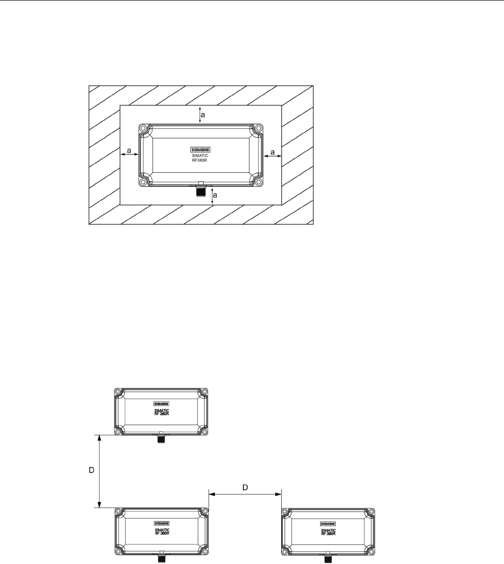
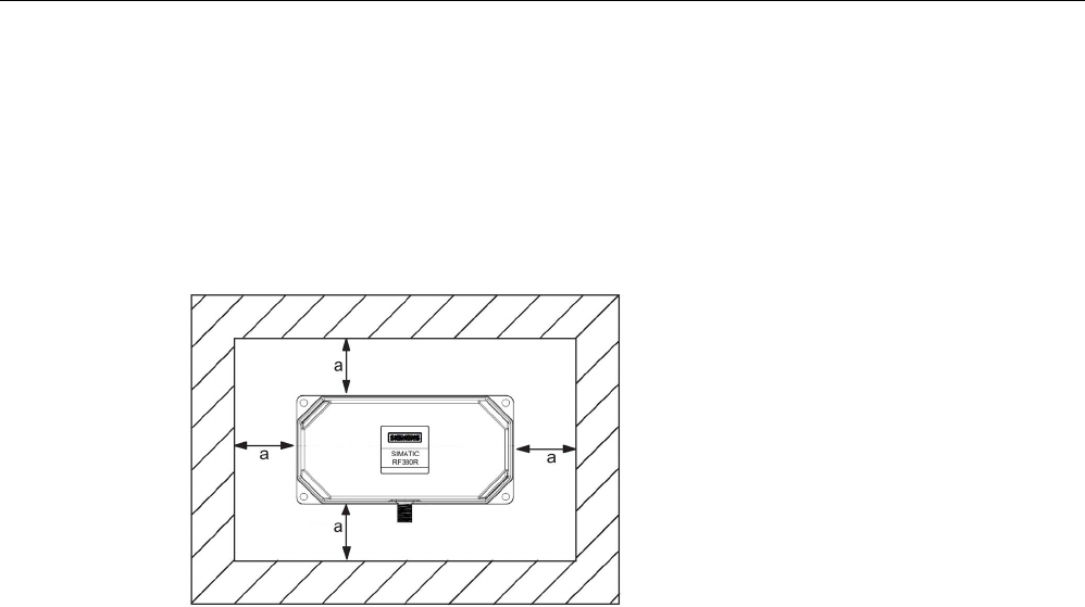
5.6.6
Metal-free area
The RF380R can be flush-mounted in metal. Allow for a possible reduction in the field data.
Figure 5-23 Metal-free area for RF380R
To avoid any impact on the field data, the distance a should be ≥ 20 mm.
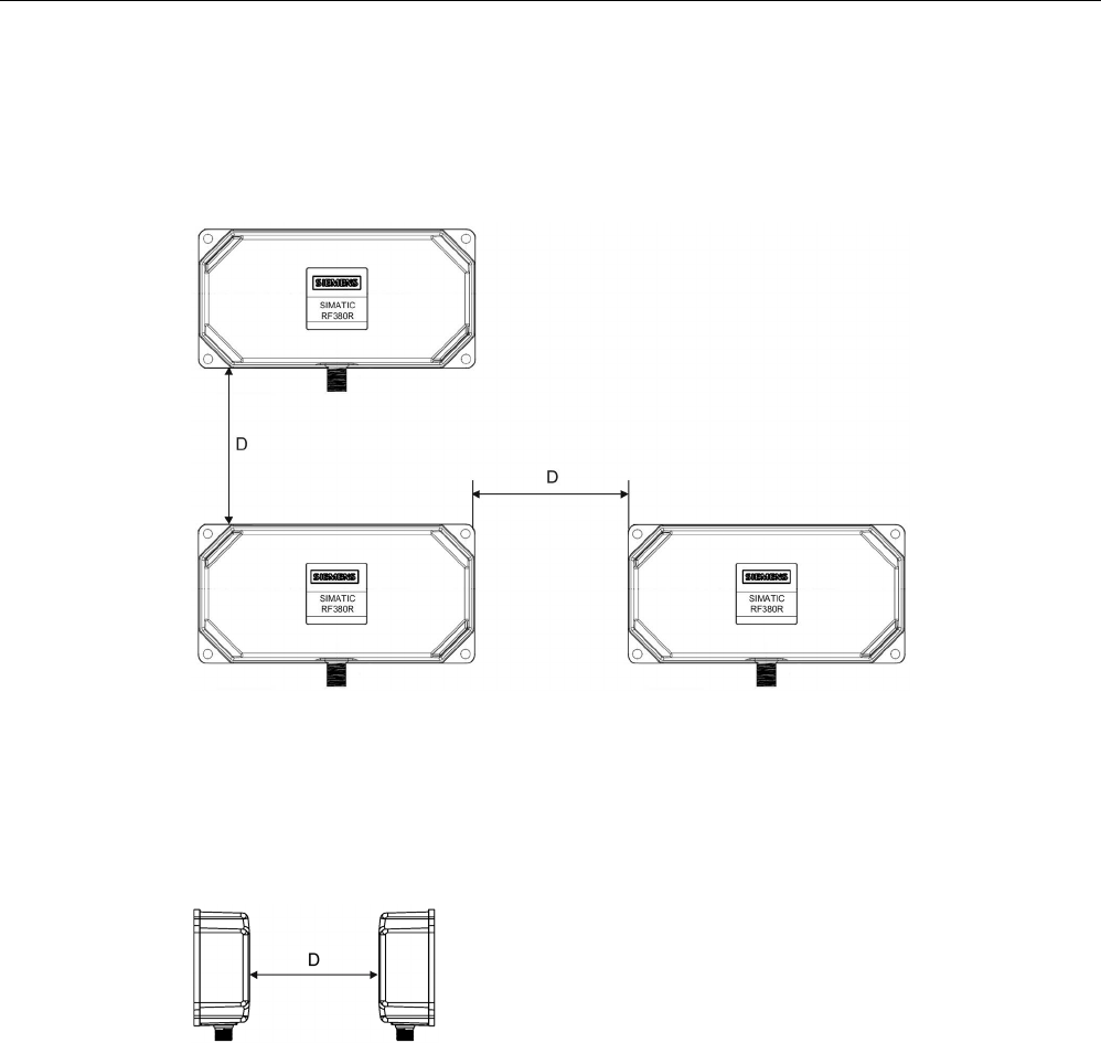
5.6.7
Minimum distance between RF380R readers
RF380R side by side
D
≥ 400 mm (with 2 readers)
D
≥ 500 mm (with more than 2 readers)
Figure 5-24 Minimum distance between RF380R readers

Readers
5.6 SIMATIC RF380R
SIMATIC RF300
System Manual, 07/2017, C79000-G8976-C345-07 187
RF380R face-to-face
D
≥ 800 mm
Figure 5-25 Face-to-face distance between two RF380R
5.6.8
Technical specifications
Table 5- 27 Technical specifications of the RF380R reader
6GT2801-3AB10
Product type designation
SIMATIC RF380R
Radio frequencies
Operating frequency, rated value
13.56 MHz
Electrical data
Maximum range
200 mm
Maximum data transmission speed
reader ↔ transponder
RF300 transponder ISO transponder
• Read • approx. 8000
bytes/s
• approx. 1500
bytes/s
• Write • approx. 8000
bytes/s
• approx. 1500
bytes/s
Transmission speed
19.2, 57.6, 115.2 kBd
Read/write distances of the reader See section "Field data for transponders, readers
and antennas (Page 51)."
MTBF (Mean Time Between Failures)
109 years
Interfaces
Electrical connector design
M12, 8-pin
Standard for interfaces for communication
RS-232/RS-422 (3964R protocol)
Antenna
integrated
Mechanical specifications
Enclosure
• Material • Plastic PA 12
• Color • Anthracite

Readers
5.6 SIMATIC RF380R
SIMATIC RF300
188 System Manual, 07/2017, C79000-G8976-C345-07
6GT2801-3AB10
Recommended distance to metal
0 mm
Supply voltage, current consumption, power loss
Supply voltage
24 VDC
Typical current consumption
160 mA
Permitted ambient conditions
Ambient temperature
• During operation • -25 to +70 ℃
• During transportation and storage • -40 to +85 ℃
Degree of protection to EN 60529
IP67
Shock-resistant to EN 60721-3-7, Class 7 M3
500 m/s
2
Vibration-resistant to EN 60721-3-7, Class 7 M3
200 m/s
2
Torsion and bending load
Not permitted
Design, dimensions and weights
Dimensions (L x W x H)
160 x 80 x 41 mm
Weight
600 g
Type of mounting 4 x M5 screws;
1.5 Nm
Cable length for RS-422 interface, maximum
RS-422
RS-232
1000 m
30 m
LED display design 3-color LED
Standards, specifications, approvals
Proof of suitability Radio in accordance with R&TTE directives EN
300330,
EN 301489, CE, FCC, UL/CSA,
Ex: II 3G Ex nC IIB T5

Readers
5.6 SIMATIC RF380R
SIMATIC RF300
System Manual, 07/2017, C79000-G8976-C345-07 189
5.6.9
Approvals
FCC information
Siemens SIMATIC RF380R (MLFB 6GT2801-3AA10); FCC ID NXW-RF380R
Siemens SIMATIC RF380R (MLFB 6GT2801-3AB10); FCC ID NXW-RF380R01
This device complies with part 15 of the FCC rules. Operation is subject to the following two
conditions:
(1) This device may not cause harmful interference, and
(2) this device must accept any interference received, including interference that may cause
undesired operation.
Caution
Any changes or modifications not expressly approved by the party responsible for
compliance could void the user's authority to operate the equipment.
Note
This equipment has been tested and found to comply with the limits for a Class A digital
device, pursuant to part 15 of the FCC Rules.
These limits are designed to provide reasonable protection against harmful interference
when the equipment is operated in a commercial environment. This equipment generates,
uses, and can radiate radio frequency energy and, if not installed and used in accordance
with the instruction manual, may cause harmful interference to radio communications.
Operation of this equipment in a residential area is likely to cause harmful interference in
which case the user will be required to correct the interference at his own expense.
IC information
This device complies with Industry Canada licence-exempt RSS standard(s). Operation is
subject to the following two conditions:
(1) This device may not cause interference, and
(2) this device must accept any interference, including interference that may cause
undesired operation of the device.
Le présent appareil est conforme aux CNR d`Industrie Canada applicables aux appareils
radio exempts de licence. L`exploitation est autorisée aux deux conditions suivantes :
(1) L`appareil ne doit pas produire de brouillage, et
(2) l'utilisateur de l`appareil doit accepter tout brouillage radioélectrique subi, même si le
brouillage est susceptible d`en compromettre le fonctionnement.
Readers
5.6 SIMATIC RF380R
SIMATIC RF300
190 System Manual, 07/2017, C79000-G8976-C345-07
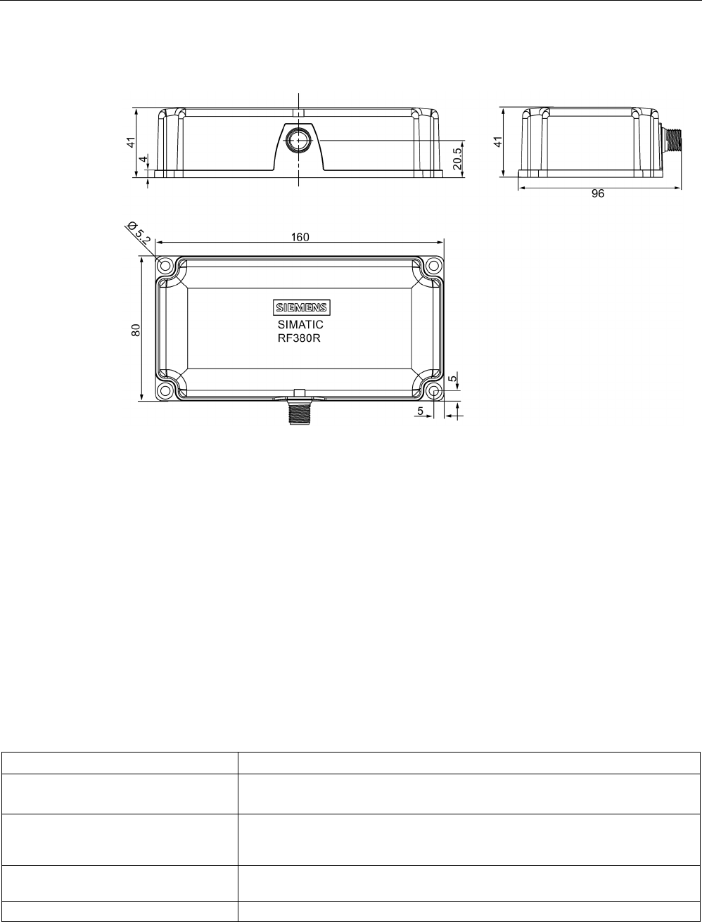
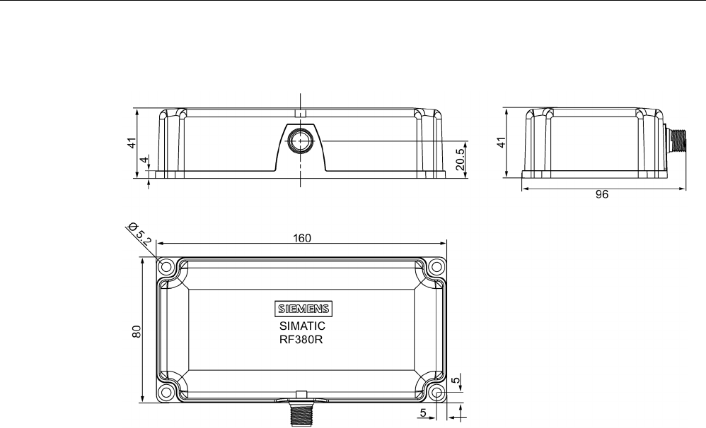
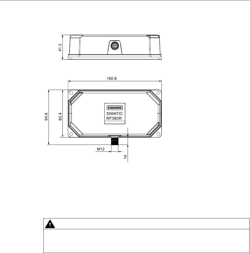
5.6.10
Dimension drawing
Figure 5-26 Dimension drawing RF380R
Dimensions in mm
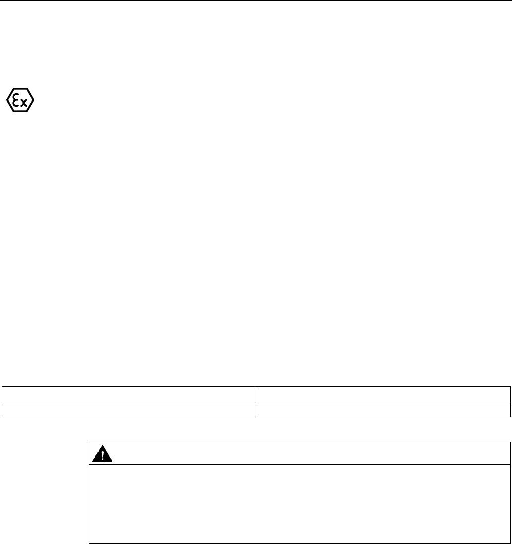
5.6.11
Use of the reader in a hazardous
5.6.11.1
Use of the reader in a hazardous area
The TÜV SÜD Automotive GmbH as approved test center as well as the TÜV SÜD Product
Service GmbH as certification center, identification number 0123, as per Article 9 of the
Directive of the European Council of 23 March 1994 (94/9/EC), has confirmed the
compliance with the essential health and safety requirements relating to the design and
construction of equipment and protective systems intended for use in hazardous areas as
per Annex II of the Directive. The essential health and safety requirements are satisfied in
accordance with the following standards:
Document
Title
EN 60079-0: 2006
Electrical equipment for hazardous gas atmospheres -
Part 0: General requirements
EN 60079-15: 2005 Electrical equipment for hazardous gas atmospheres -
Part 15: Design, testing and identification of electrical equipment with type of
protection "n"
DIN VDE 0848-5: 2001
(in parts)
Safety in electrical, magnetic and electromagnetic fields -
Part 5: Explosion protection
ZLS SK 107.1
Central office of the states for safety; test components
Readers
5.6 SIMATIC RF380R
SIMATIC RF300
System Manual, 07/2017, C79000-G8976-C345-07 191
Identification
The identification of the electrical equipment as an enclosed unit is:
II 3G Ex nC IIB T5
-25°C to +70°C
Um=30 V DC
The equipment is assigned the following references:
XXXYYYZZZ
[= serial number, is assigned during production]
TPS 09 ATEX 1 459 X
[= certificate number]
"No use of the equipment in the vicinity of processes generating high charges"
"Do not disconnect plug on load"
5.6.11.2
Use of the reader in hazardous areas for gases
Temperature class grading for gases
The temperature class of the reader for hazardous areas depends on the ambient
temperature range:
Ambient temperature range
Temperature class
-25 °C to +70 °C
T5
WARNING
Ignitions of gas-air mixtures
When using the RF380R reader, check to ensure that the temperature class is observed in
respect of the requirements of the area of application
Non-compliance with the permitted temperature ranges while using the reader can lead to
ignitions of gas-air mixtures.

Readers
5.6 SIMATIC RF380R
SIMATIC RF300
192 System Manual, 07/2017, C79000-G8976-C345-07
5.6.11.3
Installation and operating conditions for hazardous areas:
NOTICE
Explosion hazard
Risk of explosion of gas-air mixtures and the device can be damaged. Note the following
conditions when installing and operating the device in a hazardous area:
• Making and breaking of circuits is permitted only in a de-energized state.
• The maximum surface temperature, corresponding to the marking, applies only for
operation without a cover of dust.
• The device may only be operated in such a way that adequate protection against UV
light is ensured.
• The device may not be operated in areas influenced by processes that generate high
electrostatic charges.
• The device must be installed so that it is mechanically protected.
• The grounding of the plug (8-pin) on the reader must be via its supply cable.
• The device may only be operated with accessories specified or supplied by the
manufacturer. All the points above also apply to the accessories (cables and
connectors) and to the antennas (exception: the housing of ANT 1 does not need to be
installed with impact protection).
• The device sockets incl. the metal parts of the connecting cable must have a shrink-on
sleeve pulled over them, in other words, all metal parts apart from the securing sockets
of the housing must be fully covered and be inaccessible.
• After disconnecting the connections (antenna cable, signal/supply cable), before the
plugs are inserted again, they must be checked for contamination and if necessary
cleaned.
Readers
5.7 SIMATIC RF380R with Scanmode
SIMATIC RF300
System Manual, 07/2017, C79000-G8976-C345-07 193
5.7
SIMATIC RF380R with Scanmode
You will find detailed information on the SIMATIC RF382R with Scanmode on the Industry
Online Support - SIMATIC RF380R with Scanmode
(https://support.industry.siemens.com/cs/ww/en/ps/15037).
5.7.1
Features
RF380R Scanmode
Characteristics
Design ① RS-232 or RS-422 interface
②
Status display
Area of application Identification tasks on assembly lines in
harsh industrial environments
5.7.2
Ordering data for RF380R with Scanmode
Table 5- 28 Ordering data RF380R Scanmode
Product
Article number
RF380R Scanmode
6GT2801-3AB20-0AX1

Readers
5.7 SIMATIC RF380R with Scanmode
SIMATIC RF300
194 System Manual, 07/2017, C79000-G8976-C345-07
5.7.3
Pin assignment RF380R Scanmode RS-232 interface
You can connect the RF380R Scanmode reader via the internal RS-232/RS-422 interface to
a higher-level system. (See section "Basic rules (Page 111)") Make sure that the pin
assignment is correct. In the factory settings, the reader is set to RS-232. Siemens can
change the interface to RS-422.
Table 5- 29 Connector and reader pin assignment
Pin
Pin
Device end 8-pin
M12
Assignment
RS-232
RS-422
1
+ 24 V
+ 24 V
2 RXD - Transmit
3
0 V
0 V
4
TXD
+ Transmit
5
not used
+ Receive
6
not used
- Receive
7
not used
not used
8
Ground (shield)
Ground (shield)
5.7.4
LED operating display
The operational statuses of the reader are displayed by the LEDs. The LED can adopt the
colors green, red or yellow and the statuses off , on , flashing :
Table 5- 30 LED operating display on the reader
LED
Meaning
The reader is turned off.
Operating voltage present, reader ready for operation
• Operating mode "with presence": Transponder present
• Operating mode "without presence": Transponder present and command currently
being executed
There is an error. The number of flashes provides information about the current error.
You will find more information on error messages in the section "System diagnostics
(Page 413)".
5.7.5
Ensuring reliable data exchange
The "center point" of the transponder must be situated within the transmission window.
Readers
5.7 SIMATIC RF380R with Scanmode
SIMATIC RF300
System Manual, 07/2017, C79000-G8976-C345-07 195
5.7.6
Metal-free area
The RF380R can be flush-mounted in metal. Allow for a possible reduction in the field data.
Figure 5-27 Metal-free area for RF380R
To avoid any impact on the field data, the distance a should be ≥ 20 mm.
5.7.7
Minimum distance between several RF380R Scanmode readers
RF380R side by side
D
≥ 400 mm (with 2 readers)
D
≥ 500 mm (with more than 2 readers)
Figure 5-28 Minimum distance between RF380R readers

Readers
5.7 SIMATIC RF380R with Scanmode
SIMATIC RF300
196 System Manual, 07/2017, C79000-G8976-C345-07
RF380R face-to-face
D
≥ 800 mm
Figure 5-29 Face-to-face distance between two RF380R
5.7.8
Technical specifications
Table 5- 31 Technical specifications of the RF380R Scanmode reader
6GT2801-3AB20-0AX1
Product type designation
SIMATIC RF380R Scanmode
Radio frequencies
Operating frequency, rated value
13.56 MHz
Electrical data
Maximum range
200 mm
Maximum data transmission speed
reader ↔ transponder
RF300 transponder ISO transponder
• Read approx. 8000 bytes/s approx. 1500 bytes/s
Transmission speed
9.6, 19.2, 38.4, 57, 115.2 kBd
Read distances of the reader See section "Field data for transponders, readers
and antennas (Page 51)."
MTBF (Mean Time Between Failures)
109 years
Interfaces
Electrical connector design
M12, 8-pin
Standard for interfaces for communication RS-232 / RS-422
Antenna
integrated
Mechanical specifications
Enclosure
• Material • Plastic PA 12
• Color • Anthracite
Recommended distance to metal
0 mm

Readers
5.7 SIMATIC RF380R with Scanmode
SIMATIC RF300
System Manual, 07/2017, C79000-G8976-C345-07 197
6GT2801-3AB20-0AX1
Supply voltage, current consumption, power loss
Supply voltage
24 VDC
Typical current consumption
160 mA
Permitted ambient conditions
Ambient temperature
• During operation -25 to +70 °C
• During transportation and storage -40 to +85 °C
Degree of protection to EN 60529
IP67
Shock-resistant to EN 60721-3-7, Class 7 M3
500 m/s
2
Vibration-resistant to EN 60721-3-7, Class 7 M3
200 m/s
2
Torsion and bending load
Not permitted
Design, dimensions and weights
Dimensions (L x W x H)
160 x 80 x 41 (without M12 device connector)
Weight
Approx. 600 g
Type of mounting 4 x M5 screws;
1.5 Nm
Cable length for RS-422 interface, maximum
RS-422
RS-232
1000 m
30 m
LED display design
3-color LED
Standards, specifications, approvals
Proof of suitability Radio to R&TTE directives EN 300330,
EN 301489, CE, FCC, UL/CSA
5.7.9
Approvals
FCC information
Siemens SIMATIC RF380R (MLFB 6GT2801-3AB20-0AX1); FCC ID NXW-RF380R01
This device complies with part 15 of the FCC rules. Operation is subject to the following two
conditions:
(1) This device may not cause harmful interference, and
(2) this device must accept any interference received, including interference that may cause
undesired operation.

Readers
5.7 SIMATIC RF380R with Scanmode
SIMATIC RF300
198 System Manual, 07/2017, C79000-G8976-C345-07
Caution
Any changes or modifications not expressly approved by the party responsible for
compliance could void the user's authority to operate the equipment.
Note
This equipment has been tested and found to comply with the limits for a Class A digital
device, pursuant to part 15 of the FCC Rules.
These limits are designed to provide reasonable protection against harmful interference
when the equipment is operated in a commercial environment. This equipment generates,
uses, and can radiate radio frequency energy and, if not installed and used in accordance
with the instruction manual, may cause harmful interference to radio communications.
Operation of this equipment in a residential area is likely to cause harmful interference in
which case the user will be required to correct the interference at his own expense.
IC information
This device complies with Industry Canada licence-exempt RSS standard(s). Operation is
subject to the following two conditions:
(1) This device may not cause interference, and
(2) this device must accept any interference, including interference that may cause
undesired operation of the device.
Le présent appareil est conforme aux CNR d`Industrie Canada applicables aux appareils
radio exempts de licence. L`exploitation est autorisée aux deux conditions suivantes :
(1) L`appareil ne doit pas produire de brouillage, et
(2) l'utilisateur de l`appareil doit accepter tout brouillage radioélectrique subi, même si le
brouillage est susceptible d`en compromettre le fonctionnement.
5.7.10
Certificates and Approvals
Certificates for USA and Canada
Underwriters Laboratories (UL) acc. to standard UL 60950, Report E11 5352 and Ca-
nadian standard C22.2 No. 60950 (I.T.E) or acc. to UL508 and C22.2 No. 142
(IND.CONT.EQ)
Readers
5.7 SIMATIC RF380R with Scanmode
SIMATIC RF300
System Manual, 07/2017, C79000-G8976-C345-07 199
5.7.11
Dimension drawing
Figure 5-30 Dimension drawing RF380R
Dimensions in mm
Readers
5.8 SIMATIC RF380R - 2nd generation
SIMATIC RF300
200 System Manual, 07/2017, C79000-G8976-C345-07
5.8
SIMATIC RF380R - 2nd generation
5.8.1
Features
SIMATIC RF380R
Characteristics
Design ① RS-232 or RS-422 interface
②
Status display
Area of application Identification tasks on assembly lines in
harsh industrial environments
5.8.2
RF380R ordering data
Table 5- 32 RF380R ordering data
Article number
RF380R with RS-232/RS-422 interface (3964R)
6GT2801-3BA10
Readers
5.8 SIMATIC RF380R - 2nd generation
SIMATIC RF300
System Manual, 07/2017, C79000-G8976-C345-07 201
5.8.3
Pin assignment of RF380R RS-232/RS-422 interface
You can connect the RF380R reader to a higher-level system via the internal RS-422
interface or via the RS-232 interface. After connection, the interface module automatically
detects which interface has been used.
Note correct assignment of the pins here:
Pin
Pin
Device end
8-pin M12
Assignment
RS-232
RS-422
1
+ 24 V
+ 24 V
2 RXD - Transmit
3
0 V
0 V
4
TXD
+ Transmit
5
not used
+ Receive
6
not used
- Receive
7
not used
not used
8
Ground (shield)
Ground (shield)
5.8.4
LED operating display
The operational statuses of the reader are displayed by two LEDs. The LEDs can adopt the
colors white green, red, yellow or blue and the statuses off , on , flashing :
Table 5- 33 Display elements
LED
Meaning
The reader is turned off.
The reader is turned on and is searching for transponders.
The reader is in the "Setup" mode, in the "Search for transponders" status and
has not yet received a "RESET" command and is not ready.
/ There is transponder in the antenna field.
The reader is in the "Setup" mode, in the status "Show quality", has not yet re-
ceived a "RESET" command and is not ready.
Depending on the signal strength, the LED flickers or is lit permanently.
The reader has received a "RESET" command.
The reader is turned on, the antenna is turned off.
• Operating mode "with presence": Transponder present
• Operating mode "without presence": Transponder present and command
currently being executed
There is an error. The number of flashes provides information about the current
error.
You will find more information on error messages in the section "System diag-
nostics (Page 413)".
Readers
5.8 SIMATIC RF380R - 2nd generation
SIMATIC RF300
202 System Manual, 07/2017, C79000-G8976-C345-07
5.8.5
Ensuring reliable data exchange
The "center point" of the transponder must be situated within the transmission window.
5.8.6
Metal-free area
Figure 5-31 Metal-free space for RF380R - 2nd generation
The RF380R can be flush-mounted in metal. Allow for a possible reduction in the field data.
To avoid any impact on the field data, the distance a should be ≥ 20 mm.
Readers
5.8 SIMATIC RF380R - 2nd generation
SIMATIC RF300
System Manual, 07/2017, C79000-G8976-C345-07 203
5.8.7
Minimum distance between RF380R readers
RF380R side by side
D
≥ 400 mm (with 2 readers)
D
≥ 500 mm (with more than 2 readers)
Figure 5-32 Minimum distance between multiple RF380R - 2nd generation
RF380R face-to-face
D
≥ 800 mm
Figure 5-33 Face-of-face distance between two RF380R - 2nd generation

Readers
5.8 SIMATIC RF380R - 2nd generation
SIMATIC RF300
204 System Manual, 07/2017, C79000-G8976-C345-07
5.8.8
Technical specifications
Table 5- 34 Technical specifications of the RF380R reader
6GT2801-3BA10
Product type designation
SIMATIC RF380R
Radio frequencies
Operating frequency, rated value
13.56 MHz
Electrical data
Maximum range
240 mm
Maximum data transmission speed
reader ↔ transponder
RF300
tran-
sponder
ISO tran-
sponder
(MDS D)
ISO transponder
(MDS E)
• Read • ≤ 8000
bytes/s
• ≤ 3300
bytes/s
• ≤ 3400
bytes/s
• Write • ≤ 8000
bytes/s
• ≤ 1700
bytes/s
• ≤ 800
bytes/s
Transmission speed
19.2, 57.6, 115.2 kBd
Read/write distances of the reader See section "Field data for transponders, readers
and antennas (Page 51)."
MTBF (Mean Time Between Failures)
172.6 years
Interfaces
Electrical connector design
M12, 8-pin
Standard for interfaces for communication
RS-232/RS-422 (3964R protocol)
Antenna
integrated
Mechanical specifications
Enclosure
• Material • Plastic PA 12
• Color • Anthracite
Recommended distance to metal
0 mm
Supply voltage, current consumption, power loss
Supply voltage
24 VDC
Typical current consumption
130 mA
Permitted ambient conditions
Ambient temperature
• During operation • -25 to +70 ℃

Readers
5.8 SIMATIC RF380R - 2nd generation
SIMATIC RF300
System Manual, 07/2017, C79000-G8976-C345-07 205
6GT2801-3BA10
• During transportation and storage • -40 to +85 ℃
Degree of protection to EN 60529
IP67
Shock-resistant to EN 60721-3-7, Class 7 M3
500 m/s
2
Vibration-resistant to EN 60721-3-7, Class 7 M3
200 m/s
2
Torsion and bending load
Not permitted
Design, dimensions and weights
Dimensions (L x W x H)
160 x 80 x 41 mm
Weight
600 g
Type of mounting 4 x M5 screws;
1.5 Nm
Cable length for RS-422 interface, maximum
RS-422
RS-232
1000 m
30 m
LED display design
2 LEDs, 5 colors
Standards, specifications, approvals
Proof of suitability Radio in accordance with R&TTE directives EN
300330,
EN 301489, CE, FCC, UL/CSA,
Ex: II 3G Ex nC IIB T4
5.8.9
Approvals
FCC information
Siemens SIMATIC RF380R (MLFB 6GT2801-3BA10); FCC ID NXW-RF380R02
This device complies with part 15 of the FCC rules. Operation is subject to the following two
conditions:
(1) This device may not cause harmful interference, and
(2) this device must accept any interference received, including interference that may cause
undesired operation.
Caution
Any changes or modifications not expressly approved by the party responsible for
compliance could void the user's authority to operate the equipment.

Readers
5.8 SIMATIC RF380R - 2nd generation
SIMATIC RF300
206 System Manual, 07/2017, C79000-G8976-C345-07
Note
This equipment has been tested and found to comply with the limits for a Class A digital
device, pursuant to part 15 of the FCC Rules.
These limits are designed to provide reasonable protection against harmful interference
when the equipment is operated in a commercial environment. This equipment generates,
uses, and can radiate radio frequency energy and, if not installed and used in accordance
with the instruction manual, may cause harmful interference to radio communications.
Operation of this equipment in a residential area is likely to cause harmful interference in
which case the user will be required to correct the interference at his own expense.
IC information
This device complies with Industry Canada licence-exempt RSS standard(s). Operation is
subject to the following two conditions:
(1) This device may not cause interference, and
(2) this device must accept any interference, including interference that may cause
undesired operation of the device.
Le présent appareil est conforme aux CNR d`Industrie Canada applicables aux appareils
radio exempts de licence. L`exploitation est autorisée aux deux conditions suivantes :
(1) L`appareil ne doit pas produire de brouillage, et
(2) l'utilisateur de l`appareil doit accepter tout brouillage radioélectrique subi, même si le
brouillage est susceptible d`en compromettre le fonctionnement.
Readers
5.8 SIMATIC RF380R - 2nd generation
SIMATIC RF300
System Manual, 07/2017, C79000-G8976-C345-07 207
5.8.10
Dimension drawing
Figure 5-34 Dimension drawing SIMATIC RF380R - 2nd generation
Dimensions in mm
5.8.11
Using the reader in hazardous area
WARNING
Explosion hazard
In a flammable or combustible environment, no cables may be connected to or
disconnected from the device.
Readers
5.8 SIMATIC RF380R - 2nd generation
SIMATIC RF300
208 System Manual, 07/2017, C79000-G8976-C345-07
ATEX
The SIMATIC Ident products meet the requirements of explosion protection acc. to ATEX.
The products meet the requirements of the standards:
Document
Title
EN 60079-0 Hazardous areas
Part 0: Equipment - General requirements
EN 60079-7 Hazardous areas
Part 7: Equipment protection by increased safety "e"
EN 60079-31 Potentially explosive atmosphere
Part 31: Equipment dust ignition protection by enclosure "t"
You will find the current versions of the standards in the currently valid ATEX certificates.
ATEX mark
NOTICE
Validity only when the devices are marked
There is a corresponding approval only with devices to which the Ex mark is applied.
The identification of the electrical equipment as an enclosed unit is:
II 3 G Ex ec IIB T4 Gc
II 3 D Ex tc IIIC T80°C Dc
-25 °C ... +70 °C
U
n
= 24 VDC
The equipment also has the following additional information:
XXXYYYZZZ
[= serial number, is assigned during production]
DEMKO 17 ATEX 1767 X
[= certificate number]

Readers
5.8 SIMATIC RF380R - 2nd generation
SIMATIC RF300
System Manual, 07/2017, C79000-G8976-C345-07 209
IECEx
The SIMATIC Ident products meet the requirements of explosion protection acc. to IECEx.
The products meet the requirements of the standards:
Document
Title
IEC 60079-0 Hazardous areas
Part 0: Equipment - General requirements
IEC 60079-7 Hazardous areas
Part 7: Equipment protection by increased safety "e"
IEC 60079-31 Potentially explosive atmosphere
Part 31: Equipment dust ignition protection by enclosure "t"
You will find the current versions of the standards in the currently valid IECEx certificates.
IECEx mark
NOTICE
Validity only when the devices are marked
There is a corresponding approval only with devices to which the IECEx mark is applied.
The identification of the electrical equipment as an enclosed unit is:
II 3 G Ex ec IIB T4 Gc
II 3 D Ex tc IIIC T80°C Dc
-25 °C ... +70 °C
U
n= 24 VDC
The equipment also has the following additional information:
XXXYYYZZZ
[= serial number, is assigned during production]
IECEx ULD 17.0031 X
[= certificate number]
UL HAZ. LOC.
The SIMATIC Ident products meet the requirements of explosion protection acc. to UL HAZ.
LOC. The products meet the requirements of the standards:
Document
Title
UL 60079-0
Hazardous areas
Part 0: Equipment - General requirements
CSA C22.2 NO. 60079-0
UL 60079-7
Hazardous areas
Part 7: Equipment protection by increased safety "e"
CSA C22.2 NO. 60079-7
UL 60079-31
Potentially explosive atmosphere
Part 31: Equipment dust ignition protection by enclosure "t"
CSA C22.2 NO. 60079-31
Readers
5.8 SIMATIC RF380R - 2nd generation
SIMATIC RF300
210 System Manual, 07/2017, C79000-G8976-C345-07
You will find the current versions of the standards in the currently valid UL HAZ. LOC.
certificates
UL HAZ. LOC. mark
NOTICE
Validity only when the devices are marked
There is a corresponding approval only with devices to which the UL HAZ. LOC. mark is
applied.
The identification of the electrical equipment as an enclosed unit is:
E223122
IND.CONT.EQ FOR HAZ.LOC.
CL.I, DIV.2, GP.C,D T4
CL.II, DIV.2, GP.F,G T80°C
AEx ec IIB T4, Ex ec IIB T4
AEx tc IIIC T80°C, Ex tc IIIC T80°C
-25 °C ... +70 °C
U
n
= 24 VDC
The equipment also has the following additional information:
XXXYYYZZZ
[= serial number, is assigned during production]
5.8.11.1
Using the reader in hazardous area for gases
The temperature class of the reader for hazardous areas depends on the ambient
temperature range:
Ambient temperature range
Temperature class
-25 ℃ ... +70 ℃
T4
WARNING
Ignitions of gas-air mixtures
When using the reader, check to make sure that the temperature class is adhered to in
keeping with the requirements of the area of application
Non-compliance with the permitted temperature ranges while using the reader can lead to
ignitions of gas-air mixtures.
Readers
5.8 SIMATIC RF380R - 2nd generation
SIMATIC RF300
System Manual, 07/2017, C79000-G8976-C345-07 211
5.8.11.2
Using the reader in hazardous area for dust
The equipment is suitable for dusts whose ignition temperatures for a dust layer of 5 mm are
higher than 80 °C (smoldering temperature).
Ambient temperature range
Temperature value
-25 °C < Ta < +70 °C
T80 °C
WARNING
Ignitions of dust-air mixtures
When using the reader, check to make sure that the temperature values are adhered to in
keeping with the requirements of the area of application. Non-
compliance with the permitted
temperature range while using the reader can lead to ignitions of dust-air mixtures.
5.8.11.3
Installation and operating conditions for hazardous areas:
NOTICE
Risk of explosion
Risk of explosion of dust-air mixtures or gas-air mixtures and the device can be damaged.
Note the following conditions when installing and operating the device in a hazardous area:
• Making and breaking of circuits is permitted only in a de-energized state.
• The maximum surface temperature, corresponding to the marking, applies only for
operation without a cover of dust.
• The device may only be operated in such a way that adequate protection against UV
light is ensured.
• The device may not be operated in areas influenced by processes that generate high
electrostatic charges.
• The device must be installed so that it is mechanically protected.
• The grounding of the plug (8-pin) on the reader must be via its supply cable.
• The device may only be operated with accessories specified or supplied by the
manufacturer. All the points above also apply to the accessories (cables and
connectors) and to the antennas (exception: the housing of ANT 1 does not need to be
installed with impact protection).
• The device sockets incl. the metal parts of the connecting cable must have a shrink-on
sleeve pulled over them, in other words, all metal parts apart from the securing sockets
of the housing must be fully covered and be inaccessible.
• After disconnecting the connections (antenna cable, signal/supply cable), before the
plugs are inserted again, they must be checked for contamination and if necessary
cleaned.
Readers
5.9 SIMATIC RF382R with Scanmode
SIMATIC RF300
212 System Manual, 07/2017, C79000-G8976-C345-07
5.9
SIMATIC RF382R with Scanmode
You will find detailed information on the SIMATIC RF382R with Scanmode on the Internet
(https://support.industry.siemens.com/cs/ww/en/ps/15038).
5.9.1
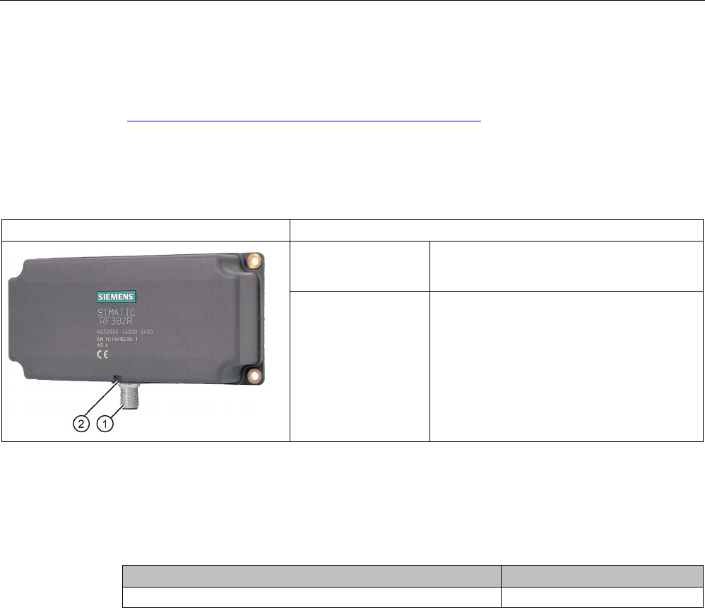
Characteristics
RF382R Scanmode
Characteristics
Design ① RS-232 or RS-422 interface
②
Status display
Operating range Suitable for high speeds, e.g. in
• Suspension conveyor systems
• Assembly lines
• Production
• Order picking
5.9.2
RF382R with Scanmode ordering data
Table 5- 35 RF382R Scanmode ordering data
Article number
RF382R Scanmode
6GT2801-3AB20-0AX0
Readers
5.9 SIMATIC RF382R with Scanmode
SIMATIC RF300
System Manual, 07/2017, C79000-G8976-C345-07 213
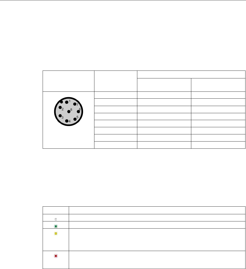
5.9.3
Pin assignment RF382R Scanmode RS232 interface
You can connect the RF382R Scanmode reader via the internal RS-232/RS-422 interface or
via a higher-level system. (See section "Basic rules (Page 111)") Make sure that the pin
assignment is correct. In the factory settings, the reader is set to RS-232. Siemens can
change the interface to RS-422.
Table 5- 36 Connector and reader pin assignment
Pin
Pin
Device end 8-pin
M12
Assignment
RS-232
RS-422
1
+ 24 V
+ 24 V
2 RXD - Transmit
3
0 V
0 V
4
TXD
+ Transmit
5
not used
+ Receive
6
not used
- Receive
7
not used
not used
8
Ground (shield)
Ground (shield)
5.9.4
LED operating display
The operational statuses of the reader are displayed by the LEDs. The LED can adopt the
colors green, red or yellow and the statuses off , on , flashing :
Table 5- 37 LED operating display on the reader
LED
Meaning
The reader is turned off.
Operating voltage present, reader ready for operation
• Operating mode "with presence": Transponder present
• Operating mode "without presence": Transponder present and command currently
being executed
There is an error. The number of flashes provides information about the current error.
You will find more information on error messages in the section "System diagnostics
(Page 413)".
5.9.5
Ensuring reliable data exchange
The "center point" of the transponder must be situated within the transmission window.
Readers
5.9 SIMATIC RF382R with Scanmode
SIMATIC RF300
214 System Manual, 07/2017, C79000-G8976-C345-07
5.9.6
Mounting on metal
The RF382R can be mounted directly on metal. Flush mounting on metal is not permitted.
5.9.7
Minimum distance between several RF382R Scanmode readers
Figure 5-35 Minimum distance between several RF382R Scanmode readers
Minimum distance D from RF382R to RF382R
D ≥ 200 mm
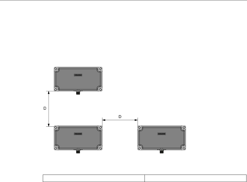
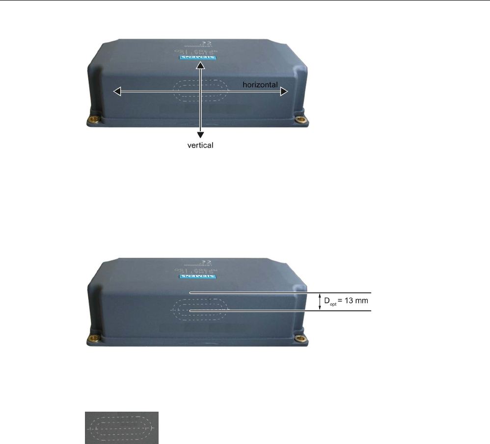
5.9.8
Transmission window
Orientation of fields of the SIMATIC RF382R Scanmode
For many applications it may be best to operate the reader so that the tags move from left to
right (or from right to left) at a certain distance in front of the narrow edge of the reader. With
this direction of movement, the horizontal reader field is used, see figure below.
You also have the option of moving the tags up and down (or down and up) past the narrow
edge of the reader. With this direction of movement, uses the vertical reader field is used.
Readers
5.9 SIMATIC RF382R with Scanmode
SIMATIC RF300
System Manual, 07/2017, C79000-G8976-C345-07 215
Figure 5-36 Definition of horizontal and vertical reader field
Maximum field strength
The reader creates the maximum field approximately 13 mm below the upper reader edge.
For the largest possible reading range the tags you want to read should move in this range.
This applies regardless of whether the horizontal or the vertical field is used.
Figure 5-37 Line of maximum magnetic field strength
The area of the maximum field strength and, therefore, the maximum range is identified by a
laser icon:
Figure 5-38 Laser labeling
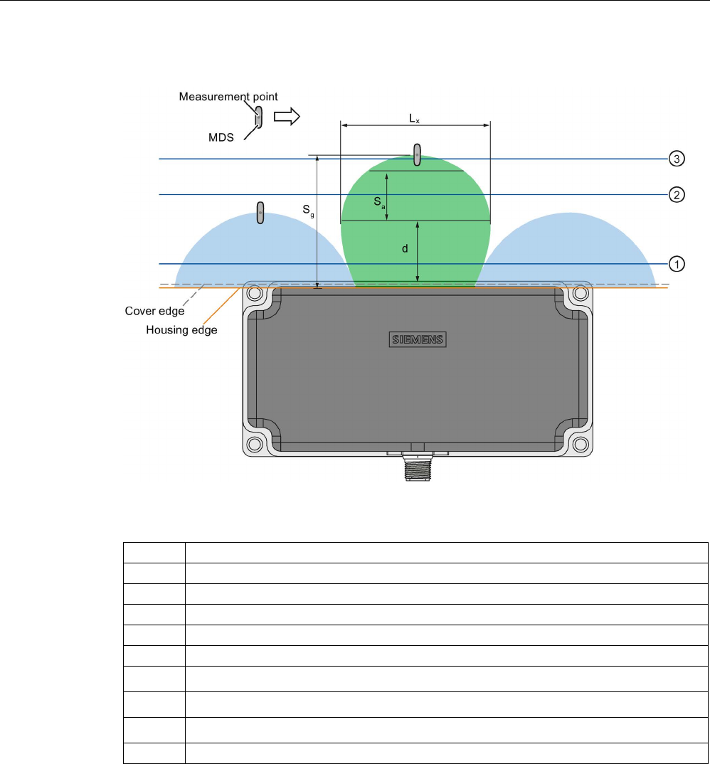
Readers
5.9 SIMATIC RF382R with Scanmode
SIMATIC RF300
216 System Manual, 07/2017, C79000-G8976-C345-07
Transmission window horizontal field
Figure 5-39 Distance definition horizontal field
Green
Main field (processing field)
Blue
Secondary fields, horizontal field
L
x
Maximum length of the main field, horizontal field
d
Distance from the reader edge at which maximum horizontal main field length L exists
S
a
Operating range in the main field
Sg
Limit distance
①
Level 1
②
Level 2
③
Level 3
⇒
Direction of motion of the transponder
Operating range (Sa)
The operating range lies between Level ① and Level ③.
The operating range between Levels ① and ② includes secondary fields.
The recommended operating range therefore lies in the green main field between Level 2
and Level 3.
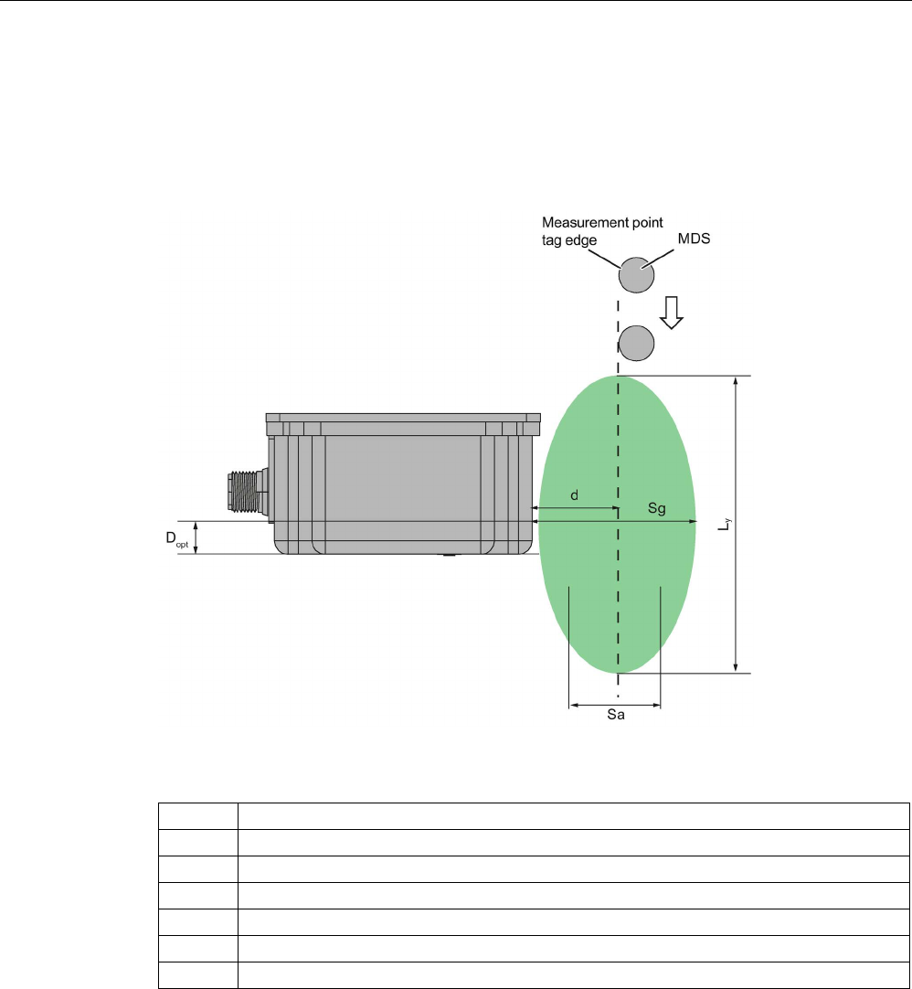
Readers
5.9 SIMATIC RF382R with Scanmode
SIMATIC RF300
System Manual, 07/2017, C79000-G8976-C345-07 217
Limit distance (Sg)
The limit distance lies on Level ③.
Transmission window vertical field
Figure 5-40 Distance definition vertical field
Green
Main field (processing field)
Ly
Maximum length of the main field, vertical field
d
Distance from the reader edge at which maximum vertical main field length L
y
exists
Sa
Operating range in the main field
S
g
Limit distance
Dopt
= 13 mm
⇓
Direction of motion of the transponder

Readers
5.9 SIMATIC RF382R with Scanmode
SIMATIC RF300
218 System Manual, 07/2017, C79000-G8976-C345-07
5.9.9
Technical specifications
Table 5- 38 Technical specifications of the RF382R reader with Scanmode
6GT2801-3AB20-0AX0
Product type designation
SIMATIC RF382R Scanmode
Radio frequencies
Operating frequency, rated value
13.56 MHz
Electrical data
Maximum range
75 mm
Maximum data transmission speed
reader ↔ transponder
ISO transponder
• Read • approx. 1500 bytes/s
Transmission speed
19.2, 57.6, 115.2 kBd
Read/write distances of the reader See section "Field data for transponders, readers
and antennas (Page 51)."
MTBF (Mean Time Between Failures)
115 years
Interfaces
Electrical connector design
M12, 8-pin
Standard for interfaces for communication RS-232 (factory setting, can be changed to RS-
422)
Antenna
integrated
Mechanical specifications
Enclosure
• Material • Plastic PA 12
• Color • Anthracite
Recommended distance to metal 0 mm
Supply voltage, current consumption, power loss
Supply voltage 24 VDC
Typical current consumption
140 mA
Permitted ambient conditions
Ambient temperature
• During operation • -25 to +70 ℃
• During transportation and storage • -40 to +85 ℃
Degree of protection to EN 60529
IP67
Shock-resistant to EN 60721-3-7, Class 7 M3
500 m/s
2

Readers
5.9 SIMATIC RF382R with Scanmode
SIMATIC RF300
System Manual, 07/2017, C79000-G8976-C345-07 219
6GT2801-3AB20-0AX0
Vibration-resistant to EN 60721-3-7, Class 7 M3
200 m/s
2
Torsion and bending load
Not permitted
Design, dimensions and weights
Dimensions (L x W x H)
160 x 80 x 41 mm
Weight
550 g
Type of mounting 4 x M5 screws;
1.5 Nm
Cable length for RS-422 interface, maximum
RS-422
RS-232
1000 m
30 m
LED display design
3-color LED
Standards, specifications, approvals
Proof of suitability Radio to R&TTE directives EN 300330,
EN 301489, CE, FCC, UL/CSA
5.9.10
Approvals
FCC information
Siemens SIMATIC RF382R (MLFB 6GT2801-3AB20-0AX0); FCC ID NXW-RF382R
This device complies with part 15 of the FCC rules. Operation is subject to the following two
conditions:
(1) This device may not cause harmful interference, and
(2) this device must accept any interference received, including interference that may cause
undesired operation.
Caution
Any changes or modifications not expressly approved by the party responsible for
compliance could void the user's authority to operate the equipment.
Note
This equipment has been tested and found to comply with the limits for a Class A digital
device, pursuant to part 15 of the FCC Rules.
These limits are designed to provide reasonable protection against harmful interference
when the equipment is operated in a commercial environment. This equipment generates,
uses, and can radiate radio frequency energy and, if not installed and used in accordance
with the instruction manual, may cause harmful interference to radio communications.
Operation of this equipment in a residential area is likely to cause harmful interference in
which case the user will be required to correct the interference at his own expense.
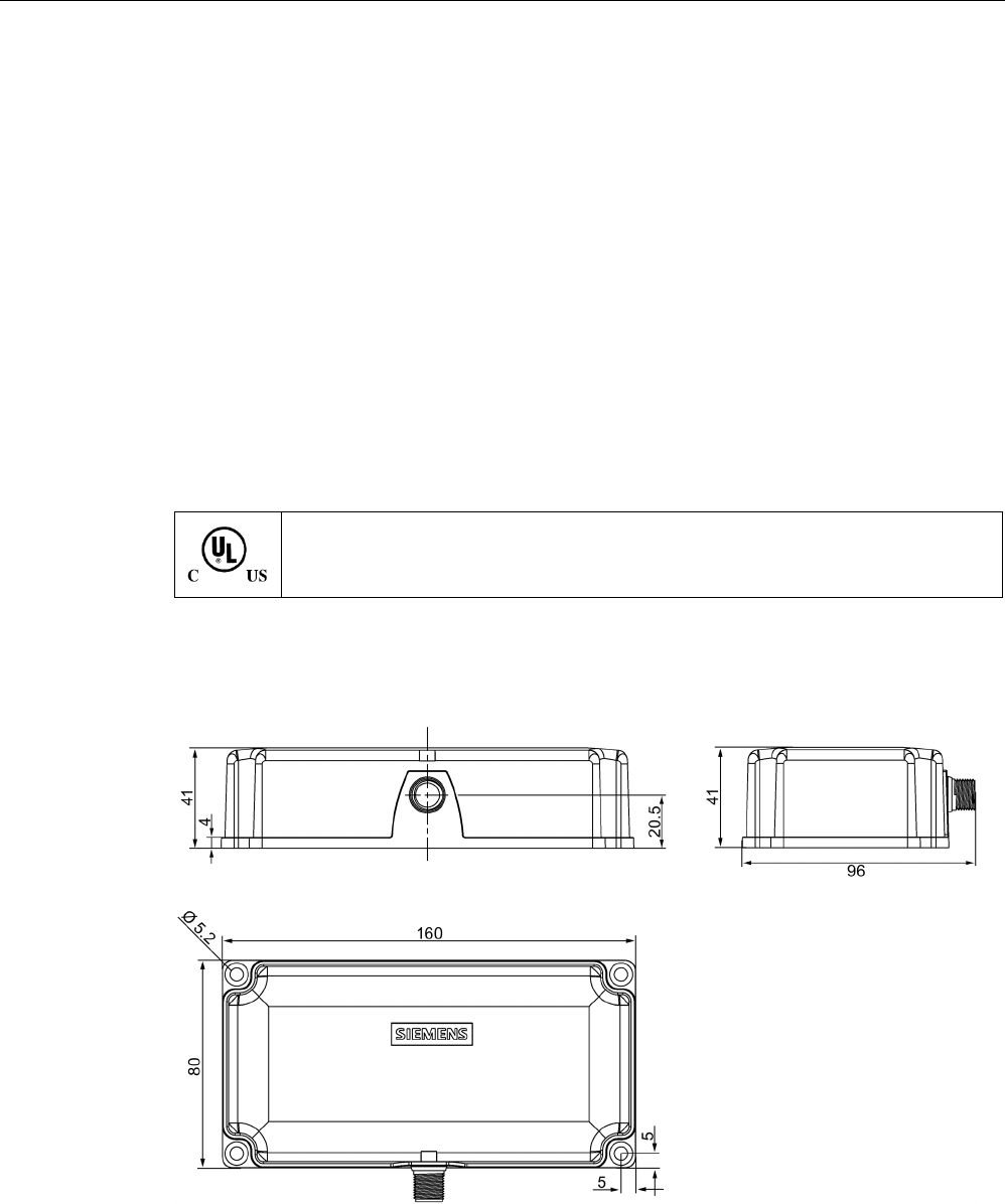
Readers
5.9 SIMATIC RF382R with Scanmode
SIMATIC RF300
220 System Manual, 07/2017, C79000-G8976-C345-07
IC information
This device complies with Industry Canada licence-exempt RSS standard(s). Operation is
subject to the following two conditions:
(1) This device may not cause interference, and
(2) this device must accept any interference, including interference that may cause
undesired operation of the device.
Le présent appareil est conforme aux CNR d`Industrie Canada applicables aux appareils
radio exempts de licence. L`exploitation est autorisée aux deux conditions suivantes :
(1) L`appareil ne doit pas produire de brouillage, et
(2) l'utilisateur de l`appareil doit accepter tout brouillage radioélectrique subi, même si le
brouillage est susceptible d`en compromettre le fonctionnement.
Certificates for USA and Canada
Underwriters Laboratories (UL) acc. to standard UL 60950, Report E11 5352 and Ca-
nadian standard C22.2 No. 60950 (I.T.E) or acc. to UL508 and C22.2 No. 142
(IND.CONT.EQ)
5.9.11
Dimensional diagram
Figure 5-41 Dimension drawing
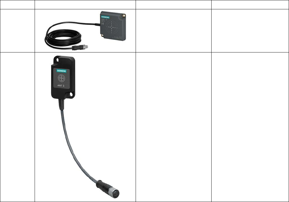
SIMATIC RF300
System Manual, 07/2017, C79000-G8976-C345-07 221
Antennas
6
6.1
Features
For the RF350R and RF350M readers, you can use the following plug-in antennas:
Antenna
Product photo
Limit distance Sg 1)
Dimensions
ANT 1
Up to 140 mm 75 x 75 x 20 mm
(L x W x H)
ANT 3
Up to 50 mm 50 x 75 x 10 mm
(L x W x H)
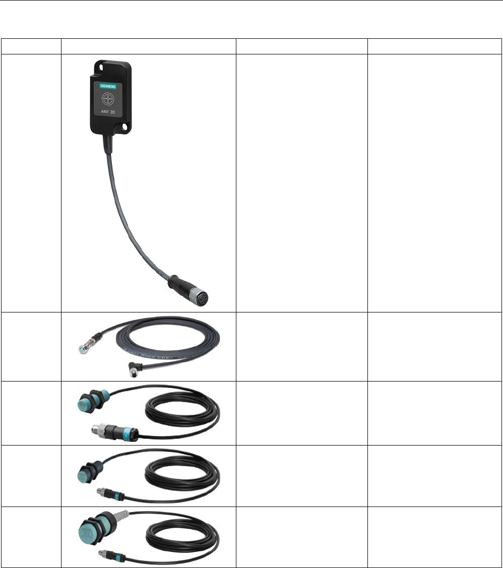
Antennas
6.1 Features
SIMATIC RF300
222 System Manual, 07/2017, C79000-G8976-C345-07
Antenna
Product photo
Limit distance Sg 1)
Dimensions
ANT 3S
Up to 5 mm 50 × 28 × 10 mm
(L x W x H)
ANT 8 2)
Up to 4 mm M8 x 1.0 x 39 mm
(∅ x thread x L)
ANT 12
Up to 16 mm M12 x 1.0 x 40 mm
(∅ x thread x L)
ANT 18
Up to 35 mm M18 x 1.0 x 55 mm
(Ø x thread x L)
ANT 30
Up to 55 mm M30 x 1.5 x 61 mm
(Ø x thread x L)
1)
Depending on the transponder used
2) only released with RF350M und RF350R - second generation

Antennas
6.1 Features
SIMATIC RF300
System Manual, 07/2017, C79000-G8976-C345-07 223
Note
Use of the antennas in hazardous areas
The antennas ANT 1, ANT 12, ANT 18 and ANT 30 are approved for use in hazardous
locations. For more information, refer to the section "
Use of the reader in hazardous areas
(Page
163)".
ANT 1
The ANT 1 is an antenna in the mid performance range and can be used to the customer's
advantage in production and assembly lines due to its manageable housing shape. The
antenna dimensions make it possible to read/write large quantities of data dynamically
from/to the transponder during operation. The antenna cable can be plugged in.
ANT 3
The ANT 3 is designed for use in small assembly lines. The extremely compact design of the
antenna allows extremely accurate positioning. The antenna cable can be plugged in.
ANT 3S
Due to its slimline and compact design, the ANT 3S can still be precisely positioned in
cramped conditions. Areas of application are, for example, tool identification. The antenna
cable can be plugged in.
ANT 8
The ANT 8 is primarily envisaged for tool identification applications. The extremely small
design of the antenna allows extremely accurate positioning. The antenna cable can be
connected at the reader end and screwed to the antenna.
The antenna ANT 8 has currently only been tested and released for use in conjunction with
the mobile reader RF350M and the reader RF350R - second generation.
ANT 12
The ANT 12 is primarily envisaged for tool identification applications. The very small size of
the antenna means that highly exact positioning is possible using the plastic nuts included in
the scope of delivery. The antenna cable can be plugged in.
ANT 18
The ANT 18 is designed for use in small assembly lines. Due to its small, compact
construction, the antenna can be easily positioned for any application using two plastic nuts
(included in the package). The antenna cable can be connected at the reader end.
Antennas
6.2 Ordering data
SIMATIC RF300
224 System Manual, 07/2017, C79000-G8976-C345-07
ANT 30
The ANT 30 is designed for use in small assembly lines. In comparison to ANT 18, the
maximum write/read distance is approximately 60 % larger. Due to its compact construction,
the antenna can be easily positioned for any application using two plastic nuts (included in
the package). The antenna cable can be connected at the reader end.
6.2
Ordering data
Table 6- 1 Ordering data for antennas
Article number
ANT 1
incl. integrated antenna cable 3 m
6GT2398-1CB00
ANT 3 without antenna connecting cable 6GT2398-1CD30-0AX0
incl. plug-in antenna cable 3 m
6GT2398-1CD40-0AX0
ANT 3S
without antenna connecting cable
6GT2398-1CD50-0AX0
incl. plug-in antenna cable 3 m
6GT2398-1CD60-0AX0
ANT 8
without antenna connecting cable
6GT2398-1CF00
incl. plug-in antenna cable 3 m
6GT2398-1CF10
ANT 12
incl. plug-in antenna cable 3 m
6GT2398-1CC00
ANT 18
incl. plug-in antenna cable 3 m
6GT2398-1CA00
ANT 30
incl. plug-in antenna cable 3 m
6GT2398-1CD00
Table 6- 2 Antenna accessories ordering data
Article number
Antenna connecting cable
3 m
6GT2398-0AH30
6.3
Ensuring reliable data exchange
The "center point" of the transponder must be situated within the transmission window.
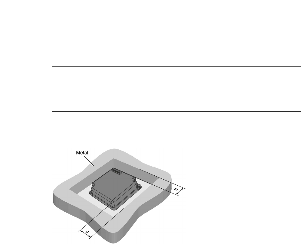
Antennas
6.4 Metal-free area
SIMATIC RF300
System Manual, 07/2017, C79000-G8976-C345-07 225
6.4
Metal-free area
The antennas ANT 1, ANT 8, ANT 12, ANT 18 and ANT 30 can be flush-mounted in metal.
Please allow for a possible reduction in the field data values. During installation, maintain the
minimum distances (a and b) on/flush with the metal.
Note
Reduction of range if the metal-free space is not maintained
At values lower than a
and b, the field data changes significantly, resulting in a reduction in
the limit distance and operating distance. Therefore, during installation, maintain the
minimum distances (a and b) on/flush with the metal.
Metal-free space for flush-mounted installation of ANT 1
a =
40 mm
Figure 6-1 ANT 1 flush-mounted in metal
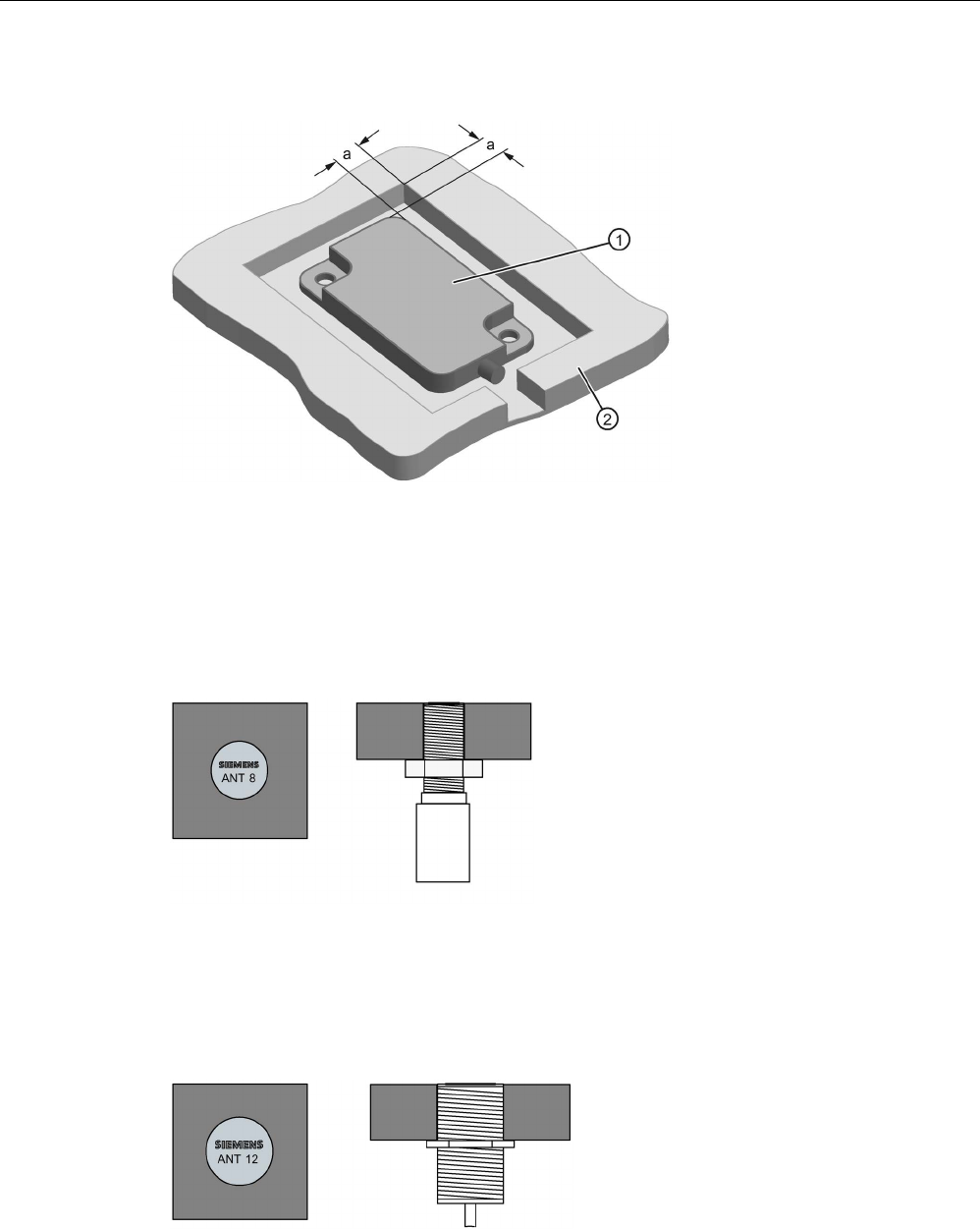
Antennas
6.4 Metal-free area
SIMATIC RF300
226 System Manual, 07/2017, C79000-G8976-C345-07
Metal-free space for flush-mounted installation of ANT 3 and ANT 3S
①
ANT 3
②
Metal
a
= 10 mm
Figure 6-2 ANT 3 and ANT 3S flush-mounted in metal
Flush-mounting of ANT 8
Figure 6-3 ANT 8 flush-mounted in metal
The ANT 8 can be flush-mounted in metal.
Flush-mounting of ANT 12
Figure 6-4 ANT 12 flush-mounted in metal
The ANT 12 can be flush-mounted in metal.
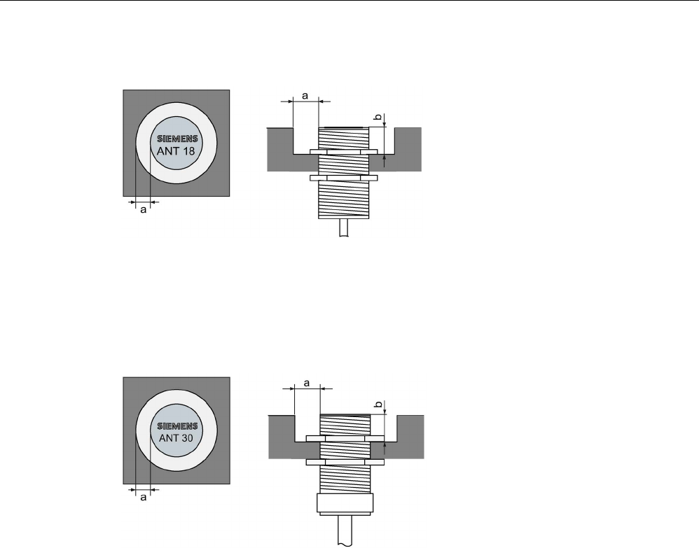
Antennas
6.4 Metal-free area
SIMATIC RF300
System Manual, 07/2017, C79000-G8976-C345-07 227
Metal-free space for flush-mounted installation of ANT 18
a =
10 mm
b =
10 mm
Figure 6-5 ANT 18 flush-mounted in metal
Metal-free space for flush-mounted installation of ANT 30
a =
20 mm
b =
20 mm
Figure 6-6 ANT 30 flush-mounted in metal
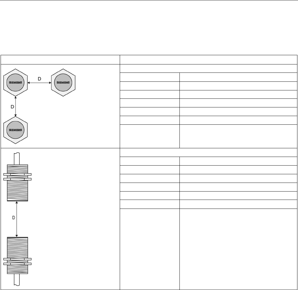
Antennas
6.5 Minimum distance between antennas
SIMATIC RF300
228 System Manual, 07/2017, C79000-G8976-C345-07
6.5
Minimum distance between antennas
Table 6- 3 Minimum distance between antennas
Diagram (example)
Minimum distance [mm]
Antennas next to each other
ANT 1 D ≥ 300 mm
ANT 3
D ≥ 150 mm
ANT 3S D ≥ 20 mm
ANT 8
D ≥ 50 mm
ANT 12
D ≥ 70 mm
ANT 18
D ≥ 100 mm
ANT 30 D ≥ 100 mm
Antennas face to face
ANT 1
D ≥ 500 mm
ANT 3
D ≥ 200 mm
ANT 3S
D ≥ 50 mm
ANT 8
D ≥ 50 mm
ANT 12
D ≥ 100 mm
ANT 18
D ≥ 100 mm
ANT 30 D ≥ 200 mm
The reader electronics can be mounted directly alongside each other.

Antennas
6.6 Technical specifications
SIMATIC RF300
System Manual, 07/2017, C79000-G8976-C345-07 229
6.6
Technical specifications
Table 6- 4 Technical specifications of the antennas ANT 1, ANT 3 , ANT 3S and ANT 8
ANT 1
ANT 3
ANT 3S
ANT 8
Max. write/read distance
antenna ↔ transponder (S
g
)
140 mm 50 mm 5 mm 4 mm
Housing dimensions 75 x 75 x 20 mm
(L x W x H)
50 x 28 x 10 mm
(L x W x H)
50 x 28 x 10 mm
(L x W x H)
M8 x 1.0 x 39 mm
(Ø x thread x L)
Color
Anthracite
Black
Black
silver-metallic
Material Plastic
PA 12
Plastic
PA6-V0
Plastic
PA6-V0
Stainless steel
Plug connection M8, 4-pin;
(pins on antenna
side)
M8, 4-pin;
socket on antenna
side
M8, 4-pin;
socket on antenna
side
M8, 4-pin;
(pins on antenna
side)
Degree of protection to EN
60529
IP67 IP67 (front)
Shock-resistant acc. to
EN 60721-3-7, Class 7M21)
Vibration-resistant to
EN 60721-3-7, Class 7M2
1)
500 m/s2
200 m/s
2
(3...50 Hz)
Attachment of the antenna 2 x M5 screws 2 x M4 screws 2 x M4 screws 2x stainless steel
nuts
M8 x 1.0 mm
Ambient temperature
• During operation
• During transportation
and storage
• -25 ℃ ... +70 ℃
• -40 °C ... +85 °C
Approx. weight
• without antenna cable
• with antenna cable
(3.0 m)
• --
• 225 g
• 35 g
• 160 g
• 35 g
• 160 g
• 10 g
• 140 g
1) Warning: The values for shock and vibration are maximum values and must not be applied continuously.
Table 6- 5 Technical specifications of the antennas ANT 12, ANT 18 and ANT 30
ANT 12
ANT 18
ANT 30
Max. write/read distance
antenna ↔ transponder (S
g
)
16 mm 35 mm 55 mm
Housing dimensions M12 x 1.0 x 40 mm
(Ø x thread x L)
M18 x 1.0 x 55 mm
(Ø x thread x L)
M30 x 1.5 x 61 mm
(Ø x thread x L)
Color
Pale turquoise
Material Plastic
Crastin
Plug connection M8, 4-pin;
(pins on antenna side)
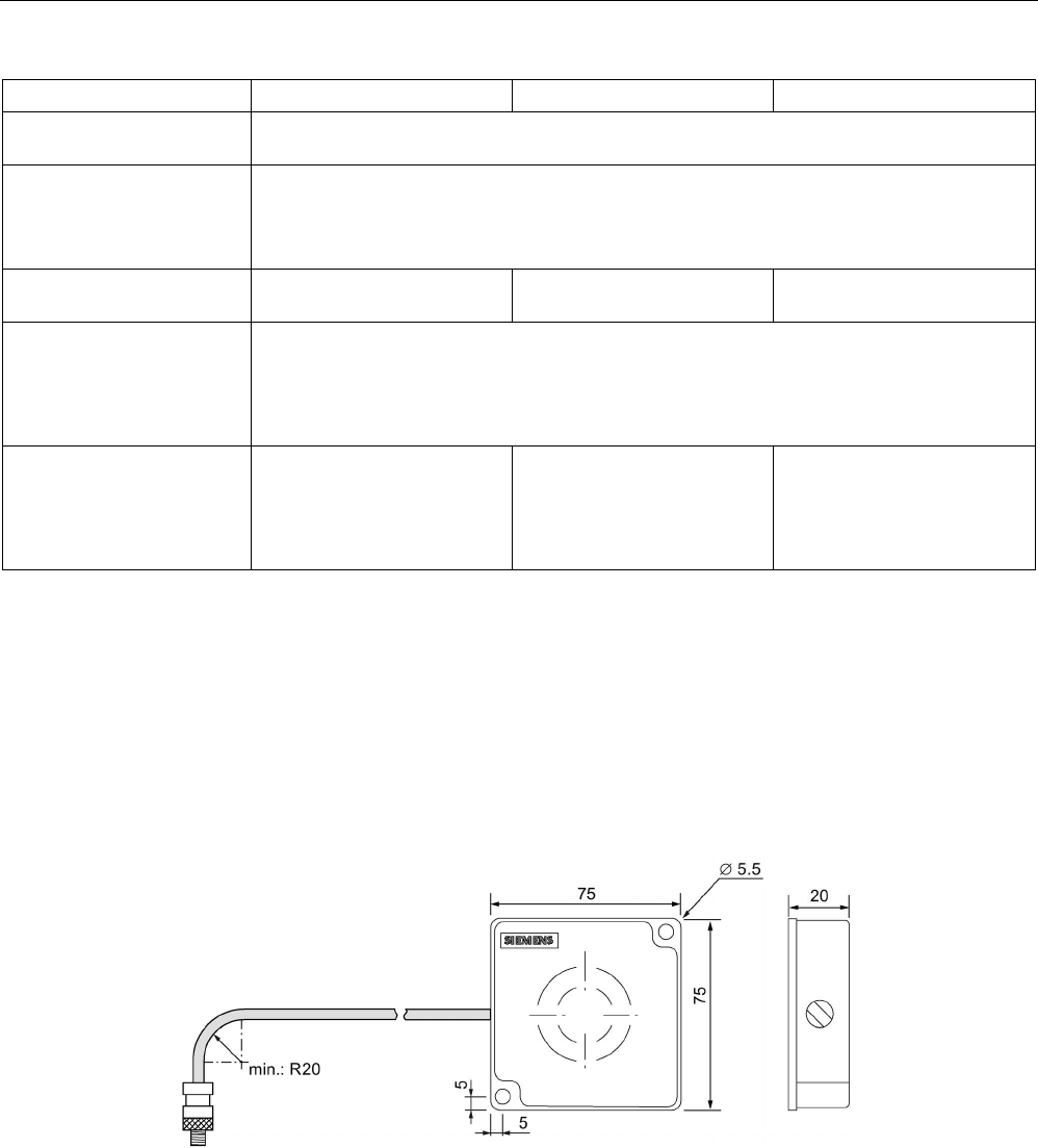
Antennas
6.7 Dimensional drawings
SIMATIC RF300
230 System Manual, 07/2017, C79000-G8976-C345-07
ANT 12
ANT 18
ANT 30
Degree of protection to EN
60529
IP67 (front)
Shock-resistant acc. to
EN 60721-3-7, Class 7M21)
Vibration-resistant to
EN 60721-3-7, Class 7M21)
500 m/s2
200 m/s2 (3...50 Hz)
Attachment of the antenna 2 plastic nuts
M12 x 1.0 mm
2 plastic nuts
M18 x 1.0 mm
2 plastic nuts
M30 x 1.5 mm
Ambient temperature
• During operation
• During transportation
and storage
• -25 ℃ ... +70 ℃
• -40 °C ... +85 °C
Approx. weight
• without antenna cable
• with antenna cable
(3.0 m)
• --
• 145 g
• --
• 130 g
• --
• 180 g
1) Warning: The values for shock and vibration are maximum values and must not be applied continuously.
6.7
Dimensional drawings
The cable length is 3 m. All dimensions are in mm.
ANT 1
Figure 6-7 Dimension drawing for ANT 1
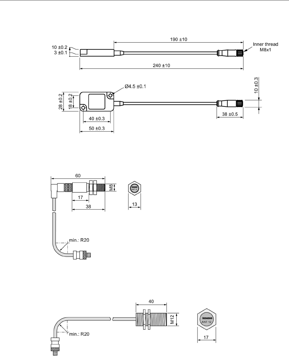
Antennas
6.7 Dimensional drawings
SIMATIC RF300
System Manual, 07/2017, C79000-G8976-C345-07 231
ANT 3 / ANT 3S
Figure 6-8 Dimension drawing ANT 3 7 ANT 3S
ANT 8
Figure 6-9 Dimension drawing for ANT 8
ANT 12
Figure 6-10 Dimension drawing for ANT 12
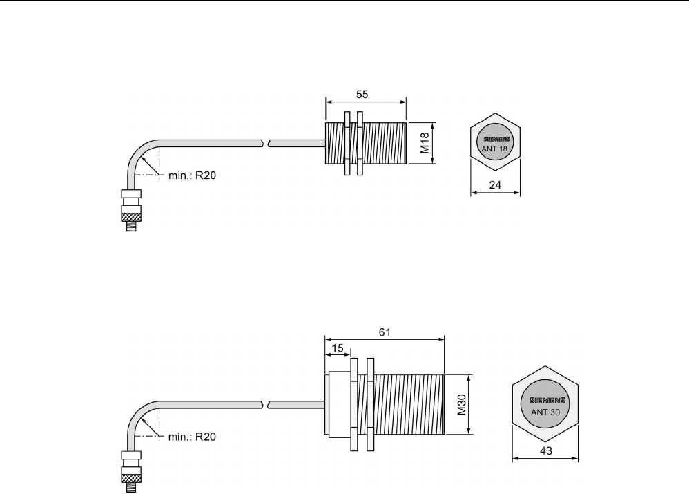
Antennas
6.7 Dimensional drawings
SIMATIC RF300
232 System Manual, 07/2017, C79000-G8976-C345-07
ANT 18
Figure 6-11 Dimension drawing for ANT 18
ANT 30
Figure 6-12 Dimension drawing for ANT 30
SIMATIC RF300
System Manual, 07/2017, C79000-G8976-C345-07 233
RF300 transponder
7
Features of the RF300 transponders
The RF300 transponders (RF3xxT) stand out particularly for their extremely fast data
exchange with the RF300 readers (RF3xxR). With the exception of the RF320T transponder,
all of the RF300 transponders have 8 to 64 KB of FRAM memory, which has an almost
unlimited capacity for reading and writing.
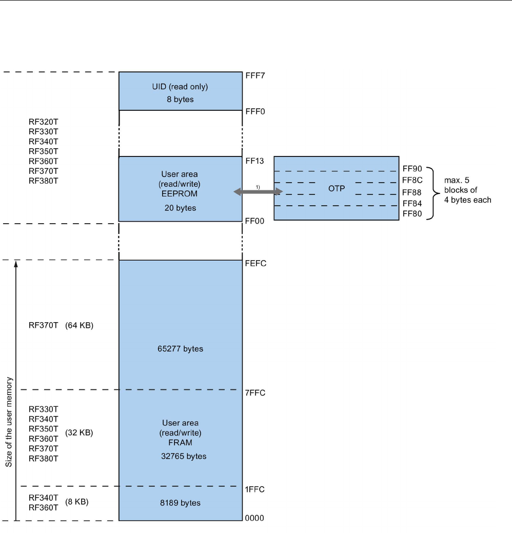
RF300 transponder
7.1 Memory configuration of the RF300 transponders
SIMATIC RF300
234 System Manual, 07/2017, C79000-G8976-C345-07
7.1
Memory configuration of the RF300 transponders
1) Physically identical memory When the OTP area is used, the corresponding user area (FF00-FF13) can no longer
be modified (read only).
Figure 7-1 Memory configuration of the RF300 transponders

RF300 transponder
7.1 Memory configuration of the RF300 transponders
SIMATIC RF300
System Manual, 07/2017, C79000-G8976-C345-07 235
EEPROM area
The memory configuration of an RF300 transponder always comprises an EEPROM that has
20 bytes for user data (read/write) and a 4-byte unique serial number (UID, read only). For
reasons of standardization, the UID is transferred as an 8 byte value through a read
command to address FFF0 with a length of 8. The unused 4 high bytes are filled with zeros.
Note
Write speed
The EEPROM user memory (address FF00
-FF13, or FF80-
FF90) requires significantly more
time for writing (approx. 11 ms/byte) than the high
-speed FRAM memory. For time-critical
applications with
write functions, it is advisable to use FRAM transponders (e.g. RF330T,
RF340T, RF350T, RF360T, RF370T, RF380T).
FRAM area
Depending on the tag type, high-speed FRAM memory is available. (8 KB, 32 KB, 64 KB).
This area does not exist for the RF320T.
In the case of RF3xxT transponders with FRAM memory, the data carrier initialization
command (INIT) is only effective on this memory area but not on the EEPROM area (FF00-
FF13).
OTP area
The EEPROM memory area (address FF00-FF13) can also be used as a so-called "OTP"
memory (One Time Programmable). The 5 block addresses FF80, FF84, FF88, FF8C and
FF90 are used for this purpose. A write command to this block address with a valid length (4,
8, 12, 16, 20 depending on the block address) protects the written data from subsequent
overwriting.
Note
Seamless use of the OTP area
When the OTP area is used, it must be ensured that the blocks are used starting from Block
0 consecutively.
Examples:
•
3 blocks (with write command), Block 0, 1, 2 (FF80, length = 12): valid
•
2 blocks (consecutive), Block 0 (FF80, length =4), Block 1 (FF84, length = 4): valid
•
2 blocks (consecutive), Block 0 (FF80, length =4), Block 2 (FF88, length = 4): Invalid
•
1 Block, Block 4 (FF90, length = 4): Invalid
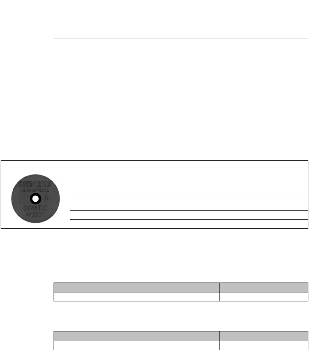
RF300 transponder
7.2 SIMATIC RF320T
SIMATIC RF300
236 System Manual, 07/2017, C79000-G8976-C345-07
Note
Use of the OTP area is not reversible
If you use the OPT area, you cannot undo it, because the OPT area can only be written to
once.
7.2
SIMATIC RF320T
7.2.1
Features
RF320T
Characteristics
Area of application Identification tasks on small assembly lines in harsh
industrial environments
Memory size
20 bytes of EEPROM user memory
Write/read range See section Field data of RF300 transponders
(Page 52)
Mounting on metal
Yes, with spacer
Degree of protection
IP67/IPx9K
7.2.2
Ordering data
Table 7- 1 Ordering data RF320T
Article number
RF320T
6GT2800-1CA00
Table 7- 2 Ordering data for RF320T accessories
Article number
Spacer
6GT2690-0AK00
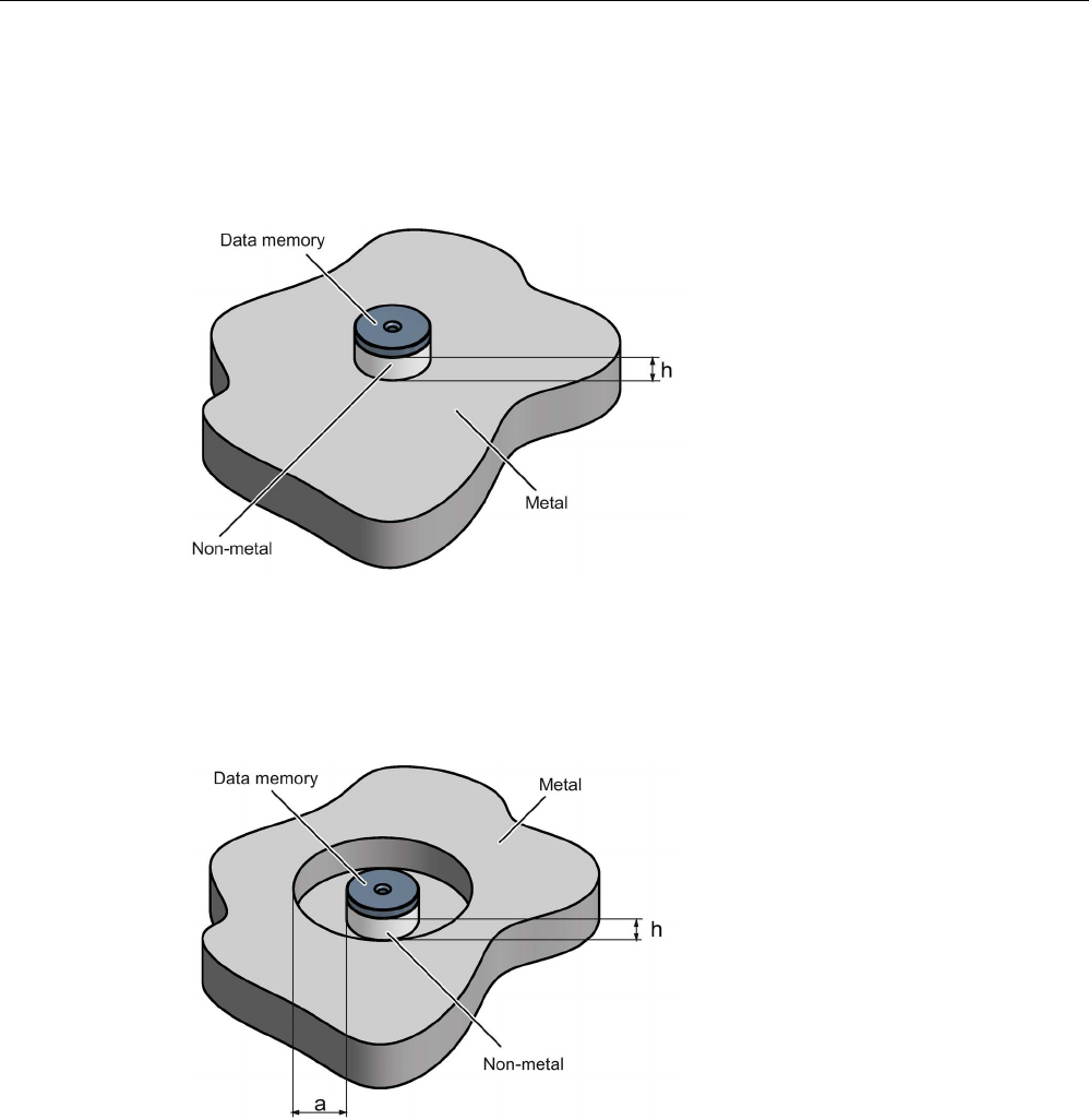
RF300 transponder
7.2 SIMATIC RF320T
SIMATIC RF300
System Manual, 07/2017, C79000-G8976-C345-07 237
7.2.3
Mounting on metal
Mounting on metal
h
≥ 15 mm
Figure 7-2 Mounting the MDS D124/D324/D424/D524/E624 and RF320T on metal with spacer
Flush-mounting
h
≥ 15 mm
a
≥ 25 mm
Figure 7-3 Flush-mounting of the MDS D124/D324/D424/D524/E624 and RF320T in metal with
spacer

RF300 transponder
7.2 SIMATIC RF320T
SIMATIC RF300
238 System Manual, 07/2017, C79000-G8976-C345-07
Note
Going below the distances
If the distances (a and h) are not observed, a reduction of the field data results. It is possible
to mount the MDS with metal screws (M3 countersunk head screws). This has
no tangible
impact on the range.
7.2.4
Technical data
Table 7- 3 Technical specifications for RF320T
6GT2800-1CA00
Product type designation
SIMATIC RF320T
Memory
Memory organization Byte-oriented, write protection possible in 4-byte
blocks
Memory configuration
• UID • 4 bytes EEPROM
• User memory • 20 bytes EEPROM
• OPT memory • 20 bytes EEPROM
Read cycles (at < 40 ℃)
> 10
14
Write cycles (at < 40 ℃)
> 10
5
Data retention time (at < 40 ℃)
> 10 years
Write/read distance (Sg) Dependent on the reader used, see section "Field
data of RF300 transponders (Page 52)"
MTBF (Mean Time Between Failures)
1800 years
Mechanical specifications
Enclosure
• Material • Epoxy resin
• Color • Black
Recommended distance to metal
≥ 20 mm
Power supply
Inductive, without battery
Permitted ambient conditions
Ambient temperature
• during write/read access • -25 to +125 ℃
• outside the read/write field • -40 ... +140 °C
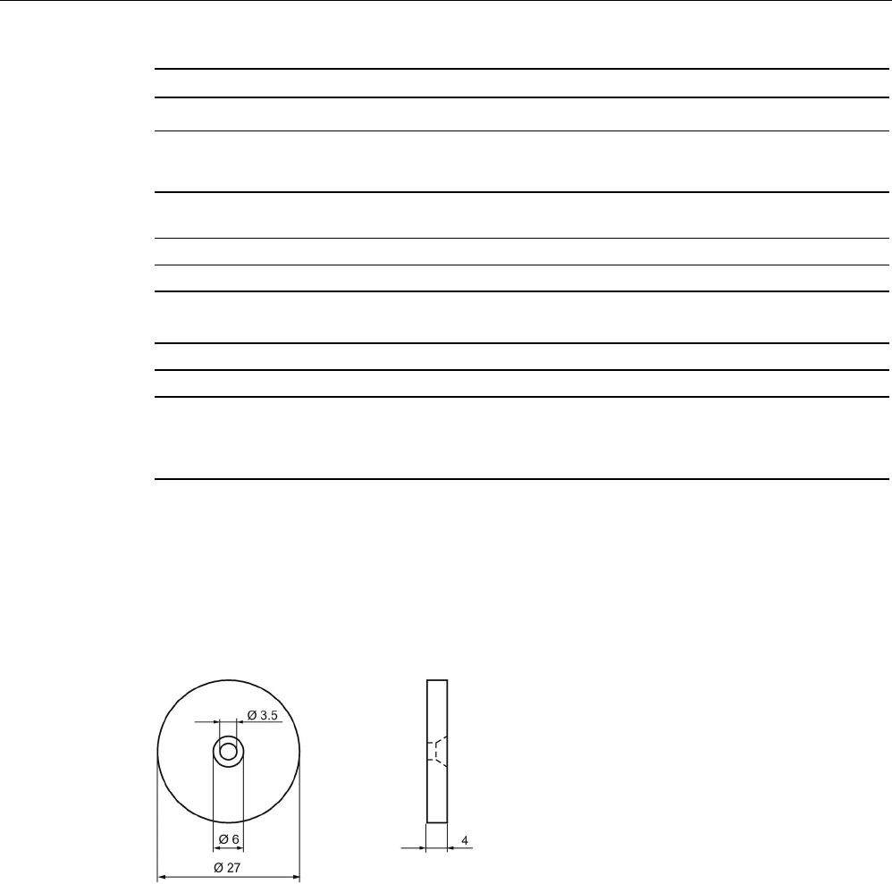
RF300 transponder
7.2 SIMATIC RF320T
SIMATIC RF300
System Manual, 07/2017, C79000-G8976-C345-07 239
6GT2800-1CA00
• during storage • -40 to +140 ℃
Degree of protection to EN 60529 • IP67
• IPx9K
Shock-resistant acc. toEN 60721-3-7, Class 7
M3
1)
1000 m/s2
Vibration-resistant to EN 60721-3-7, Class 7 M3
1)
200 m/s
2
Torsion and bending load
Not permitted
Design, dimensions and weights
Dimensions (Ø x H)
27 x 4 mm
Weight
5 g
Type of mounting • 1 x M3 screw 2)
≤ 1.0 Nm
• Glued 3)
1)
The values for shock and vibration are maximum values and must not be applied continuously.
2
) To prevent it loosening during operation, secure the screw with screw locking varnish.
3) The glue manufacturer's processing instructions must be observed.
7.2.5
Dimension drawing
Figure 7-4 RF320T dimension drawing
Dimensions in mm
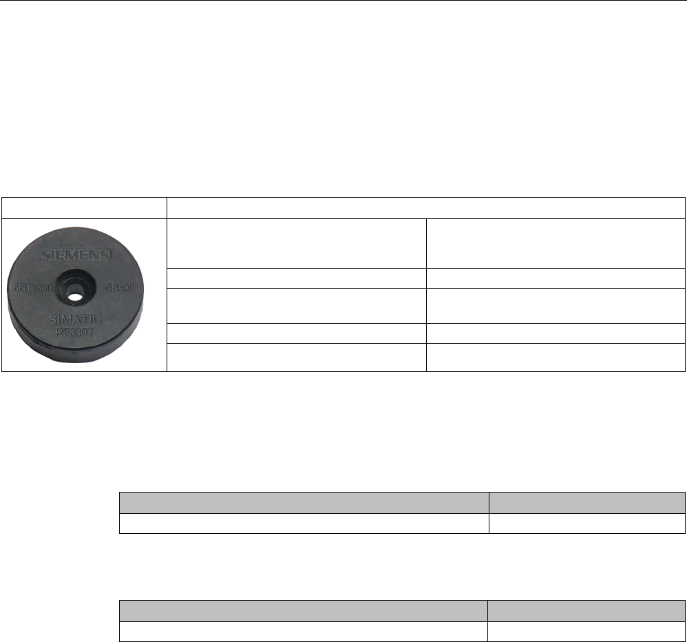
RF300 transponder
7.3 SIMATIC RF330T
SIMATIC RF300
240 System Manual, 07/2017, C79000-G8976-C345-07
7.3
SIMATIC RF330T
7.3.1
Features
Table 7- 4
RF330T
Characteristics
Area of application In production automation for identification of
metallic workpiece holders, workpieces or
containers.
Memory size 32 KB EEPROM user memory
Write/read range See section "Field data of RF300 transpond-
ers (Page 52)"
Mounting on metal
Yes flush mounted on/in metal
Degree of protection IP68/IPx9K
7.3.2
Ordering data
Table 7- 5 Ordering data RF330T
Article number
RF330T
6GT2800-5BA00
Table 7- 6 Ordering data for RF330T accessories
Article number
Fixing hood RF330T / MDS D423
6GT2690-0AE00
7.3.3
Mounting on/in metal
Direct mounting of the RF330T on metal is permitted.
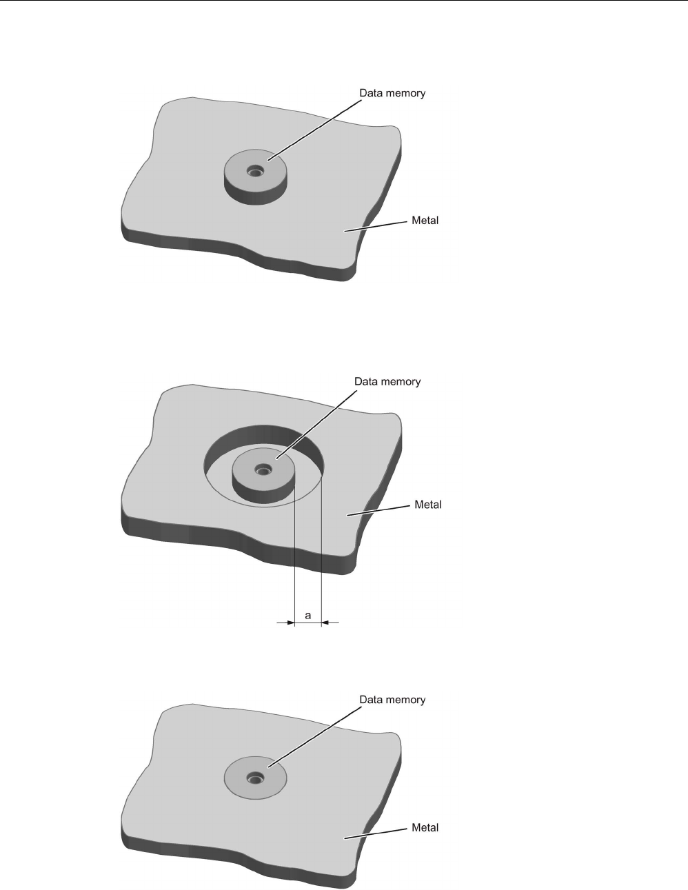
RF300 transponder
7.3 SIMATIC RF330T
SIMATIC RF300
System Manual, 07/2017, C79000-G8976-C345-07 241
Mounting of the RF330T on metal
Figure 7-5 Mounting of the RF330T on metal
Flush-mounting of RF330T in metal
a
≥ 10 mm
Figure 7-6 Mounting of the RF330T in metal with 10 mm clearance
Figure 7-7 Mounting of the RF330T in metal without clearance

RF300 transponder
7.3 SIMATIC RF330T
SIMATIC RF300
242 System Manual, 07/2017, C79000-G8976-C345-07
Note
Reduction of the write/read range
Note that when the device is flush
-mounted in metal without a surrounding clearance ≥ 10
mm, the write/read range is significantly
reduced.
7.3.4
Technical specifications
Table 7- 7 RF330T technical specifications
6GT2800-5BA00
Product type designation
SIMATIC RF330T
Memory
Memory organization
in bytes
Memory configuration
• UID • 4 bytes EEPROM
• User memory • 8 KB FRAM
• OPT memory • 20 bytes EEPROM
Read cycles (at < 40 ℃)
> 10
14
Write cycles (at < 40 ℃)
> 10
14
Data retention time (at < 40 ℃)
> 10 years
Write/read distance (Sg) Dependent on the reader used, see section "Field
data of RF300 transponders (Page 52)"
MTBF (Mean Time Between Failures)
1200 years
Mechanical specifications
Enclosure
• Material • Plastic PPS
• Color • Black
Recommended distance to metal
≥ 0 mm
Power supply
Inductive, without battery
Permitted ambient conditions
Ambient temperature
• during write/read access • -25 to +85 ℃
• outside the read/write field • -40 ... +100 °C
• during storage • -40 to +100 ℃
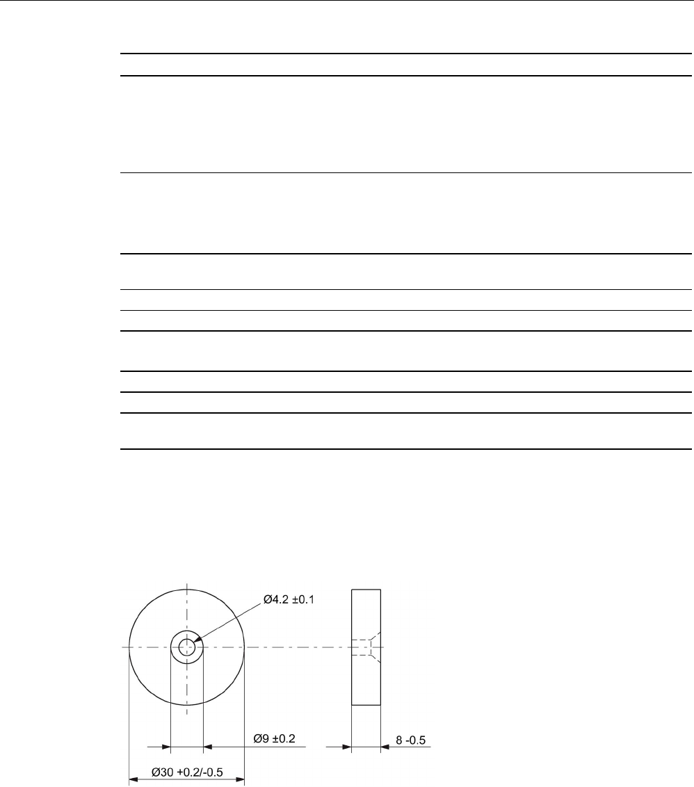
RF300 transponder
7.3 SIMATIC RF330T
SIMATIC RF300
System Manual, 07/2017, C79000-G8976-C345-07 243
6GT2800-5BA00
Degree of protection to EN 60529 • IP68
2 hours, 2 m, 20 ℃
• IPx9K
steam jet: 150 mm; 10 to 15 l/min; 100 bar; 75
°C
Pressure resistance • Low pressure resistant
vacuum dryer: up to 20 mbar
• high pressure resistant (see degree of protec-
tion IPx9K)
Shock-resistant acc. toEN 60721-3-7, Class 7
M3
1)
500 m/s2
Vibration-resistant to EN 60721-3-7, Class 7 M3
1)
200 m/s
2
Torsion and bending load
Not permitted
Design, dimensions and weights
Dimensions (Ø x H)
30 x 8 mm
Weight
10 g
Type of mounting 1 x M4 screw 2)
≤ 1.5 Nm
1)
The values for shock and vibration are maximum values and must not be applied continuously.
2 ) To prevent it loosening during operation, secure the screw with screw locking varnish.
7.3.5
Dimension drawing
Figure 7-8 RF330T dimension drawing
Dimensions in mm
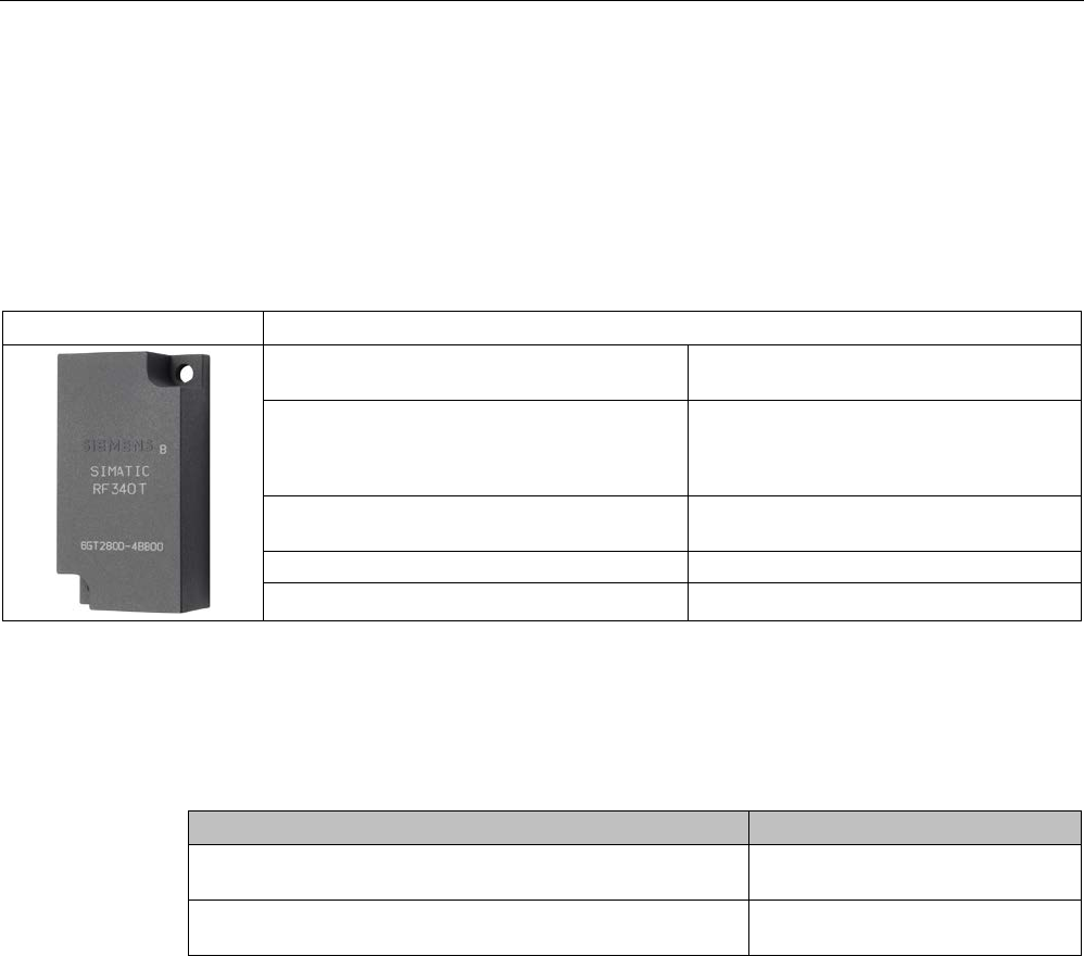
RF300 transponder
7.4 SIMATIC RF340T
SIMATIC RF300
244 System Manual, 07/2017, C79000-G8976-C345-07
7.4
SIMATIC RF340T
7.4.1
Features
Table 7- 8
RF340T
Characteristics
Area of application Identification tasks on small assembly lines
in harsh industrial environments
Memory size • 8 KB FRAM user memory
• 32 KB FRAM user memory
Write/read range See section Field data of RF300 tran-
sponders (Page 52)
Mounting on metal
Yes
Degree of protection IP68/IPx9K
7.4.2
Ordering data
Table 7- 9 Ordering data RF340T
Article number
RF340T
8 KB FRAM user memory
6GT2800-4BB00
RF340T
32 KB FRAM user memory
6GT2800-5BB00
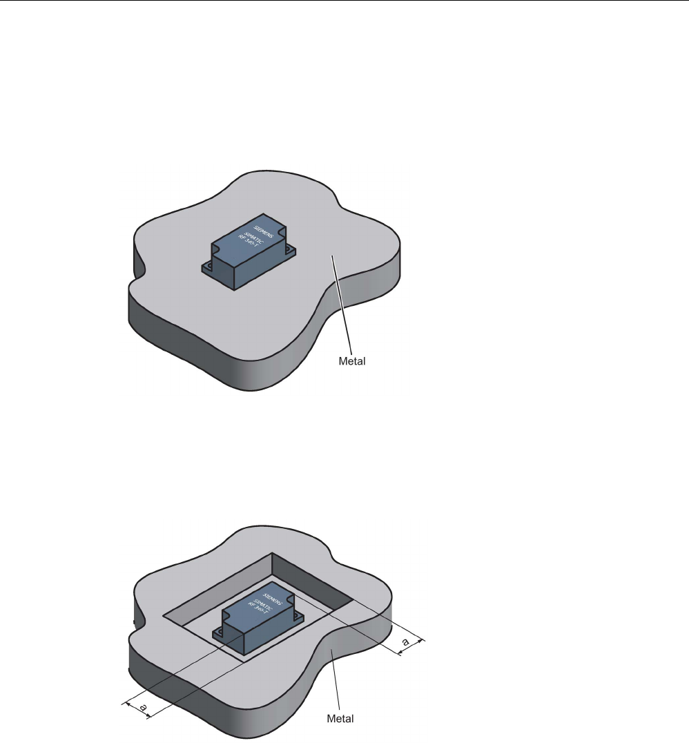
RF300 transponder
7.4 SIMATIC RF340T
SIMATIC RF300
System Manual, 07/2017, C79000-G8976-C345-07 245
7.4.3
Mounting on metal
Direct mounting of the RF340T on metal is permitted.
Mounting of RF340T on metal
Figure 7-9 Mounting of RF340T on metal
Flush-mounting of RF340T in metal:
Figure 7-10 Flush-mounting of RF340T in metal
The standard value for a is ≥ 20 mm. At lower values, the field data change significantly,
resulting in a reduction in the range.

RF300 transponder
7.4 SIMATIC RF340T
SIMATIC RF300
246 System Manual, 07/2017, C79000-G8976-C345-07
7.4.4
Technical specifications
Table 7- 10 Technical specifications for RF340T
6GT2800-4BB00
6GT2800-5BB00
Product type designation
SIMATIC RF340T
Memory
Memory organization
in bytes
Memory configuration
• UID • 4 bytes EEPROM
• User memory • 8 KB FRAM / 32 KB FRAM
• OPT memory • 20 bytes EEPROM
Read cycles (at < 40 ℃)
> 10
10
Write cycles (at < 40 ℃)
> 10
10
Data retention time (at < 40 ℃)
> 10 years
Write/read distance (Sg) Dependent on the reader used, see section "Field
data of RF300 transponders (Page 52)"
MTBF (Mean Time Between Failures)
1200 years
Mechanical specifications
Enclosure
• Material • Plastic PA 12
• Color • Anthracite
Recommended distance to metal
≥ 0 mm
Power supply
Inductive, without battery
Permitted ambient conditions
Ambient temperature
• during write/read access • -25 to +85 ℃
• outside the read/write field • -40 to +85 ℃
• during storage • -40 to +85 ℃
Degree of protection to EN 60529 • IP68
• IPx9K
Shock-resistant acc. toEN 60721-3-7, Class 7
M31)
500 m/s2
Vibration-resistant to EN 60721-3-7, Class 7 M31) 200 m/s2
Torsion and bending load Not permitted
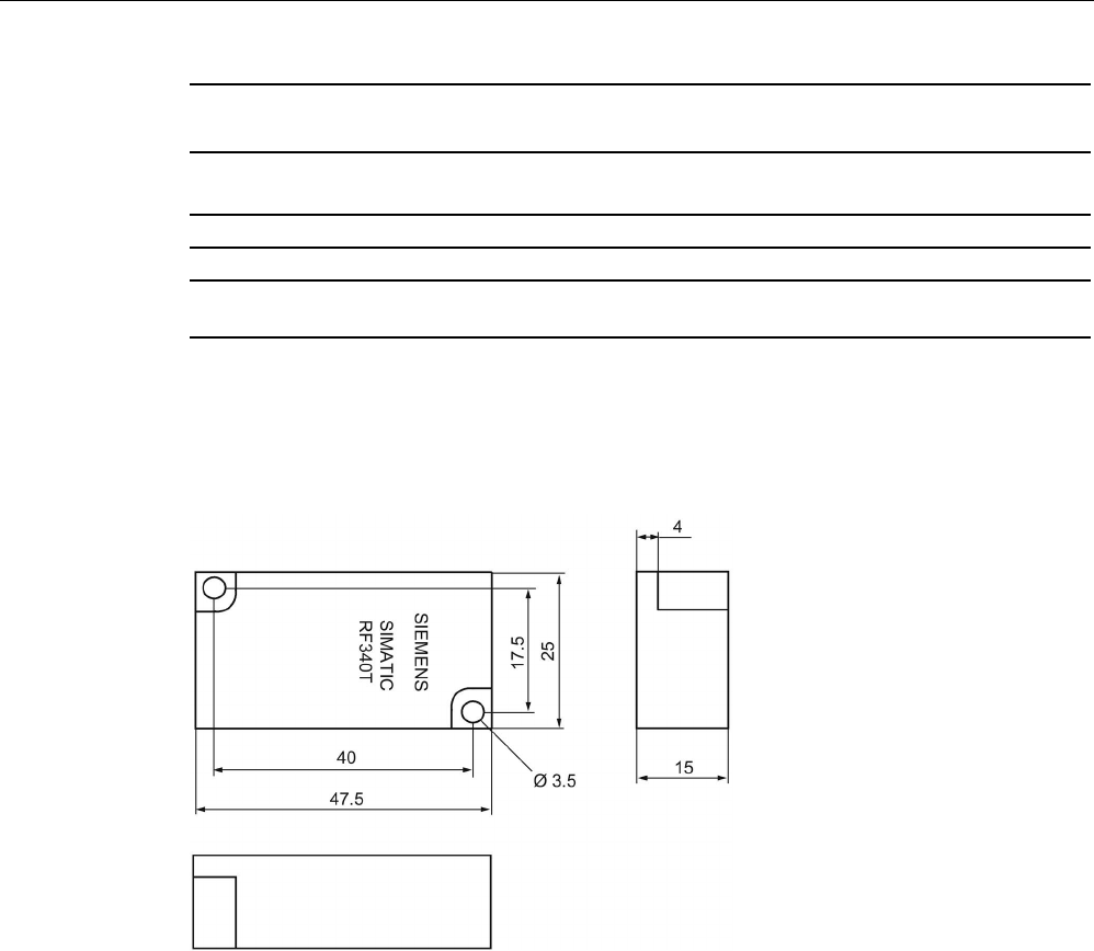
RF300 transponder
7.4 SIMATIC RF340T
SIMATIC RF300
System Manual, 07/2017, C79000-G8976-C345-07 247
6GT2800-4BB00
6GT2800-5BB00
Design, dimensions and weights
Dimensions (L x W x H)
48 x 25 x 15 mm
Weight
25 g
Type of mounting 2 x M3 screws
≤ 1.0 Nm
1) The values for shock and vibration are maximum values and must not be applied continuously.
7.4.5
Dimension drawing
Figure 7-11 RF340T dimension drawing
Dimensions in mm
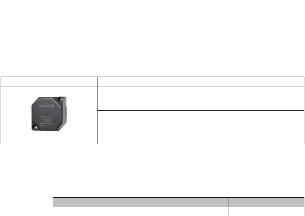
RF300 transponder
7.5 SIMATIC RF350T
SIMATIC RF300
248 System Manual, 07/2017, C79000-G8976-C345-07
7.5
SIMATIC RF350T
7.5.1
Features
RF350T
Characteristics
Area of application Identification tasks on small assembly lines
in harsh industrial environments
Memory size
32 KB FRAM user memory
Write/read range See section Field data of RF300 tran-
sponders (Page 52)
Mounting on metal
Yes
Degree of protection
IP68
7.5.2
Ordering data
Table 7- 11 Ordering data RF350T
Article number
RF350T
6GT2800-5BD00
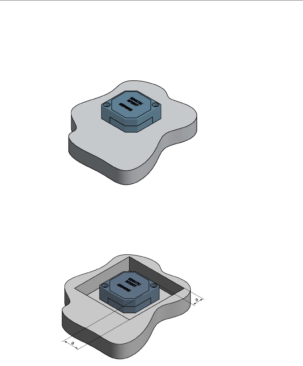
RF300 transponder
7.5 SIMATIC RF350T
SIMATIC RF300
System Manual, 07/2017, C79000-G8976-C345-07 249
7.5.3
Mounting on metal
Direct mounting of the RF350T on metal is permitted.
Mounting of RF350T on metal
Figure 7-12 Mounting of RF350T on metal
Flush-mounting of RF350T in metal:
Figure 7-13 RF350T flush-mounted in metal
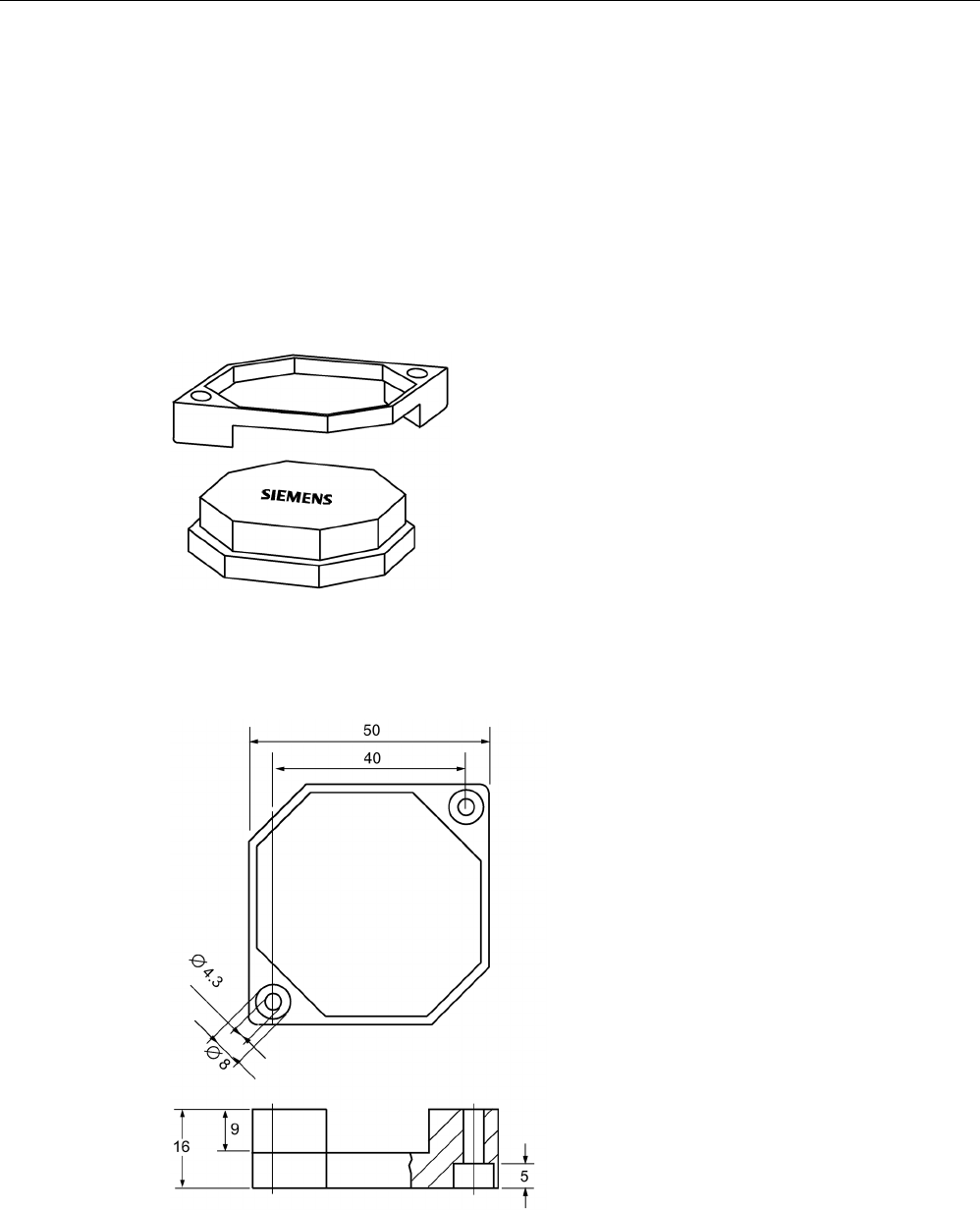
RF300 transponder
7.5 SIMATIC RF350T
SIMATIC RF300
250 System Manual, 07/2017, C79000-G8976-C345-07
The standard value for a is ≥ 20 mm. At lower values, the field data change significantly,
resulting in a reduction in the range.
7.5.4
Mounting options
Mounting with fixing frame
The RF350T transponder can be mounted as shown with the fixing frame:
Figure 7-14 Installation diagram
Dimensions of the fixing frame
Figure 7-15 RF350T fixing frame

RF300 transponder
7.5 SIMATIC RF350T
SIMATIC RF300
System Manual, 07/2017, C79000-G8976-C345-07 251
7.5.5
Technical data
Table 7- 12 Technical specifications for RF350T
6GT2800-5BD00
Product type designation
SIMATIC RF350T
Memory
Memory organization
in bytes
Memory configuration
• UID • 4 bytes EEPROM
• User memory • 32 KB FRAM
• OPT memory • 20 bytes EEPROM
Read cycles (at < 40 ℃)
> 10
10
Write cycles (at < 40 ℃)
> 10
10
Data retention time (at < 40 ℃)
> 10 years
Write/read distance (Sg) Dependent on the reader used, see section "Field
data of RF300 transponders (Page 52)"
MTBF (Mean Time Between Failures)
1200 years
Mechanical specifications
Enclosure
• Material • Plastic PA 12
• Color • Anthracite
Recommended distance to metal
≥ 0 mm
Power supply
Inductive, without battery
Permitted ambient conditions
Ambient temperature
• during write/read access • -25 to +85 ℃
• outside the read/write field • -40 to +85 ℃
• during storage • -40 to +85 ℃
Degree of protection to EN 60529
IP68
Shock-resistant acc. toEN 60721-3-7, Class 7
M3
1)
500 m/s2
Vibration-resistant to EN 60721-3-7, Class 7 M3
1)
200 m/s
2
Torsion and bending load
Not permitted
Design, dimensions and weights
Dimensions (L x W x H)
50 x 50 x 20 mm
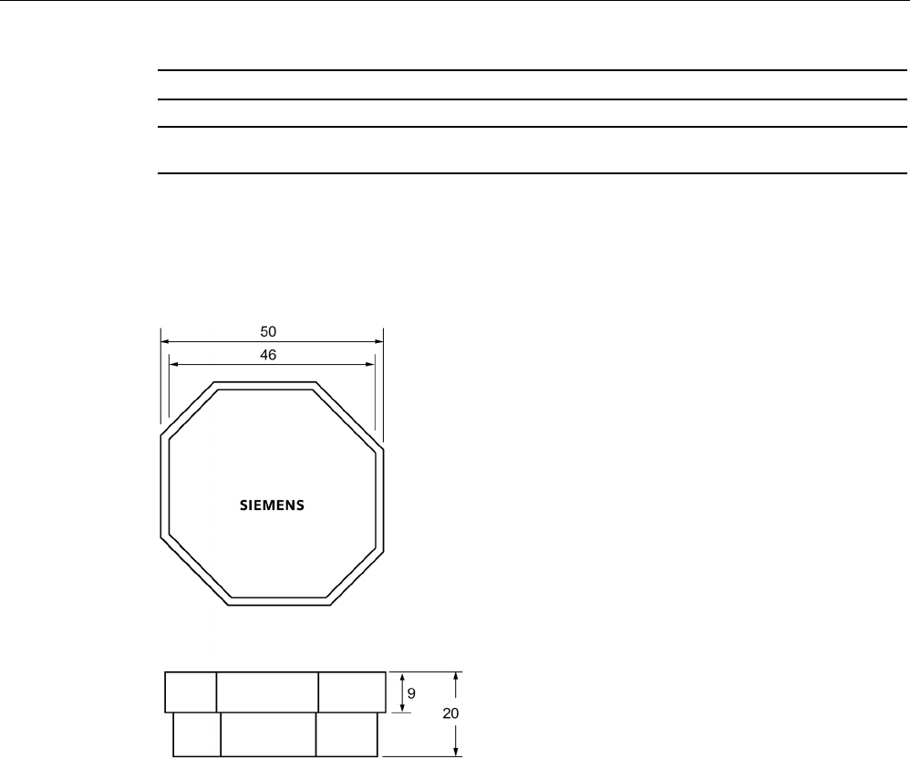
RF300 transponder
7.5 SIMATIC RF350T
SIMATIC RF300
252 System Manual, 07/2017, C79000-G8976-C345-07
6GT2800-5BD00
Weight
25 g
Type of mounting 2 x M4 screws
≤ 1.5 Nm
1) The values for shock and vibration are maximum values and must not be applied continuously.
7.5.6
Dimension drawing
Figure 7-16 RF350T dimension drawing
Dimensions in mm
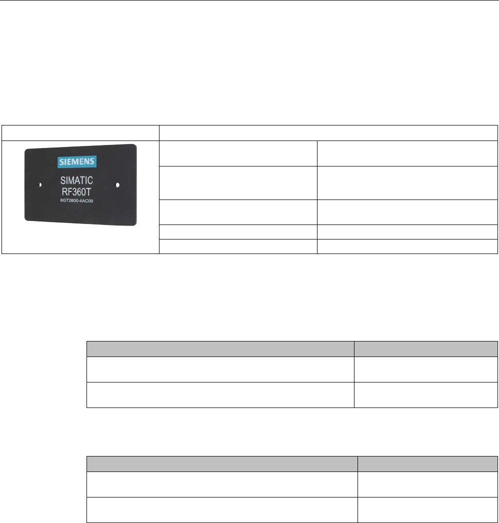
RF300 transponder
7.6 SIMATIC RF360T
SIMATIC RF300
System Manual, 07/2017, C79000-G8976-C345-07 253
7.6
SIMATIC RF360T
7.6.1
Features
RF360T
Characteristics
Area of application Identification tasks on small assembly lines
in harsh industrial environments
Memory size • 8 KB FRAM user memory
• 32 KB FRAM user memory
Write/read range see section Field data of RF300 tran-
sponders (Page 52)
Mounting on metal Yes, with spacer
Degree of protection
IP67
7.6.2
Ordering data
Table 7- 13 Ordering data RF360T
Article number
RF360T
8 KB FRAM user memory
6GT2800-4AC00
RF360T
32 KB FRAM user memory
6GT2800-5AC00
Table 7- 14 Ordering data for RF360T accessories
Article number
Spacer
(in conjunction with fixing pocket 6GT2190-0AB00)
6GT2190-0AA00
Fixing pocket
(in conjunction with spacer 6GT2190-0AA00)
6GT2190-0AB00
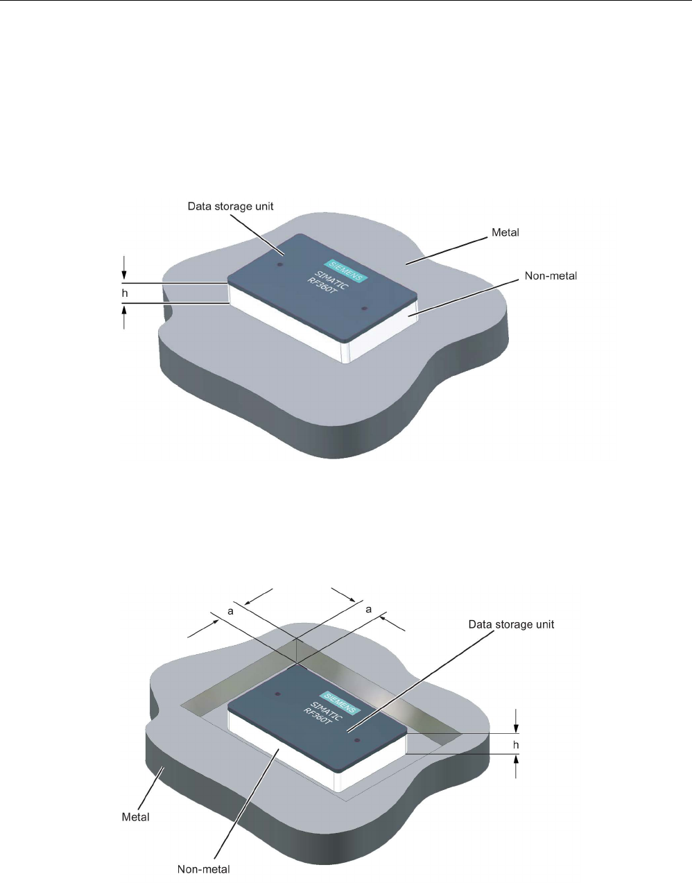
RF300 transponder
7.6 SIMATIC RF360T
SIMATIC RF300
254 System Manual, 07/2017, C79000-G8976-C345-07
7.6.3
Mounting on metal
Direct mounting of the RF360T on metal is not allowed. A distance ≥ 20 mm is
recommended. This can be achieved using the spacer 6GT2190-0AA00 in combination with
the fixing pocket 6GT2190-0AB00.
Mounting of RF360T on metal
Figure 7-17 Mounting of RF360T with spacer
The standard value for h is ≥ 20 mm.
Flush-mounting of RF360T in metal:
Figure 7-18 Flush-mounting of RF360T with spacer

RF300 transponder
7.6 SIMATIC RF360T
SIMATIC RF300
System Manual, 07/2017, C79000-G8976-C345-07 255
The standard value for a is ≥ 20 mm. At lower values, the field data change significantly,
resulting in a reduction in the range.

RF300 transponder
7.6 SIMATIC RF360T
SIMATIC RF300
256 System Manual, 07/2017, C79000-G8976-C345-07
Dimensions of spacer and fixing pocket for RF360T
Figure 7-19 Dimensions of spacer and fixing pocket for RF360T

RF300 transponder
7.6 SIMATIC RF360T
SIMATIC RF300
System Manual, 07/2017, C79000-G8976-C345-07 257
7.6.4
Technical data
Table 7- 15 Technical specifications for RF360T
6GT2800-4AC00
6GT2800-5AC00
Product type designation
SIMATIC RF360T
Memory
Memory organization
in bytes
Memory configuration
• UID • 4 bytes EEPROM
• User memory • 8 KB FRAM / 32 KB FRAM
• OPT memory • 20 bytes EEPROM
Read cycles (at < 40 ℃)
> 10
10
Write cycles (at < 40 ℃)
> 10
10
Data retention time (at < 40 ℃)
> 10 years
Write/read distance (Sg) Dependent on the reader used, see section "Field
data of RF300 transponders (Page 52)"
MTBF (Mean Time Between Failures)
1200 years
Mechanical specifications
Enclosure
• Material • Epoxy resin
• Color • Anthracite
Recommended distance to metal
≥ 20 mm
Power supply
Inductive, without battery
Permitted ambient conditions
Ambient temperature
• during write/read access • -25 to +75 ℃
• outside the read/write field • -40 to +85 ℃
• during storage • -40 to +85 ℃
Degree of protection to EN 60529
IP67
Shock-resistant to EN 60721-3-7, Class 7 M3 500 m/s2
Vibration-resistant to EN 60721-3-7, Class 7 M3 200 m/s2
Torsion and bending load Not permitted
Design, dimensions and weights
Dimensions (L x W x H) 86 x 55 x 2.5 mm
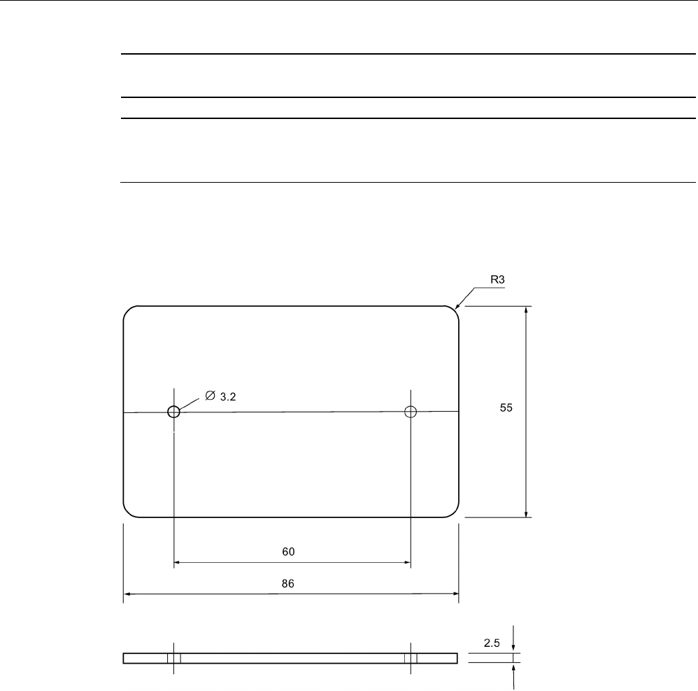
RF300 transponder
7.6 SIMATIC RF360T
SIMATIC RF300
258 System Manual, 07/2017, C79000-G8976-C345-07
6GT2800-4AC00
6GT2800-5AC00
Weight
25 g
Type of mounting • 2 x M3 screws
≤ 1.0 Nm
• Fixing pocket (6GT2190-0AB00)
7.6.5
Dimension drawing
Figure 7-20 RF360T dimension drawing
Dimensions in mm
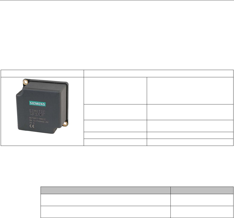
RF300 transponder
7.7 SIMATIC RF370T
SIMATIC RF300
System Manual, 07/2017, C79000-G8976-C345-07 259
7.7
SIMATIC RF370T
7.7.1
Features
The SIMATIC RF370T transponder is a passive (i.e. battery-free) data carrier in a square
type of construction.
RF370T
Characteristics
Area of application Identification tasks on assembly lines in
harsh industrial environments, due to high
resistance to oils, lubricants and cleaning
agents, and suitable for larger ranges, e.g.
automotive industry
Memory size • 32 KB FRAM user memory
• 64 KB FRAM user memory
Write/read range see section Field data of RF300 transpond-
ers (Page 52)
Mounting on metal
Yes
Degree of protection
IP68/IPx9K
7.7.2
Ordering data
Table 7- 16 Ordering data RF370T
Article number
RF370T
32 KB FRAM user memory
6GT2800-5BE00
RF370T
64 KB FRAM user memory
6GT2800-6BE00
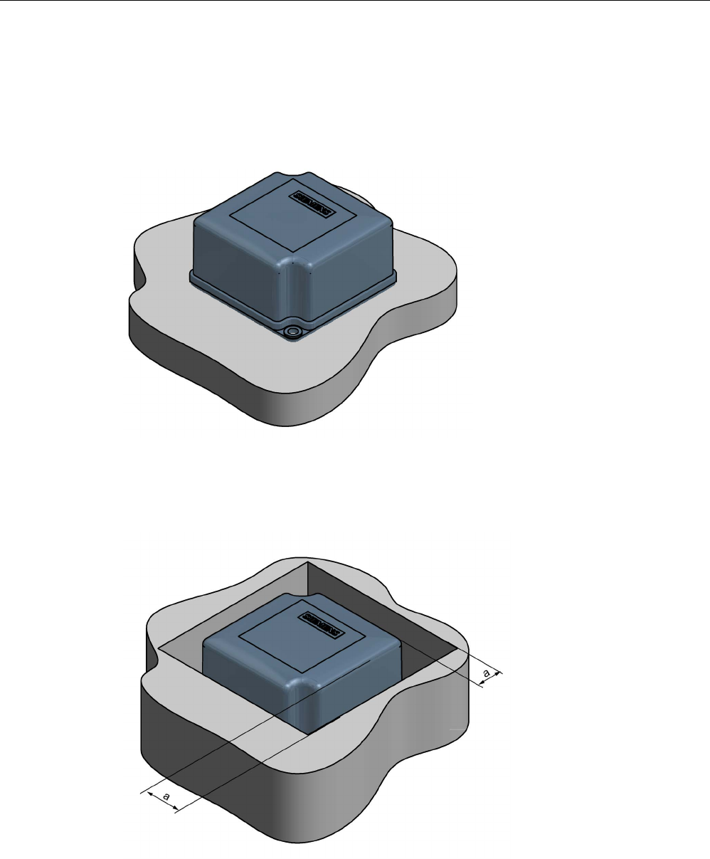
RF300 transponder
7.7 SIMATIC RF370T
SIMATIC RF300
260 System Manual, 07/2017, C79000-G8976-C345-07
7.7.3
Mounting on metal
Direct mounting of the RF370T on metal is permitted.
Mounting of RF370T on metal
Figure 7-21 Mounting of RF370T on metal
Flush-mounting of RF370T in metal:
Figure 7-22 RF370T flush-mounted in metal
The standard value for a is ≥ 20 mm. At lower values, the field data change significantly,
resulting in a reduction in the range.

RF300 transponder
7.7 SIMATIC RF370T
SIMATIC RF300
System Manual, 07/2017, C79000-G8976-C345-07 261
7.7.4
Mounting instructions
It is essential that you observe the instructions in the Section Installation guidelines
(Page 67).
Properties
Description
Type of installation
Screw fixing (two M5 screws)
Tightening torque < 1.2 Nm (at room temperature)
7.7.5
Technical specifications
Table 7- 17 Technical specifications RF370T
6GT2800-5BE00
6GT2800-6BE00
Product type designation
SIMATIC RF370T
Memory
Memory organization
in bytes
Memory configuration
• UID • 4 bytes EEPROM
• User memory • 32 KB FRAM / 64 KB FRAM
• OPT memory • 20 bytes EEPROM
Read cycles (at < 40 ℃)
> 10
10
Write cycles (at < 40 ℃)
> 10
10
Data retention time (at < 40 ℃)
> 10 years
Write/read distance (Sg) Dependent on the reader used, see section "Field
data of RF300 transponders (Page 52)"
MTBF (Mean Time Between Failures)
1200 years
Mechanical specifications
Enclosure
• Material • Plastic PA 12
• Color • Anthracite
Recommended distance to metal
≥ 0 mm
Power supply
Inductive, without battery
Permitted ambient conditions
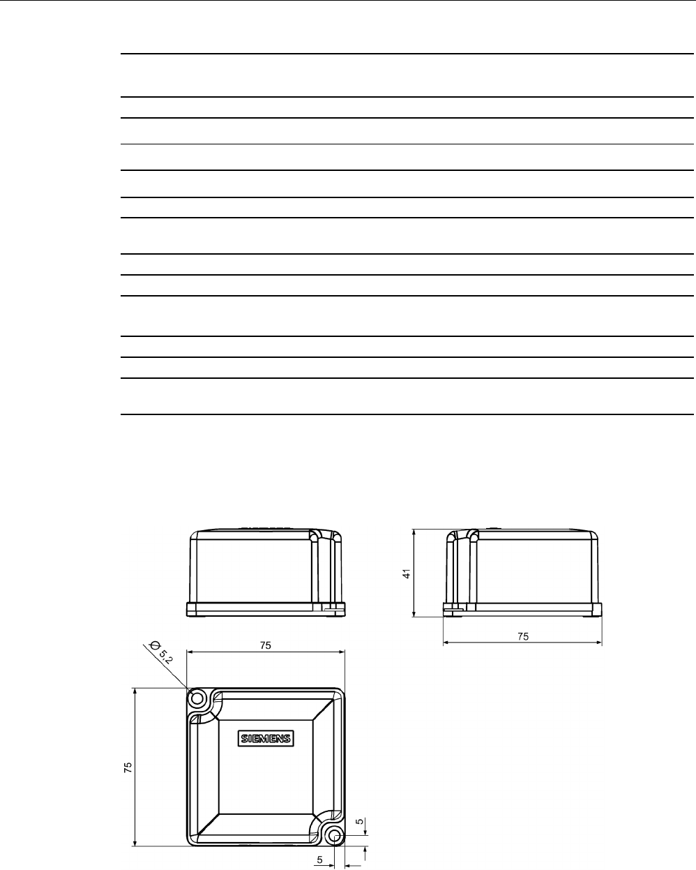
RF300 transponder
7.7 SIMATIC RF370T
SIMATIC RF300
262 System Manual, 07/2017, C79000-G8976-C345-07
6GT2800-5BE00
6GT2800-6BE00
Ambient temperature
• during write/read access • -25 to +85 ℃
• outside the read/write field • -40 to +85 ℃
• during storage • -40 to +85 ℃
Degree of protection to EN 60529
IPx9K
Shock-resistant acc. toEN 60721-3-7, Class 7
M3
1)
500 m/s2
Vibration-resistant to EN 60721-3-7, Class 7 M3
1)
200 m/s
2
Torsion and bending load
Not permitted
Design, dimensions and weights
Dimensions (L x W x H)
75 x 75 x 41 mm
Weight
200 g
Type of mounting 2 x M5 screws
≤ 1.5 Nm
1) The values for shock and vibration are maximum values and must not be applied continuously.
7.7.6
Dimensional drawing
Figure 7-23 RF370T dimension drawing
Dimensions in mm
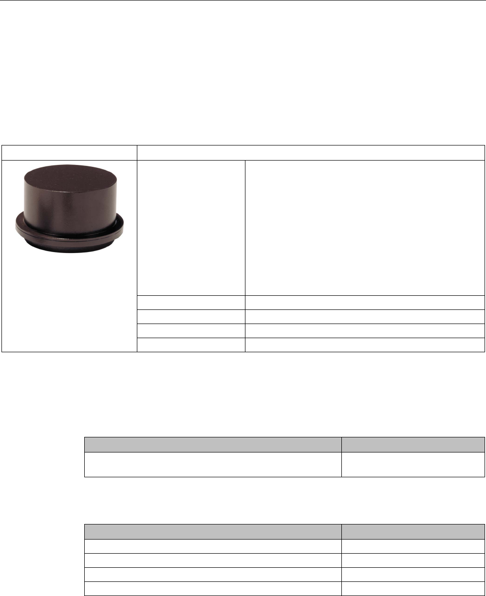
RF300 transponder
7.8 SIMATIC RF380T
SIMATIC RF300
System Manual, 07/2017, C79000-G8976-C345-07 263
7.8
SIMATIC RF380T
7.8.1
Features
The SIMATIC RF380T transponder is an extremely rugged and heat-resistant round data
carrier suitable e.g. for applications in the automotive industry.
SIMATIC RF380T transponder
Characteristics
Area of application Identification tasks in applications (e.g. automotive industry)
with cyclic high temperature stress > 85 °C and < 220 °C
Highly resistant to mineral oils, lubricants and cleaning
agents
Typical applications:
• Primer coat, electrolytic dip area, cataphoresis with the
associated drying furnaces
• Top coat area with drying furnaces
• Washing areas at temperatures > 85°C
• Other applications with higher temperatures
Memory size 32 KB FRAM user memory
Write/read range
see section "Field data of RF300 transponders (Page 52)"
Mounting on metal
Yes, flush-mounted in metal
Degree of protection
IP68
7.8.2
Ordering data
Table 7- 18 Ordering data RF380T
Article number
RF380T
User memory 32 KB FRAM (read/write) and 4 bytes EEPROM
6GT2800-5DA00
Table 7- 19 Ordering data for RF380T
Article number
Holder (short version)
6GT2090-0QA00
Holder (long version)
6GT2090-0QA00-0AX3
Shrouding cover
6GT2090-0QB00
Universal holder
6GT2590-0QA00
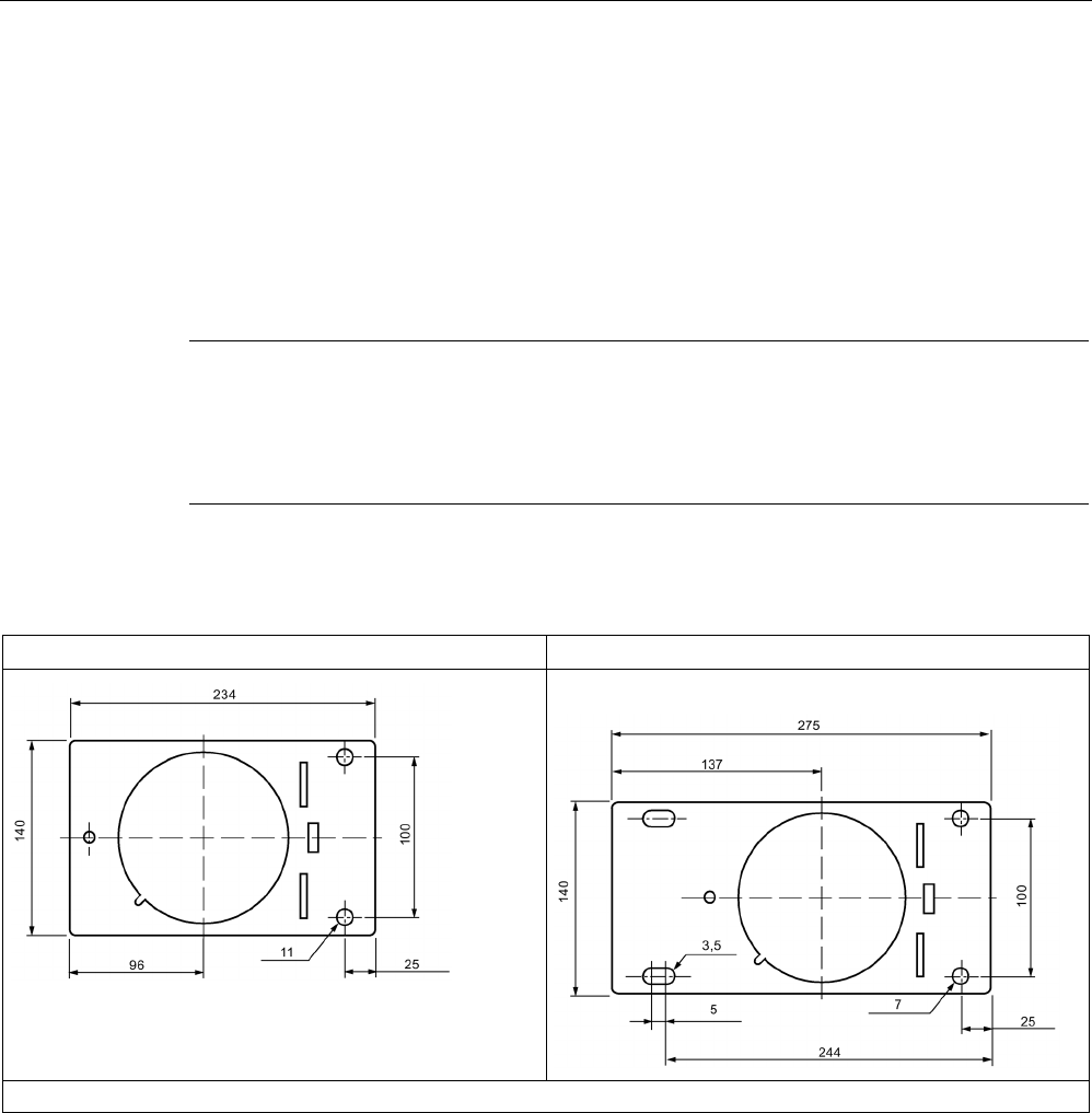
RF300 transponder
7.8 SIMATIC RF380T
SIMATIC RF300
264 System Manual, 07/2017, C79000-G8976-C345-07
7.8.3
Installation guidelines for RF380T
It is essential that you observe the instructions in the Section Installation guidelines
(Page 67)
.
The following section only deals with features specific to the SIMATIC RF380T.
7.8.3.1
Mounting instructions
Note
Only use tag with original holder
You are strongly recommended to only use the tag with the original holder specified. Only
th
is holder guarantees that the data memory observes the listed values for shock, vibration
and temperature. A protective cover is recommendable for applications in paint shops.
Data memory holder
Short version (6GT2 090-0QA00)
Long version (6GT2090-0QA00-0AX3)
Material: V2A sheet-steel with thickness 2.5 mm BI 2.5 DIN 59382 1.4541
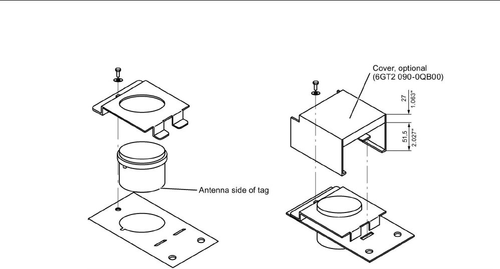
RF300 transponder
7.8 SIMATIC RF380T
SIMATIC RF300
System Manual, 07/2017, C79000-G8976-C345-07 265
Assembly of data memory with holder
Figure 7-24 Assembly of tag with holder
Scope of supply
The holder is provided with all mounting parts and a mounting diagram. Mounting screws for
securing the holder are not included. The mounting screws are of diameter M 10. The
minimum length is 25 mm. The optional cover can be used for the long and short versions of
the holder.
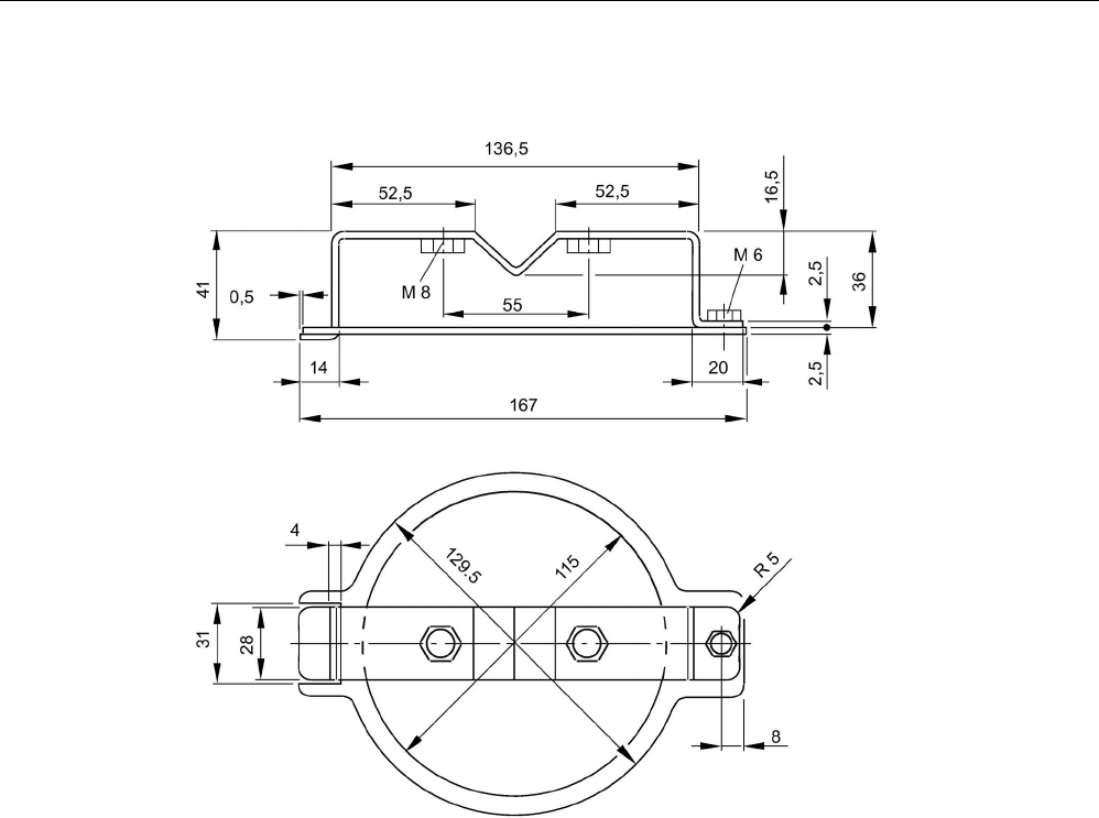
RF300 transponder
7.8 SIMATIC RF380T
SIMATIC RF300
266 System Manual, 07/2017, C79000-G8976-C345-07
Universal holder
Figure 7-25 Universal holder 6GT2590-0QA00
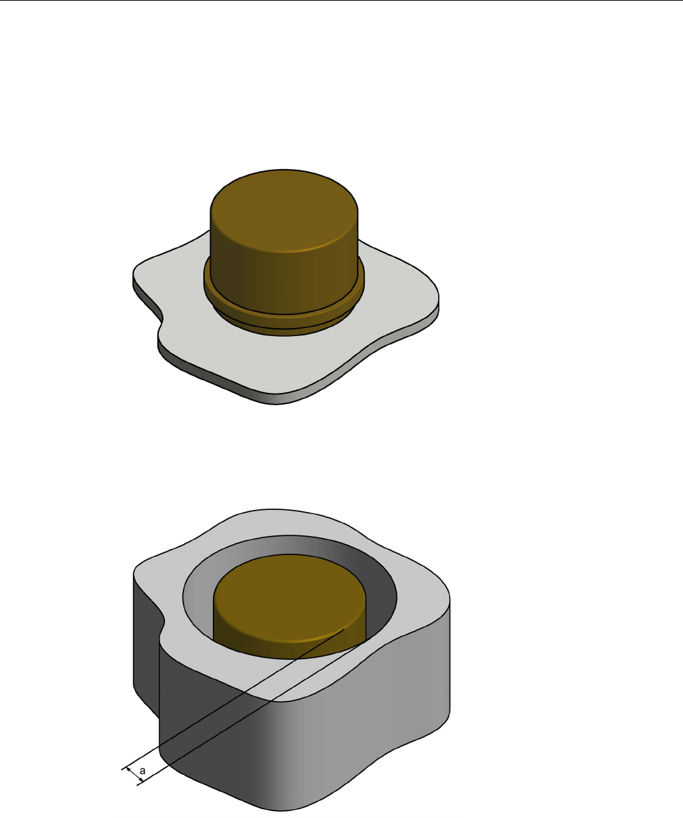
RF300 transponder
7.8 SIMATIC RF380T
SIMATIC RF300
System Manual, 07/2017, C79000-G8976-C345-07 267
7.8.3.2
Metal-free area
Direct mounting of the RF380T on metal is permitted.
Mounting of RF380T on metal
Figure 7-26 Mounting of RF380T on metal
Flush-mounting of RF380T in metal:
Figure 7-27 RF380T flush-mounted in metal
The standard value for a is ≥ 40 mm. At lower values, the field data change significantly,
resulting in a reduction in the range.

RF300 transponder
7.8 SIMATIC RF380T
SIMATIC RF300
268 System Manual, 07/2017, C79000-G8976-C345-07
7.8.4
Configuring instructions
7.8.4.1
Temperature dependence of the transmission window
The guidelines in the section "Planning the RF300 system" apply to configuration of heat-
resistant data memories, with the exception of the limit distance and field length at
temperatures above 85 °C. At temperatures above 85 °C, the length of the transmission
window is reduced by up to 10%.
7.8.4.2
Temperature response in cyclic operation
At ambient temperatures (Tu) up to 110 °C, cyclic operation is not necessary, i.e. up to this
temperature, the transponder can be in constant operation.
Note
Calculation of the temperature curves
Calculation of the temperature curves or of a temperature prof
ile can be carried out on
request by Siemens AG. Exact knowledge of the internal temperature facilitates
configuration for time
-critical applications.
You can also carry out the calculation with the aid of the "SIMATIC RF Temperature
Calculator" on the "Id
ent Systems Software & Documentation" DVD (refer to the section
"
DVD "Ident Systems Software & Documentation" (Page 435)").
Ambient temperatures > 110 °C
Note
Cancellation of warranty
The internal temperature of the data memory must not exceed the critical threshold of 110
°C. Each heating phase must be followed by a cooling phase. No warranty claims will
otherwise be accepted.
Some limit cycles are listed in the table below:
Table 7- 20 Limit cycles of data memory temperature
Tu (heating up)
Heating up
Tu (cooling down)
Cooling down
220 °C
0.5 h
25 °C
> 2 h
200 °C
1 h
25 °C
> 2 h
190 °C
1 h
25 °C
> 1 h 45 min
180 °C
2 h
25 °C
> 5 h
170 °C 2 h 25 °C > 4 h

RF300 transponder
7.8 SIMATIC RF380T
SIMATIC RF300
System Manual, 07/2017, C79000-G8976-C345-07 269
The internal temperature of the tag follows an exponential function with which the internal
temperature and the operability of the tag can be calculated in advance. This is particularly
relevant to temperature-critical applications or those with a complex temperature profile.
Ambient temperatures > 220°C
Note
Cancellation of warranty
The data memory must not be exposed to ambient temperatures > 220 °C. No warranty
claims will otherwise be accepte
d.
However, the mechanical stability is retained up to 230 °C!
Example of a cyclic sequence
Table 7- 21 Typical temperature profile of an application in the paint shop
Start of tag at initial point
Duration (min)
Ambient temperature (°C)
Electrolytic dip
20
30
Electrolytic dip dryer
60
200
Transport
60
25
PVC dryer
25
170
Transport
60
25
Filler dryer
60
160
Transport
60
25
Top coat dryer
60
120
Transport
60
25
Wax dryer
25
100
Transport
150
25
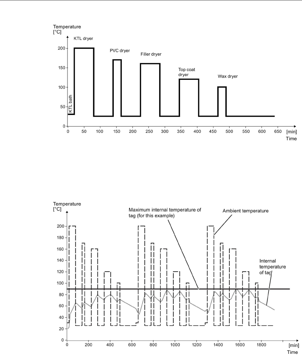
RF300 transponder
7.8 SIMATIC RF380T
SIMATIC RF300
270 System Manual, 07/2017, C79000-G8976-C345-07
Figure 7-28 Graphic trend of temperature profile from above table
The simulation results in the following:
Following a simulation time of 36.5 hours, a total of 3 cycles were carried out, and an internal
temperature of 90 degrees Celsius was reached.
Figure 7-29 Complete temperature response due to simulation
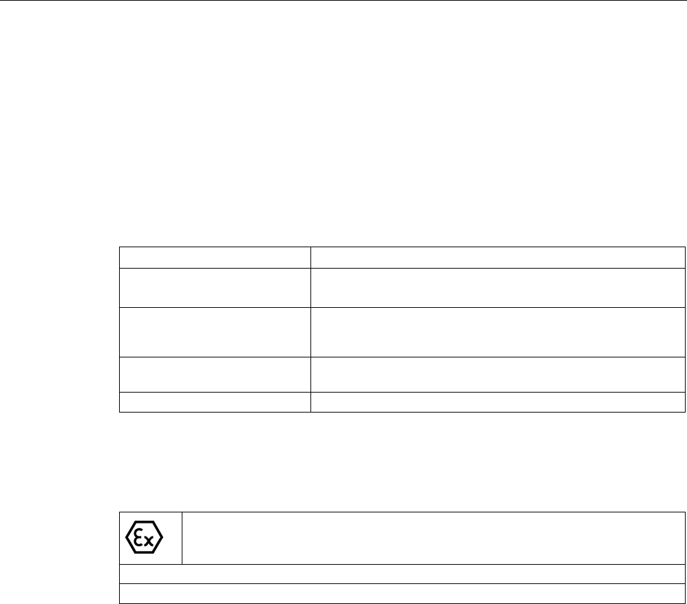
RF300 transponder
7.8 SIMATIC RF380T
SIMATIC RF300
System Manual, 07/2017, C79000-G8976-C345-07 271
7.8.5
Use of the transponder in the Ex protection area
The TÜV SÜD Automotive GmbH as approved test center as well as the TÜV SÜD Product
Service GmbH as certification center, identification number 0123, as per Article 9 of the
Directive of the European Council of 23 March 1994 (94/9/EC), has confirmed the
compliance with the essential health and safety requirements relating to the design and
construction of equipment and protective systems intended for use in hazardous areas as
per Annex II of the Directive. The essential health and safety requirements are satisfied in
accordance with the following standards:
Table 7- 22 Approvals
Document
Title
EN 60079-0: 2006
Electrical equipment for hazardous gas atmospheres -
Part 0: General requirements
EN 60079-15: 2005 Electrical equipment for hazardous gas atmospheres -
Part 15: Design, testing and identification of electrical equipment
with type of protection "n"
DIN VDE 0848-5: 2001
(in parts)
Safety in electrical, magnetic and electromagnetic fields -
Part 5: Explosion protection
ZLS SK 107.1
Central office of the states for safety; test components
Identification
Table 7- 23 The identification of the electrical equipment as an encapsulated unit
II 3G Ex nC IIB T5
-25°C to +70°C
Um=30Vdc
The equipment is assigned the following references:
XXXYYYZZZ
[= serial number, is assigned during production]
TPS 09 ATEX 1 459 X
[= certificate number]
"No use of the equipment in the vicinity of processes generating high charges"
RF300 transponder
7.8 SIMATIC RF380T
SIMATIC RF300
272 System Manual, 07/2017, C79000-G8976-C345-07
7.8.5.1
Use of the transponder in hazardous areas for gases
Temperature class delineation for gases
The temperature class of the transponder for hazardous areas depends on the ambient
temperature range:
Ambient temperature range
Temperature class
-25 °C to +70 °C
T5
WARNING
Ignitions of gas-air mixtures
• When using the RF380T transponder, check that the temperature class is kept to in
conjunction with the requirements of the area of application.
If the temperature ranges are exceeded during use of the transponder, gas-air mixtures
may be ignited.
• The maximum transmit power of the transmitter used to operate the transponder must
not exceed 2 W.
If the transmit power id not kept to, gas-air mixtures may ignite.
7.8.5.2
Installation and operating conditions for the hazardous area
a) Use of the equipment in the vicinity of processes generating high charges is not allowed.
b) The equipment must be mechanically protected when installed.
7.8.6
Cleaning the mobile data memory
Note
Do not clean the transponder with mechanical tools, sand
-blasting or pressure hose. These
cleaning methods result in damage to the transponder.
Clean th
e transponder only with the chemical cleansing agents listed in Chapter Chemical
resistance of the readers and transponders
(Page 97).

RF300 transponder
7.8 SIMATIC RF380T
SIMATIC RF300
System Manual, 07/2017, C79000-G8976-C345-07 273
7.8.7
Technical specifications
Table 7- 24 RF380T technical specifications
6GT2800-5DA00
Product type designation
SIMATIC RF380T
Memory
Memory organization
in bytes
Memory configuration
• UID • 4 bytes EEPROM
• User memory • 32 KB FRAM
• OPT memory • 20 bytes EEPROM
Read cycles (at < 40 ℃)
> 10
10
Write cycles (at < 40 ℃)
> 10
10
Data retention time (at < 40 ℃)
> 10 years
Write/read distance (Sg) Dependent on the reader used, see section "Field
data of RF300 transponders (Page 52)"
MTBF (Mean Time Between Failures)
1177 years
Mechanical specifications
Enclosure
• Material • PPS
• Color • Anthracite
Recommended distance to metal
≥ 0 mm
Power supply
Inductive, without battery
Permitted ambient conditions
Ambient temperature
• during write/read access • -25 … +110 °C
> 110 °C °C: cyclic operation possible
• outside the read/write field • -40 ... +220 °C
• during storage • -40 to +110 ℃
Degree of protection to EN 60529
IP68
Shock-resistant acc. to EN 60721-3-7, Class 7
M3
1)2)
500 m/s2
Vibration-resistant to EN 60721-3-7, Class 7 M3
2)
50 m/s
2
Torsion and bending load
Not permitted
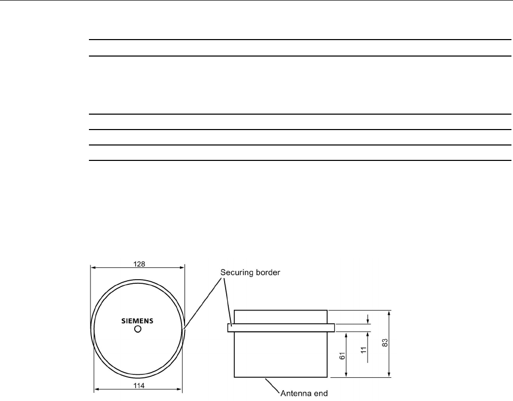
RF300 transponder
7.8 SIMATIC RF380T
SIMATIC RF300
274 System Manual, 07/2017, C79000-G8976-C345-07
6GT2800-5DA00
Design, dimensions and weights
Dimensions (Ø x H)
114 x 83 mm
Weight
900 g
Type of mounting
Holder (must be ordered separately)
1)
Applies only in conjunction with the original support
2) The values for shock and vibration are maximum values and must not be applied continuously.
7.8.8
Dimensional drawing
Figure 7-30 Dimension drawing RF380T
Dimensions in mm
SIMATIC RF300
System Manual, 07/2017, C79000-G8976-C345-07 275
ISO transponder
8
Features of the ISO transponders
The transponders (MDS D) that are compatible with ISO 15693 represent a cost-effective
alternative to RF300 transponders. The performance that can be achieved with this
(transmission speed, memory size), however, is considerably less than with RF300
transponders.
You will find more information on transmission speeds in the section "Communication
between communications module, reader and transponder (Page 50)".
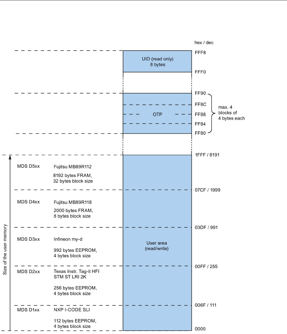
ISO transponder
8.1 Memory configuration of ISO the transponders
SIMATIC RF300
276 System Manual, 07/2017, C79000-G8976-C345-07
8.1
Memory configuration of ISO the transponders
Figure 8-1 Memory configuration of ISO the transponders

ISO transponder
8.1 Memory configuration of ISO the transponders
SIMATIC RF300
System Manual, 07/2017, C79000-G8976-C345-07 277
Memory areas
Depending on the manufacturer of the transponder chip, the memory configuration of an ISO
transponder consists of varying sizes of user memory.
The typical sizes are 112 bytes, 256 bytes, 992 bytes EEPROM or 2000 bytes FRAM. Each
ISO transponder chip has an 8-byte long unique serial number (UID, read only). This UID is
transferred as an 8 byte value through a read command to address FFF0 with a length of 8.
OTP area
For the OTP area, a 16-byte address space is always reserved at the end of the memory
area. The blocks are divided up depending on the chip (see technical specifications). Note
that the corresponding addresses for the user data are therefore not available to the
application when the OTP area is used.
A total of 4 block addresses ("mapped" addresses) are provided:
● FF80
● FF84
● FF88
● FF8C
A write command to this block address with a valid length (4, 8, 12, 16 bytes depending on
the block address) protects the written data from subsequent overwriting.
Note
Exception Fujitsu chip (MDS D4xx and MDS D5xx)
The Fujitsu chip MB89R118 (MDS D4xx) has 8
-byte blocks, which means that only 2 block
addresses have to be addressed: FF80 and FF88 with the length 8 and 16 bytes).
The Fujitsu chip MB89R112 (MDS D5xx) has 32 byte blocks
and can therefore not be
addressed in the OTP area.
Note
Restriction to the use of the OTP
Observe the following restrictions when using OTP:
•
The OTP write/lock command can only be sent in static operation.
•
The OTP write/lock command can not be sent as a chained command.
The Fujitsu chip MB89R112 (MDS D5xx) has 32 byte blocks and can therefore not be
addressed in the OTP area.
Note
Use of the OTP area is not reversible
If you use the OPT area, you cannot undo it, because the OPT area can only be wri
tten to
once.
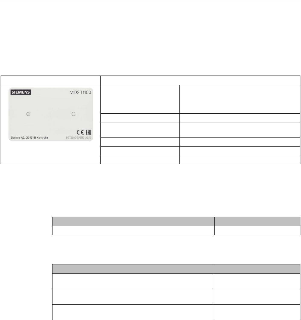
ISO transponder
8.2 MDS D100
SIMATIC RF300
278 System Manual, 07/2017, C79000-G8976-C345-07
8.2
MDS D100
8.2.1
Characteristics
MDS D100
Characteristics
Area of application From simple identification such as electronic
barcode replacement/supplementation, through
warehouse and distribution logistics, right up to
product identification.
Memory size
112 bytes of EEPROM user memory
Write/read range See section Field data of ISO transponders
(MDS D) (Page 56).
Mounting on metal
Yes, with spacer
ISO standard
ISO 15693
Degree of protection
IP68
8.2.2
Ordering data
Table 8- 1 Ordering data for MDS D100
Article number
MDS D100
6GT2600-0AD10
Table 8- 2 Ordering data for MDS D100 accessory
Article number
Spacer
(in conjunction with fixing pocket 6GT2190-0AB00)
6GT2190-0AA00
Fixing pocket
(in conjunction with spacer 6GT2190-0AA00)
6GT2190-0AB00
Fixing pocket
(not suitable for fixing directly onto metal)
6GT2390-0AA00
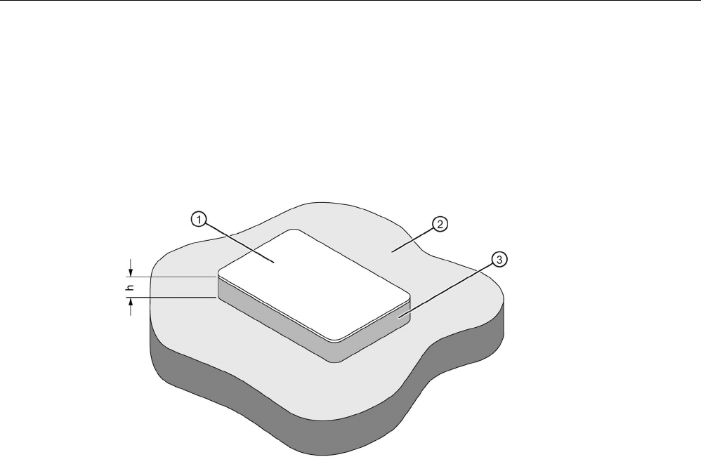
ISO transponder
8.2 MDS D100
SIMATIC RF300
System Manual, 07/2017, C79000-G8976-C345-07 279
8.2.3
Metal-free area
Direct mounting of the MDS D100 on metal is not allowed. A distance of ≥ 20 mm is
recommended. This can be achieved using the spacer 6GT2190-0AA00 in combination with
the fixing pocket 6GT2190-0AB00.
Mounting on metal
h
≥ 20 mm
①
Transponder
②
Metal
③
Non-metal
Figure 8-2 Mounting of the MDS D100 on metal with spacer
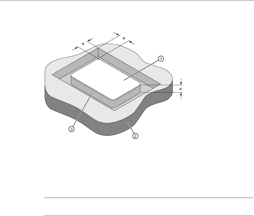
ISO transponder
8.2 MDS D100
SIMATIC RF300
280 System Manual, 07/2017, C79000-G8976-C345-07
Flush-mounting
a
≥ 20 mm
h
≥ 20 mm
①
Transponder
②
Metal
③
Non-metal
Figure 8-3 Flush-mounting of MDS D100 in metal with spacer
Note
If the minimum guide values (h or
a) are not observed, a reduction of the field data results.

ISO transponder
8.2 MDS D100
SIMATIC RF300
System Manual, 07/2017, C79000-G8976-C345-07 281
8.2.4
Technical data
Table 8- 3 Technical specifications for MDS D100
6GT2600-0AD10
Product type designation
SIMATIC MDS D100
Memory
Memory configuration
• UID • 8 bytes
• User memory • 112 bytes EEPROM
• OTP memory • 16 bytes (EEPROM)
Read cycles (at < 40 ℃)
> 10
14
Write cycles (at < 40 ℃)
> 10
6
Data retention time (at < 40 ℃)
> 10 years
Write/read distance (Sg) Dependent on the reader used, see section "Field
data of ISO transponders (MDS D) (Page 56)"
MTBF (Mean Time Between Failures)
228 years
Mechanical specifications
Housing
• Material • PET
• Color • White/black
Recommended distance to metal
≥ 20 mm
Power supply
Inductive, without battery
Permitted ambient conditions
Ambient temperature
• during write/read access • -25 to +80 ℃
• outside the read/write field • -25 to +80 ℃
• during storage • -25 to +80 ℃
Degree of protection to EN 60529
IP68
Shock-resistant to EN 60721-3-7 class 7M3
ISO 10373 / ISO 7810
1)
Vibration-resistant to EN 60721-3-7, class 7M3 ISO 10373 / ISO 7810 1)
Torsion and bending load ISO 10373/ISO 7816-1
Design, dimensions and weight
Dimensions (L x W x H) 85.6 x 54 x 0.9 mm
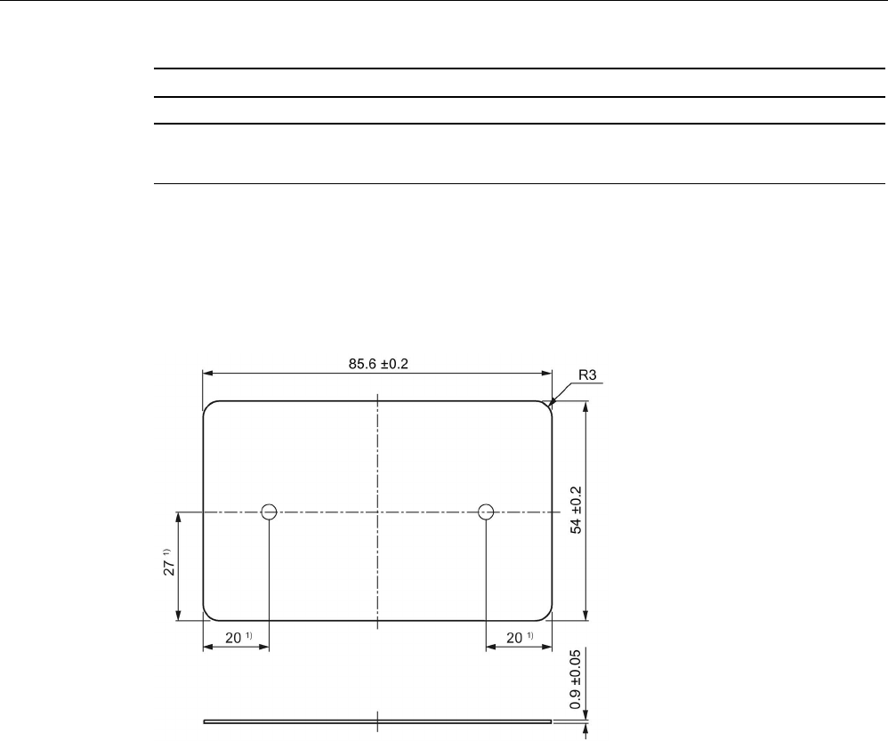
ISO transponder
8.2 MDS D100
SIMATIC RF300
282 System Manual, 07/2017, C79000-G8976-C345-07
6GT2600-0AD10
Weight
5 g
Type of mounting • Fixing pocket
• Glued 2)
1)
The values for shock and vibration are maximum values and must not be applied continuously.
2) The processing instructions of the adhesive manufacturer must be observed.
8.2.5
Dimension drawing
Dimensions in mm
1)
Dimensions for mounting holes
Figure 8-4 MDS D100 dimension drawing
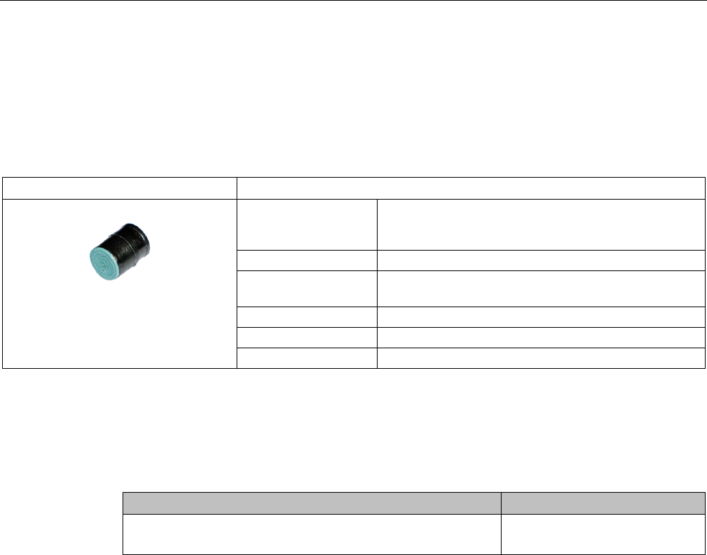
ISO transponder
8.3 MDS D117
SIMATIC RF300
System Manual, 07/2017, C79000-G8976-C345-07 283
8.3
MDS D117
8.3.1
Features
MDS D117
Characteristics
Area of application Very compact data carrier that can be cemented into
objects where precise positioning is necessary;
e.g. tool identification, workpiece holders etc..
Memory size 112 bytes of EEPROM user memory
Write/read range See section "Field data of ISO transponders (MDS D)
(Page 56)."
Mounting in metal
Yes, flush-mounted in metal
ISO standard
ISO 15693
Degree of protection
IP68/IPx9K
8.3.2
Ordering data
Table 8- 4 Ordering data for MDS D117
Article number
MDS D117
Pack of 10
6GT2600-0AG00
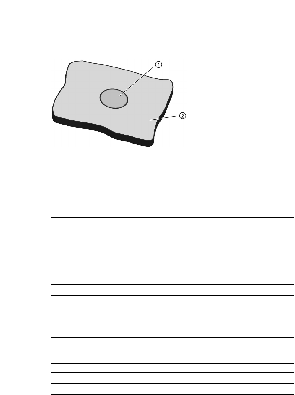
ISO transponder
8.3 MDS D117
SIMATIC RF300
284 System Manual, 07/2017, C79000-G8976-C345-07
8.3.3
Mounting in metal
Flush-mounted in metal
①
Transponder
②
Metal
8.3.4
Technical specifications
Table 8- 5 Technical specifications for MDS D117
6GT2600-0AG00
Product type designation
SIMATIC MDS D117
Memory
Memory configuration
• UID • 8 bytes
• User memory • 112 bytes EEPROM
• OTP memory • 16 bytes (EEPROM)
Read cycles (at < 40 ℃)
> 10
14
Write cycles (at < 40 ℃)
> 10
6
Data retention time (at < 40 ℃)
> 10 years
Write/read distance (Sg) Dependent on the reader used, see section "Field
data of ISO transponders (MDS D) (Page 56)"
MTBF (Mean Time Between Failures)
228 years
Mechanical specifications
Housing
• Material • PPS
• Color • Black
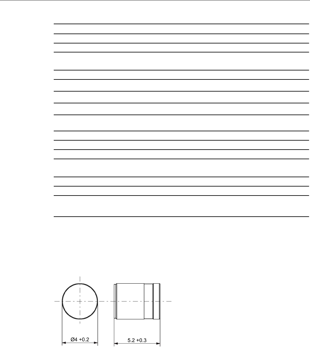
ISO transponder
8.3 MDS D117
SIMATIC RF300
System Manual, 07/2017, C79000-G8976-C345-07 285
6GT2600-0AG00
Recommended distance to metal
≥ 0 mm
Power supply
Inductive, without battery
Permitted ambient conditions
Ambient temperature
• during write/read access • -25 to +85 ℃
• outside the read/write field • -40 to +125 ℃
• during storage • -40 to +125 ℃
Degree of protection to EN 60529 IP68
2 hours, 2 bar, +20 °C
Shock according to EN 60721-3-7 Class 7M3
1)
1000 m/s
2
Vibration according to EN 60721-3-7 Class 7M3
1)
200 m/s
2
Torsion and bending load
Not permitted
Design, dimensions and weight
Dimensions (Ø x H)
4 x 5.2 mm
Weight
1 g
Type of mounting • Fixing pocket
• Glued 2)
1)
The values for shock and vibration are maximum values and must not be applied continuously.
2) The processing instructions of the adhesive manufacturer must be observed.
8.3.5
Dimension drawing
Figure 8-5 Dimensions in mm
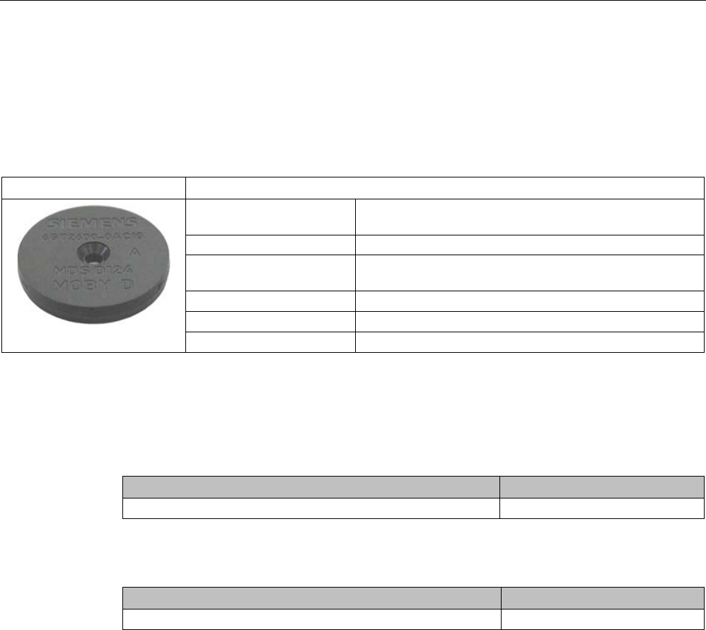
ISO transponder
8.4 MDS D124
SIMATIC RF300
286 System Manual, 07/2017, C79000-G8976-C345-07
8.4
MDS D124
8.4.1
Characteristics
MDS D124
Characteristics
Area of application Application areas in production automation (e.g. small
paintshops up to +180 °C)
Memory size
112 bytes of EEPROM user memory
Write/read range See section "Field data of ISO transponders (MDS D)
(Page 56)".
Mounting on metal
Yes, with spacer
ISO standard
ISO 15693
Degree of protection
IP68/IPx9K
8.4.2
Ordering data
Table 8- 6 Ordering data for MDS D124
Article number
MDS D124
6GT2600-0AC10
Table 8- 7 Ordering data for MDS D124 accessories
Article number
Spacer
6GT2690-0AK00

ISO transponder
8.4 MDS D124
SIMATIC RF300
System Manual, 07/2017, C79000-G8976-C345-07 287
8.4.3
Mounting on metal
Mounting on metal
h
≥ 15 mm
Figure 8-6 Mounting the MDS D124/D324/D424/D524/E624 and RF320T on metal with spacer
Flush-mounting
h
≥ 15 mm
a
≥ 25 mm
Figure 8-7 Flush-mounting of the MDS D124/D324/D424/D524/E624 and RF320T in metal with
spacer

ISO transponder
8.4 MDS D124
SIMATIC RF300
288 System Manual, 07/2017, C79000-G8976-C345-07
Note
Going below the distances
If the distances (a and h) are not observed, a reduction of the field data results. It is possible
to mount the MDS with metal screws (M3 countersunk head screws). T
his has no tangible
impact on the range.
8.4.4
Technical specifications
Table 8- 8 Technical specifications for MDS D124
6GT2600-0AC10
Product type designation
SIMATIC MDS D124
Memory
Memory configuration
• UID • 8 bytes
• User memory • 112 bytes EEPROM
• OTP memory • 16 bytes (EEPROM)
Read cycles (at < 40 ℃)
> 10
14
Write cycles (at < 40 ℃)
> 10
6
Data retention time (at < 40 ℃)
> 10 years
Write/read distance (Sg) Dependent on the reader used, see section "Field
data of ISO transponders (MDS D) (Page 56)"
MTBF (Mean Time Between Failures)
228 years
Mechanical specifications
Housing
• Material • PPS
• Color • Black
Recommended distance to metal
≥ 15 mm
Power supply
Inductive, without battery
Permitted ambient conditions
Ambient temperature
• during write/read access • -25 … +140 °C
• from +125 ℃: 20% reduction in the limit dis-
tance
• outside the read/write field • -40 to +180 ℃

ISO transponder
8.4 MDS D124
SIMATIC RF300
System Manual, 07/2017, C79000-G8976-C345-07 289
6GT2600-0AC10
• at +180 ℃: Tested up to 5000 hours or
3000 cycles
• during storage • -40 to +125 ℃
Degree of protection to EN 60529 • IP68
2 hours, 2 bar, +20 °C
• IPx9K
steam jet: 150 mm; 10 to 15 l/min; 100 bar; 75
°C
Shock according to EN 60721-3-7 Class 7M3
1)
1000 m/s
2
Vibration according to EN 60721-3-7 Class 7M3
1)
200 m/s
2
Torsion and bending load
Not permitted
Design, dimensions and weight
Dimensions (Ø x H)
4 x 5.2 mm
Weight
5 g
Type of mounting • 1 x M3 screw 2)
≤ 1 Nm
• Glued 3)
• With spacer
1)
The values for shock and vibration are maximum values and must not be applied continuously.
2
) To prevent it loosening during operation, secure the screw with screw locking varnish.
3) The processing instructions of the adhesive manufacturer must be observed.
8.4.5
Use of the MDS D124 in hazardous area
The mobile data memory MDS D124, device group II, category 1G or 1D may be installed
and operated in zones 0, 1 and 2 or in the zones 20, 21 and 22.
The following requirements of the 94/9/EC directive are met:
● EN 60079-0:2009
● EN 60079-11:2007
● EN 61241-11:2006
● EN 60079-26:2007
When used in hazardous areas, the MDS D124 must not be operated with field strengths > 5
A / m to avoid impermissible heating. This is not the case with readers from the SIMATIC RF
range (MOBY D, RF200 and RF300).
ISO transponder
8.4 MDS D124
SIMATIC RF300
290 System Manual, 07/2017, C79000-G8976-C345-07
Identification
II 1 G Ex ia IIC T3 to T6 Ga
or
II 1 D Ex ia IIIC T80 °C to T180 °C Da
TÜV 12 ATEX 084413 X
The temperature class or the maximum surface temperature depends on the maximum
ambient temperature. The relationship between temperature class (gas) or maximum surface
temperature (dust) can be found in the following table.
Table 8- 9 Ambient temperature
Ambient temperature range
Temperature class
Max. surface temperature
-25 ... +150 ℃
T3
T180
-25 ... +100 ℃
T4
T130
-25 ... +65 ℃
T5
T95
-25 ... +50 ℃
T6
T80
Note
Safety markings for hazardous areas
Since there is not enough space on the MDS D124 for the safety mark, this is supplied as a
label with the device.
This must be affixed immediately next to the MDS D124 so that the label clearly relates to
the device.
WARNING
Gefahr durch elektrostatische Entladungen
Potential electrostatic charging hazard
Danger potentiel de charges électrostatiques
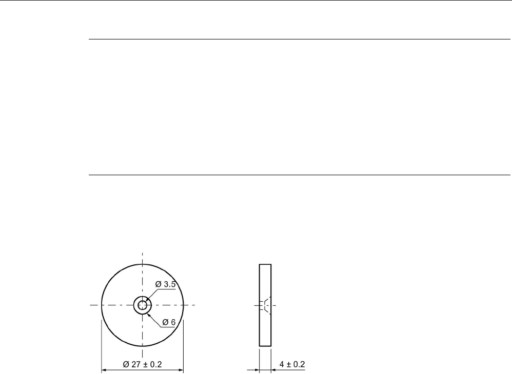
ISO transponder
8.4 MDS D124
SIMATIC RF300
System Manual, 07/2017, C79000-G8976-C345-07 291
Note
Installation and operating conditions for hazardous areas:
•
Use of the device in the vicinity of processes generating high charges is not allowed.
•
The device must be installed so that it is mechanically protected.
•
For applications requiring devices of category 1, the device must be mounted on a
grounded, conductive base.
•
It must only be cleaned with a damp cloth.
•
The device is suitable for use in atmospheres containing dust, however not for full
immersion in dust.
8.4.6
Dimension drawing
Figure 8-8 Dimension drawing of MDS D124
All dimensions in mm
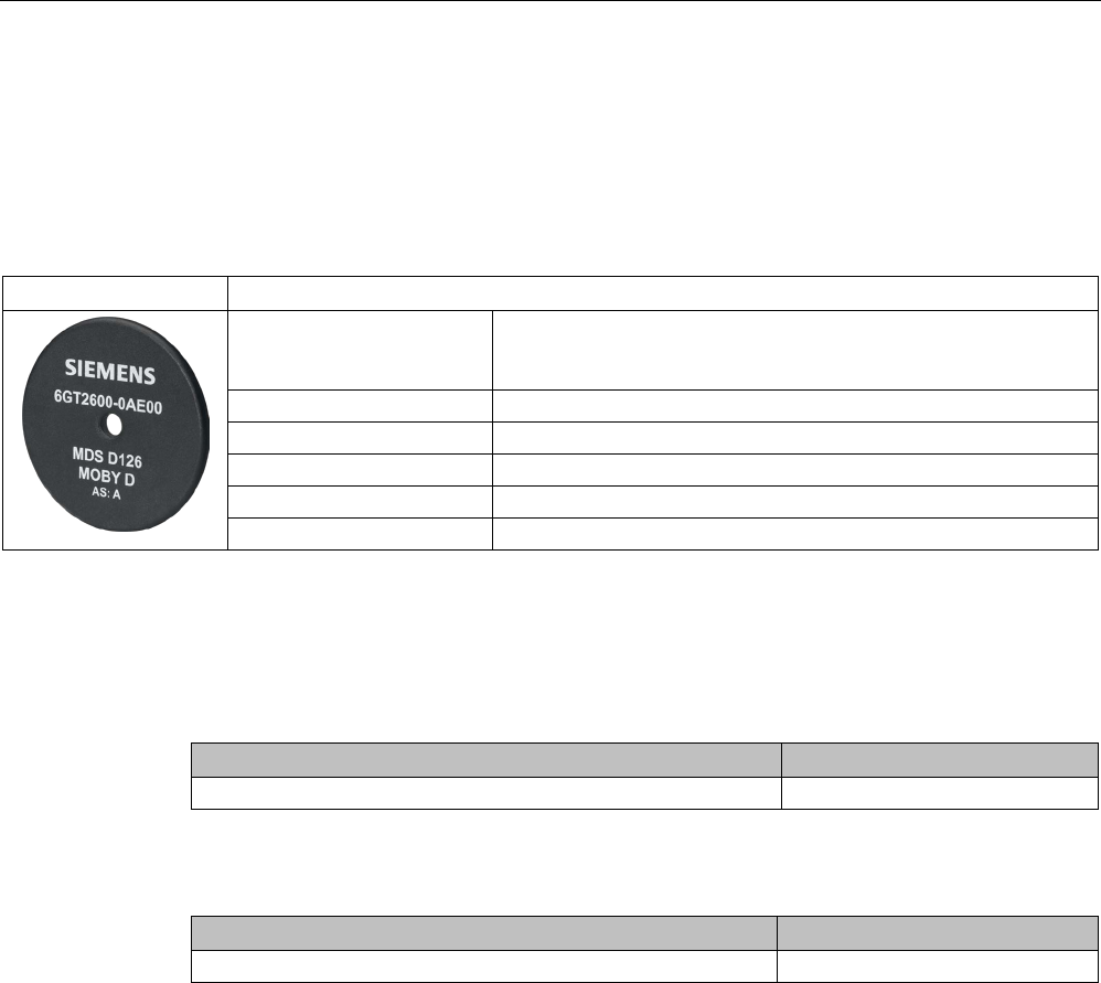
ISO transponder
8.5 MDS D126
SIMATIC RF300
292 System Manual, 07/2017, C79000-G8976-C345-07
8.5
MDS D126
8.5.1
Characteristics
MDS D126
Characteristics
Area of application Compact and rugged ISO transponder; suitable for identification of
transport units in production-related logistics; can also be deployed
in harsh conditions
Memory size 112 bytes of EEPROM user memory
Write/read range
See section Field data of ISO transponders (MDS D) (Page 56)
Mounting on metal
Yes, with spacer
ISO standard
ISO-15693
Degree of protection
IP68
8.5.2
Ordering data
Table 8- 10 Ordering data for MDS D126
Article number
MDS D126
6GT2600-0AE00
Table 8- 11 Ordering data for MDS D126 accessories
Article number
Spacer
6GT2690-0AL00
ISO transponder
8.5 MDS D126
SIMATIC RF300
System Manual, 07/2017, C79000-G8976-C345-07 293
8.5.3
Mounting on metal
Mounting on metal
h
≥ 25 mm
Figure 8-9 Mounting the MDS D126 / D426 / D526 on metal with spacer
Flush-mounted in metal
h
≥ 25 mm
a
≥ 50 mm
Figure 8-10 Flush installation of the MDS D126 / D426 / D526 in metal with spacer

ISO transponder
8.5 MDS D126
SIMATIC RF300
294 System Manual, 07/2017, C79000-G8976-C345-07
8.5.4
Technical specifications
Table 8- 12 Technical specifications for the MDS D126
6GT2600-0AE00
Product type designation
SIMATIC MDS D126
Memory
Memory configuration
• UID • 8 bytes
• User memory • 112 bytes EEPROM
• OTP memory • 16 bytes (EEPROM)
Read cycles (at < 40 ℃)
> 10
14
Write cycles (at < 40 ℃)
> 10
6
Data retention time (at < 40 ℃)
> 10 years
Write/read distance (Sg) Dependent on the reader used, see section "Field
data of ISO transponders (MDS D) (Page 56)"
MTBF (Mean Time Between Failures)
228 years
Mechanical specifications
Housing
• Material • PA6.6 GF
• Color • Black
Recommended distance to metal
≥ 25 mm
Power supply
Inductive, without battery
Permitted ambient conditions
Ambient temperature
• during write/read access • -25 to +85 ℃
• outside the read/write field • -40 to +100 ℃
• during storage • -40 to +100 ℃
Degree of protection to EN 60529 IP68
2 hours, 2 bar, +20 °C
Shock according to EN 60721-3-7 Class 7M3
1)
500 m/s
2
Vibration according to EN 60721-3-7 Class 7M3
1)
200 m/s
2
Torsion and bending load
Not permitted
Design, dimensions and weight
Dimensions (Ø x H)
50 x 3.6 mm
ISO transponder
8.5 MDS D126
SIMATIC RF300
System Manual, 07/2017, C79000-G8976-C345-07 295
6GT2600-0AE00
Weight
13 g
Type of mounting • 1 x M4 screw 2)
≤ 1 Nm
• Glued 3)
1)
The values for shock and vibration are maximum values and must not be applied continuously.
2
) To prevent it loosening during operation, secure the screw with screw locking varnish.
3) The processing instructions of the adhesive manufacturer must be observed.
8.5.5
Dimension drawing
Dimensions in mm
Figure 8-11 Dimension drawing of MDS D126
ISO transponder
8.6 MDS D127
SIMATIC RF300
296 System Manual, 07/2017, C79000-G8976-C345-07
8.6
MDS D127
8.6.1
Features
MDS D127
Characteristics
Area of application Very compact data carrier that can be screwed into
areas where precise positioning is necessary;
e.g. tool identification, workpiece holders etc.
Memory size 112 bytes of EEPROM user memory
Write/read range See section "Field data of ISO transponders (MDS D)
(Page 56)"
Mounting on metal
Yes, flush-mounted in metal
ISO standard
ISO 15693
Degree of protection IP68/IPx9K
8.6.2
Ordering data
Table 8- 13 Ordering data for MDS D127
Article number
MDS D127
Pack of 10
(A screw-in aid is supplied with each pack)
6GT2600-0AF00
ISO transponder
8.6 MDS D127
SIMATIC RF300
System Manual, 07/2017, C79000-G8976-C345-07 297
8.6.3
Mounting in metal
Flush-mounted in metal
①
Metal
②
Transponders
Note
Damage to the transponder due to improper mounting
To screw the MDS D127 into a suitable thread, use the supplied screw
-in tool. This avoids
damage to the MDS D127.
Figure 8-12 Screw-in aid for mounting the MDS D127

ISO transponder
8.6 MDS D127
SIMATIC RF300
298 System Manual, 07/2017, C79000-G8976-C345-07
8.6.4
Technical specifications
Table 8- 14 Technical specifications for MDS D127
6GT2600-0AF00
Product type designation
SIMATIC MDS D127
Memory
Memory configuration
• UID • 8 bytes
• User memory • 112 bytes EEPROM
• OTP memory • 16 bytes (EEPROM)
Read cycles (at < 40 ℃)
> 10
14
Write cycles (at < 40 ℃)
> 10
6
Data retention time (at < 40 ℃)
> 10 years
Write/read distance (Sg) Dependent on the reader used, see section "Field
data of ISO transponders (MDS D) (Page 56)"
MTBF (Mean Time Between Failures)
228 years
Mechanical specifications
Housing
• Material • PA6
• Color • Black
Recommended distance to metal
≥ 0 mm
Power supply
Inductive, without battery
Permitted ambient conditions
Ambient temperature
• during write/read access • -25 to +100 ℃
• outside the read/write field • -40 to +125 ℃
• during storage • -40 to +125 ℃
Degree of protection to EN 60529 • IP68
2 hours, 2 bar, +20 °C
• IPx9K
steam jet: 150 mm; 10 to 15 l/min; 100 bar; 75
°C
Shock according to EN 60721-3-7 Class 7M3
1)
1000 m/s
2
Vibration according to EN 60721-3-7 Class 7M3
1)
200 m/s
2
Torsion and bending load
Not permitted
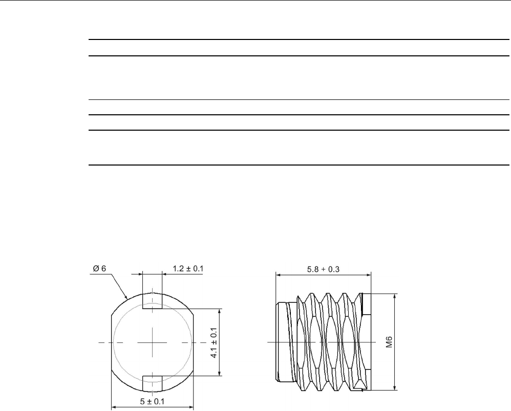
ISO transponder
8.6 MDS D127
SIMATIC RF300
System Manual, 07/2017, C79000-G8976-C345-07 299
6GT2600-0AF00
Design, dimensions and weight
Dimensions (Ø x H)
M6 x 5.8 mm
Weight
1 g
Type of mounting • Glued 2)
• 1 x M3 screw
1)
The values for shock and vibration are maximum values and must not be applied continuously.
2) The processing instructions of the adhesive manufacturer must be observed.
8.6.5
Dimension drawing
Figure 8-13 Dimensions in mm
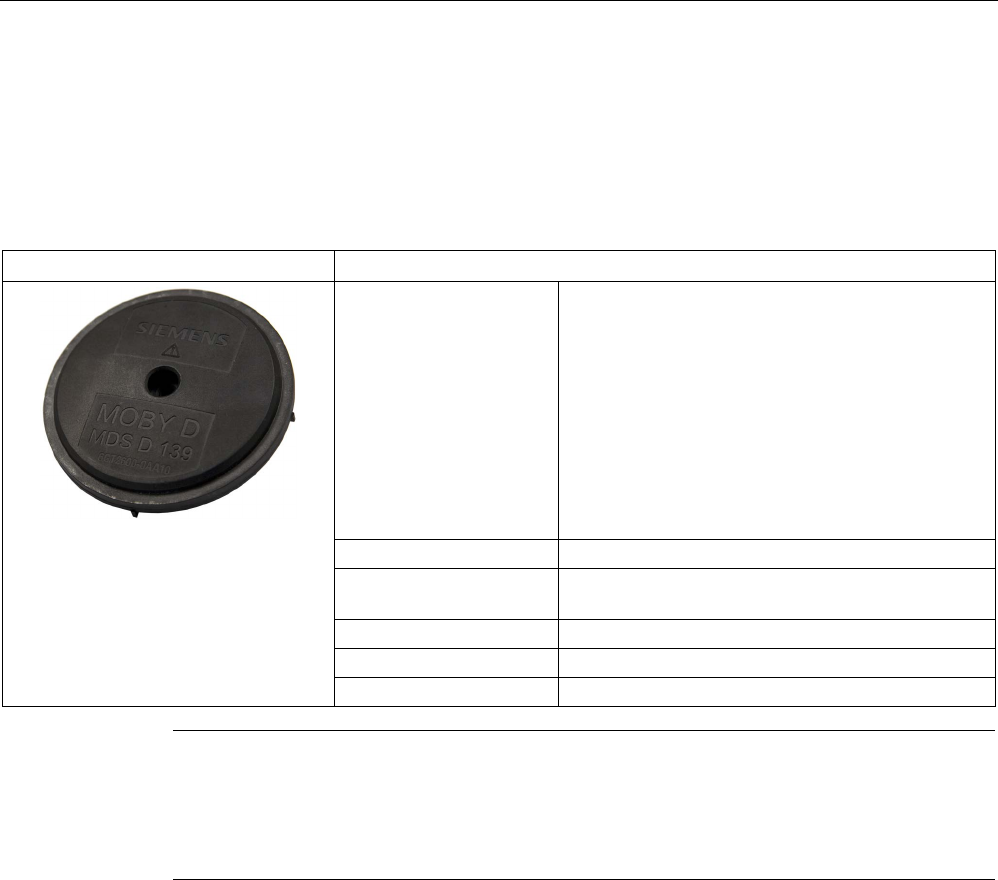
ISO transponder
8.7 MDS D139
SIMATIC RF300
300 System Manual, 07/2017, C79000-G8976-C345-07
8.7
MDS D139
8.7.1
Characteristics
MDS D139
Characteristics
Area of application Applications in production logistics and in assembly
lines subject to high temperatures (up to +220 °C)
Typical application areas:
• Paintshops and their preparatory treatments)
• Primer coat, electrolytic dip area, cataphoresis
with the associated drying furnaces
• Top coat area with drying furnaces
• Washing areas at temperatures > 85 °C
• Other applications with higher temperatures
Memory size 112 bytes of EEPROM user memory
Write/read range See section Field data of ISO transponders (MDS D)
(Page 56).
Mounting on metal
Yes, with spacer
ISO standard
ISO 15693
Degree of protection
IP68/IPx9K
Note
Compatibility with SIMATIC RF300 depending on the article number
The transponder MDS D139 with article number 6GT2600
-0AA10 is compatible with the
SIMATIC RF300 system. The transponder MDS D139 with article number 6GT2600
-0AA00
is not compatible.
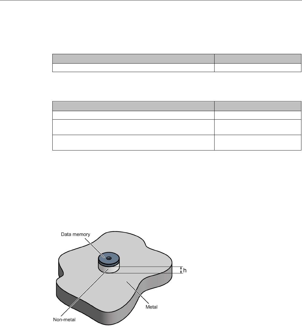
ISO transponder
8.7 MDS D139
SIMATIC RF300
System Manual, 07/2017, C79000-G8976-C345-07 301
8.7.2
Ordering data
Table 8- 15 Ordering data for MDS D139
Article number
MDS D139
6GT2600-0AA10
Table 8- 16 Ordering data for MDS D139 accessory
Article number
Spacer
6GT2690-0AA00
Quick change holder
(Ø x H): 22 x 60 mm
6GT2690-0AH00
Quick change holder
(Ø x H): 22 x 47 mm
6GT2690-0AH10
8.7.3
Mounting on metal
Direct mounting of the MDS D139/D339 on metal is not allowed. A distance of ≥ 30 mm is
recommended. This can be achieved using spacers (see "Ordering data (Page 441)").
Mounting on metal
h
≥ 30 mm
Figure 8-14 Mounting the MDS D139/D339 on metal with spacer
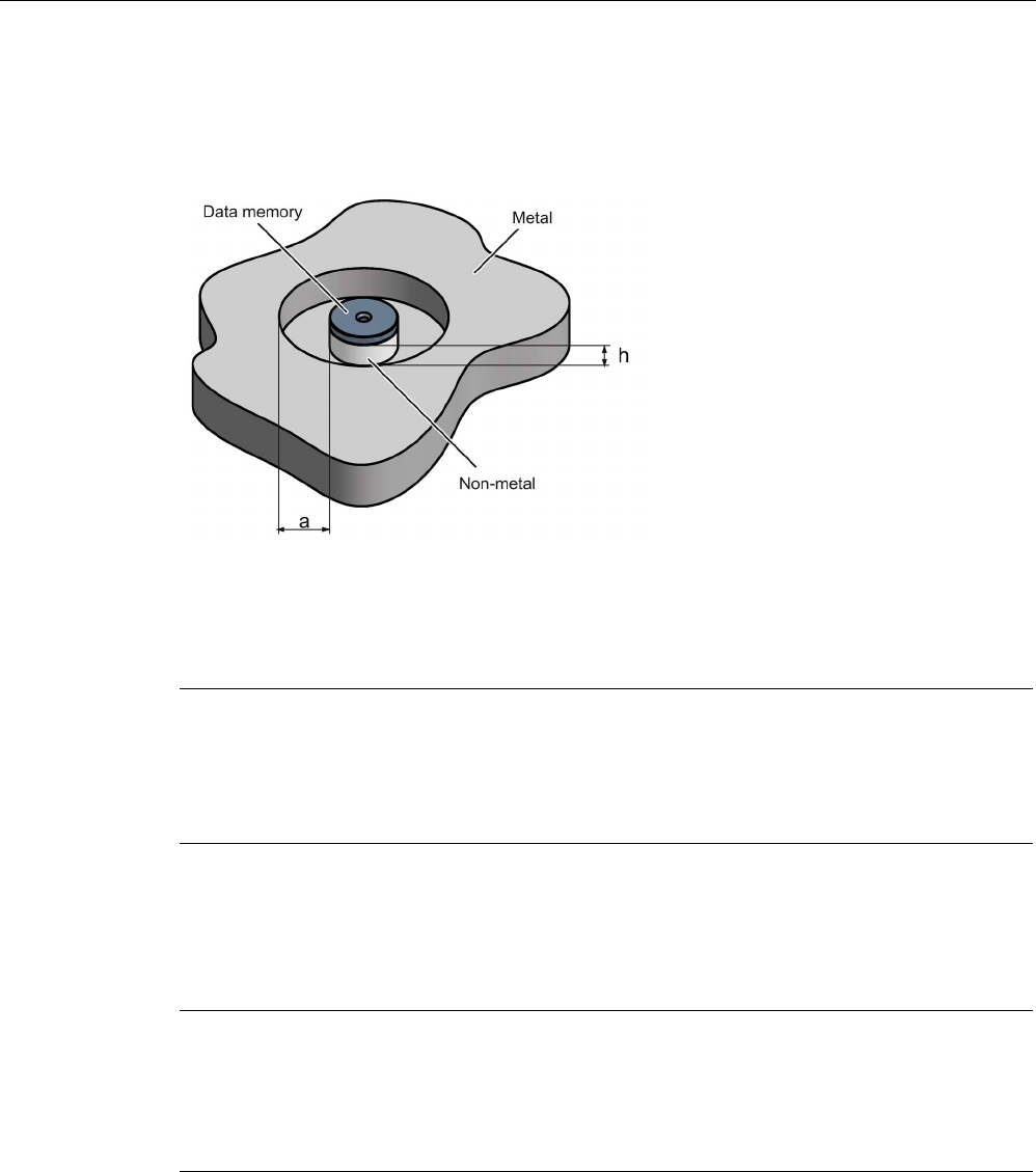
ISO transponder
8.7 MDS D139
SIMATIC RF300
302 System Manual, 07/2017, C79000-G8976-C345-07
Flush-mounting
It is possible to mount the MDS D139/D339 in metal. With large antennas, for example ANT
D5, this leads to a reduction of ranges.
h
≥ 30 mm
a
≥ 100 mm
Figure 8-15 Flush-mounting of the MDS D139/D339 in metal with spacer
Note
Going below the distances
If the distances (a and h) are not observed, a reduction of the field data results. It is possible
to mount the MDS with
metal screws (M5). This has no tangible impact on the range. It is
recommended that a test is performed in critical applications.
8.7.4
Cleaning the mobile data memory
Note
Do not clean the transponder with mechanical tools, sand
-blasting or pressure hose. These
cleaning methods result in damage to the transponder.
Clean the transponder only with the chemical cleansing agents listed in Chapter
Chemical
resistance of the readers and transponders
(Page 97).

ISO transponder
8.7 MDS D139
SIMATIC RF300
System Manual, 07/2017, C79000-G8976-C345-07 303
8.7.5
Technical specifications
Table 8- 17 Technical specifications for MDS D139
6GT2600-0AA10
Product type designation
SIMATIC MDS D139
Memory
Memory configuration
• UID • 8 bytes
• User memory • 112 bytes EEPROM
• OTP memory • 16 bytes (EEPROM)
Read cycles (at < 40 ℃)
> 10
14
Write cycles (at < 40 ℃)
> 10
6
Data retention time (at < 40 ℃)
> 10 years
Write/read distance (Sg) Dependent on the reader used, see section "Field
data of ISO transponders (MDS D) (Page 56)"
MTBF (Mean Time Between Failures)
228 years
Mechanical specifications
Housing
• Material • PPS
• Color • Black
Recommended distance to metal
≥ 30 mm
Power supply
Inductive, without battery
Permitted ambient conditions
Ambient temperature
• during write/read access • -25 … +140 °C
• from +125 ℃: 20% reduction in the limit dis-
tance
• outside the read/write field • -40 to +220 ℃
• at +200 ℃: Tested up to 5000 hours or
6000 cycles
• at +220 ℃: Tested up to 2000 hours or
2000 cycles
• during storage • -40 to +100 ℃

ISO transponder
8.7 MDS D139
SIMATIC RF300
304 System Manual, 07/2017, C79000-G8976-C345-07
6GT2600-0AA10
Degree of protection to EN 60529 • IP68
2 hours, 2 bar, +20 °C
• IPx9K
steam jet: 150 mm; 10 to 15 l/min; 100 bar; 75
°C
Shock according to EN 60721-3-7 Class 7M3
1)
500 m/s
2
Vibration according to EN 60721-3-7 Class 7M3
1)
200 m/s
2
Torsion and bending load
Not permitted
Design, dimensions and weight
Dimensions (Ø x H)
85 x 15 mm
Weight
50 g
Type of mounting 1 x M5 screw 2)
1.5 Nm
1
The values for shock and vibration are maximum values and must not be applied continuously.
2)
For mounting with the spacer (6GT2690-0AA00), use a stainless steel M5 screw to avoid damag-
ing the MDS in high temperatures (expansion coefficient).
8.7.6
Use of the MDS D139 in hazardous areas
The MDS D139 mobile data memory is classed as a piece of simple, electrical equipment
and can be operated in Protection Zone 2, Device Group II, Category 3G.
The following requirements of the 94/9/EC directive are met:
● EN 60079-0:2006
● EN 60079-15:2005
● EN 61241-0:2006
● EN 61241-1:2004
ISO transponder
8.7 MDS D139
SIMATIC RF300
System Manual, 07/2017, C79000-G8976-C345-07 305
Identification
II 3 G Ex nA II T2
II 3 D Ex tD A22 IP68 T 220°C
KEMA 09 ATEX 0133 X
Ta: -25 ... +220°C
WARNING
Gefahr durch elektrostatische Entladungen
Potential electrostatic charging hazard
Danger potentiel de charges électrostatiques
Note
Installations- und Betriebsbedingungen für den Ex-Schutzbereich:
a
) Der Einsatz des Gerätes in der Nähe von stark ladungserzeugenden Prozessen ist
untersagt.
b) Das Gerät ist mechanisch geschützt zu montieren.
c) Die Montage muss auf einem geerdeten, leitenden Untergrund erfolgen.
d) Die Reinigung darf nur mit feuchtem T
uch erfolgen.
Installation and operating conditions for hazardous areas:
a) Use of the equipment in the vicinity of processes generating high charges is not allowed.
b) The equipment must be mechanically protected when installed.
c) Installation must be p
erformed on a grounded and conductive mounting surface.
d) Cleaning only with a wet cloth
Conditions d'installation et de mise en oeuvre pour la zone de protection Ex :
a) L'utilisation de l'appareil près de processus générant de fortes charges est interd
ite.
b) L'appareil doit être monté de manière à être protégé mécaniquement.
c) Le montage doit être effectué sur un socle conducteur mis à la terre.
d) Nettoyage uniquement avec un chiffon humide
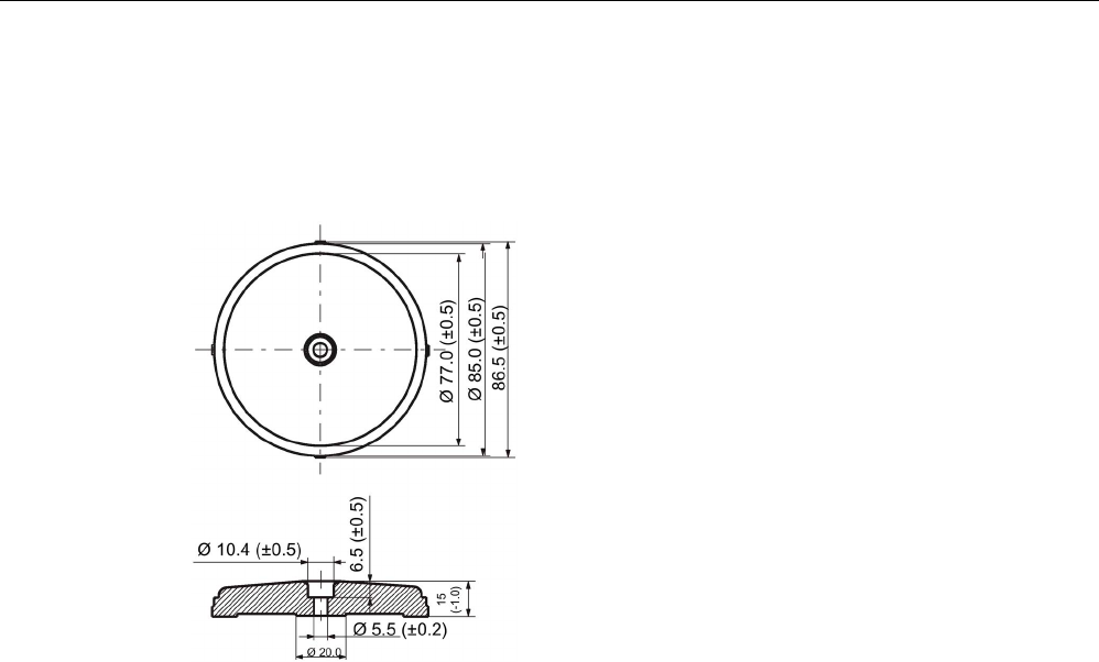
ISO transponder
8.7 MDS D139
SIMATIC RF300
306 System Manual, 07/2017, C79000-G8976-C345-07
8.7.7
Dimension drawings
Dimensional drawing of MDS D139
Figure 8-16 Dimensional drawing of MDS D139
Dimensions in mm