Siemens RF380R02 RFID Reader 13.56 MHz User Manual SIMATIC RF300
Siemens AG RFID Reader 13.56 MHz SIMATIC RF300
UserManual.wiki
>
Siemens
>
RF380R02 User Manual
>
SYH_RF300_76_Part 2
Contents
1.
SYH_RF300_76_Part 1
2.
SYH_RF300_76_Part 2
3.
SYH_RF300_76_Part 3
SYH_RF300_76_Part 2
Navigation menu
Upload a User Manual
Namespaces
Wiki Guide
HTML
PDF
Info
Views
User Manual
Discussion / Help
Navigation
![Readers 5.4 SIMATIC RF340R/RF350R SIMATIC RF300 System Manual, 07/2017, C79000-G8976-C345-07 163 5.4.3 Use of the reader in hazardous areas TÜV NORD CERT GmbH as accredited test center and certification body, no. 0044 as per Article 9 of the Directive 94/9/EC of the European Council of 23 March 1994, has confirmed the compliance with the essential health and safety requirements relating to the design and construction of equipment and protective systems intended for use in hazardous areas as per Annex II of the Directive. The essential health and safety requirements are satisfied in accordance with the following standards: Document Title EN 60079-0: 2006 Electrical equipment for hazardous gas atmospheres - Part 0: General requirements EN 60079-15: 2005 Electrical equipment for hazardous gas atmospheres - Part 15: Design, testing and identification of electrical equipment with type of protection "n" IEC 61241 -0: 2006 Electrical apparatus for use in the presence of combustible dust - Part 0: General requirements IEC 61241 -1: 2004 Electrical apparatus for use in the presence of combustible dust - Part 1: Protection through enclosure WARNING EXPLOSION HAZARD DO NOT CONNECT OR DISCONNECT EQUIPMENT WHEN A FLAMMABLE OR COMBUSTIBLE ATMOSPHERE IS PRESENT. Identification The identification of the electrical equipment as an enclosed unit is: II 3 G Ex nA nC IIB T5 II 3 D Ex tD A22 IP6x T80 °C -25 °C to +70 °C Un = 20 to 30 VDC The equipment also has the following additional markings: XXXYYYZZZ [= serial number, is assigned during production] TÜV 10 ATEX 556039 [= certificate number]](https://usermanual.wiki/Siemens/RF380R02.SYH-RF300-76-Part-2/User-Guide-3570476-Page-7.png)
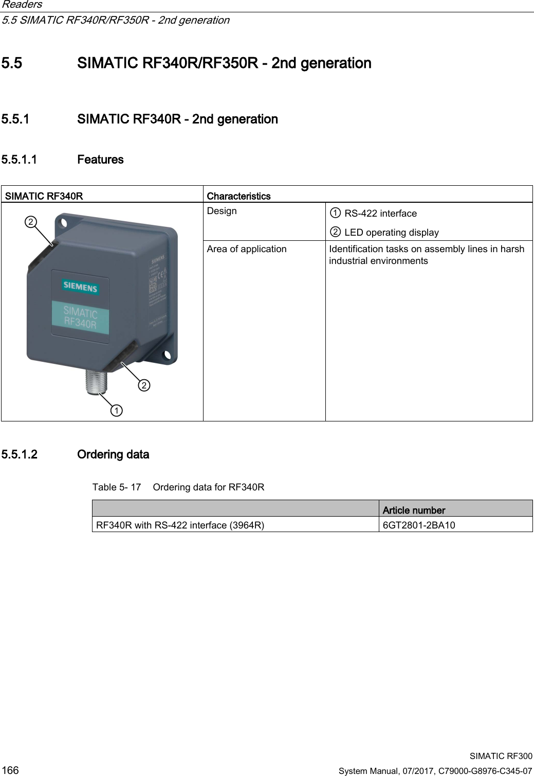
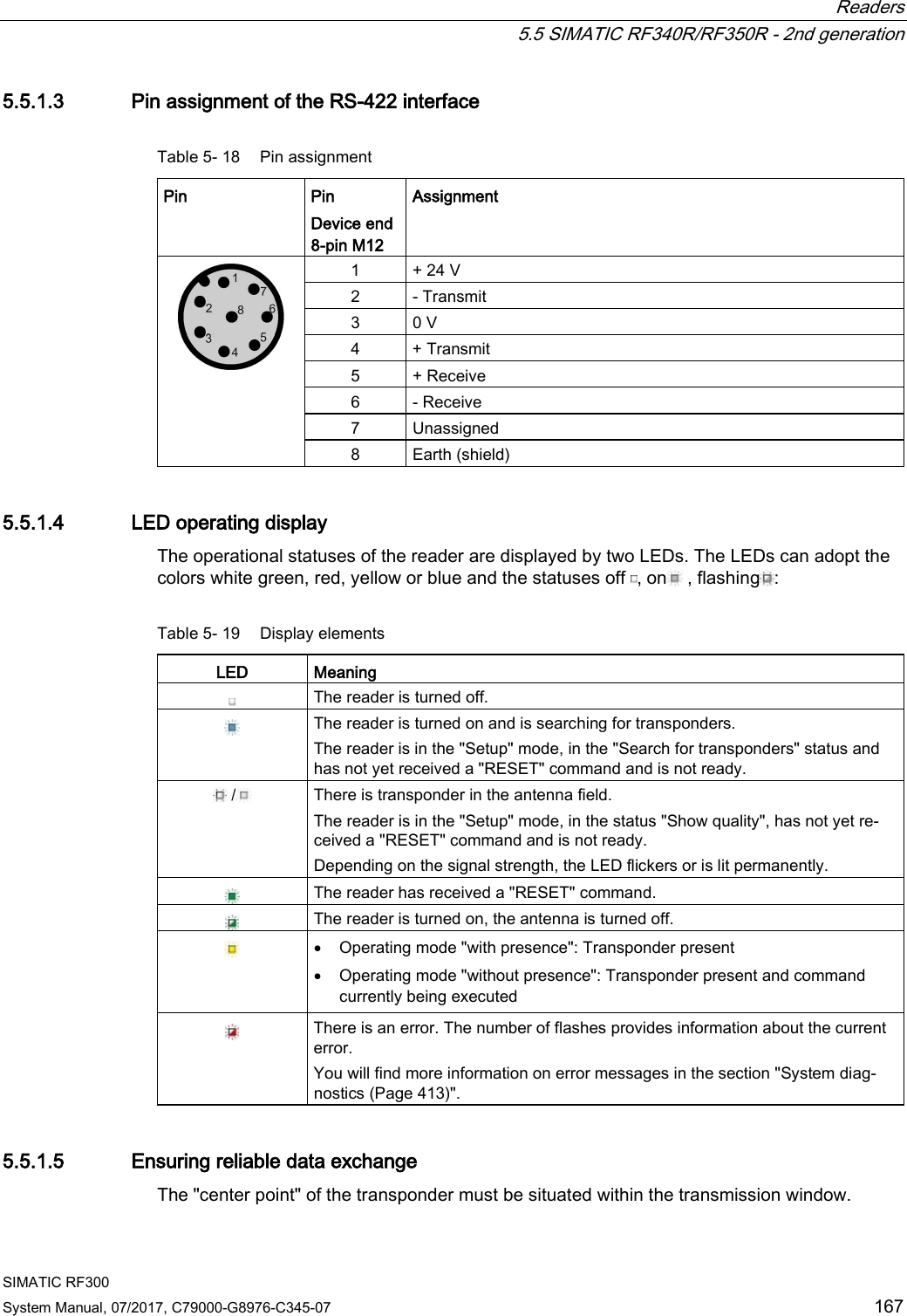
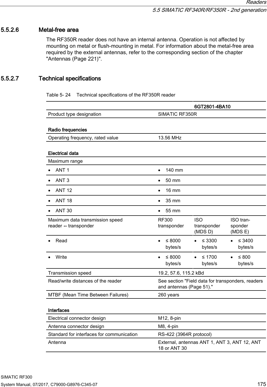

![Readers 5.5 SIMATIC RF340R/RF350R - 2nd generation SIMATIC RF300 System Manual, 07/2017, C79000-G8976-C345-07 179 5.5.3 Using the readers in a hazardous area WARNING Explosion hazard In a flammable or combustible environment, no cables may be connected to or disconnected from the device. ATEX The SIMATIC Ident products meet the requirements of explosion protection acc. to ATEX. The products meet the requirements of the standards: Document Title EN 60079-0 Hazardous areas Part 0: Equipment - General requirements EN 60079-7 Hazardous areas Part 7: Equipment protection by increased safety "e" EN 60079-31 Potentially explosive atmosphere Part 31: Equipment dust ignition protection by enclosure "t" You will find the current versions of the standards in the currently valid ATEX certificates. ATEX mark NOTICE Validity only when the devices are marked There is a corresponding approval only with devices to which the Ex mark is applied. The identification of the electrical equipment as an enclosed unit is: II 3 G Ex ec IIB T4 Gc II 3 D Ex tc IIIC T80°C Dc -25 °C ... +70 °C Un = 24 VDC The equipment also has the following additional information: XXXYYYZZZ [= serial number, is assigned during production] DEMKO 17 ATEX 1767 X [= certificate number]](https://usermanual.wiki/Siemens/RF380R02.SYH-RF300-76-Part-2/User-Guide-3570476-Page-23.png)
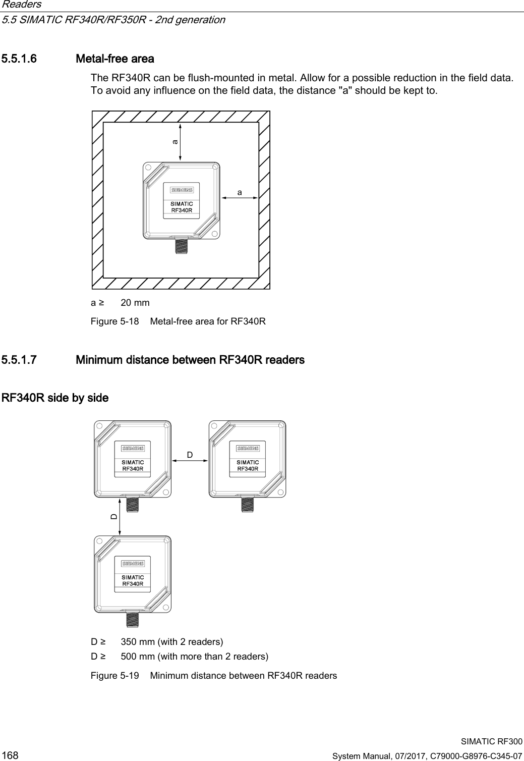
![Readers 5.5 SIMATIC RF340R/RF350R - 2nd generation SIMATIC RF300 180 System Manual, 07/2017, C79000-G8976-C345-07 IECEx The SIMATIC Ident products meet the requirements of explosion protection acc. to IECEx. The products meet the requirements of the standards: Document Title IEC 60079-0 Hazardous areas Part 0: Equipment - General requirements IEC 60079-7 Hazardous areas Part 7: Equipment protection by increased safety "e" IEC 60079-31 Potentially explosive atmosphere Part 31: Equipment dust ignition protection by enclosure "t" You will find the current versions of the standards in the currently valid IECEx certificates. IECEx mark NOTICE Validity only when the devices are marked There is a corresponding approval only with devices to which the IECEx mark is applied. The identification of the electrical equipment as an enclosed unit is: II 3 G Ex ec IIB T4 Gc II 3 D Ex tc IIIC T80°C Dc -25 °C ... +70 °C Un= 24 VDC The equipment also has the following additional information: XXXYYYZZZ [= serial number, is assigned during production] IECEx ULD 17.0031 X [= certificate number]](https://usermanual.wiki/Siemens/RF380R02.SYH-RF300-76-Part-2/User-Guide-3570476-Page-24.png)
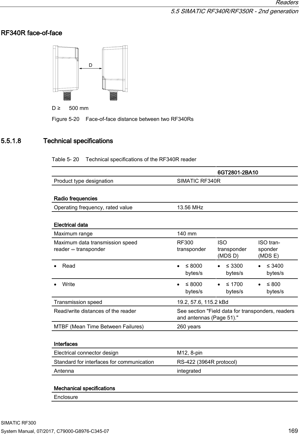
![Readers 5.5 SIMATIC RF340R/RF350R - 2nd generation SIMATIC RF300 System Manual, 07/2017, C79000-G8976-C345-07 181 UL HAZ. LOC. The SIMATIC Ident products meet the requirements of explosion protection acc. to UL HAZ. LOC. The products meet the requirements of the standards: Document Title UL 60079-0 Hazardous areas Part 0: Equipment - General requirements CSA C22.2 NO. 60079-0 UL 60079-7 Hazardous areas Part 7: Equipment protection by increased safety "e" CSA C22.2 NO. 60079-7 UL 60079-31 Potentially explosive atmosphere Part 31: Equipment dust ignition protection by enclosure "t" CSA C22.2 NO. 60079-31 You will find the current versions of the standards in the currently valid UL HAZ. LOC. certificates UL HAZ. LOC. mark NOTICE Validity only when the devices are marked There is a corresponding approval only with devices to which the UL HAZ. LOC. mark is applied. The identification of the electrical equipment as an enclosed unit is: E223122 IND.CONT.EQ FOR HAZ.LOC. CL.I, DIV.2, GP.C,D T4 CL.II, DIV.2, GP.F,G T80°C AEx ec IIB T4, Ex ec IIB T4 AEx tc IIIC T80°C, Ex tc IIIC T80°C -25 °C ... +70 °C Un= 24 VDC The equipment also has the following additional information: XXXYYYZZZ [= serial number, is assigned during production]](https://usermanual.wiki/Siemens/RF380R02.SYH-RF300-76-Part-2/User-Guide-3570476-Page-25.png)
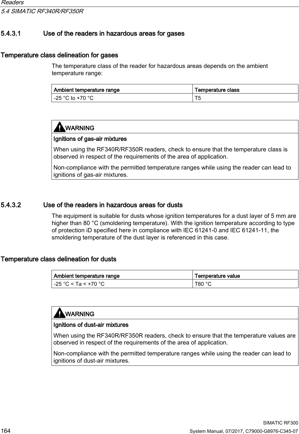
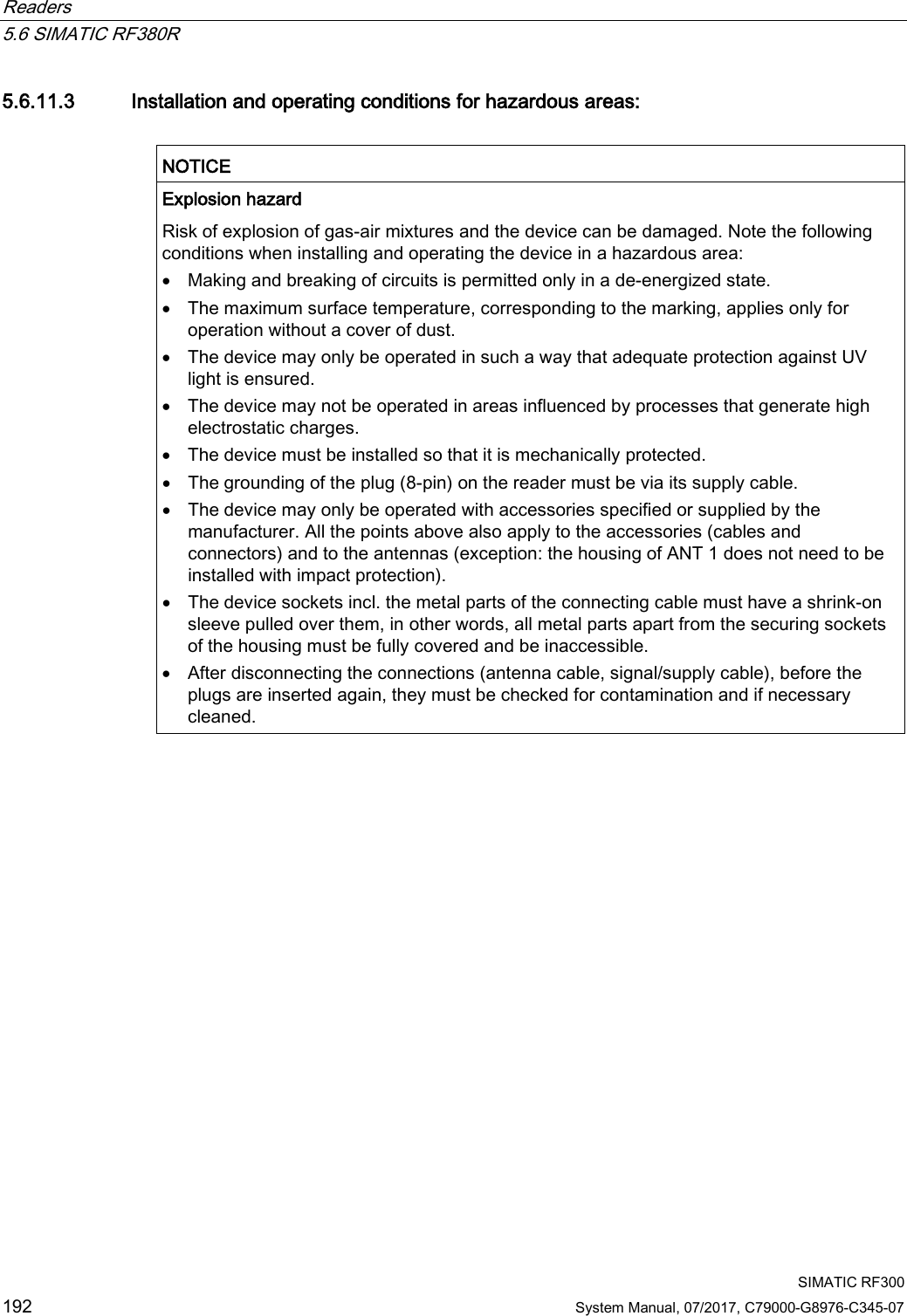
![Readers 5.6 SIMATIC RF380R SIMATIC RF300 System Manual, 07/2017, C79000-G8976-C345-07 191 Identification The identification of the electrical equipment as an enclosed unit is: II 3G Ex nC IIB T5 -25°C to +70°C Um=30 V DC The equipment is assigned the following references: XXXYYYZZZ [= serial number, is assigned during production] TPS 09 ATEX 1 459 X [= certificate number] "No use of the equipment in the vicinity of processes generating high charges" "Do not disconnect plug on load" 5.6.11.2 Use of the reader in hazardous areas for gases Temperature class grading for gases The temperature class of the reader for hazardous areas depends on the ambient temperature range: Ambient temperature range Temperature class -25 °C to +70 °C T5 WARNING Ignitions of gas-air mixtures When using the RF380R reader, check to ensure that the temperature class is observed in respect of the requirements of the area of application Non-compliance with the permitted temperature ranges while using the reader can lead to ignitions of gas-air mixtures.](https://usermanual.wiki/Siemens/RF380R02.SYH-RF300-76-Part-2/User-Guide-3570476-Page-35.png)
![Readers 5.8 SIMATIC RF380R - 2nd generation SIMATIC RF300 208 System Manual, 07/2017, C79000-G8976-C345-07 ATEX The SIMATIC Ident products meet the requirements of explosion protection acc. to ATEX. The products meet the requirements of the standards: Document Title EN 60079-0 Hazardous areas Part 0: Equipment - General requirements EN 60079-7 Hazardous areas Part 7: Equipment protection by increased safety "e" EN 60079-31 Potentially explosive atmosphere Part 31: Equipment dust ignition protection by enclosure "t" You will find the current versions of the standards in the currently valid ATEX certificates. ATEX mark NOTICE Validity only when the devices are marked There is a corresponding approval only with devices to which the Ex mark is applied. The identification of the electrical equipment as an enclosed unit is: II 3 G Ex ec IIB T4 Gc II 3 D Ex tc IIIC T80°C Dc -25 °C ... +70 °C Un = 24 VDC The equipment also has the following additional information: XXXYYYZZZ [= serial number, is assigned during production] DEMKO 17 ATEX 1767 X [= certificate number]](https://usermanual.wiki/Siemens/RF380R02.SYH-RF300-76-Part-2/User-Guide-3570476-Page-52.png)
![Readers 5.8 SIMATIC RF380R - 2nd generation SIMATIC RF300 System Manual, 07/2017, C79000-G8976-C345-07 209 IECEx The SIMATIC Ident products meet the requirements of explosion protection acc. to IECEx. The products meet the requirements of the standards: Document Title IEC 60079-0 Hazardous areas Part 0: Equipment - General requirements IEC 60079-7 Hazardous areas Part 7: Equipment protection by increased safety "e" IEC 60079-31 Potentially explosive atmosphere Part 31: Equipment dust ignition protection by enclosure "t" You will find the current versions of the standards in the currently valid IECEx certificates. IECEx mark NOTICE Validity only when the devices are marked There is a corresponding approval only with devices to which the IECEx mark is applied. The identification of the electrical equipment as an enclosed unit is: II 3 G Ex ec IIB T4 Gc II 3 D Ex tc IIIC T80°C Dc -25 °C ... +70 °C Un= 24 VDC The equipment also has the following additional information: XXXYYYZZZ [= serial number, is assigned during production] IECEx ULD 17.0031 X [= certificate number] UL HAZ. LOC. The SIMATIC Ident products meet the requirements of explosion protection acc. to UL HAZ. LOC. The products meet the requirements of the standards: Document Title UL 60079-0 Hazardous areas Part 0: Equipment - General requirements CSA C22.2 NO. 60079-0 UL 60079-7 Hazardous areas Part 7: Equipment protection by increased safety "e" CSA C22.2 NO. 60079-7 UL 60079-31 Potentially explosive atmosphere Part 31: Equipment dust ignition protection by enclosure "t" CSA C22.2 NO. 60079-31](https://usermanual.wiki/Siemens/RF380R02.SYH-RF300-76-Part-2/User-Guide-3570476-Page-53.png)
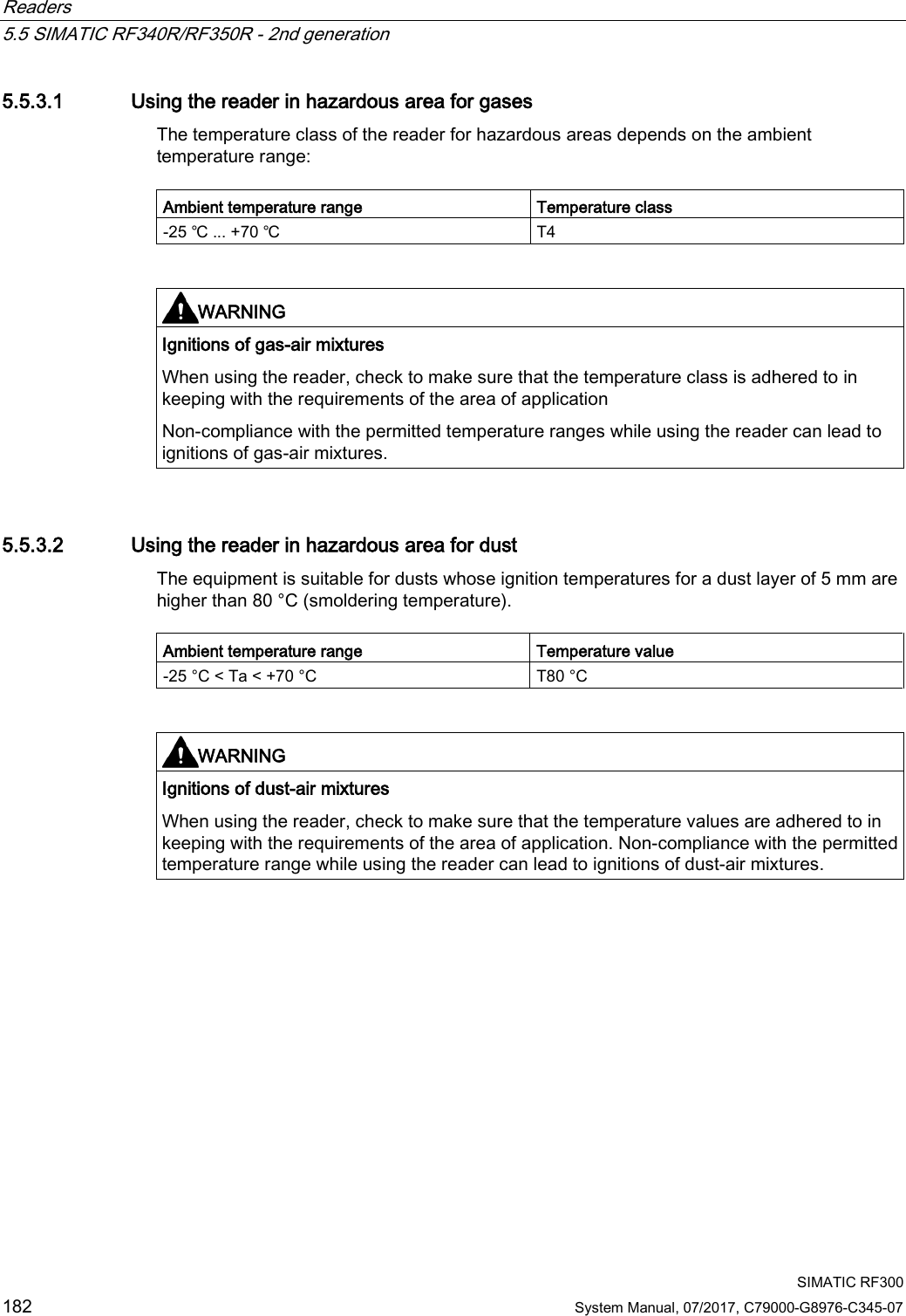
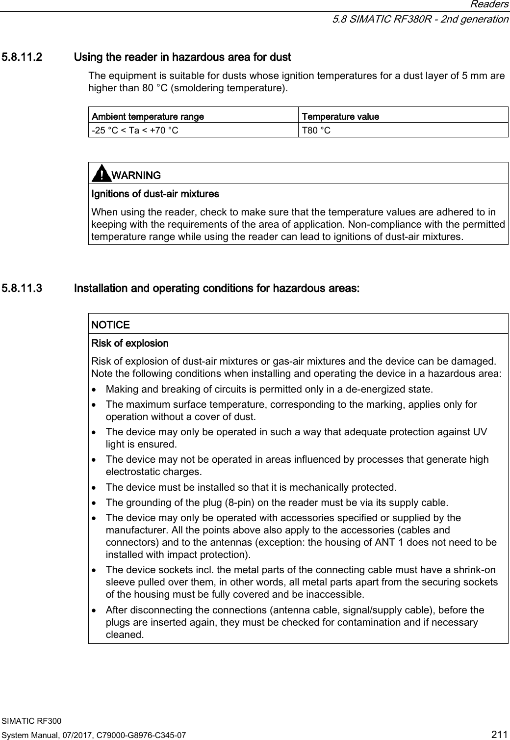
![Readers 5.8 SIMATIC RF380R - 2nd generation SIMATIC RF300 210 System Manual, 07/2017, C79000-G8976-C345-07 You will find the current versions of the standards in the currently valid UL HAZ. LOC. certificates UL HAZ. LOC. mark NOTICE Validity only when the devices are marked There is a corresponding approval only with devices to which the UL HAZ. LOC. mark is applied. The identification of the electrical equipment as an enclosed unit is: E223122 IND.CONT.EQ FOR HAZ.LOC. CL.I, DIV.2, GP.C,D T4 CL.II, DIV.2, GP.F,G T80°C AEx ec IIB T4, Ex ec IIB T4 AEx tc IIIC T80°C, Ex tc IIIC T80°C -25 °C ... +70 °C Un= 24 VDC The equipment also has the following additional information: XXXYYYZZZ [= serial number, is assigned during production] 5.8.11.1 Using the reader in hazardous area for gases The temperature class of the reader for hazardous areas depends on the ambient temperature range: Ambient temperature range Temperature class -25 ℃ ... +70 ℃ T4 WARNING Ignitions of gas-air mixtures When using the reader, check to make sure that the temperature class is adhered to in keeping with the requirements of the area of application Non-compliance with the permitted temperature ranges while using the reader can lead to ignitions of gas-air mixtures.](https://usermanual.wiki/Siemens/RF380R02.SYH-RF300-76-Part-2/User-Guide-3570476-Page-54.png)
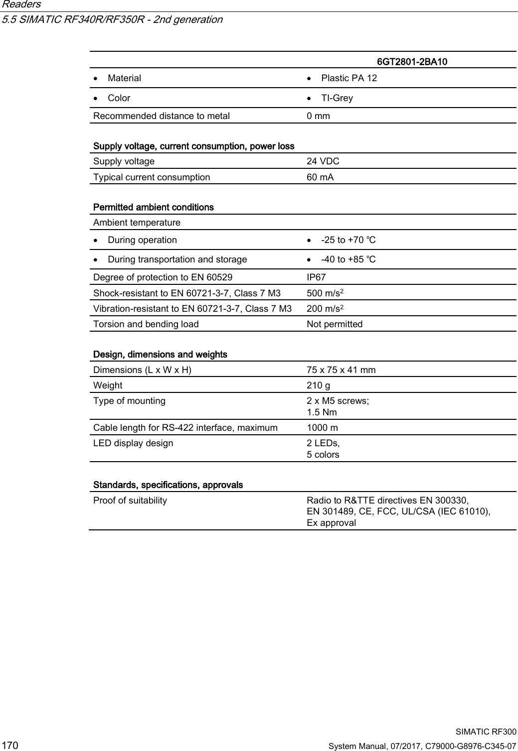
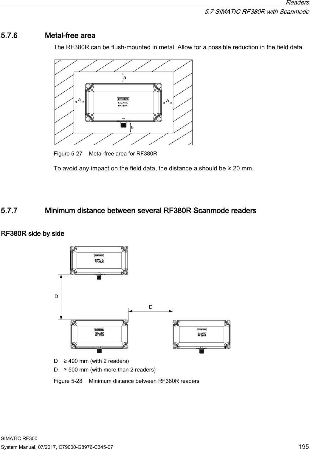
![Antennas 6.5 Minimum distance between antennas SIMATIC RF300 228 System Manual, 07/2017, C79000-G8976-C345-07 6.5 Minimum distance between antennas Table 6- 3 Minimum distance between antennas Diagram (example) Minimum distance [mm] Antennas next to each other ANT 1 D ≥ 300 mm ANT 3 D ≥ 150 mm ANT 3S D ≥ 20 mm ANT 8 D ≥ 50 mm ANT 12 D ≥ 70 mm ANT 18 D ≥ 100 mm ANT 30 D ≥ 100 mm Antennas face to face ANT 1 D ≥ 500 mm ANT 3 D ≥ 200 mm ANT 3S D ≥ 50 mm ANT 8 D ≥ 50 mm ANT 12 D ≥ 100 mm ANT 18 D ≥ 100 mm ANT 30 D ≥ 200 mm The reader electronics can be mounted directly alongside each other.](https://usermanual.wiki/Siemens/RF380R02.SYH-RF300-76-Part-2/User-Guide-3570476-Page-72.png)

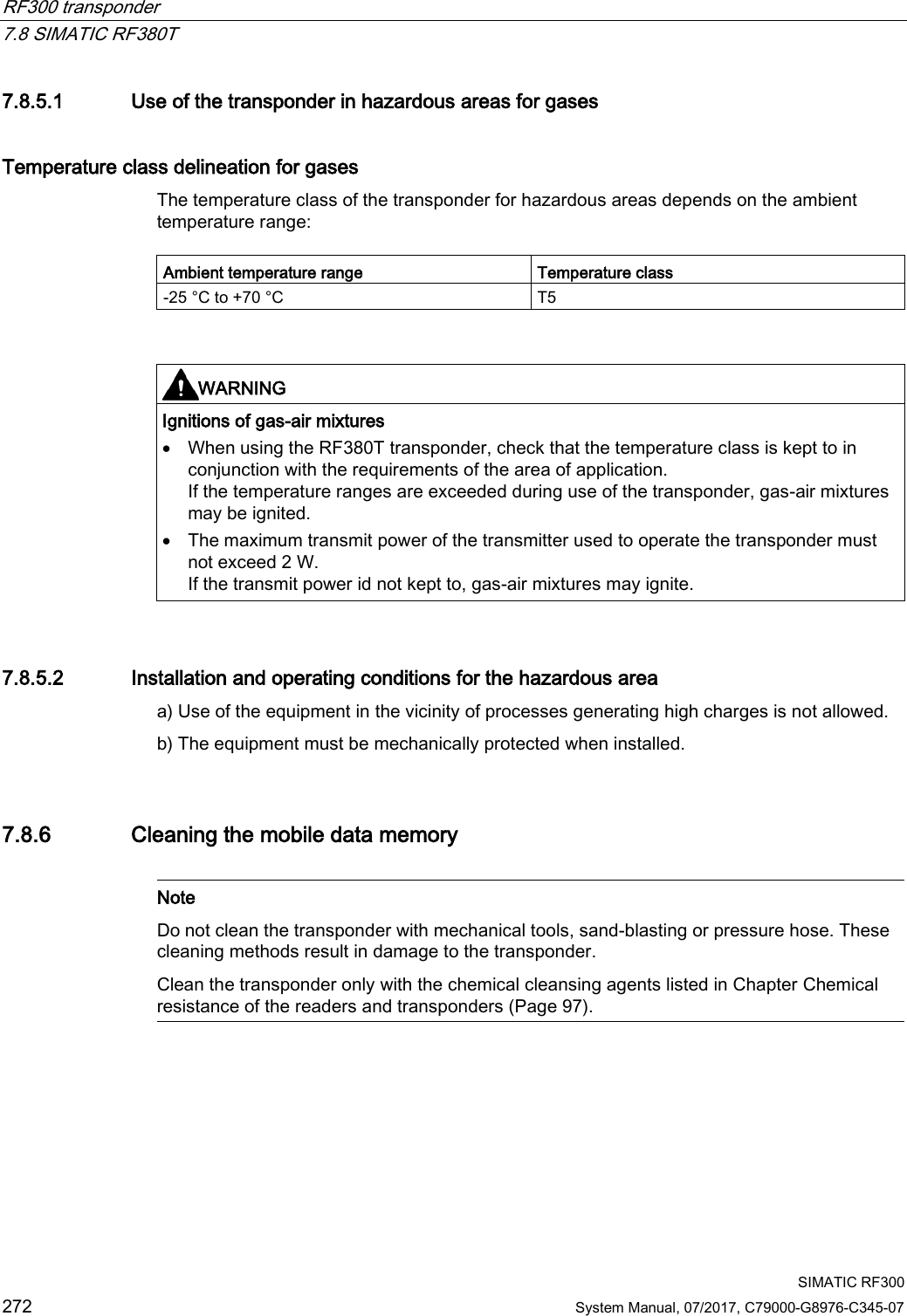
![RF300 transponder 7.8 SIMATIC RF380T SIMATIC RF300 System Manual, 07/2017, C79000-G8976-C345-07 271 7.8.5 Use of the transponder in the Ex protection area The TÜV SÜD Automotive GmbH as approved test center as well as the TÜV SÜD Product Service GmbH as certification center, identification number 0123, as per Article 9 of the Directive of the European Council of 23 March 1994 (94/9/EC), has confirmed the compliance with the essential health and safety requirements relating to the design and construction of equipment and protective systems intended for use in hazardous areas as per Annex II of the Directive. The essential health and safety requirements are satisfied in accordance with the following standards: Table 7- 22 Approvals Document Title EN 60079-0: 2006 Electrical equipment for hazardous gas atmospheres - Part 0: General requirements EN 60079-15: 2005 Electrical equipment for hazardous gas atmospheres - Part 15: Design, testing and identification of electrical equipment with type of protection "n" DIN VDE 0848-5: 2001 (in parts) Safety in electrical, magnetic and electromagnetic fields - Part 5: Explosion protection ZLS SK 107.1 Central office of the states for safety; test components Identification Table 7- 23 The identification of the electrical equipment as an encapsulated unit II 3G Ex nC IIB T5 -25°C to +70°C Um=30Vdc The equipment is assigned the following references: XXXYYYZZZ [= serial number, is assigned during production] TPS 09 ATEX 1 459 X [= certificate number] "No use of the equipment in the vicinity of processes generating high charges"](https://usermanual.wiki/Siemens/RF380R02.SYH-RF300-76-Part-2/User-Guide-3570476-Page-115.png)