Siemens RF380R02 RFID Reader 13.56 MHz User Manual SIMATIC RF300
Siemens AG RFID Reader 13.56 MHz SIMATIC RF300
UserManual.wiki
>
Siemens
>
RF380R02 User Manual
>
SYH_RF300_76_Part 3
Contents
1.
SYH_RF300_76_Part 1
2.
SYH_RF300_76_Part 2
3.
SYH_RF300_76_Part 3
SYH_RF300_76_Part 3
Navigation menu
Upload a User Manual
Namespaces
Wiki Guide
HTML
PDF
Info
Views
User Manual
Discussion / Help
Navigation
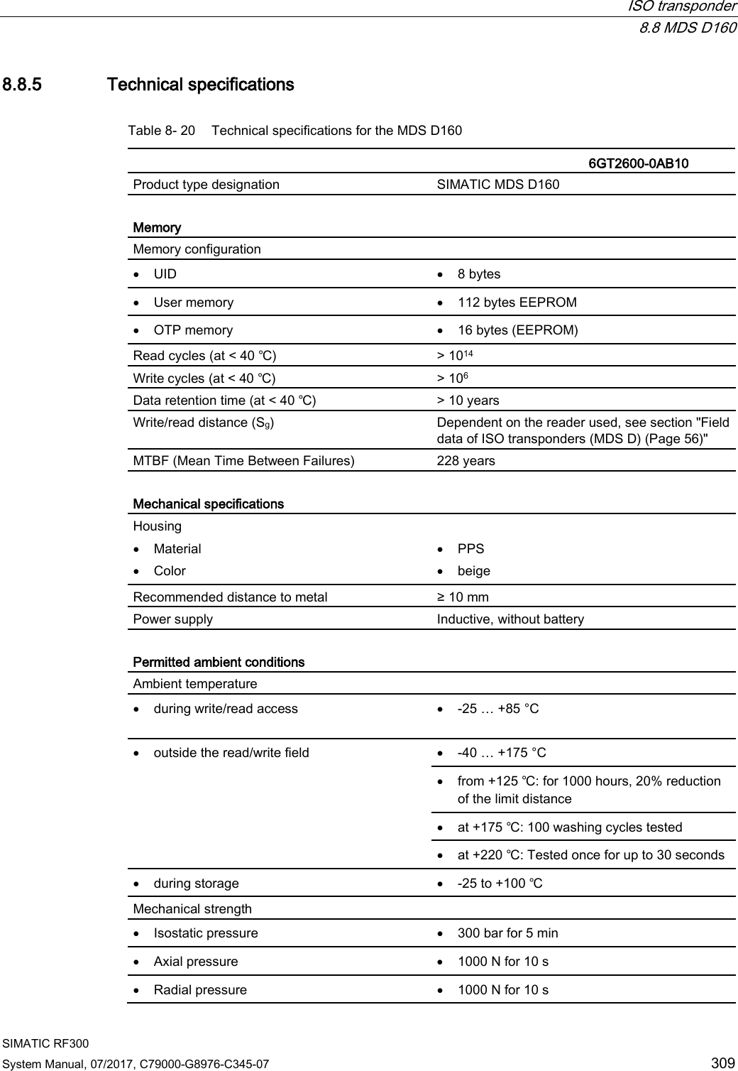
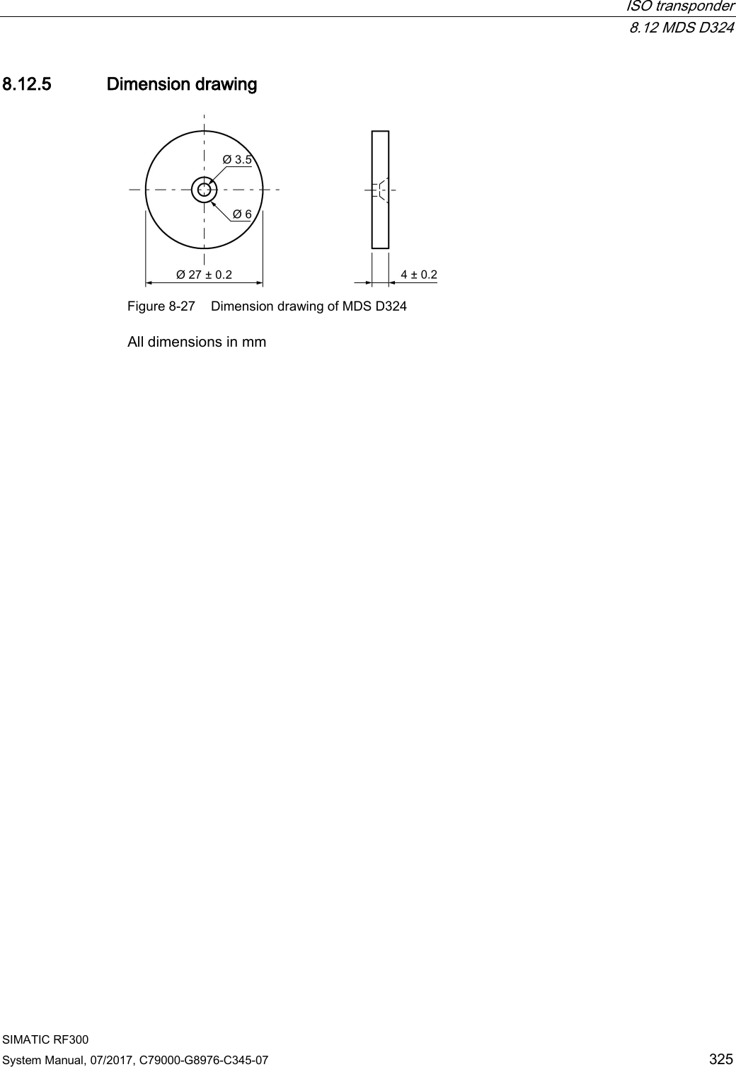
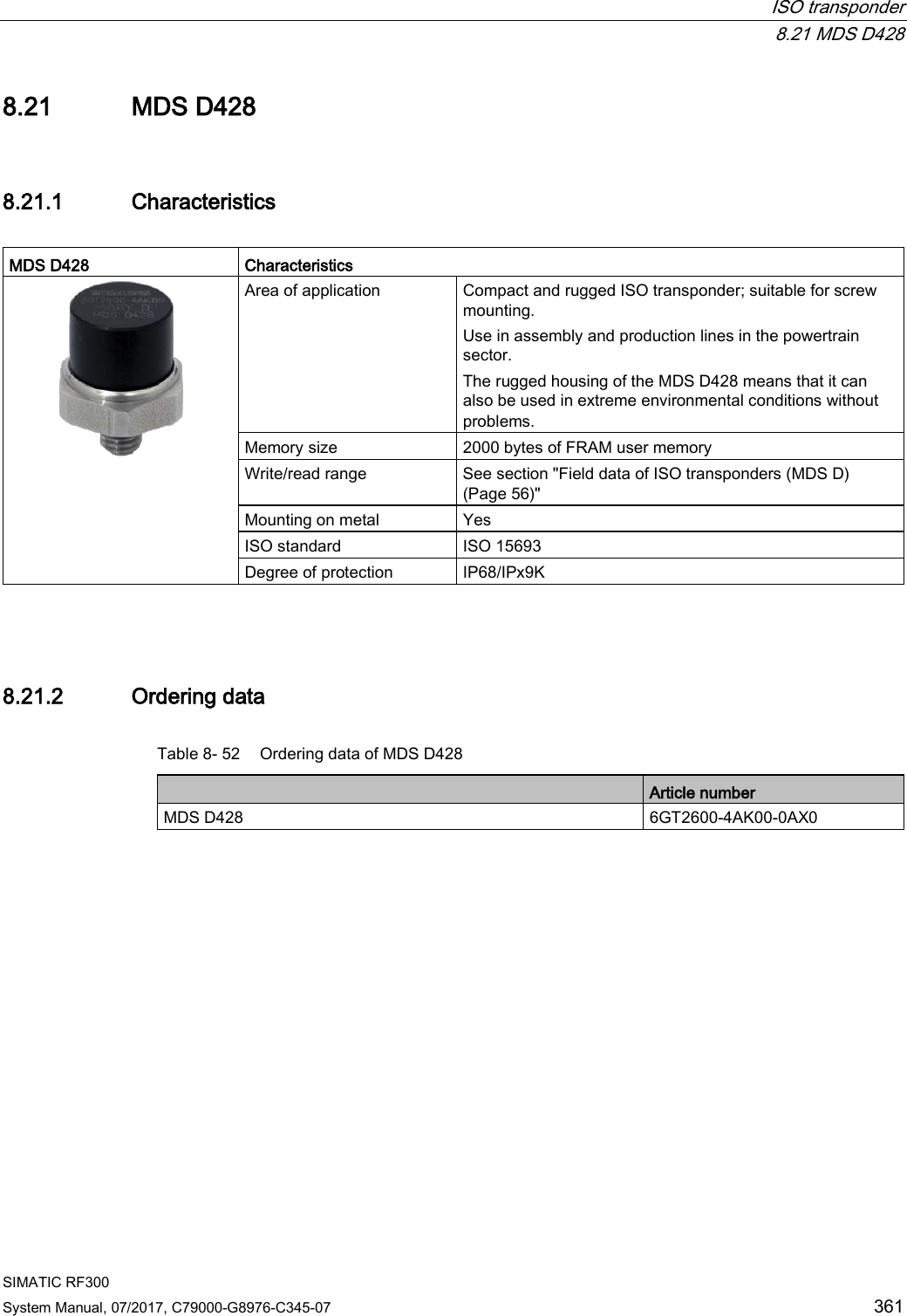
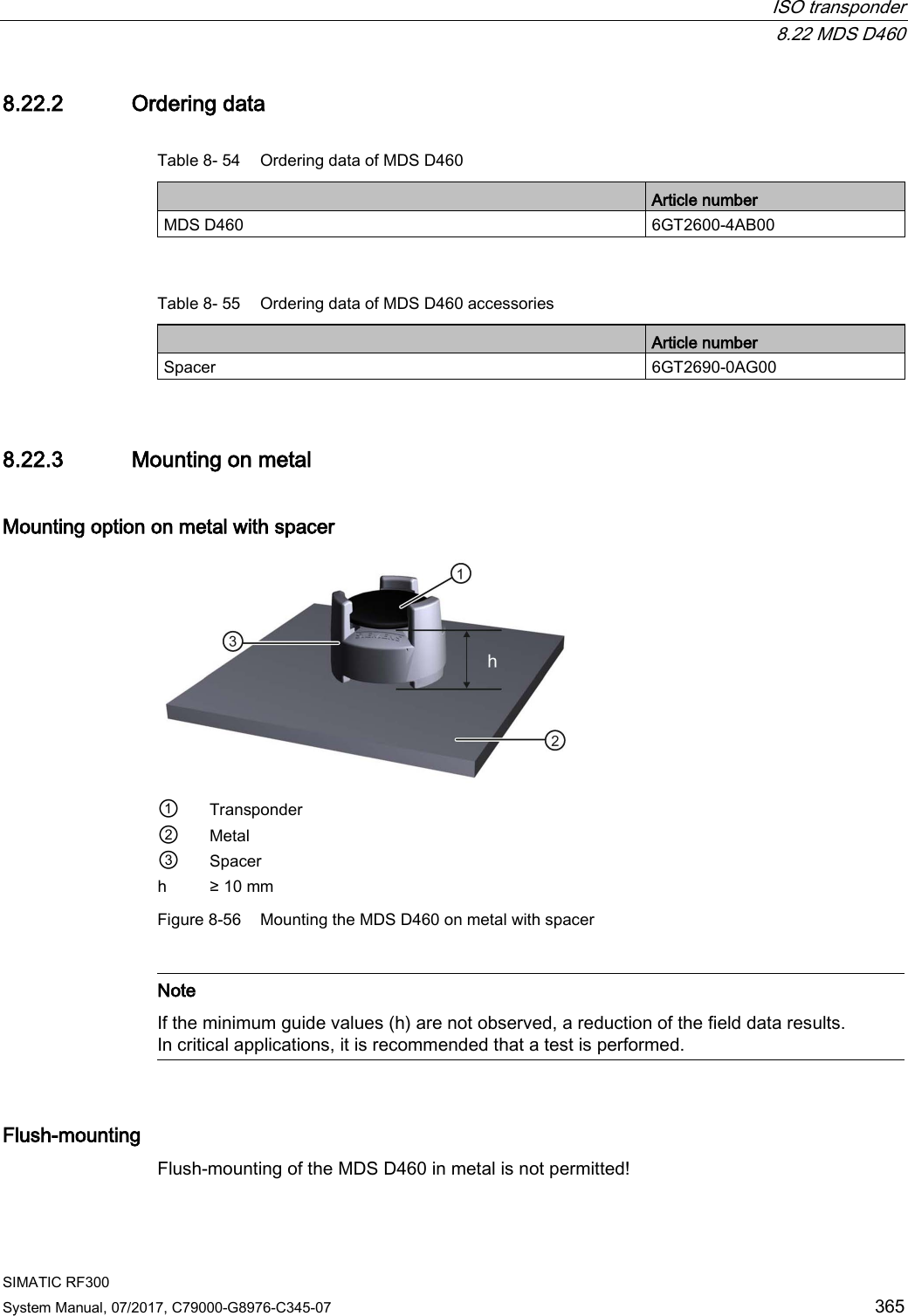
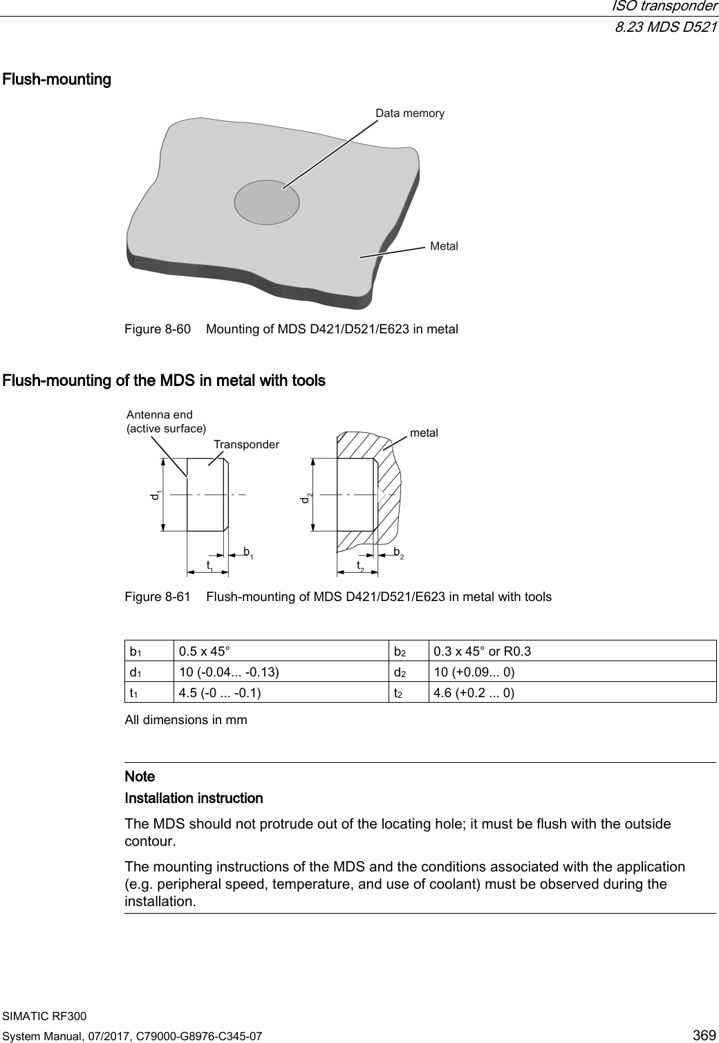
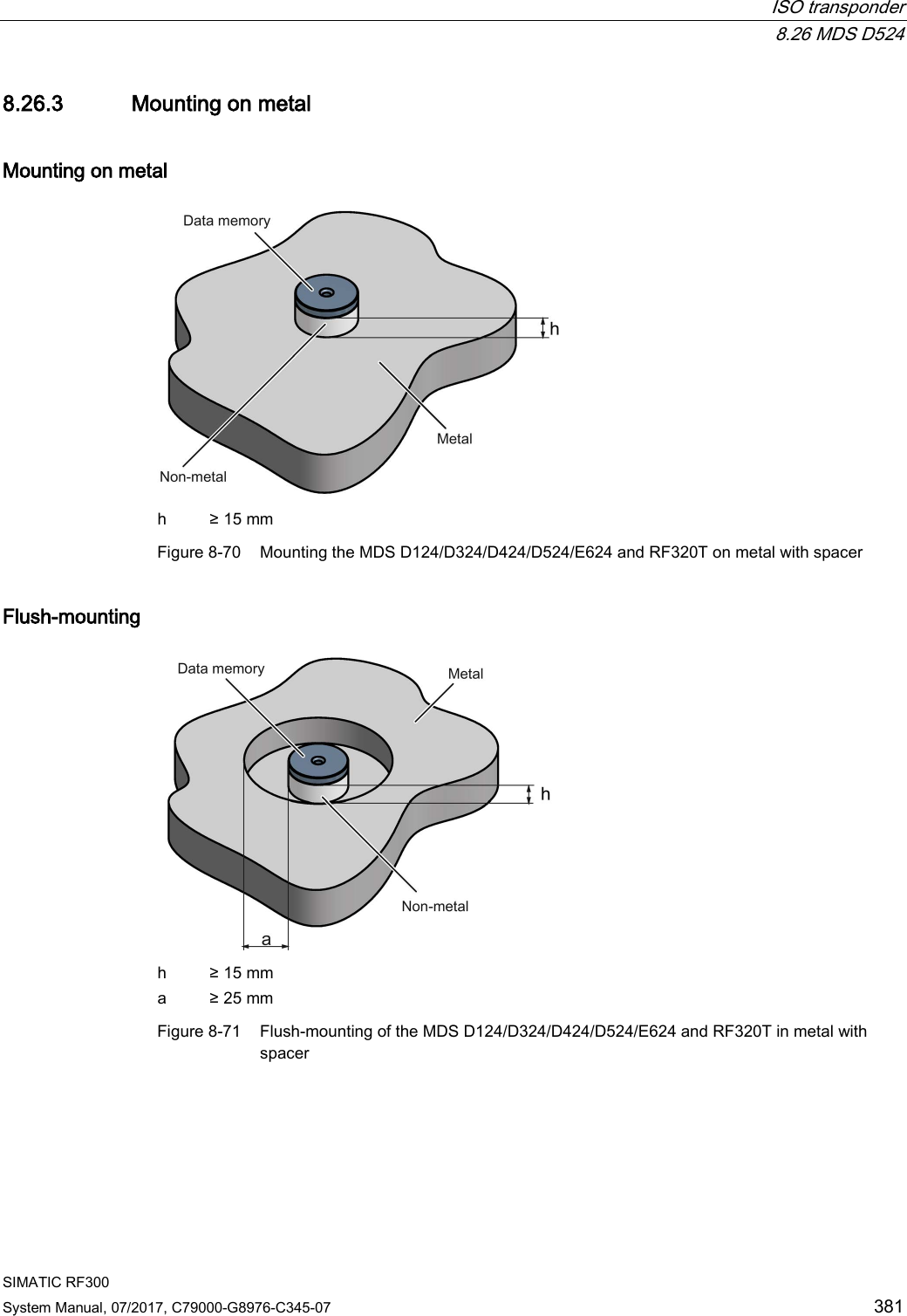
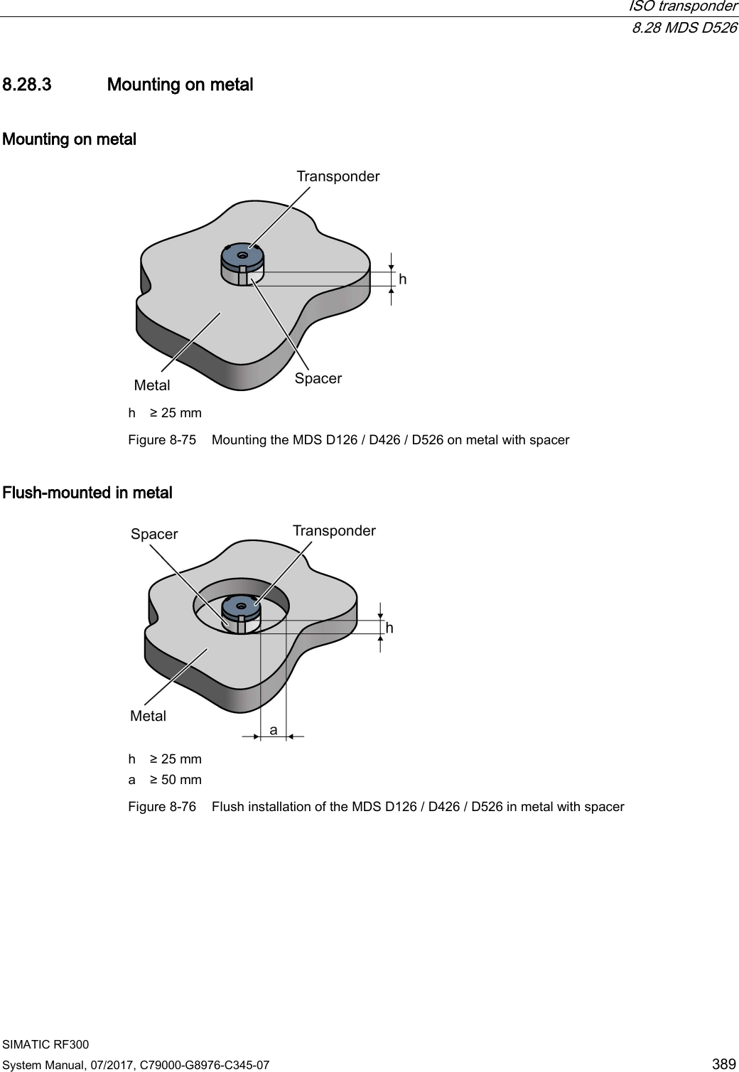
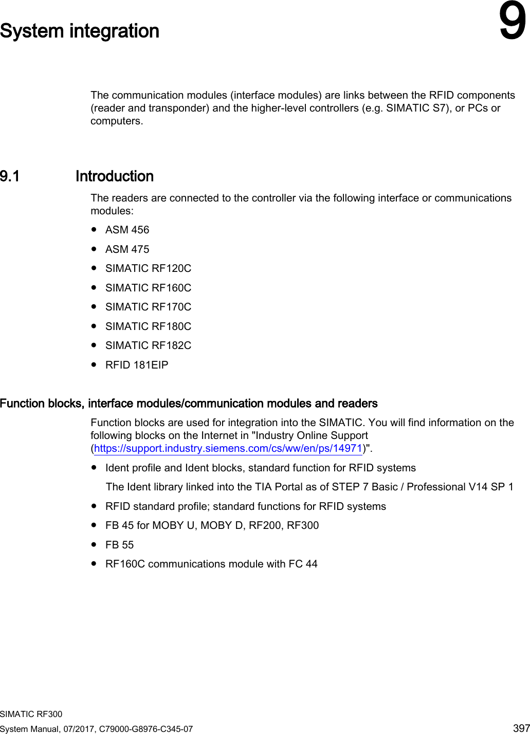
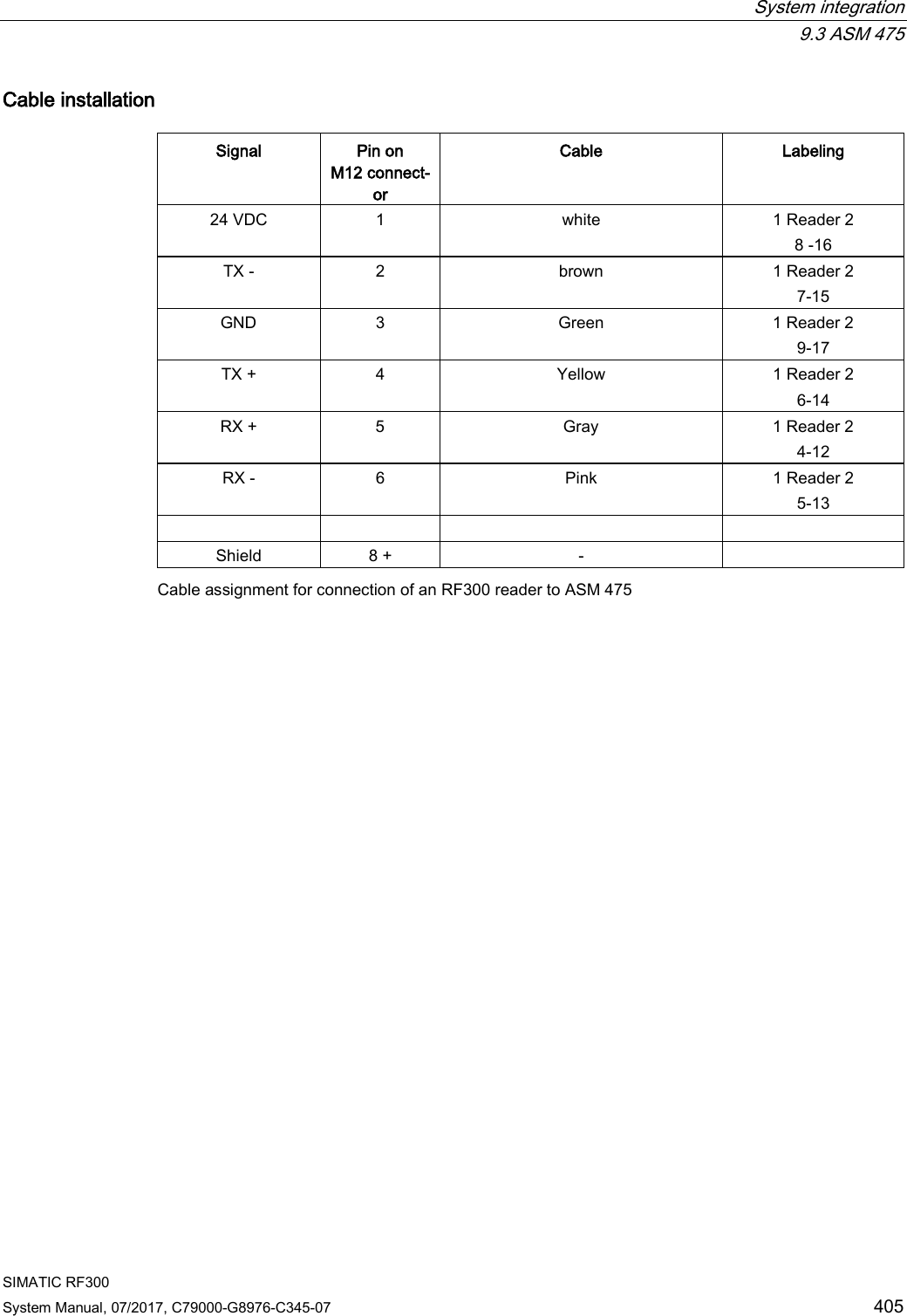
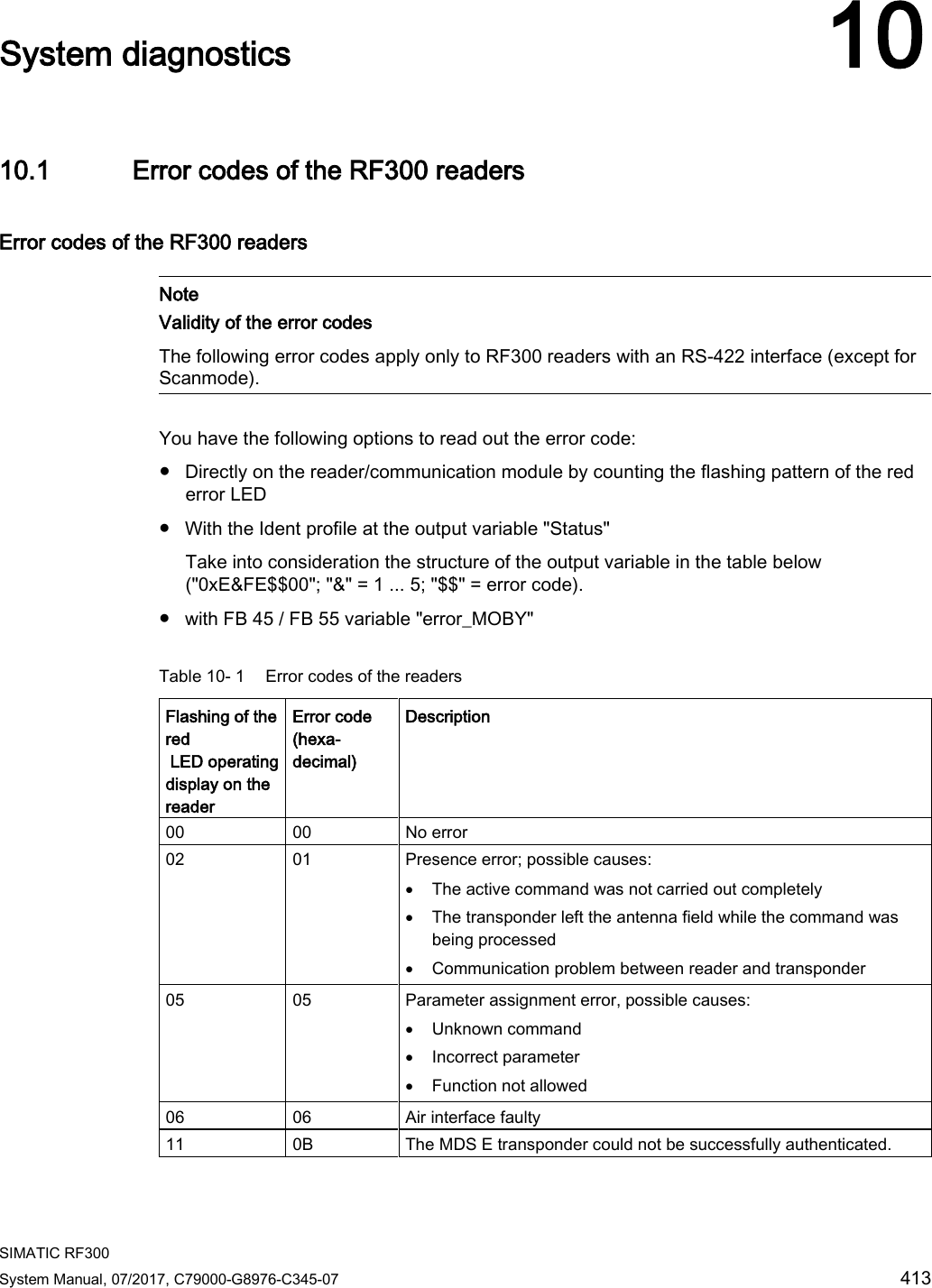
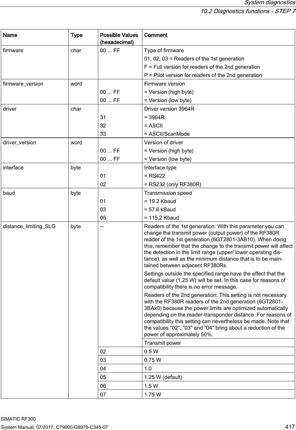
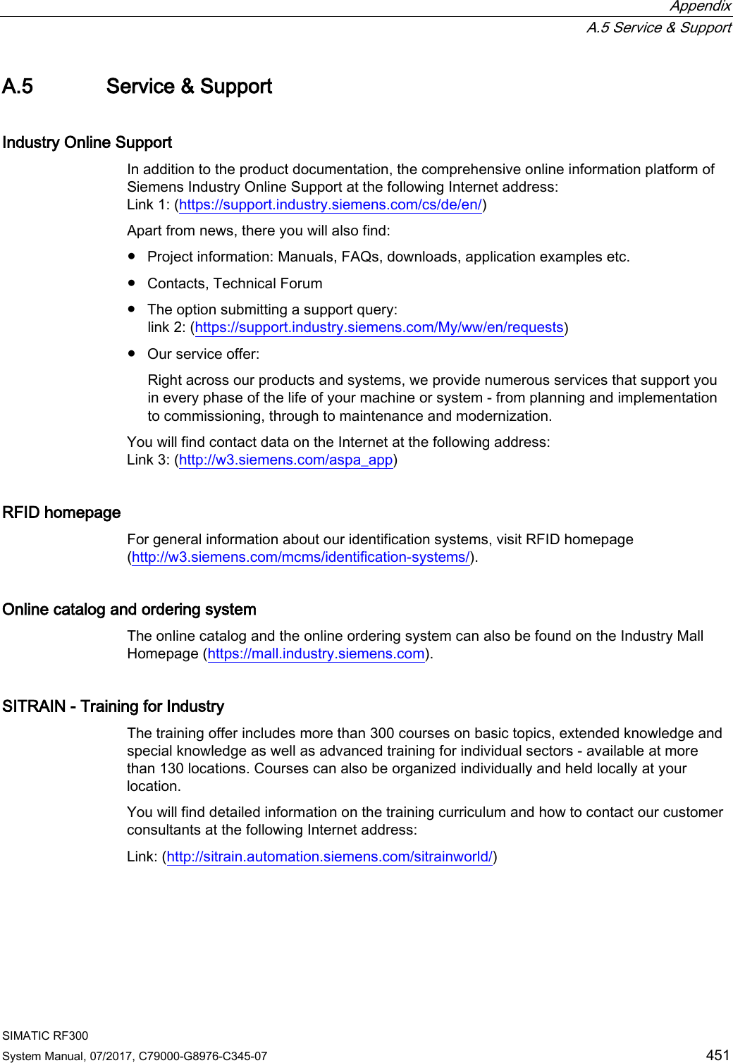
![System diagnostics 10.2 Diagnostics functions - STEP 7 SIMATIC RF300 420 System Manual, 07/2017, C79000-G8976-C345-07 10.2.3 Transponder diagnostics with "Tag status" (MDS-STATUS) With this command you can query the status and diagnostics data from the transponder currently located in the antenna field. Attribute "0x04" (mode 01), corresponds to UDT 260 (only for RF300 transponders) Name Type Possible Values (hex-adecimal) Comment UID array[1…8] byte 000000005555555 ... 00000000FFFFFFFF Unique identifier = b0-31: 4 byte TAG ID, b32-63: 0 MDS_type byte 01 02 03 04 Transponder memory configuration = Transponder without FRAM = Transponder with FRAM 8 KB = Transponder with FRAM 32 KB = Transponder with FRAM 64 KB Lock_state byte 0 ... FF EEPROM write protection status](https://usermanual.wiki/Siemens/RF380R02.SYH-RF300-76-Part-3/User-Guide-3570477-Page-114.png)
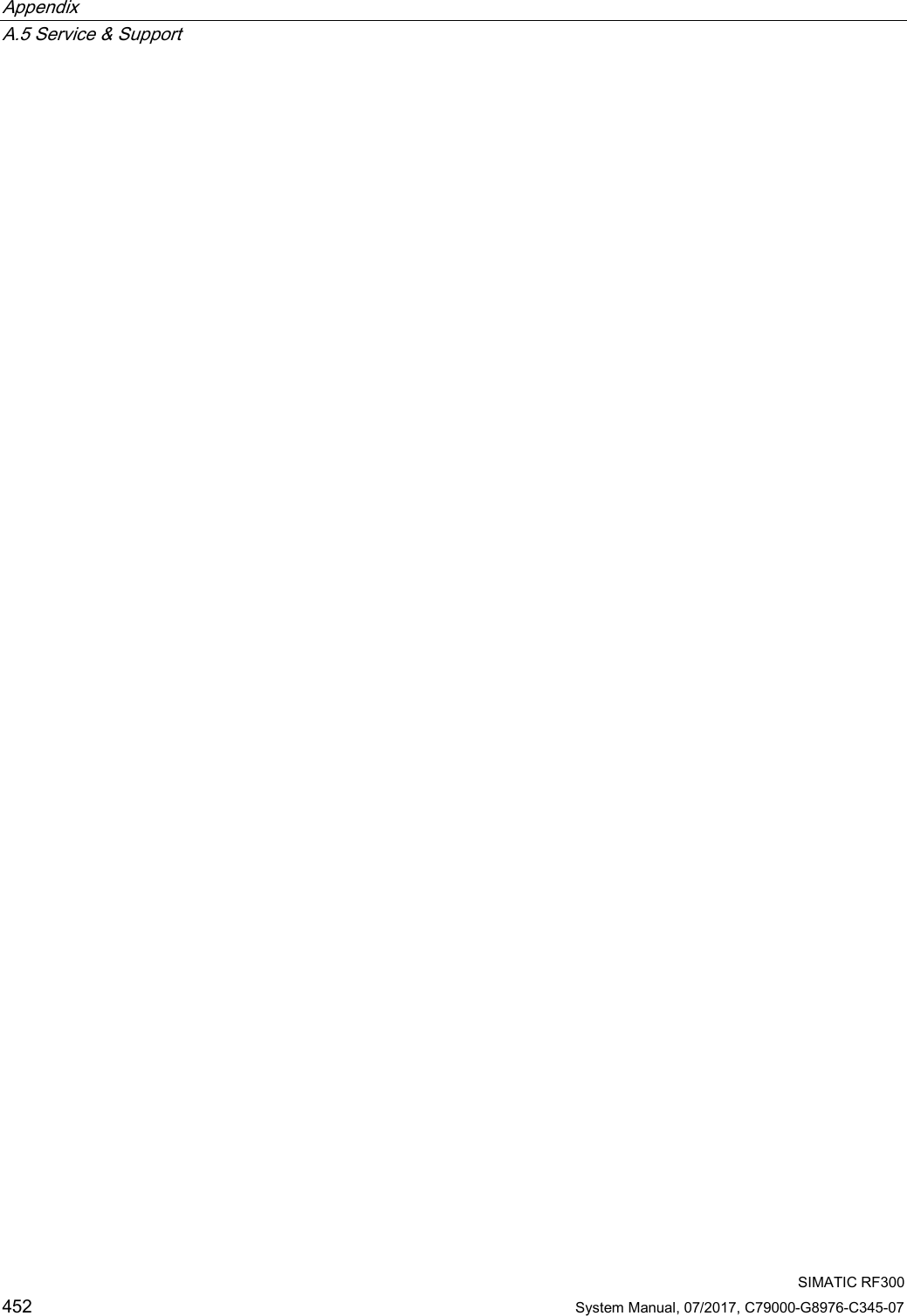
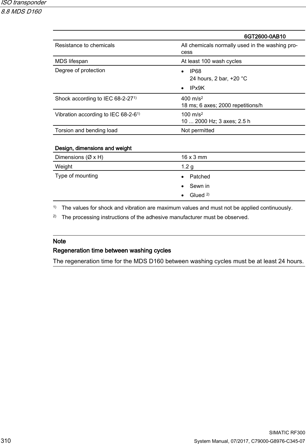
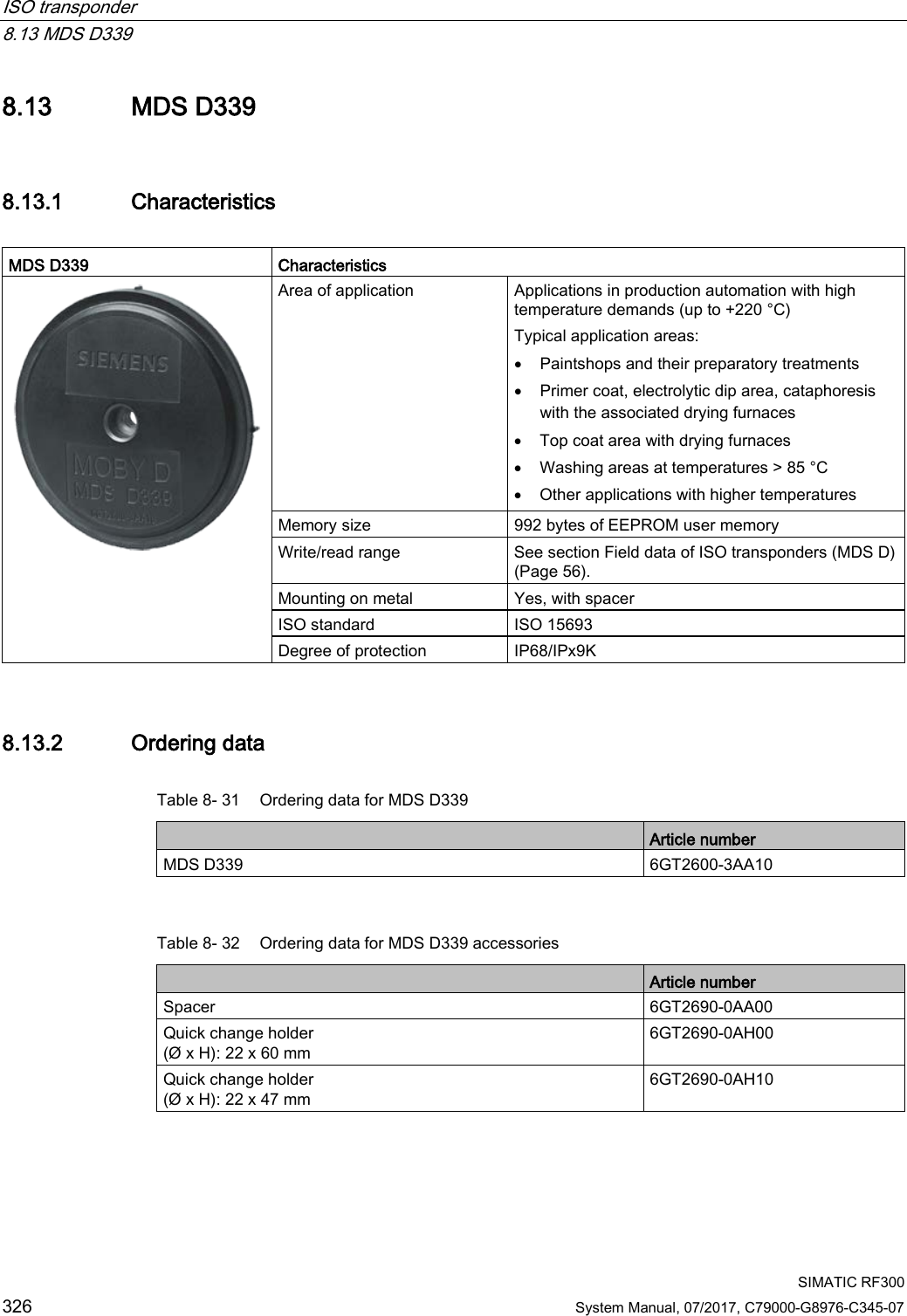
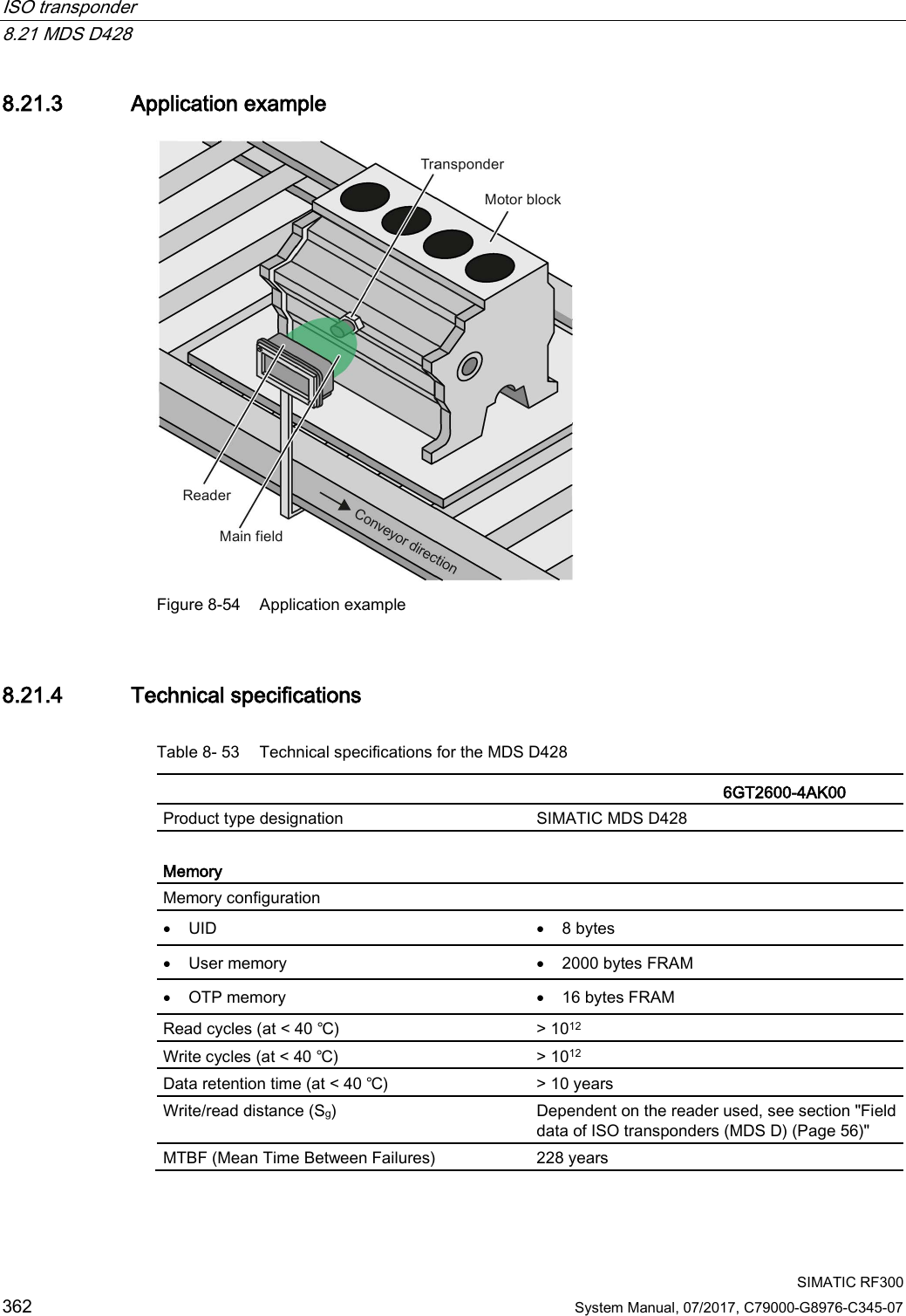
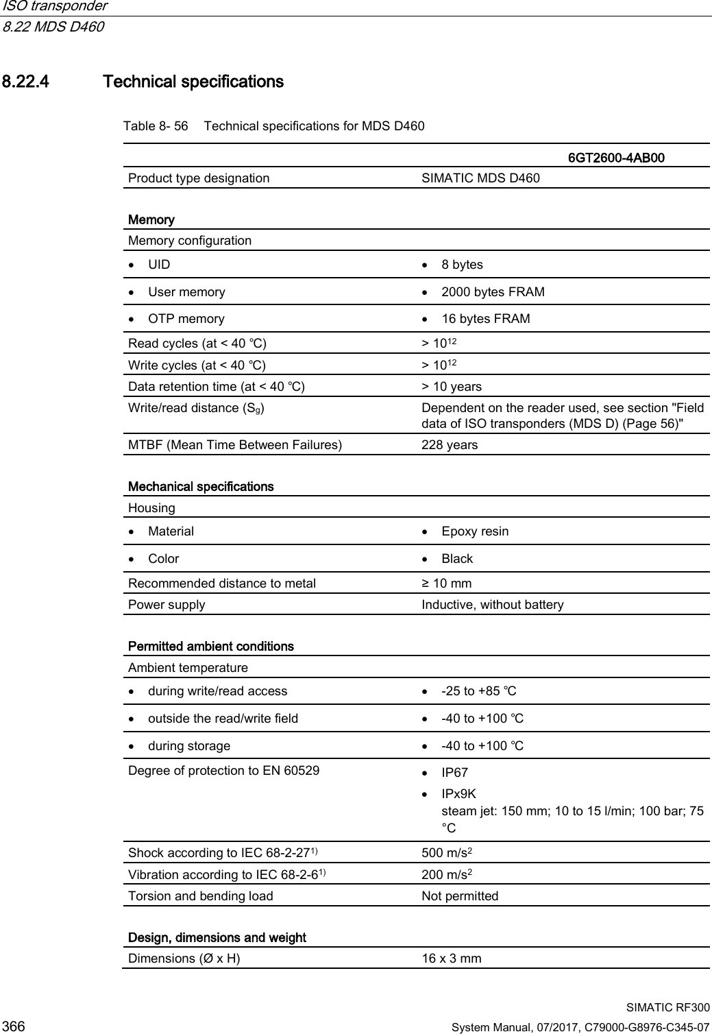
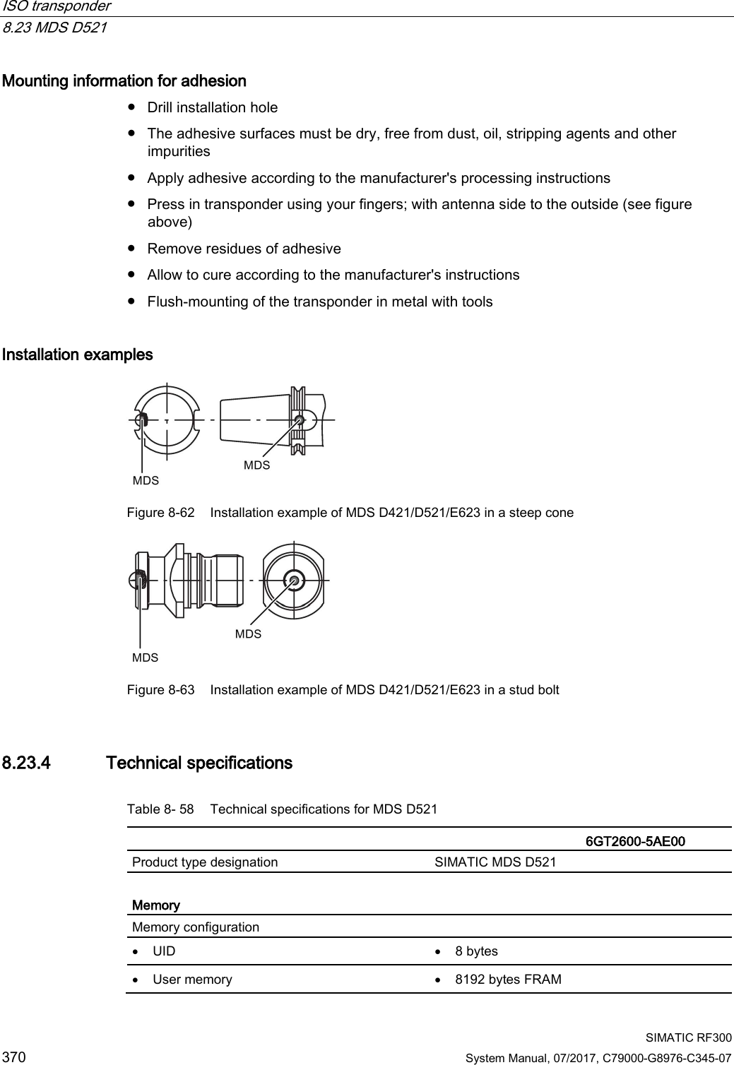
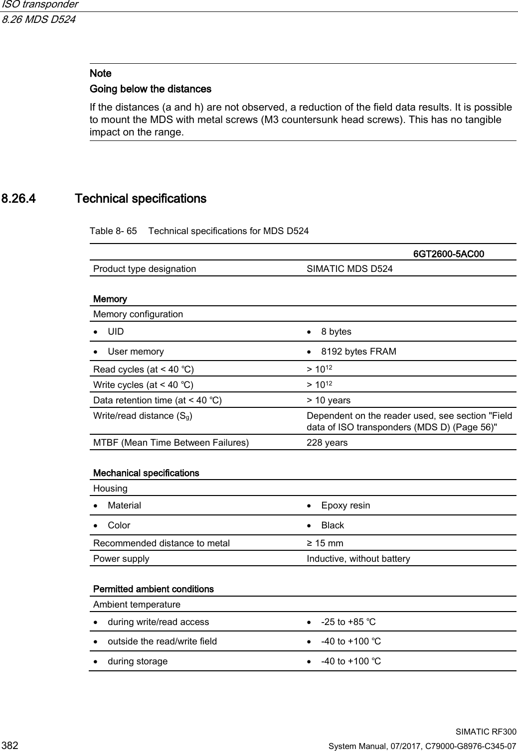
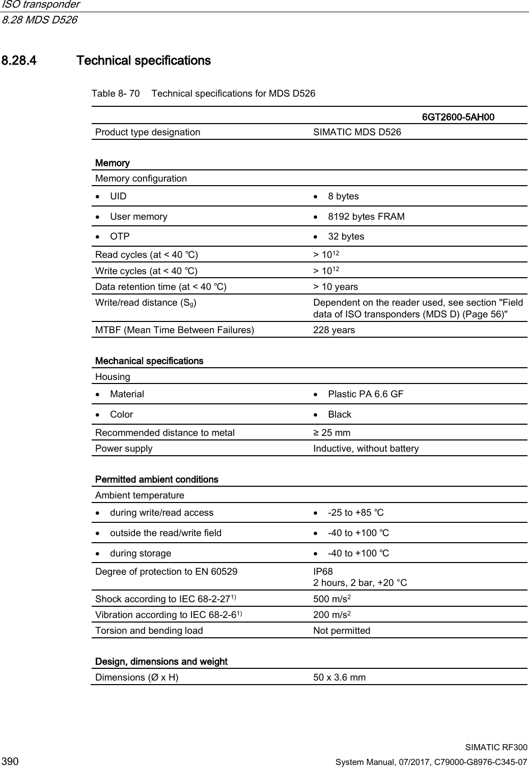
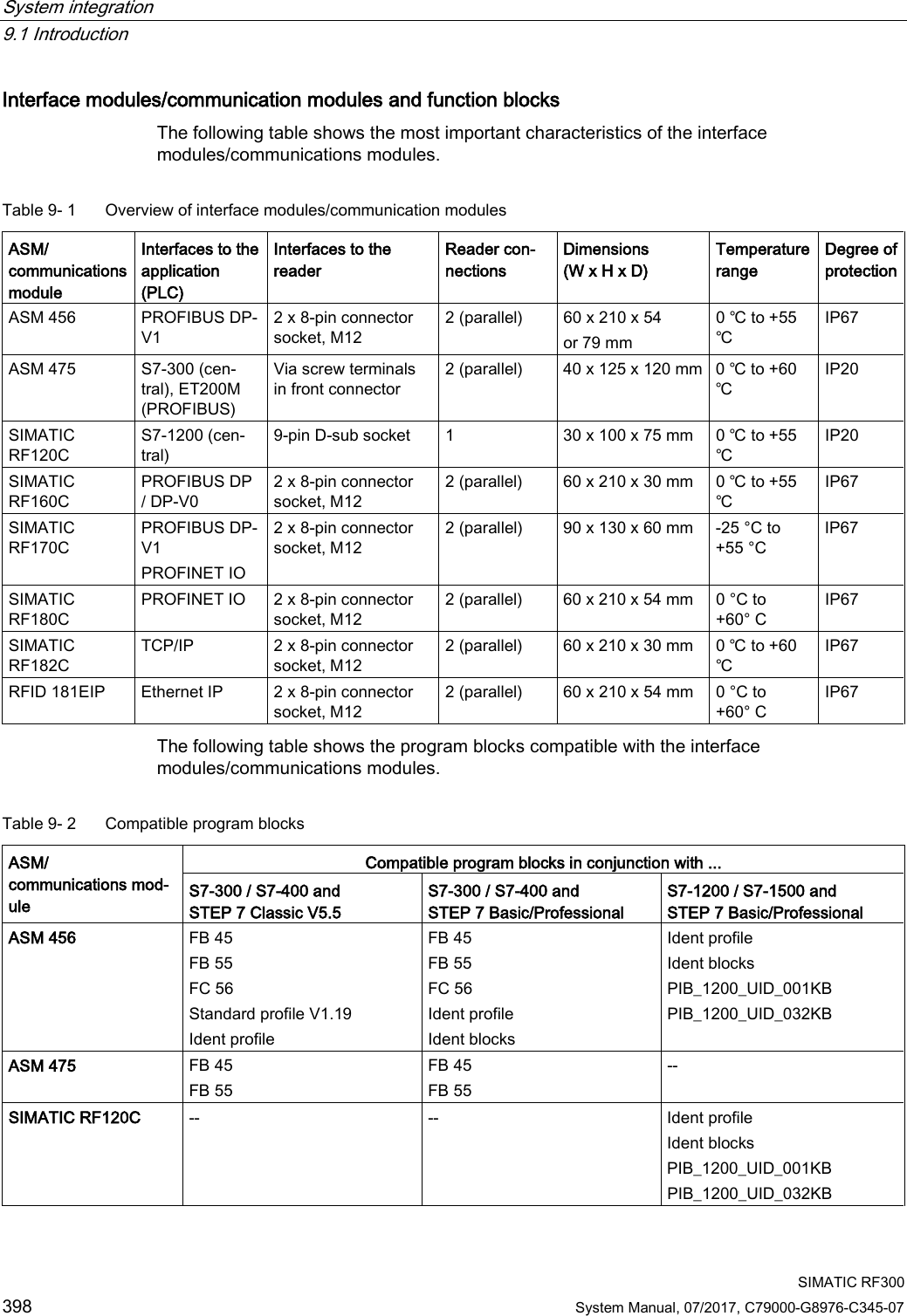
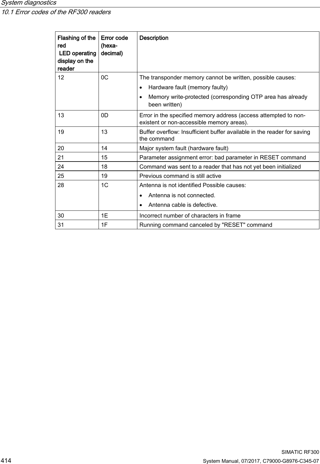
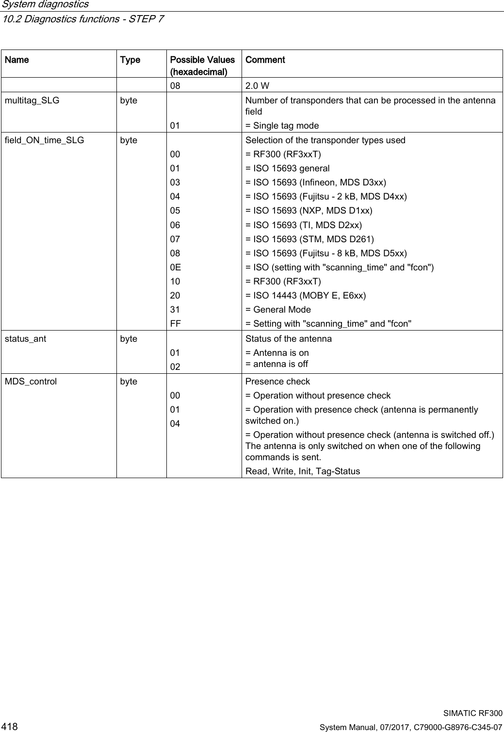
![System diagnostics 10.2 Diagnostics functions - STEP 7 SIMATIC RF300 System Manual, 07/2017, C79000-G8976-C345-07 421 Attribute "0x82" (mode 02), corresponds to UDT 270 (only for RF300 transponders) Name Type Possible Values (hex-adecimal) Comment UID array[1…8] byte 0000000055555555 ... 00000000FFFFFFFF Unique identifier = b0-31: 4 byte TAG ID, b32-63: 0 LFD byte 0 ... FF = Value for field strength determined in the transponder FZP byte 0 ... FF = Error counter (passive) ➙ errors during idle time FZA byte 0 ... FF = Error counter (active) ANWZ byte 0 ... FF = Presence counter Note Counter values are deleted. All counter values are deleted when the transponder exits the antenna field or when the antenna is switched off. Explanations: ● "LFD" is a measured value for the field strength that is determined in the transponder. The lower the value, the higher the field strength. ● "FZP" counts interference pulses when communication with a transponder is not taking place (e.g. electromagnetic interference caused by contactors, motors, etc.). Counter values can also be generated when a transponder is located at the edge of the field even when there is no external interference. ● "FZA" counts errors that can occur during reader-to-transponder communication. This can be caused by unsuitable reader/transponder positioning (e.g. transponder on field boundary, several data carriers in the field) or external electromagnetic interference. ● "ANWZ" is the value for the time that the transponder remains in the field before the "Tag-Status" (MDS STATUS) with attribute "0x82" (mode 02) is executed. A time step is 10 ms. The maximum time that can be recorded is therefore 2.5 s.](https://usermanual.wiki/Siemens/RF380R02.SYH-RF300-76-Part-3/User-Guide-3570477-Page-115.png)
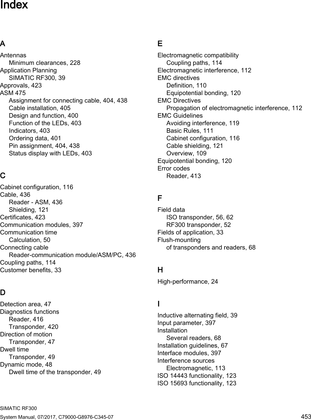
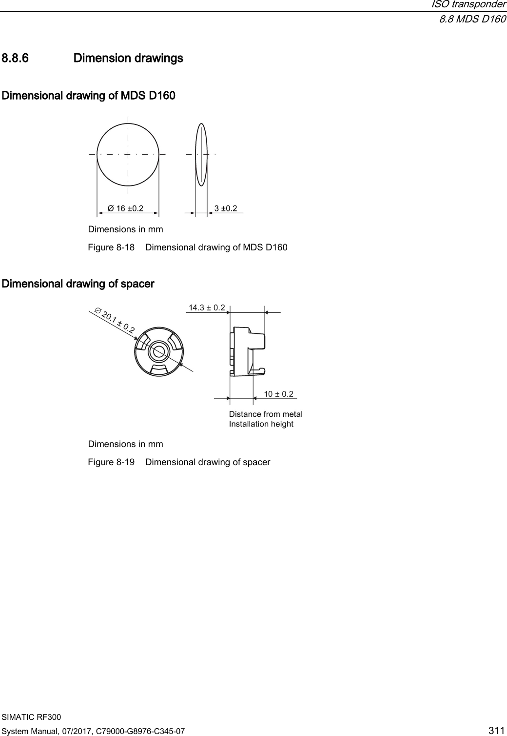
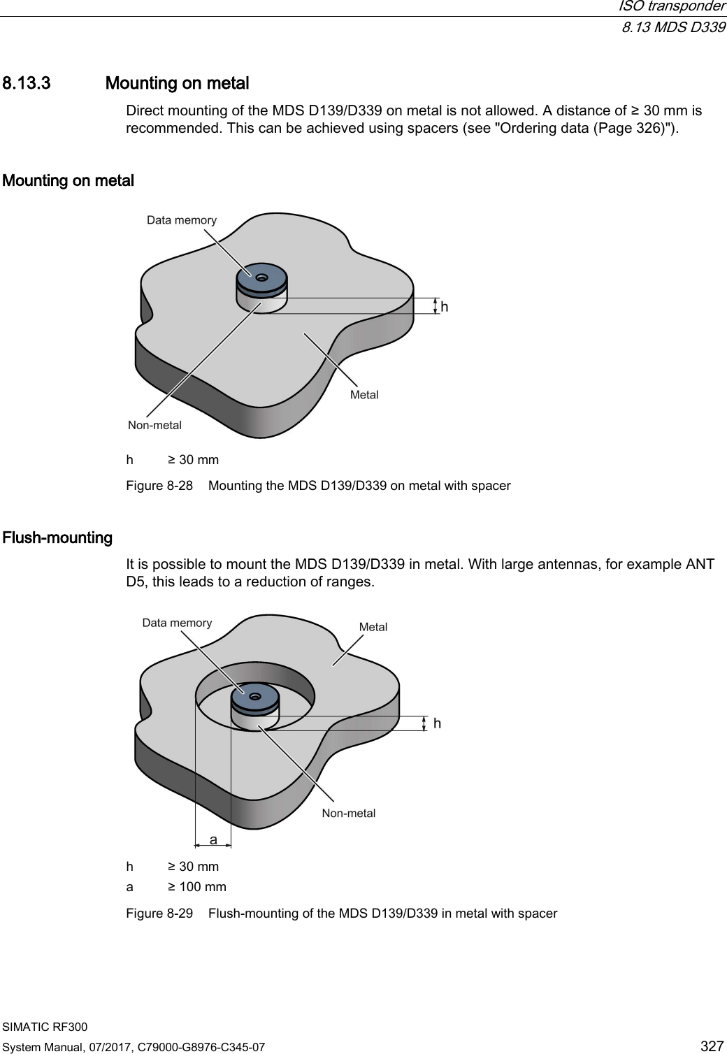
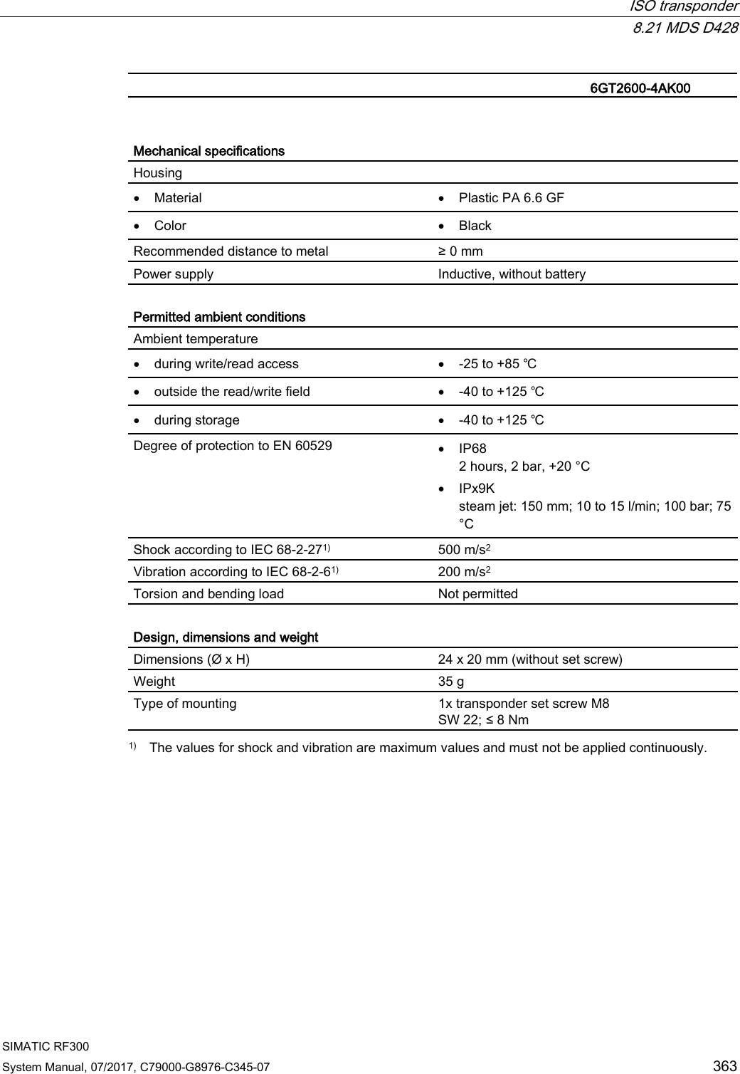
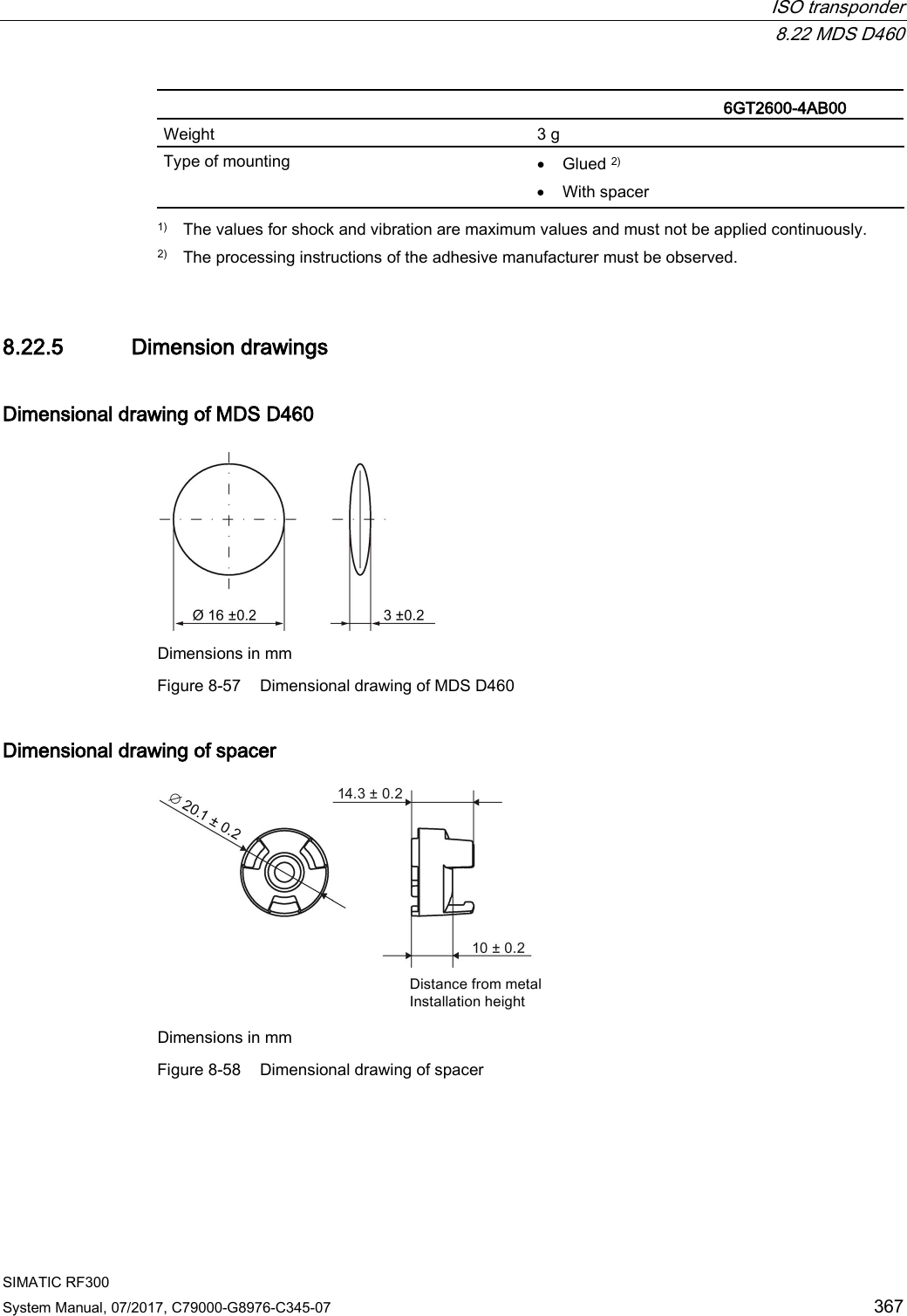
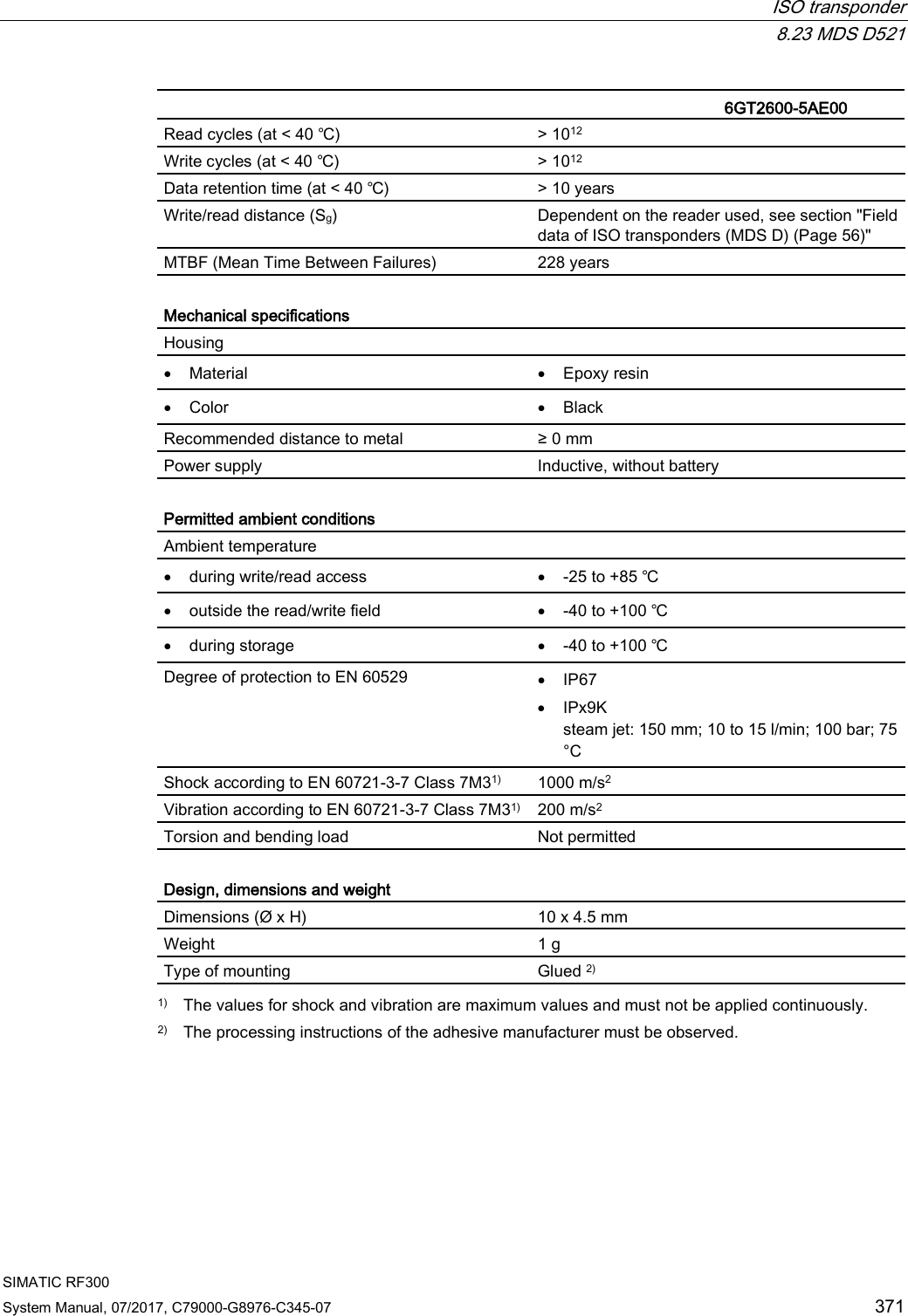
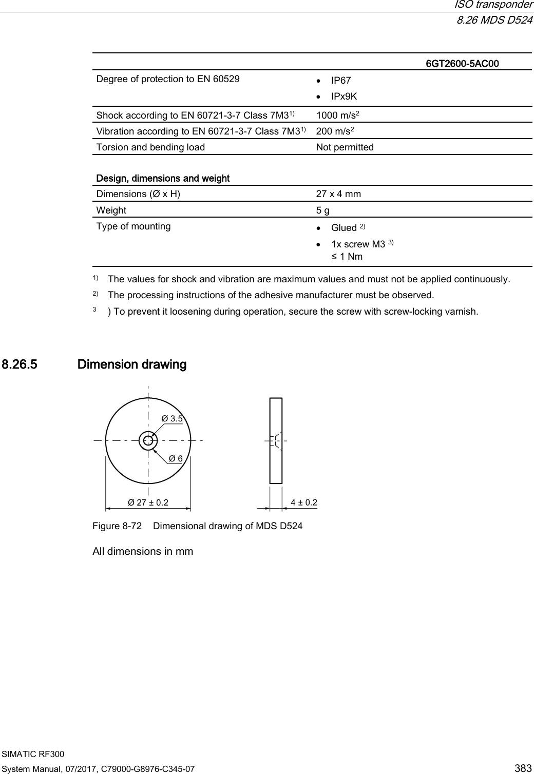
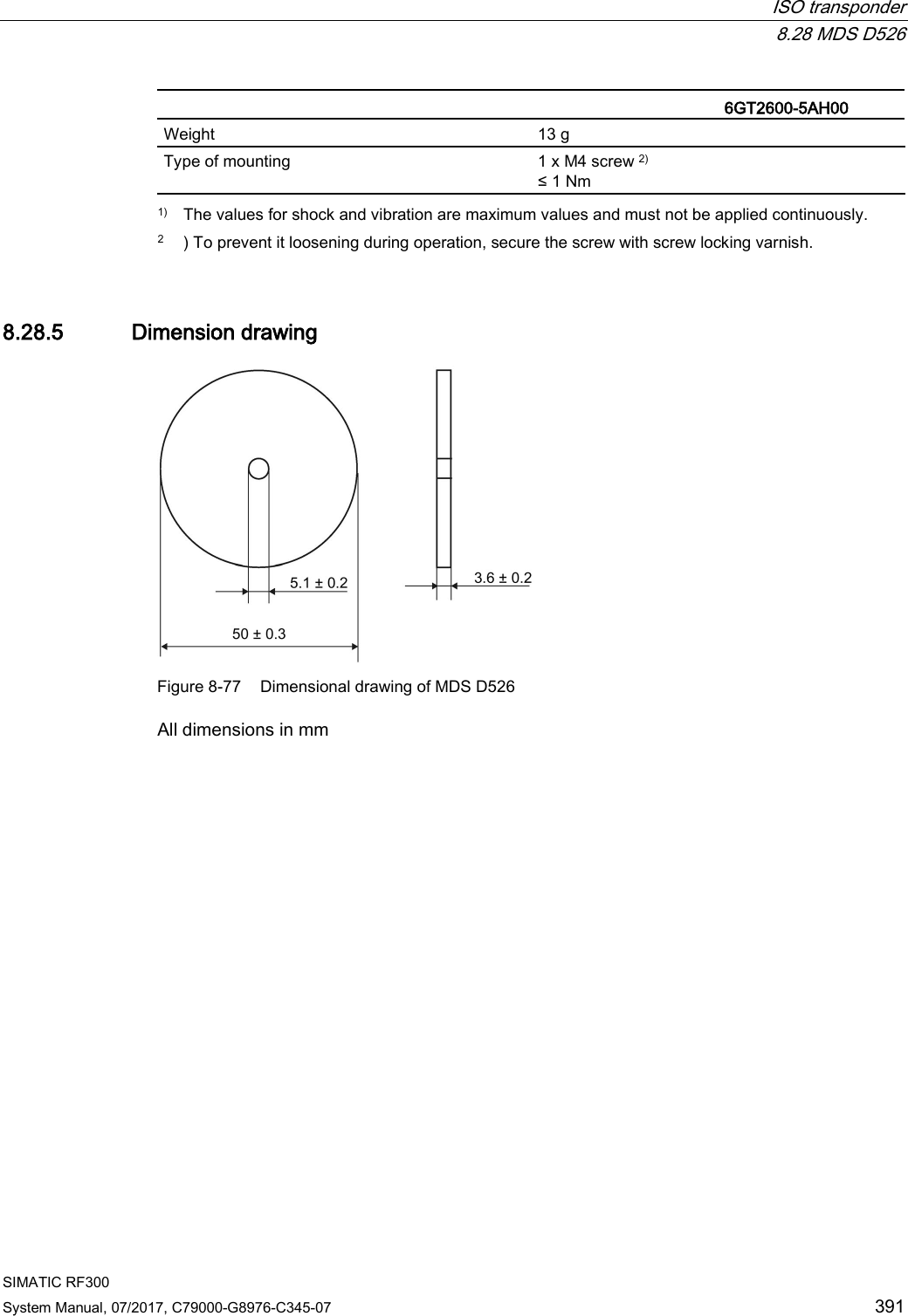
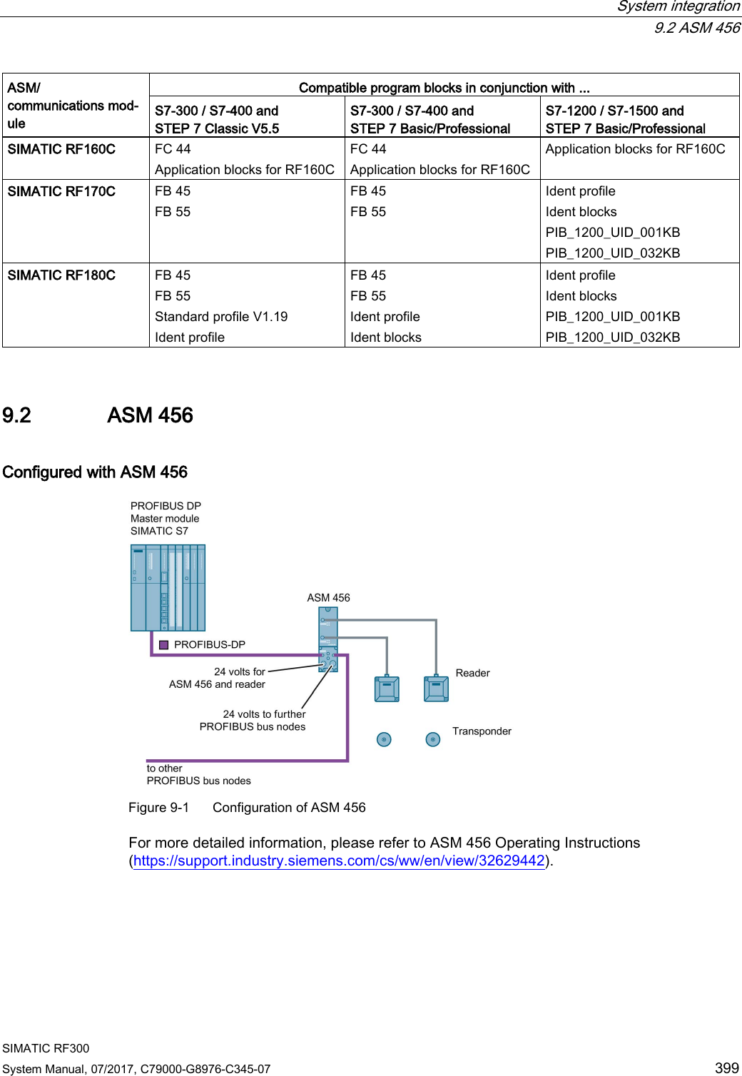
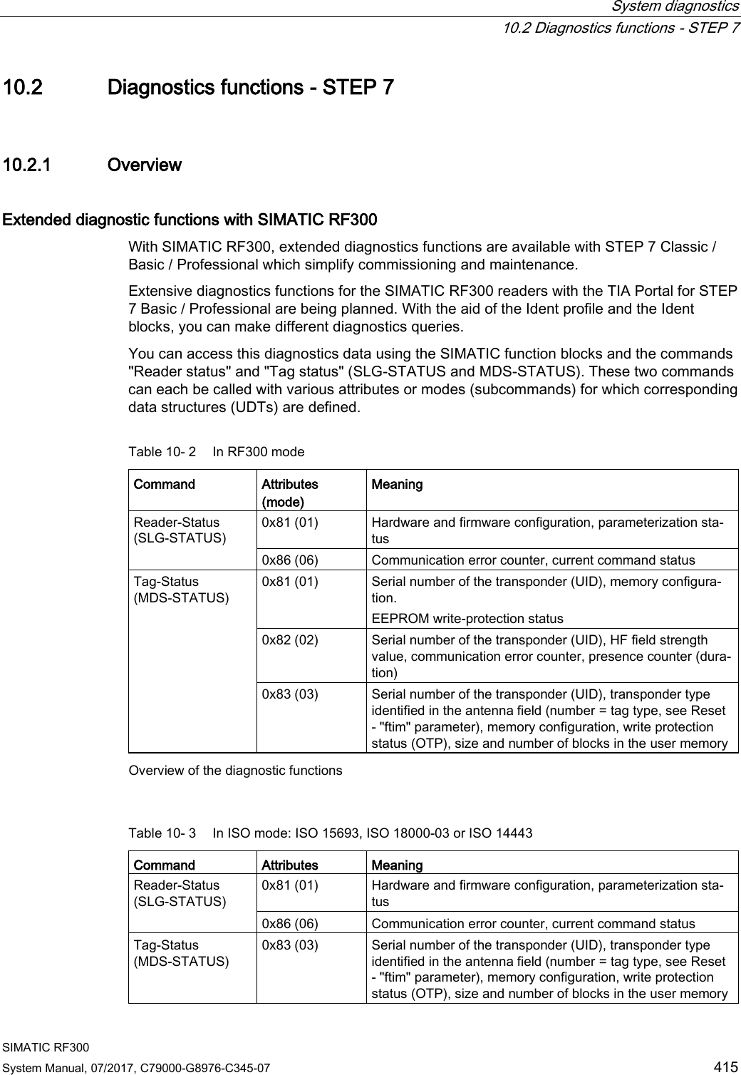
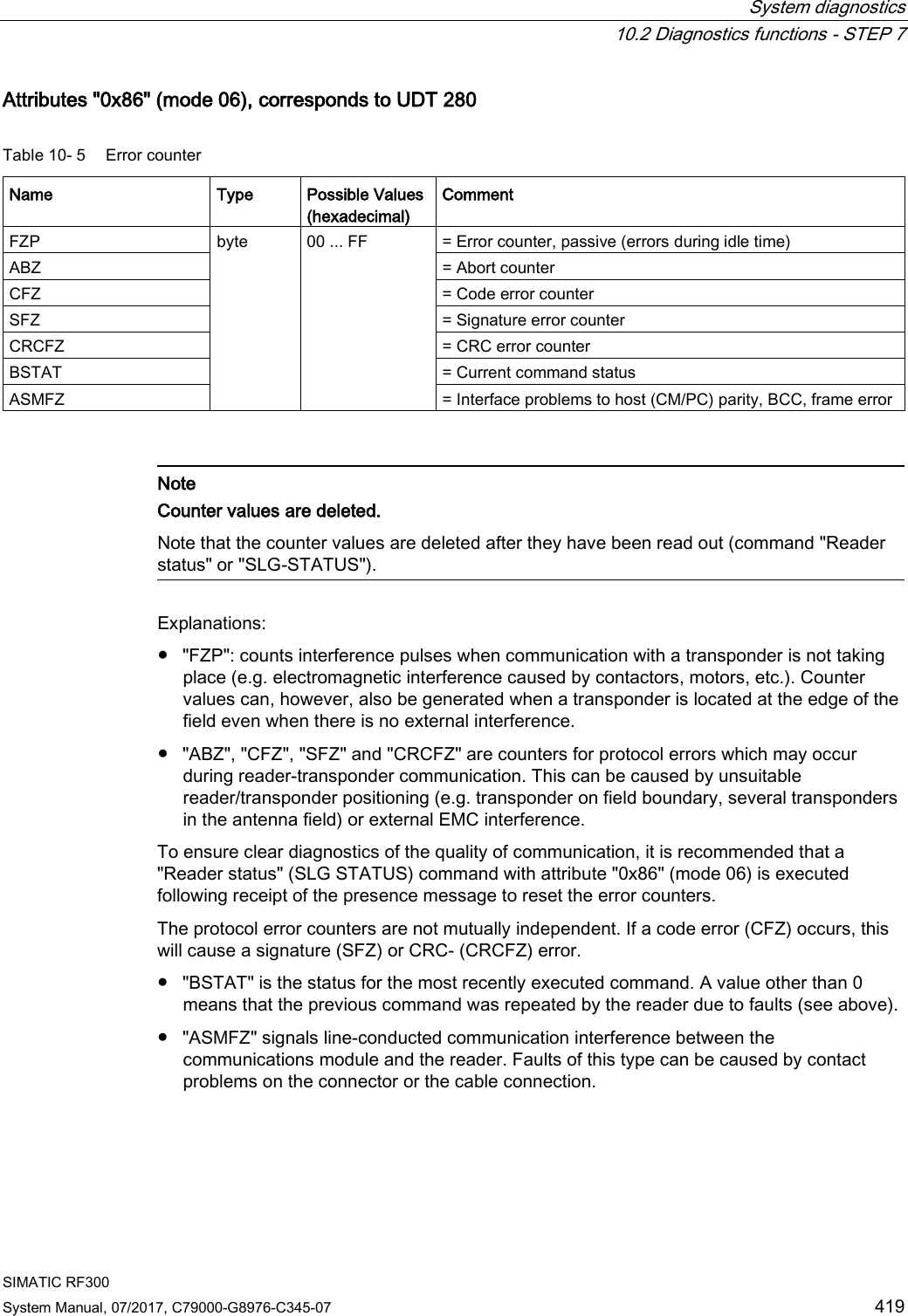
![System diagnostics 10.2 Diagnostics functions - STEP 7 SIMATIC RF300 422 System Manual, 07/2017, C79000-G8976-C345-07 Attribute "0x83" (mode 03), corresponds to UDT 230 Name Type Possible Values (hex-adecimal) Comment UID array[1…8] byte 0000000000000000 ... FFFFFFFFFFFFFFFF Unique identifier =8 byte UID, MSB first MDS_type byte 00 03 04 05 06 07 08 11 12 13 14 21 22 23 Transponder type (vendor, identification) = ISO 15693 general = ISO 15693 (Infineon, MDS D3xx) = ISO 15693 (Fujitsu - 2 kB, MDS D4xx) = ISO 15693 (NXP, MDS D1xx) = ISO 15693 (TI, MDS D200) = ISO 15693 (STM, MDS D261) = ISO 15693 (Fujitsu - 8 kB, MDS D5xx) = RF300 transponder (0 kB) = RF300 transponder (8 kB) = RF300 transponder (32 kB) = RF300 transponder (64 kB) = ISO 14443 (NXP, 1 kB, MDS E) = ISO 14443 (Infineon, 1 kB, MDS E) = ISO 14443 (NXP, 4 kB, MDS E) IC_version byte 0 ... FF Chip version size byte 0 ... FF Memory size in bytes depending on transponder type, e.g. MDS D3xx: 992 bytes lock_state byte 0 ... FF Lock state, OTP information: One bit is used per block (4 x 4 bytes or 2 x 8 bytes) (bit = 1: block is locked) Example: 01 = Block 1 of address FF80 ... FF83 is locked or 03 = Block 1 and 2 of address FF80 ... FF87 are locked, e.g. for the Philips SL2 ICS20 (MDS D124, D160 or D100). This chip provides a usable memory with 112 bytes EEPROM from address 0000 - 006F (total OTP area "0060 ... 006F"). In this memory, the locked area corre-sponds to the addresses 0060 ... 0063 or 0060 ... 0067 block_size byte 0 ... FF Block size of the transponder depending on transponder type, e.g. MDS D3xx: 4 bytes nr_of_blocks byte 0 ... FF Number of blocks depending on transponder type, e.g. MDS D3xx: 248 bytes](https://usermanual.wiki/Siemens/RF380R02.SYH-RF300-76-Part-3/User-Guide-3570477-Page-116.png)