Siemens RF380R02 RFID Reader 13.56 MHz User Manual SIMATIC RF300
Siemens AG RFID Reader 13.56 MHz SIMATIC RF300
Siemens >
Contents
- 1. SYH_RF300_76_Part 1
- 2. SYH_RF300_76_Part 2
- 3. SYH_RF300_76_Part 3
SYH_RF300_76_Part 3
ISO transponder
8.8 MDS D160
SIMATIC RF300
System Manual, 07/2017, C79000-G8976-C345-07 307
8.8
MDS D160
8.8.1
Characteristics
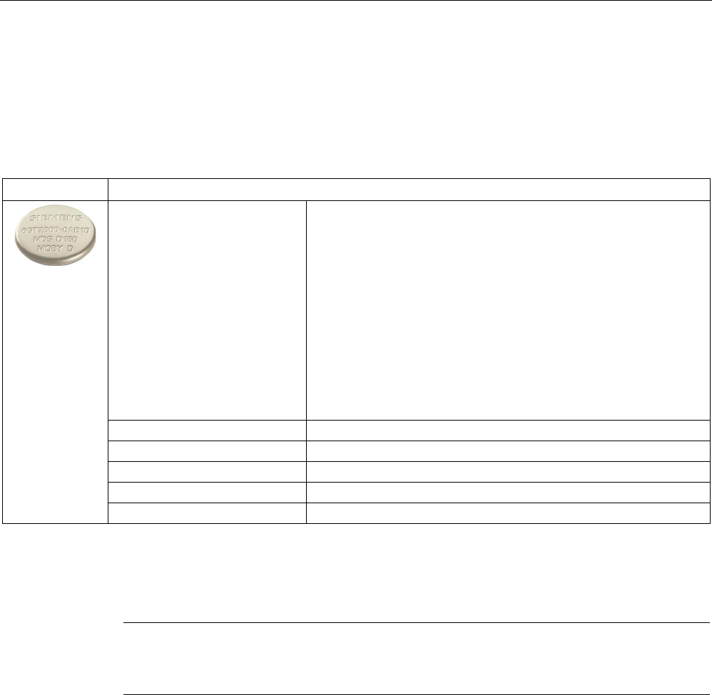
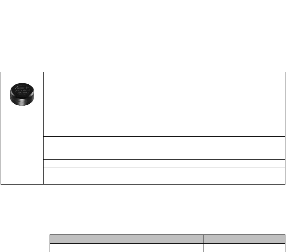
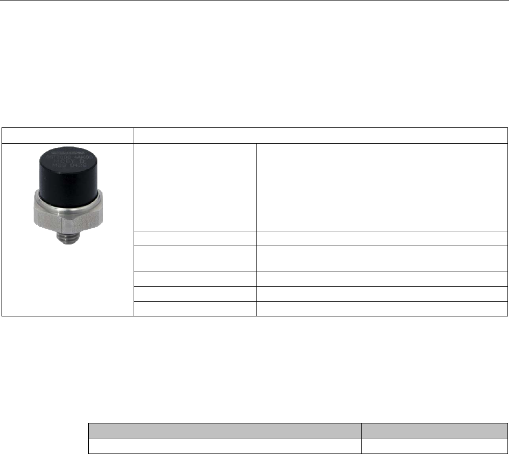
MDS D160
Characteristics
Area of application Thanks to its rugged packaging, the MDS D160 is a transponder that
can be used under extreme environmental conditions. It is washable,
heat-resistant and resistant to all chemicals generally used in the
laundry process.
Typical applications are, for example:
• Rented work clothing
• Hotel laundry
• Surgical textiles
• Hospital clothing
• Dirt collection mats
• Clothing for nursing homes/hostels
Memory size 112 bytes of EEPROM user memory
Write/read range
See section Field data of ISO transponders (MDS D) (Page 56).
Mounting on metal
Yes, with spacer
ISO standard
ISO 15693
Degree of protection
IP68/IPx9K
8.8.2
Information for RF300 compatibility
Note
Compatibility with SIMATIC RF300 depending on MLFB number
Only the MDS D160 with MLFB
6GT2600-0AB10 is compatible with SIMATIC RF300.
ISO transponder
8.8 MDS D160
SIMATIC RF300
308 System Manual, 07/2017, C79000-G8976-C345-07
8.8.3
Ordering data
Table 8- 18 Ordering data for MDS D160
Article number
MDS D160
6GT2600-0AB10
Table 8- 19 Ordering data for MDS D160 accessories
Article number
Spacer
6GT2690-0AG00
8.8.4
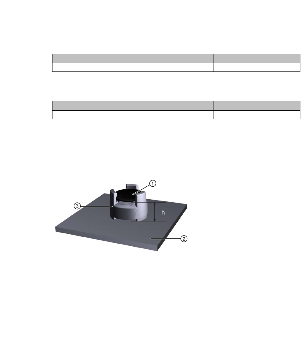
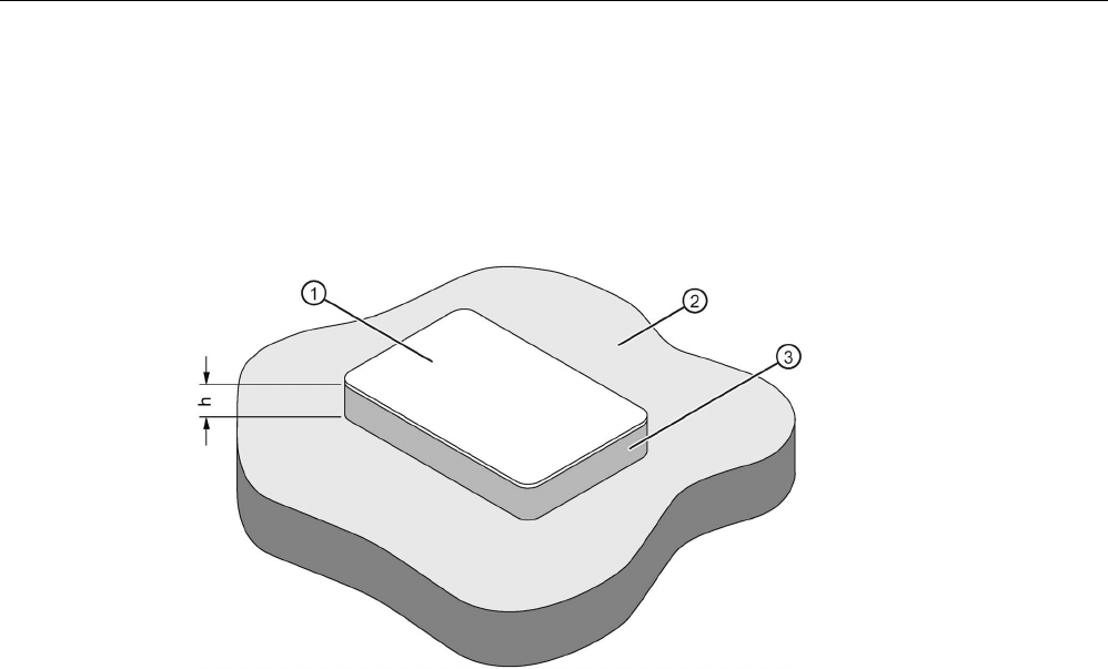
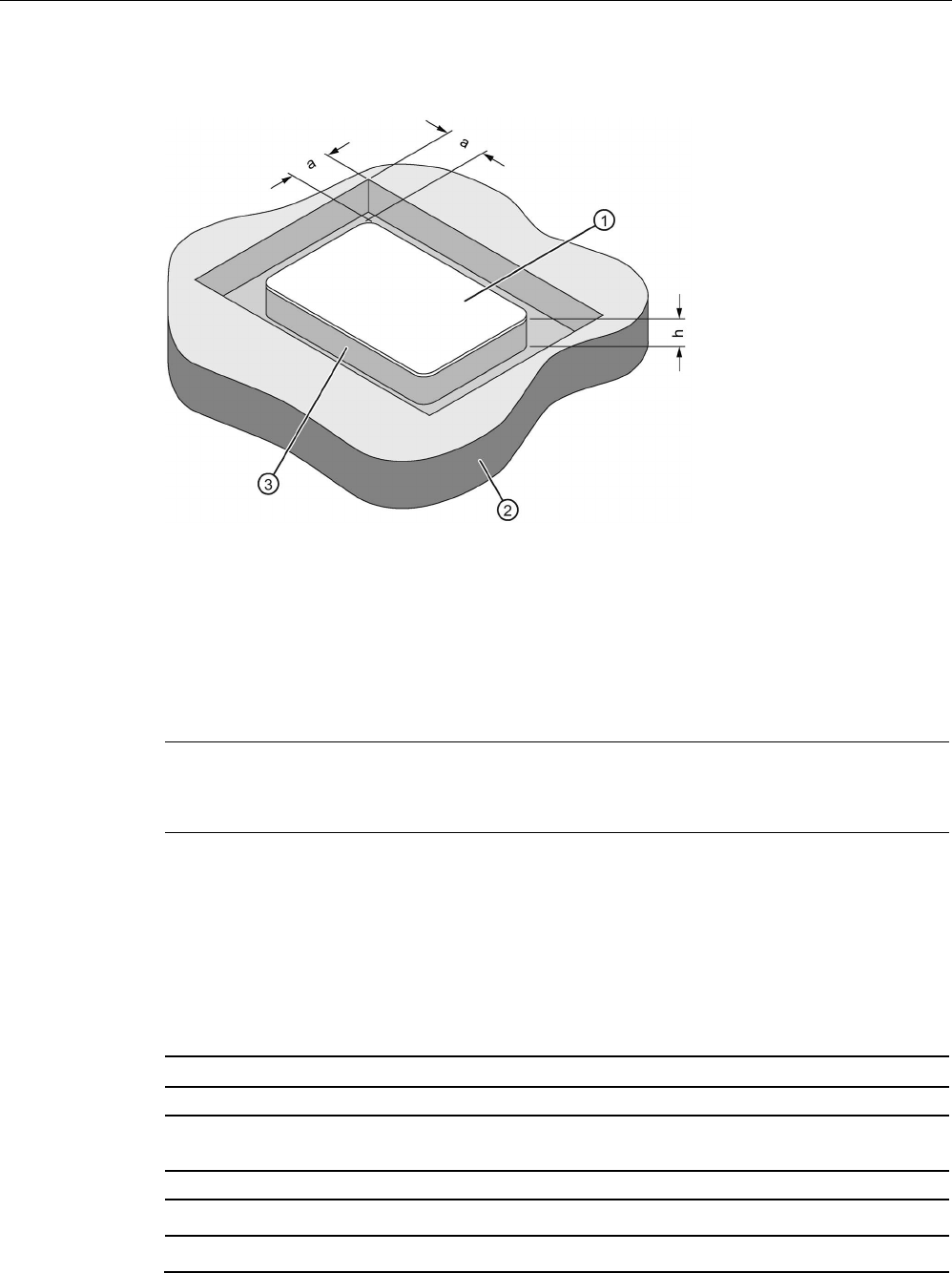
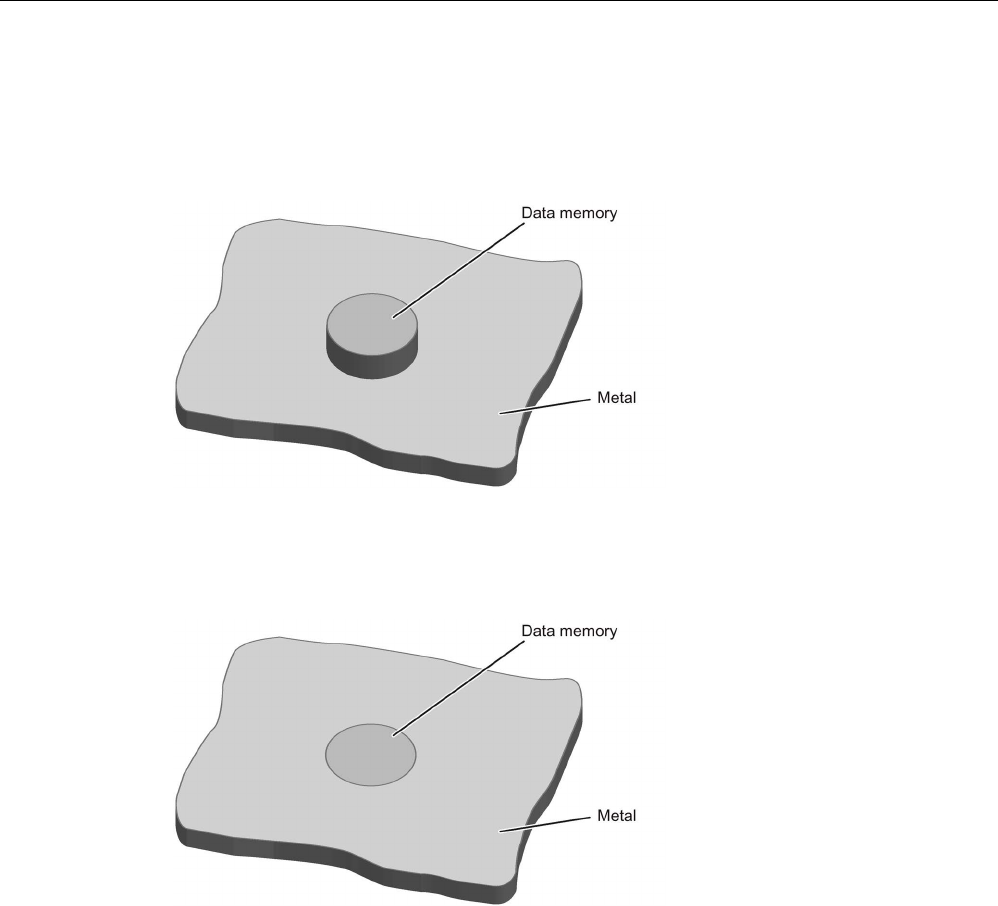
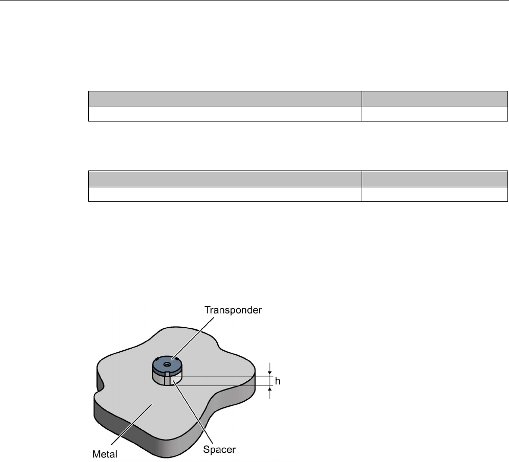
Mounting on metal
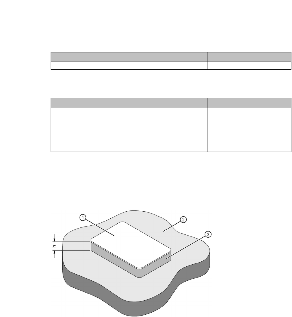
Mounting on metal
①
Transponder
②
Metal carrier
③
Spacer
h
≥ 10 mm
Figure 8-17 Mounting the MDS D160 on metal with spacer
Note
Going below the minimum distance (h)
If the minimum distance (h) is not observed, a reduction of the fie
ld data results.
In critical applications, it is recommended that a test is performed.
Flush-mounting
Flush-mounting of the MDS D160 in metal is not permitted!

ISO transponder
8.8 MDS D160
SIMATIC RF300
System Manual, 07/2017, C79000-G8976-C345-07 309
8.8.5
Technical specifications
Table 8- 20 Technical specifications for the MDS D160
6GT2600-0AB10
Product type designation
SIMATIC MDS D160
Memory
Memory configuration
• UID • 8 bytes
• User memory • 112 bytes EEPROM
• OTP memory • 16 bytes (EEPROM)
Read cycles (at < 40 ℃)
> 10
14
Write cycles (at < 40 ℃)
> 10
6
Data retention time (at < 40 ℃)
> 10 years
Write/read distance (Sg) Dependent on the reader used, see section "Field
data of ISO transponders (MDS D) (Page 56)"
MTBF (Mean Time Between Failures)
228 years
Mechanical specifications
Housing
• Material
• Color
• PPS
• beige
Recommended distance to metal
≥ 10 mm
Power supply
Inductive, without battery
Permitted ambient conditions
Ambient temperature
• during write/read access
• -25 … +85 °C
• outside the read/write field • -40 … +175 °C
• from +125 ℃: for 1000 hours, 20% reduction
of the limit distance
• at +175 ℃: 100 washing cycles tested
• at +220 ℃: Tested once for up to 30 seconds
• during storage • -25 to +100 ℃
Mechanical strength
• Isostatic pressure • 300 bar for 5 min
• Axial pressure • 1000 N for 10 s
• Radial pressure • 1000 N for 10 s

ISO transponder
8.8 MDS D160
SIMATIC RF300
310 System Manual, 07/2017, C79000-G8976-C345-07
6GT2600-0AB10
Resistance to chemicals All chemicals normally used in the washing pro-
cess
MDS lifespan
At least 100 wash cycles
Degree of protection • IP68
24 hours, 2 bar, +20 °C
• IPx9K
Shock according to IEC 68-2-271) 400 m/s2
18 ms; 6 axes; 2000 repetitions/h
Vibration according to IEC 68-2-61) 100 m/s2
10 ... 2000 Hz; 3 axes; 2.5 h
Torsion and bending load
Not permitted
Design, dimensions and weight
Dimensions (Ø x H)
16 x 3 mm
Weight
1.2 g
Type of mounting • Patched
• Sewn in
• Glued 2)
1)
The values for shock and vibration are maximum values and must not be applied continuously.
2) The processing instructions of the adhesive manufacturer must be observed.
Note
Regeneration time between washing cycles
The regeneration time for the MDS D160 between washing cycles must be at lea
st 24 hours.
ISO transponder
8.8 MDS D160
SIMATIC RF300
System Manual, 07/2017, C79000-G8976-C345-07 311
8.8.6
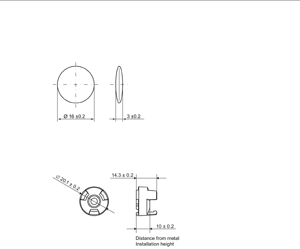
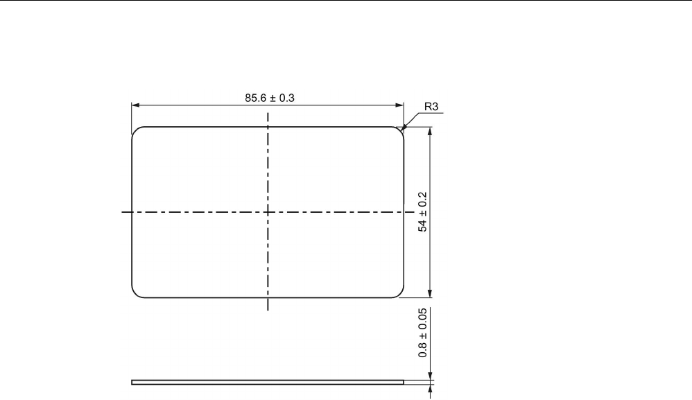
Dimension drawings
Dimensional drawing of MDS D160
Dimensions in mm
Figure 8-18 Dimensional drawing of MDS D160
Dimensional drawing of spacer
Dimensions in mm
Figure 8-19 Dimensional drawing of spacer

ISO transponder
8.9 MDS D165
SIMATIC RF300
312 System Manual, 07/2017, C79000-G8976-C345-07
8.9
MDS D165
8.9.1
Features
MDS D165 (special version)
Characteristics
Area of application The design of the transponder (self-adhesive label)
permits a variety of designs, guaranteeing optimum
dimensioning for the widest variety of applications.
From simple identification such as electronic barcode
replacement/supplementation, through warehouse
and distribution logistics, right up to product identifi-
cation.
Memory size
112 bytes of EEPROM user memory
Write/read range See section Field data of ISO transponders (MDS D)
(Page 56).
Mounting on metal
Yes, with spacer
ISO standard
ISO 15693
Degree of protection
IP65
8.9.2
Ordering data
Table 8- 21 Ordering data for MDS D165
Article number
MDS D165 (special version ISO-CARD)
6GT2600-1AB00-0AX0
Type of delivery
Minimum order quantity: 1250 units (5 rolls with 250 units each)
8.9.3
Technical data
Table 8- 22 Technical specifications for MDS D165
6GT2600-1AB00-0AX0
Product type designation
SIMATIC MDS D165
Memory
Memory configuration
• UID • 8 bytes

ISO transponder
8.9 MDS D165
SIMATIC RF300
System Manual, 07/2017, C79000-G8976-C345-07 313
6GT2600-1AB00-0AX0
• User memory • 112 bytes EEPROM
• OTP memory • 16 bytes (EEPROM)
Read cycles (at < 40 ℃)
> 10
14
Write cycles (at < 40 ℃)
> 10
6
Data retention time (at < 40 ℃)
> 10 years
Write/read distance (Sg) Dependent on the reader used, see section "Field
data of ISO transponders (MDS D) (Page 56)"
MTBF (Mean Time Between Failures)
228 years
Mechanical specifications
Housing
• Material • Top • PET plastic (label
material)
• Inlay • PET plastic (carrier
material)
• Antenna • Aluminum
• Bottom • Double-sided trans-
fer adhesive on sili-
con paper
• Color • White
Recommended distance to metal
≥ 25 mm
Power supply
Inductive, without battery
Permitted ambient conditions
Ambient temperature
• during write/read access • -25 ... +80 °C
• outside the read/write field • -25 to +80 ℃
• during storage • +20 to +30 ℃
Can be stored for 2 years, determined by the
durability of the adhesive.
Degree of protection
IP65
Design, dimensions and weight
Dimensions (L x W x H)
86 x 54 x 0.3 mm
Weight 1 g
Type of mounting Glued with self-adhesive label 1)
1) The processing instructions of the adhesive manufacturer must be observed.
ISO transponder
8.10 MDS D200
SIMATIC RF300
314 System Manual, 07/2017, C79000-G8976-C345-07
8.9.4
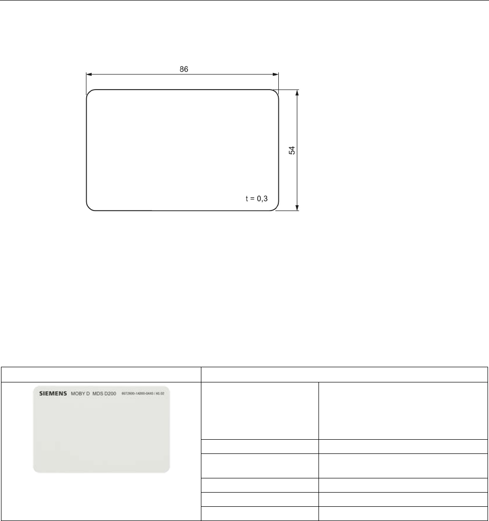
Dimension drawing
Dimensions in mm
Figure 8-20 Dimension drawing of MDS D165
8.10
MDS D200
8.10.1
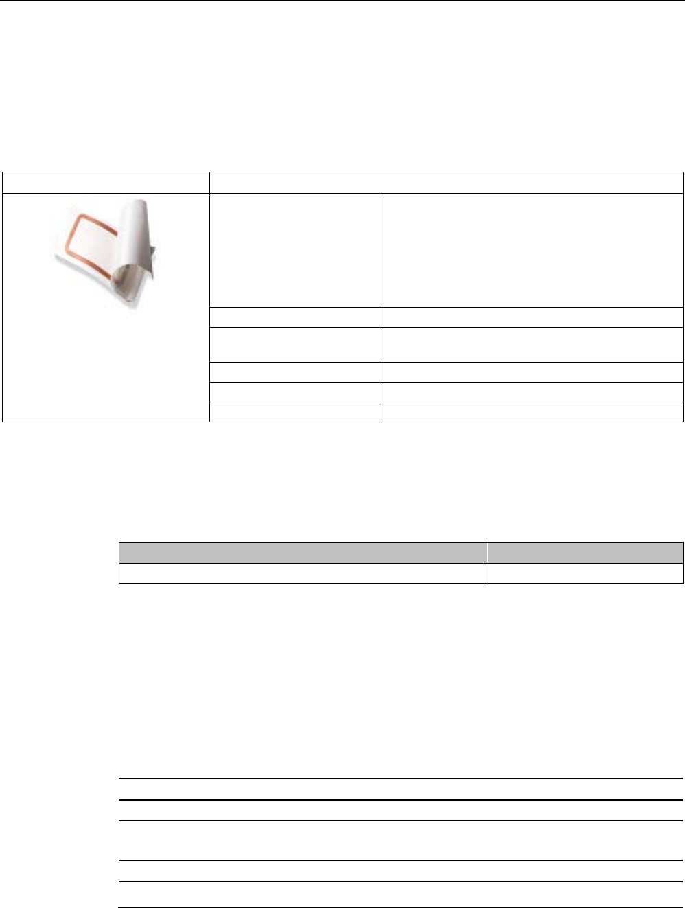
Features
MDS D200
Characteristics
Area of application From simple identification such as elec-
tronic barcode replace-
ment/supplementation, through
warehouse and distribution logistics, right
up to product identification.
Memory size
256 bytes of EEPROM user memory
Write/read range See section Field data of ISO transpond-
ers (MDS D) (Page 56).
Mounting on metal
Yes, with spacer
ISO standard
15693 with Tag-it HFI technology
Degree of protection
IP67
ISO transponder
8.10 MDS D200
SIMATIC RF300
System Manual, 07/2017, C79000-G8976-C345-07 315
8.10.2
Ordering data
Table 8- 23 Ordering data for MDS D200
Article number
MDS D200 (special version ISO-CARD)
6GT2600-1AD00-0AX0
Table 8- 24 Ordering data for MDS D200 accessories
Article number
Spacer
(in conjunction with fixing pocket 6GT2190-0AB00)
6GT2190-0AA00
Fixing pocket
(in conjunction with spacer 6GT2190-0AA00)
6GT2190-0AB00
Fixing pocket
(not suitable for fixing directly onto metal)
6GT2390-0AA00
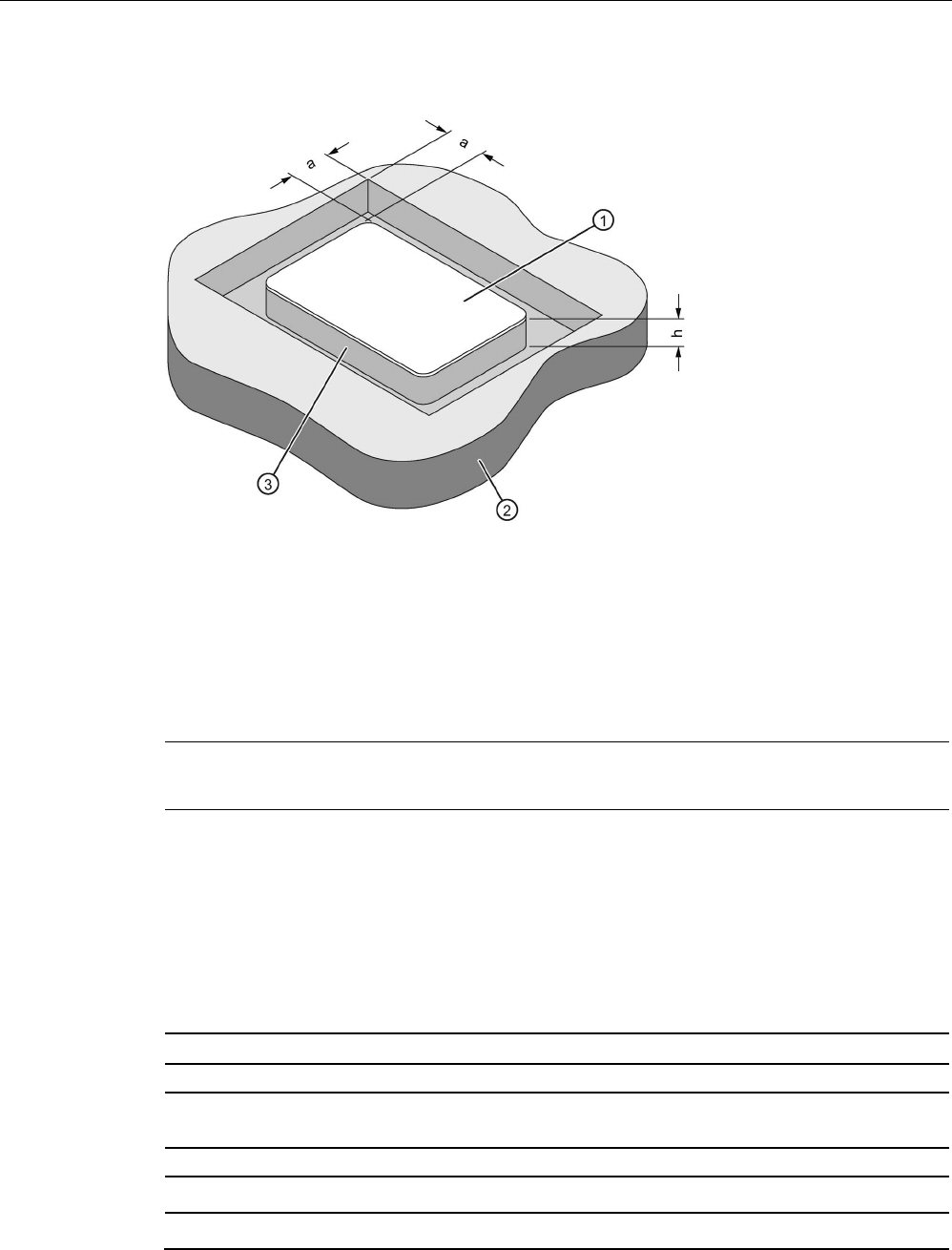
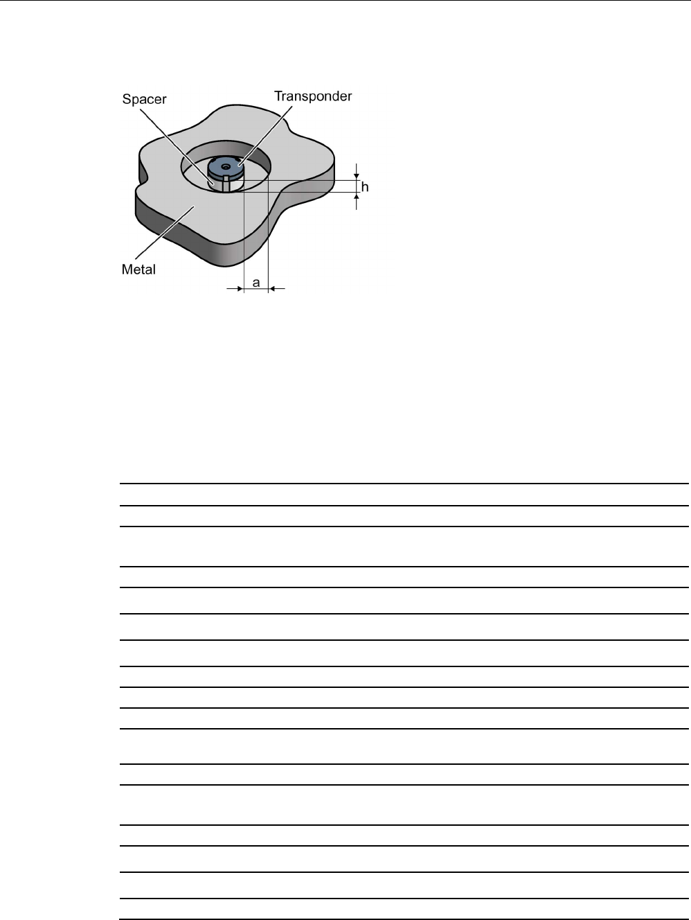
8.10.3
Mounting on metal
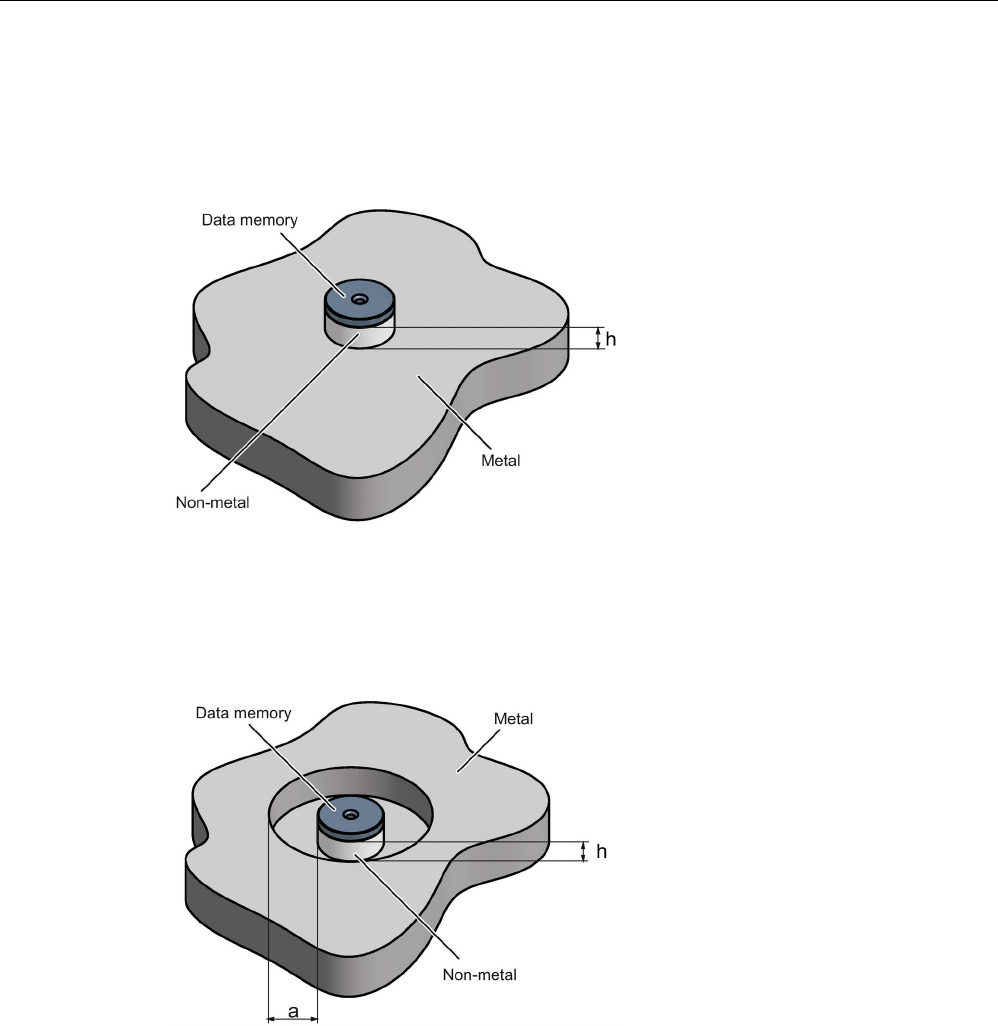
Mounting on metal
h
≥ 20 mm
①
Transponder
②
Metal
③
Non-metal
Figure 8-21 Mounting of the MDS D200 on metal with spacer
ISO transponder
8.10 MDS D200
SIMATIC RF300
316 System Manual, 07/2017, C79000-G8976-C345-07
Flush-mounting
a
≥ 20 mm
h
≥ 20 mm
①
Transponder
②
Metal
③
Non-metal
Figure 8-22 Flush-mounting of MDS D200 in metal with spacer
Note
If the minimum guide values (h) are not observed, a reductio
n of the field data results.
8.10.4
Technical data
Table 8- 25 Technical specifications for MDS D200
6GT2600-1AD00-0AX0
Product type designation
SIMATIC MDS D200
Memory
Memory configuration
• UID • 8 bytes
• User memory • 256 bytes EEPROM

ISO transponder
8.10 MDS D200
SIMATIC RF300
System Manual, 07/2017, C79000-G8976-C345-07 317
6GT2600-1AD00-0AX0
• OTP memory • 16 bytes (EEPROM)
Read cycles (at < 25 ℃)
> 10
14
Write cycles (at < 25 ℃)
> 10
6
Data retention time (at < 25 ℃)
> 10 years
Write/read distance (Sg) Dependent on the reader used, see section "Field
data of ISO transponders (MDS D) (Page 56)"
MTBF (Mean Time Between Failures)
228 years
Mechanical specifications
Housing
• Material • PET
• Color • White
Recommended distance to metal
≥ 20 mm
Power supply
Inductive, without battery
Permitted ambient conditions
Ambient temperature
• during write/read access • -20 to +60 ℃
• outside the read/write field • -20 to +60 ℃
• during storage • -20 to +60 ℃
Degree of protection to EN 60529
IP67
Shock-resistant to EN 60721-3-7 class 7M3
ISO 10373 / ISO 7810
1)
Vibration-resistant to EN 60721-3-7, class 7M3
ISO 10373 / ISO 7810
1)
Torsion and bending load
ISO 10373/ISO 7816-1
Design, dimensions and weight
Dimensions (L x W x H)
85 x 54 x 0.8 mm
Weight
5 g
Type of mounting • Fixing pocket
• Glued 2)
1
) The values for shock and vibration are maximum values and must not be applied continuously.
2) The processing instructions of the adhesive manufacturer must be observed.
ISO transponder
8.11 MDS D261
SIMATIC RF300
318 System Manual, 07/2017, C79000-G8976-C345-07
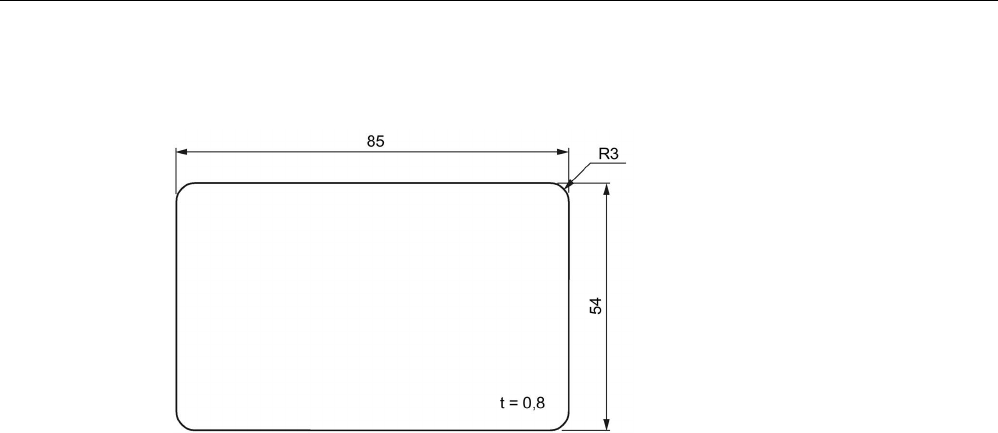
8.10.5
Dimension drawing
Dimensions in mm
Figure 8-23 Dimension drawing of MDS D200
ISO transponder
8.11 MDS D261
SIMATIC RF300
System Manual, 07/2017, C79000-G8976-C345-07 319
8.11
MDS D261
8.11.1
Features
MDS D261
Characteristics
Area of application The design of the transponder (self-adhesive label)
permits a variety of designs, guaranteeing optimum
dimensioning for the widest variety of applications.
From simple identification such as electronic barcode
replacement/supplementation, through warehouse
and distribution logistics, right up to product identifi-
cation.
Memory size
256 bytes of EEPROM user memory
Write/read range See section Field data of ISO transponders (MDS D)
(Page 56).
Mounting on metal
Yes, with spacer
ISO standard
ISO 15693
Degree of protection
IP65
8.11.2
Ordering data
Table 8- 26 Ordering data for MDS D261
Article number
MDS D261
6GT2600-1AA00-0AX0
Type of delivery
Minimum order quantity: 1250 units (5 rolls with 250 units each)
8.11.3
Technical data
Table 8- 27 Technical specifications of MDS D261
6GT2600-1AA01-0AX0
Product type designation
SIMATIC MDS D261
Memory
Memory configuration
• UID • 8 bytes

ISO transponder
8.11 MDS D261
SIMATIC RF300
320 System Manual, 07/2017, C79000-G8976-C345-07
6GT2600-1AA01-0AX0
• User memory • 256 bytes EEPROM
• OTP memory • 16 bytes (EEPROM)
Read cycles (at < 40 ℃)
> 10
14
Write cycles (at < 40 ℃)
> 10
6
Data retention time (at < 40 ℃)
> 10 years
Write/read distance (Sg) Dependent on the reader used, see section "Field
data of ISO transponders (MDS D) (Page 56)"
MTBF (Mean Time Between Failures)
228 years
Mechanical specifications
Housing
• Material • Top • PET plastic (label
material)
• Inlay • PET plastic (carrier
material)
• Antenna • Aluminum
• Bottom • Double-sided trans-
fer adhesive on sili-
con paper
• Color • White
Recommended distance to metal
≥ 25 mm
Power supply
Inductive, without battery
Permitted ambient conditions
Ambient temperature
• during write/read access • -20 ... +60 °C
• outside the read/write field • -20 … +85 °C
• During transportation and storage • +20 to +30 ℃
Can be stored for 2 years, determined by the
durability of the adhesive
Degree of protection
IP65
Design, dimensions and weight
Dimensions (L x W x H)
55 x 55 x 0.3 mm
Weight 1 g
Type of mounting Glued with self-adhesive label 1)
1) The processing instructions of the adhesive manufacturer must be observed.
ISO transponder
8.12 MDS D324
SIMATIC RF300
System Manual, 07/2017, C79000-G8976-C345-07 321
8.11.4
Dimension drawing
Dimensions in mm
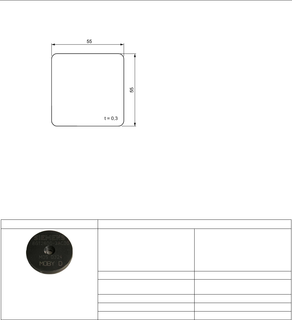
Figure 8-24 Dimension drawing of MDS D261
8.12
MDS D324
8.12.1
Characteristics
MDS D324
Characteristics
Area of application Production and distribution logistics
and product identification
Can also be used in harsh environ-
ments under extreme environmental
conditions (e.g. with higher temperature
load).
Memory size
992 bytes of EEPROM user memory
Write/read range See section "Field data of ISO tran-
sponders (MDS D) (Page 56)."
Mounting on metal
Yes, with spacer
ISO standard
ISO 15693
Degree of protection
IP67; IPx9K
ISO transponder
8.12 MDS D324
SIMATIC RF300
322 System Manual, 07/2017, C79000-G8976-C345-07
8.12.2
Ordering data
Table 8- 28 Ordering data MDS D324
Article number
MDS D324
6GT2600-3AC00
Table 8- 29 Ordering data MDS D324 accessories
Article number
Spacer
6GT2690-0AK00
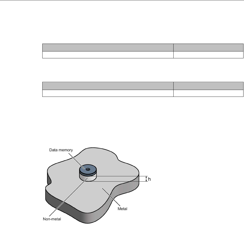
8.12.3
Mounting on metal
Mounting on metal
h
≥ 15 mm
Figure 8-25 Mounting the MDS D124/D324/D424/D524/E624 and RF320T on metal with spacer

ISO transponder
8.12 MDS D324
SIMATIC RF300
System Manual, 07/2017, C79000-G8976-C345-07 323
Flush-mounting
h
≥ 15 mm
a
≥ 25 mm
Figure 8-26 Flush-mounting of the MDS D124/D324/D424/D524/E624 and RF320T in metal with
spacer
Note
Going below the distances
If the distances (a and h) are not observed, a reduction of the field data results. It is possible
to mount the MDS with metal screws (M3 counters
unk head screws). This has no tangible
impact on the range.
8.12.4
Technical specifications
Table 8- 30 Technical specifications of MDS D324
6GT2600-3AC00
Product type designation
SIMATIC MDS D324
Memory
Memory configuration
• UID • 8 bytes
• User memory • 992 bytes EEPROM
• OTP memory • 16 bytes (EEPROM)
Read cycles (at < 40 ℃)
> 10
14
Write cycles (at < 40 ℃)
> 10
6
Data retention time (at < 40 ℃)
> 10 years

ISO transponder
8.12 MDS D324
SIMATIC RF300
324 System Manual, 07/2017, C79000-G8976-C345-07
6GT2600-3AC00
Write/read distance (Sg) Dependent on the reader used, see section "Field
data of ISO transponders (MDS D) (Page 56)"
MTBF (Mean Time Between Failures)
228 years
Mechanical specifications
Housing
• Material • Epoxy resin
• Color • Black
Recommended distance to metal
≥ 15 mm
Power supply
Inductive, without battery
Permitted ambient conditions
Ambient temperature
• during write/read access • -25 to +125 ℃
• outside the read/write field • -40 to +140 ℃
• during storage • -40 to +140 ℃
Degree of protection to EN 60529 • IP67
• IPx9K
Shock according to EN 60721-3-7 Class 7M3
1)
1000 m/s
2
Vibration according to EN 60721-3-7 Class 7M3
1)
200 m/s
2
Torsion and bending load
Not permitted
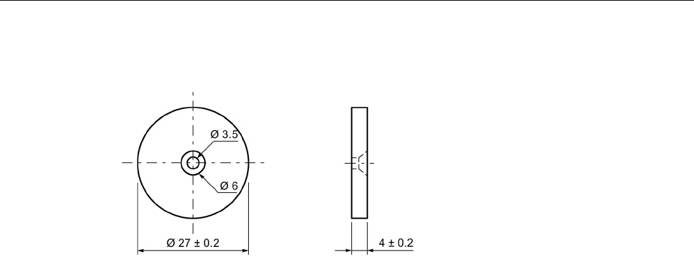
Design, dimensions and weight
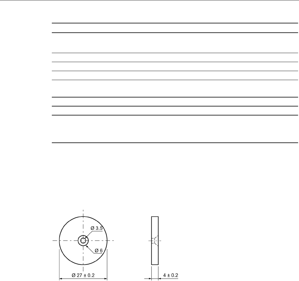
Dimensions (Ø x H)
27 x 4 mm
Weight
5 g
Type of mounting • 1 x M3 screw 2)
≤ 1 Nm
• Glued 3)
1)
The values for shock and vibration are maximum values and must not be applied continuously.
2
) To prevent it loosening during operation, secure the screw with screw locking varnish.
3) The processing instructions of the adhesive manufacturer must be observed.
ISO transponder
8.12 MDS D324
SIMATIC RF300
System Manual, 07/2017, C79000-G8976-C345-07 325
8.12.5
Dimension drawing
Figure 8-27 Dimension drawing of MDS D324
All dimensions in mm
ISO transponder
8.13 MDS D339
SIMATIC RF300
326 System Manual, 07/2017, C79000-G8976-C345-07
8.13
MDS D339
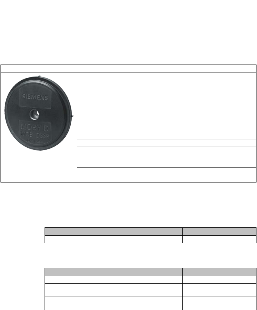
8.13.1
Characteristics
MDS D339
Characteristics
Area of application Applications in production automation with high
temperature demands (up to +220 °C)
Typical application areas:
• Paintshops and their preparatory treatments
• Primer coat, electrolytic dip area, cataphoresis
with the associated drying furnaces
• Top coat area with drying furnaces
• Washing areas at temperatures > 85 °C
• Other applications with higher temperatures
Memory size 992 bytes of EEPROM user memory
Write/read range See section Field data of ISO transponders (MDS D)
(Page 56).
Mounting on metal
Yes, with spacer
ISO standard
ISO 15693
Degree of protection
IP68/IPx9K
8.13.2
Ordering data
Table 8- 31 Ordering data for MDS D339
Article number
MDS D339
6GT2600-3AA10
Table 8- 32 Ordering data for MDS D339 accessories
Article number
Spacer
6GT2690-0AA00
Quick change holder
(Ø x H): 22 x 60 mm
6GT2690-0AH00
Quick change holder
(Ø x H): 22 x 47 mm
6GT2690-0AH10
ISO transponder
8.13 MDS D339
SIMATIC RF300
System Manual, 07/2017, C79000-G8976-C345-07 327
8.13.3
Mounting on metal
Direct mounting of the MDS D139/D339 on metal is not allowed. A distance of ≥ 30 mm is
recommended. This can be achieved using spacers (see "Ordering data (Page 326)").
Mounting on metal
h
≥ 30 mm
Figure 8-28 Mounting the MDS D139/D339 on metal with spacer
Flush-mounting
It is possible to mount the MDS D139/D339 in metal. With large antennas, for example ANT
D5, this leads to a reduction of ranges.
h
≥ 30 mm
a
≥ 100 mm
Figure 8-29 Flush-mounting of the MDS D139/D339 in metal with spacer

ISO transponder
8.13 MDS D339
SIMATIC RF300
328 System Manual, 07/2017, C79000-G8976-C345-07
Note
Going below the distances
If the distances (a and h) are not observed, a reduction of the field data results. It is possible
to mount the MDS with
metal screws (M5). This has no tangible impact on the range. It is
recommended that a test is performed in critical applications.
8.13.4
Cleaning the mobile data memory
Note
Do not clean the transponder with mechanical tools, sand
-blasting or pressure hose. These
cleaning methods result in damage to the transponder.
Clean the transponder only with the cleaning agents listed in the section "Chemical
resistance of the MDS".
8.13.5
Technical specifications
Table 8- 33 Technical specifications of MDS D339
6GT2600-3AA10
Product type designation
SIMATIC MDS D339
Memory
Memory configuration
• UID • 8 bytes
• User memory • 992 bytes EEPROM
• OTP memory • 16 bytes (EEPROM)
Read cycles (at < 40 ℃) > 1014
Write cycles (at < 40 ℃) > 106
Data retention time (at < 40 ℃)
> 10 years
Write/read distance (Sg) Dependent on the reader used, see section "Field
data of ISO transponders (MDS D) (Page 56)"
MTBF (Mean Time Between Failures)
228 years
Mechanical specifications
Housing
• Material • PPS

ISO transponder
8.13 MDS D339
SIMATIC RF300
System Manual, 07/2017, C79000-G8976-C345-07 329
6GT2600-3AA10
• Color • Black
Recommended distance to metal
≥ 30 mm
Power supply
Inductive, without battery
Permitted ambient conditions
Ambient temperature
• during write/read access • -25 to +100 ℃
• outside the read/write field • -40 to +220 ℃
• from +125 ℃: 20% reduction in the limit dis-
tance
• at +200 ℃: Tested up to 5000 hours or
6000 cycles
• at +220 ℃: Tested up to 2000 hours or
2000 cycles
• during storage • -40 to +100 ℃
Degree of protection to EN 60529 • IP68
2 hours, 2 bar, +20 °C
• IPx9K
steam jet: 150 mm; 10 to 15 l/min; 100 bar; 75
°C
Shock according to EN 60721-3-7 Class 7M3
1)
500 m/s
2
Vibration according to EN 60721-3-7 Class 7M3
1)
200 m/s
2
Torsion and bending load
Not permitted
Design, dimensions and weight
Dimensions (Ø x H)
85 x 15 mm
Weight
50 g
Type of mounting 1 x M5 screw 2)
1.5 Nm
1
The values for shock and vibration are maximum values and must not be applied continuously.
2)
For mounting with the spacer (6GT2690-0AA00), use a stainless steel M5 screw to avoid damag-
ing the MDS in high temperatures (expansion coefficient).
ISO transponder
8.13 MDS D339
SIMATIC RF300
330 System Manual, 07/2017, C79000-G8976-C345-07
8.13.6
Use of the MDS D339 in hazardous areas
The MDS D339 mobile data memory is classed as a piece of simple, electrical equipment
and can be operated in Protection Zone 2, Device Group II, Category 3G.
The following requirements of the 94/9/EC directive are met:
● EN 60079-0:2006
● EN 60079-15:2005
● EN 61241-0:2006
● EN 61241-1:2004
Identification
II 3 G Ex nA II T6
Ii 3 D Ex tD A22 IP68 T 210°C
KEMA 09 ATEX 0133 X
WARNING
Gefahr durch elektrostatische Entladungen
Potential electrostatic charging hazard
Danger potentiel de charges électrostatiques

ISO transponder
8.13 MDS D339
SIMATIC RF300
System Manual, 07/2017, C79000-G8976-C345-07 331
Note
Installations- und Betriebsbedingungen für den Ex-Schutzbereich:
a) Der Einsatz des Gerätes in der Nähe von stark ladungserzeugenden Prozessen ist
untersagt.
b) Das Gerät ist mechanisch geschützt zu montieren.
c) Die Montage muss auf eine
m geerdeten, leitenden Untergrund erfolgen.
d) Die Reinigung darf nur mit feuchtem Tuch erfolgen.
Installation and operating conditions for hazardous areas:
a) Use of the equipment in the vicinity of processes generating high charges is not allowed.
b) Th
e equipment must be mechanically protected when installed.
c) Installation must be performed on a grounded and conductive mounting surface.
d) Cleaning only with a wet cloth
Conditions d'installation et de mise en oeuvre pour la zone de protection Ex :
a)
L'utilisation de l'appareil près de processus générant de fortes charges est interdite.
b) L'appareil doit être monté de manière à être protégé mécaniquement.
c) Le montage doit être effectué sur un socle conducteur mis à la terre.
d) Nettoyage uniquement
avec un chiffon humide
ISO transponder
8.13 MDS D339
SIMATIC RF300
332 System Manual, 07/2017, C79000-G8976-C345-07
8.13.7
Dimensional drawing
MDS D339
Figure 8-30 Dimension drawing of the MDS D339
Dimensions in mm
ISO transponder
8.14 MDS D400
SIMATIC RF300
System Manual, 07/2017, C79000-G8976-C345-07 333
8.14
MDS D400
8.14.1
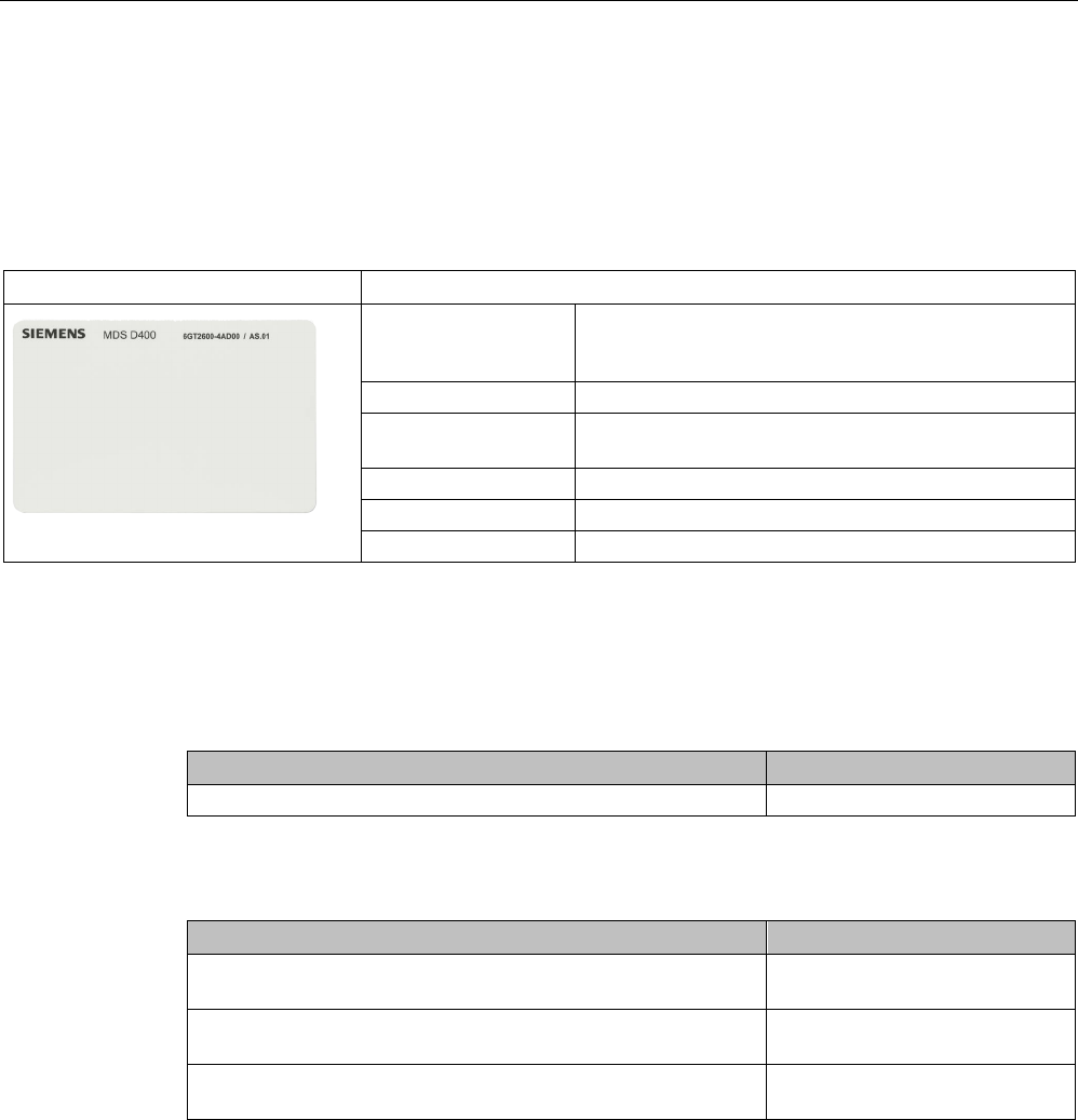
Features
MDS D400
Characteristics
Area of application Simple identification such as electronic barcode re-
placement/supplements, from warehouse and distribu-
tion logistics right through to product identification.
Memory size 2000 bytes of FRAM user memory
Write/read range See section "Field data of ISO transponders (MDS D)
(Page 56)"
Mounting on metal
Yes, with spacer
ISO standard
ISO 15693
Degree of protection
IP67
8.14.2
Ordering data
Table 8- 34 Ordering data of MDS D400
Article number
MDS D400
6GT2600-4AD00
Table 8- 35 Ordering data of MDS D400 accessories
Article number
Spacer
(in conjunction with fixing pocket 6GT2190-0AB00)
6GT2190-0AA00
Fixing pocket
(in conjunction with spacer 6GT2190-0AA00)
6GT2190-0AB00
Fixing pocket
(not suitable for fixing directly onto metal)
6GT2390-0AA00
ISO transponder
8.14 MDS D400
SIMATIC RF300
334 System Manual, 07/2017, C79000-G8976-C345-07
8.14.3
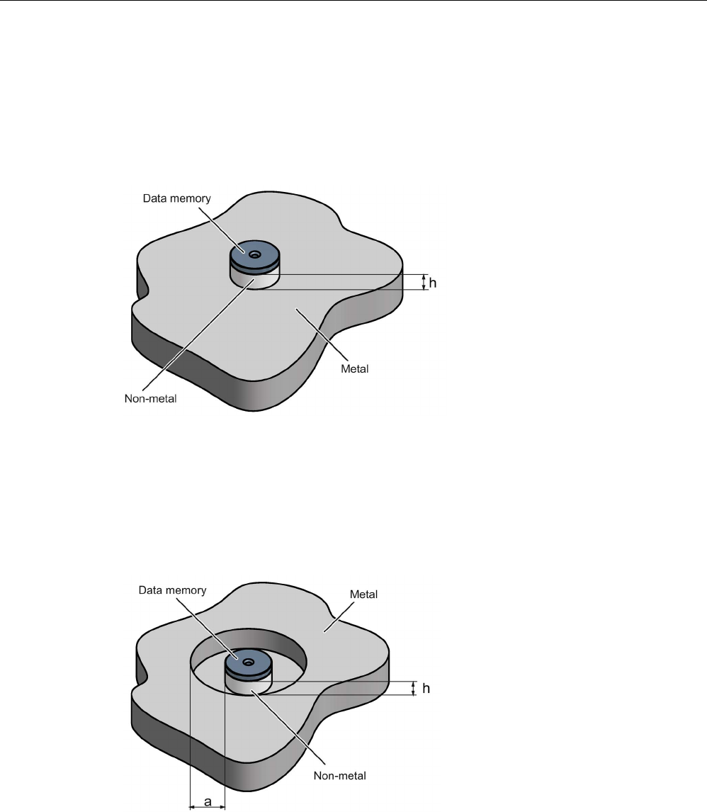
Mounting on metal
Mounting on metal
It is possible to mount the MDS D400 on metal.
h
≥ 20 mm
①
Transponder
②
Metal
③
Non-metal
Figure 8-31 Mounting of the MDS D400 on metal with spacer
ISO transponder
8.14 MDS D400
SIMATIC RF300
System Manual, 07/2017, C79000-G8976-C345-07 335
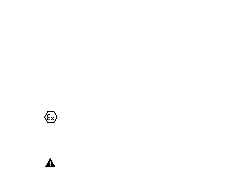
Flush-mounted in metal
a
≥ 20 mm
h
≥ 20 mm
①
Transponder
②
Metal
③
Non-metal
Figure 8-32 Flush-mounting of MDS D400 in metal with spacer
Note
If the minimum guide values (h) are not observed, th
is will result in a reduction of the field
data.
8.14.4
Technical specifications
Table 8- 36 Technical specifications for MDS D400
6GT2600-4AD00
Product type designation
SIMATIC MDS D400
Memory
Memory configuration
• UID • 8 bytes
• User memory • 2000 bytes FRAM

ISO transponder
8.14 MDS D400
SIMATIC RF300
336 System Manual, 07/2017, C79000-G8976-C345-07
6GT2600-4AD00
• OTP memory • 16 bytes FRAM
Read cycles (at < 25 ℃)
> 10
12
Write cycles (at < 25 ℃)
> 10
12
Data retention time (at < 25 ℃)
> 10 years
Write/read distance (Sg) Dependent on the reader used, see section "Field
data of ISO transponders (MDS D) (Page 56)"
MTBF (Mean Time Between Failures)
228 years
Mechanical specifications
Housing
• Material • PVC
• Color • White
Recommended distance to metal
≥ 20 mm
Power supply
Inductive, without battery
Permitted ambient conditions
Ambient temperature
• during write/read access • -20 to +60 ℃
• outside the read/write field • -20 to +60 ℃
• during storage • -20 to +60 ℃
Degree of protection to EN 60529
IP67
Vibration-resistant to EN 60721-3-7, class 7M3
ISO 10373 / ISO 7810
1)
Torsion and bending load
ISO 10373/ISO 7816-1
Design, dimensions and weight
Dimensions (L x W x H)
85 x 54 x 0.8 mm
Weight
5 g
Type of mounting • Fixing lug
• Glued 2)
1)
The values for vibration are maximum values and must not be applied continuously.
2) The processing instructions of the adhesive manufacturer must be observed.
ISO transponder
8.14 MDS D400
SIMATIC RF300
System Manual, 07/2017, C79000-G8976-C345-07 337
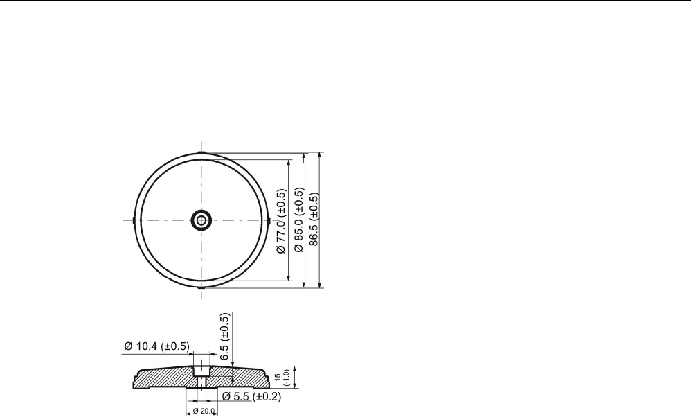
8.14.5
Dimension drawing
Figure 8-33 Dimensional drawing MDS D400 (dimensions in mm)
ISO transponder
8.15 MDS D421
SIMATIC RF300
338 System Manual, 07/2017, C79000-G8976-C345-07
8.15
MDS D421
8.15.1
Characteristics
MDS D421
Characteristics
Area of application The MDS D421 is designed for tool coding in accordance
with DIN 69873.
It can be used wherever small data carriers and exact posi-
tioning are required, e.g. tool identification, workpiece hold-
ers.
The rugged housing of the MDS D421 means that it can
also be used in a harsh industrial environment without prob-
lems.
Memory size
2000 bytes of FRAM user memory
Write/read range See section "Field data of ISO transponders (MDS D)
(Page 56)"
Mounting on metal
Yes, flush-mounted in metal
ISO standard
ISO 15693
Degree of protection
IP67/IPx9K
8.15.2
Ordering data
Table 8- 37 Ordering data of MDS D421
Article number
MDS D421
6GT2600-4AE00
ISO transponder
8.15 MDS D421
SIMATIC RF300
System Manual, 07/2017, C79000-G8976-C345-07 339
8.15.3
Mounting on metal
Mounting on metal
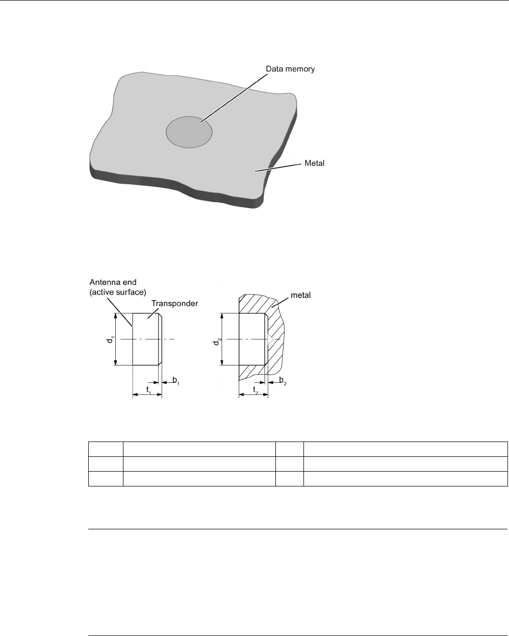
Figure 8-34 Mounting of MDS D421/D521/E623 on metal
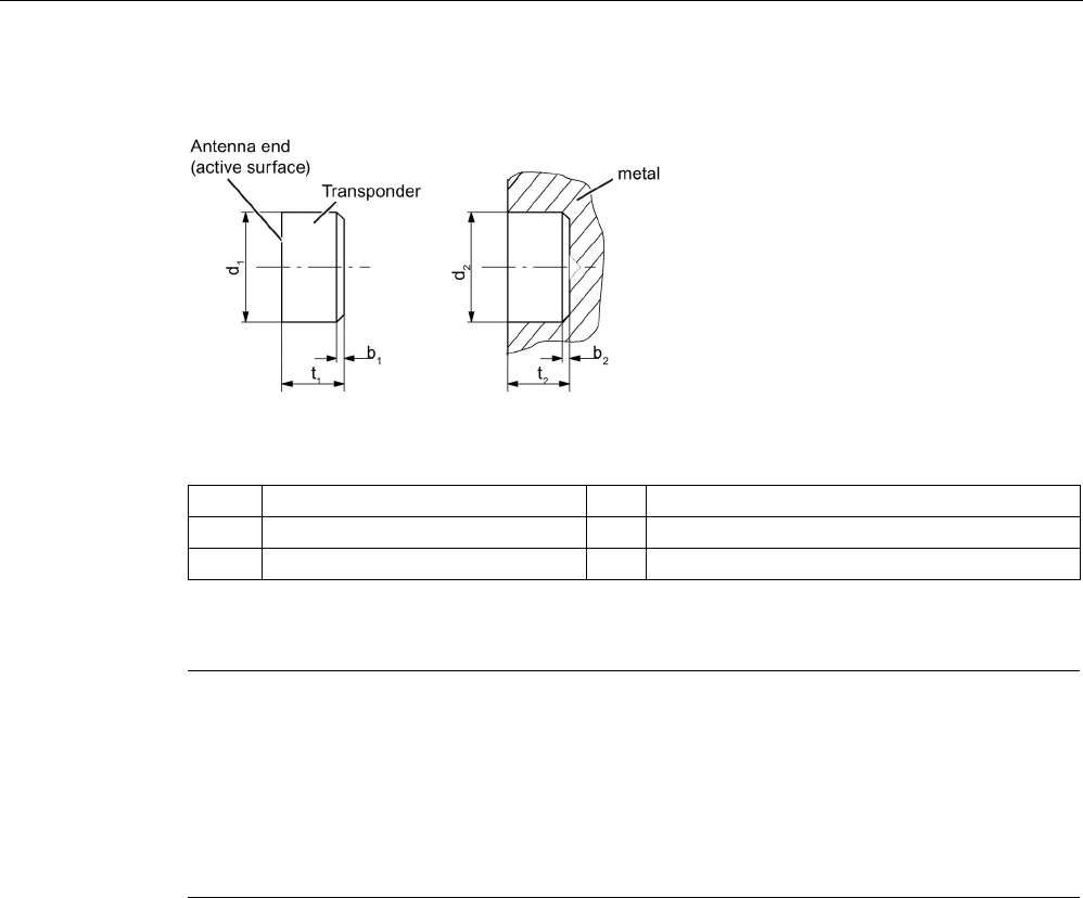
Flush-mounting
Figure 8-35 Mounting of MDS D421/D521/E623 in metal
ISO transponder
8.15 MDS D421
SIMATIC RF300
340 System Manual, 07/2017, C79000-G8976-C345-07
Flush-mounting of the MDS in metal with tools
Figure 8-36 Flush-mounting of MDS D421/D521/E623 in metal with tools
b1
0.5 x 45°
b2
0.3 x 45° or R0.3
d
1
10 (-0.04... -0.13)
d
2
10 (+0.09... 0)
t1
4.5 (-0 ... -0.1)
t2
4.6 (+0.2 ... 0)
All dimensions in mm
Note
Installation instruction
The MDS s
hould not protrude out of the locating hole; it must be flush with the outside
contour.
The mounting instructions of the MDS and the conditions associated with the application
(e.g. peripheral speed, temperature, and use of coolant) must be observed during
the
installation.
Mounting information for adhesion
● Drill installation hole
● The adhesive surfaces must be dry, free from dust, oil, stripping agents and other
impurities
● Apply adhesive according to the manufacturer's processing instructions
● Press in transponder using your fingers; with antenna side to the outside (see figure
above)
● Remove residues of adhesive
● Allow to cure according to the manufacturer's instructions
● Flush-mounting of the transponder in metal with tools
ISO transponder
8.15 MDS D421
SIMATIC RF300
System Manual, 07/2017, C79000-G8976-C345-07 341
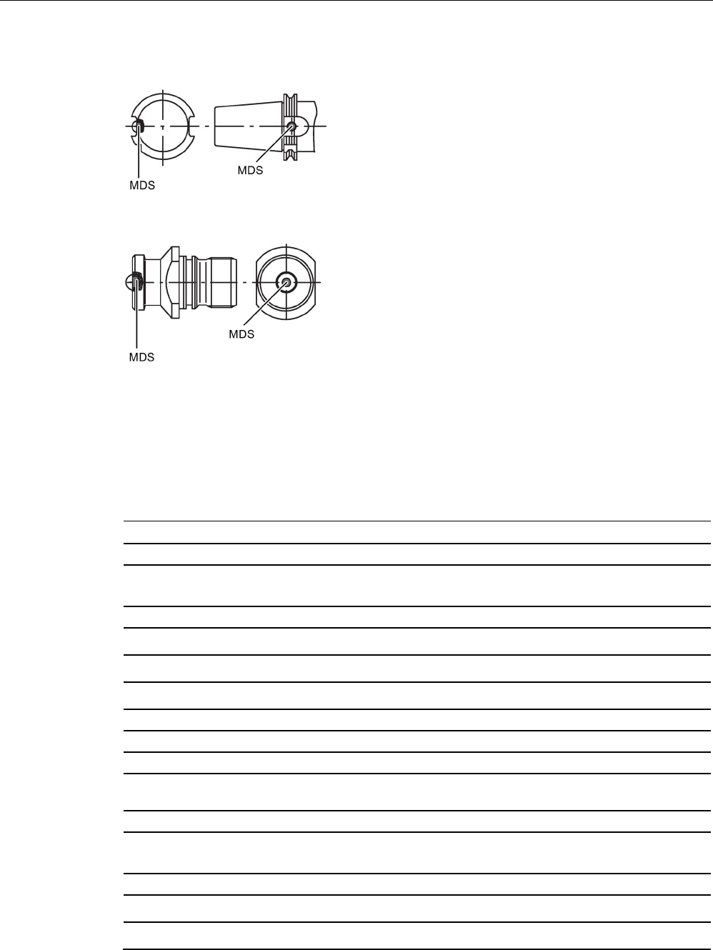
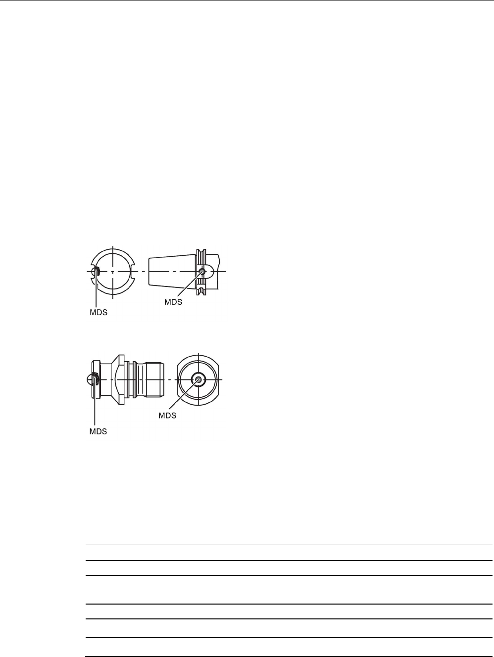
Installation examples
Figure 8-37 Installation example of MDS D421/D521/E623 in a steep cone
Figure 8-38 Installation example of MDS D421/D521/E623 in a stud bolt
8.15.4
Technical specifications
Table 8- 38 Technical specifications for the MDS D421
6GT2600-4AE00
Product type designation
SIMATIC MDS D421
Memory
Memory configuration
• UID • 8 bytes
• User memory • 2000 bytes FRAM
• OTP memory • 16 bytes FRAM
Read cycles (at < 40 ℃)
> 10
12
Write cycles (at < 40 ℃)
> 10
12
Data retention time (at < 40 ℃)
> 10 years
Write/read distance (Sg) Dependent on the reader used, see section "Field
data of ISO transponders (MDS D) (Page 56)"
MTBF (Mean Time Between Failures)
228 years
Mechanical specifications
Housing
• Material • Epoxy resin
• Color • Black
ISO transponder
8.15 MDS D421
SIMATIC RF300
342 System Manual, 07/2017, C79000-G8976-C345-07
6GT2600-4AE00
Recommended distance to metal
≥ 0 mm
Power supply
Inductive, without battery
Permitted ambient conditions
Ambient temperature
• during write/read access • -25 to +85 ℃
• outside the read/write field • -40 to +100 ℃
• during storage • -40 to +100 ℃
Degree of protection to EN 60529 • IP67
• IPx9K
steam jet: 150 mm; 10 to 15 l/min; 100 bar; 75
°C
Shock according to EN 60721-3-7 Class 7M3
1)
1000 m/s
2
Vibration according to EN 60721-3-7 Class 7M3
1)
200 m/s
2
Torsion and bending load
Not permitted
Design, dimensions and weight
Dimensions (Ø x H)
10 x 4.5 mm
Weight
Approx. 1 g
Type of mounting
Glued
2)
1)
The values for shock and vibration are maximum values and must not be applied continuously.
2) The processing instructions of the adhesive manufacturer must be observed.
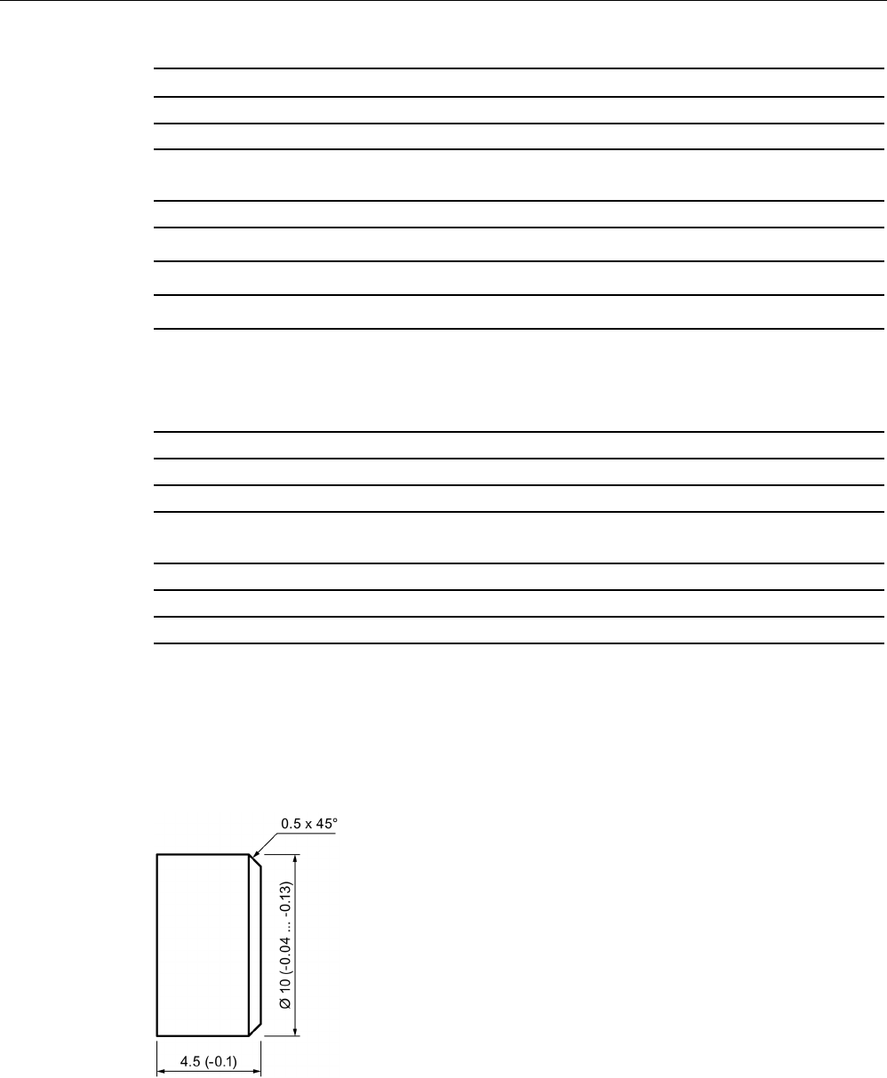
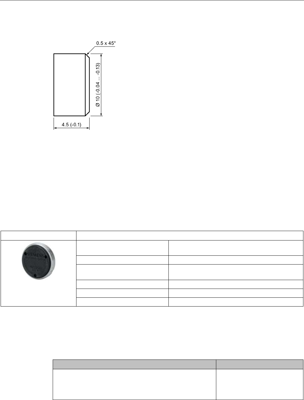
8.15.5
Dimension drawing
Figure 8-39 Dimension drawing of MDS D421
All dimensions in mm

ISO transponder
8.16 MDS D422
SIMATIC RF300
System Manual, 07/2017, C79000-G8976-C345-07 343
8.16
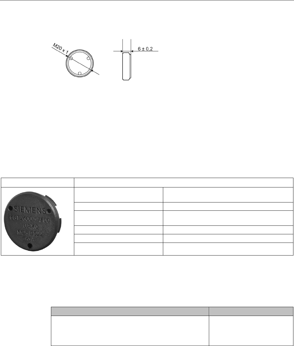
MDS D422
8.16.1
Characteristics
MDS D422
Characteristics
Area of application Identification of metallic workpiece holders, workpieces or
containers
Memory size
2000 bytes of FRAM user memory
Write/read range See section "Field data of ISO transponders (MDS D)
(Page 56).
Mounting on metal
Yes
ISO standard
ISO 15693
Degree of protection
IP68
8.16.2
Ordering data
Table 8- 39 Ordering data of MDS D422
Article number
MDS D422
A screw-in aid is included in the scope of supply per packaging
unit
6GT2600-4AF00

ISO transponder
8.16 MDS D422
SIMATIC RF300
344 System Manual, 07/2017, C79000-G8976-C345-07
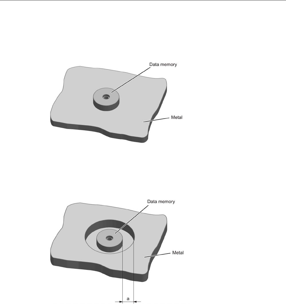
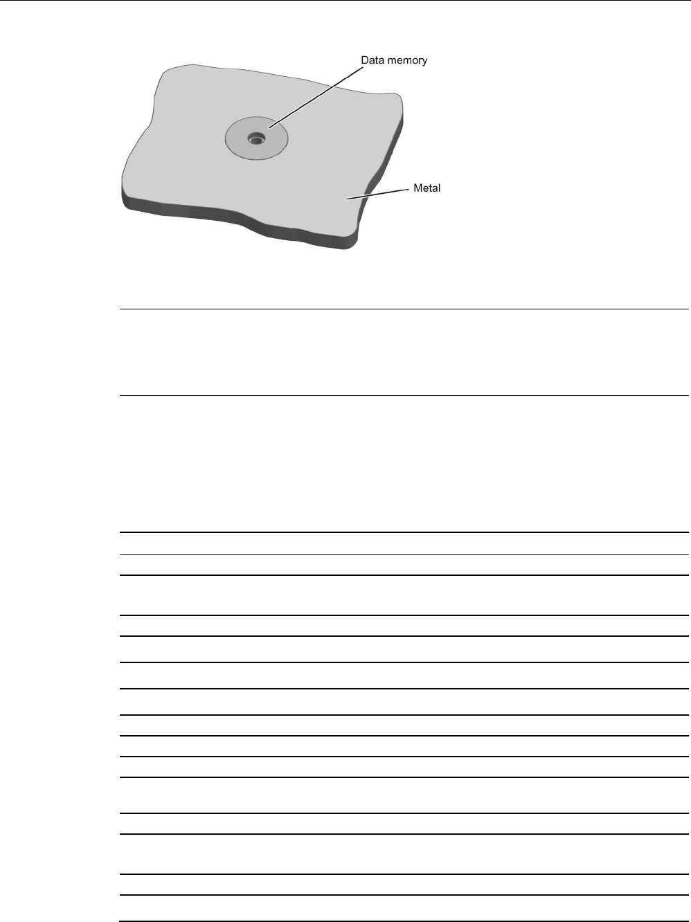
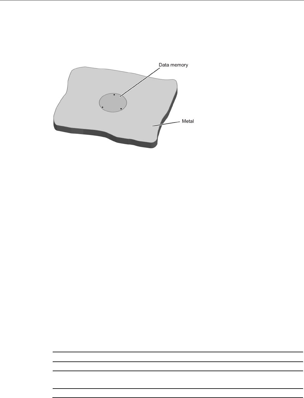
8.16.3
Mounting in metal
Flush-mounting
Figure 8-40 Mounting of MDS D422 in metal
Mounting information for screws
You can screw the transponder into a pre-drilled threaded hole using the screw-in aid.
Mounting information for adhesion
● Drill installation hole
● The adhesive surfaces must be dry, free from dust, oil, stripping agents and other
impurities
● Apply adhesive according to the manufacturer's processing instructions
● Press in MDS D422 using your fingers; with antenna to the outside
● Remove residues of adhesive
● Allow to cure according to the manufacturer's instructions
● Flush-mounting of MDS D422 in metal with tools
8.16.4
Technical specifications
Table 8- 40 Technical specifications for the MDS D422
6GT2600-4AF00
Product type designation
SIMATIC MDS D422
Memory
Memory configuration

ISO transponder
8.16 MDS D422
SIMATIC RF300
System Manual, 07/2017, C79000-G8976-C345-07 345
6GT2600-4AF00
• UID • 8 bytes
• User memory • 2000 bytes FRAM
• OTP memory • 16 bytes FRAM
Read cycles (at < 40 ℃)
> 10
12
Write cycles (at < 40 ℃)
> 10
12
Data retention time (at < 40 ℃)
> 10 years
Write/read distance (Sg) Dependent on the reader used, see section "Field
data of ISO transponders (MDS D) (Page 56)"
MTBF (Mean Time Between Failures)
285 years
Mechanical specifications
Housing
• Material • Plastic PA 6.6 GF; brass nickel plated
• Color • Black/silver
Recommended distance to metal
≥ 0 mm
Power supply
Inductive, without battery
Permitted ambient conditions
Ambient temperature
• during write/read access • -25 to +85 ℃
• outside the read/write field • -40 to +100 ℃
• during storage • -40 to +100 ℃
Degree of protection to EN 60529 IP68
2 hours, 2 bar, +20 °C
Shock according to EN 60721-3-7 Class 7M3
1)
500 m/s
2
Vibration according to EN 60721-3-7 Class 7M3
1)
200 m/s
2
Torsion and bending load
Not permitted
Design, dimensions and weight
Dimensions (Ø x H)
20 x 6 mm
Weight
13 g
Type of mounting • Glued 2)
• 1 x transponder thread M20
≤ 1 Nm
1)
The values for shock and vibration are maximum values and must not be applied continuously.
2) The processing instructions of the adhesive manufacturer must be observed.
ISO transponder
8.17 MDS D423
SIMATIC RF300
346 System Manual, 07/2017, C79000-G8976-C345-07
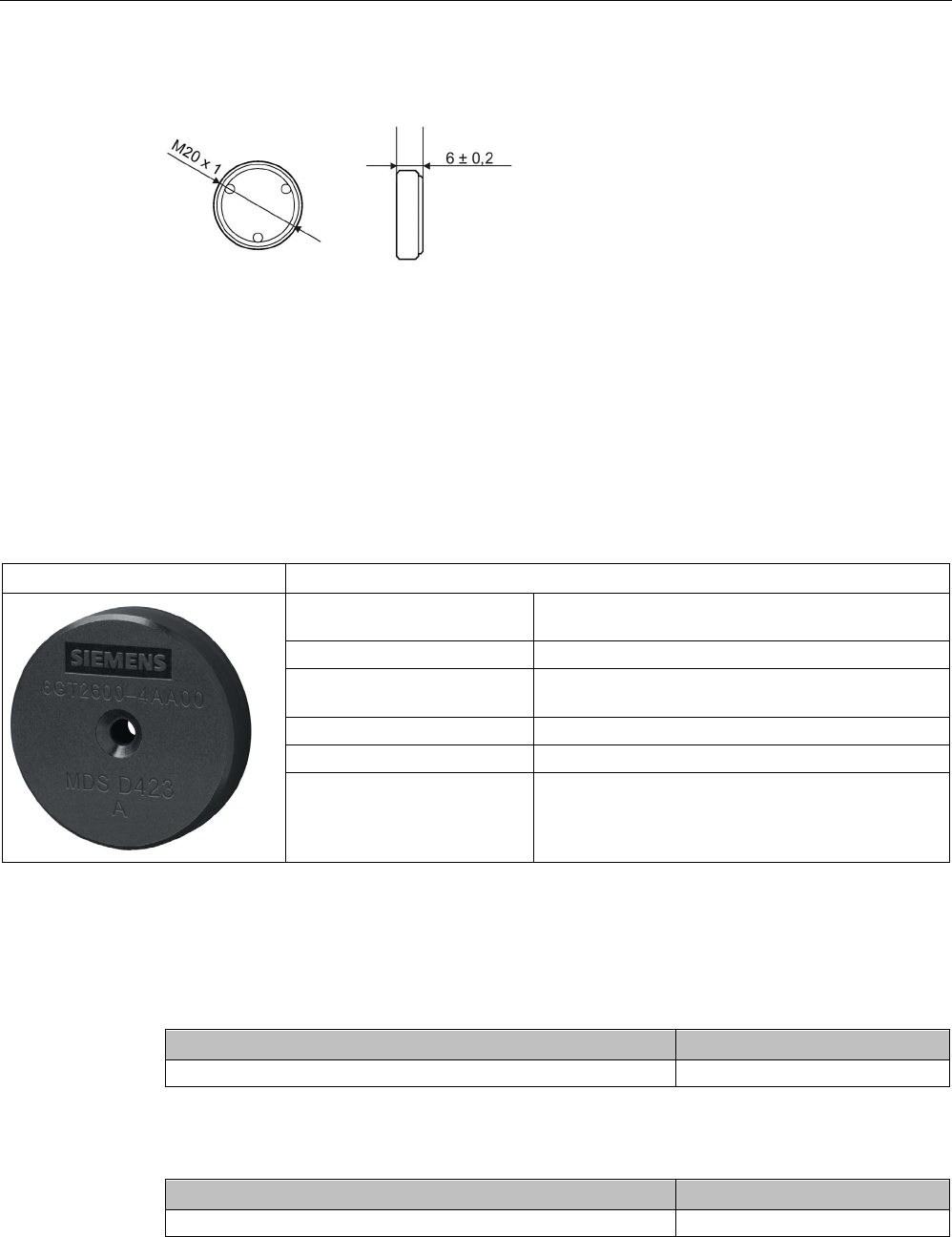
8.16.5
Dimension drawing
Dimensions in mm
Figure 8-41 Dimensional drawing of MDS D422
8.17
MDS D423
8.17.1
Characteristics
MDS D423
Characteristics
Area of application Identification of metallic workpiece holders, work-
pieces or containers, production automation
Memory size 2000 bytes of FRAM user memory
Write/read range See section "Field data of ISO transponders (MDS
D) (Page 56)"
Mounting on metal Yes, flush-mounted in metal
ISO standard
ISO 15693
Degree of protection IP68/IPx9K
8.17.2
Ordering data
Table 8- 41 Ordering data of MDS D423
Article number
MDS D423
6GT2600-4AA00
Table 8- 42 Ordering data of MDS D423 accessories
Article number
Fixing hood RF330T / MDS D423
6GT2690-0AE00
ISO transponder
8.17 MDS D423
SIMATIC RF300
System Manual, 07/2017, C79000-G8976-C345-07 347
8.17.3
Mounting on metal
Mounting on metal
Direct mounting of the MDS D423 on metal is possible.
Figure 8-42 Mounting the MDS D423 on metal
Flush-mounted in metal
It is possible to mount the MDS D423 in metal.
a
≥ 10 mm
Figure 8-43 Flush-mounting of the MDS D423 in metal with 10 mm clearance
ISO transponder
8.17 MDS D423
SIMATIC RF300
348 System Manual, 07/2017, C79000-G8976-C345-07
Figure 8-44 Flush-mounting of the MDS D423 in metal without clearance
Note
Reduction of the write/read range
Note that when the device is flush
-mounted in metal without a surrounding clearance ≥ 10
mm, the write/read range is significantly reduced.
8.17.4
Technical specifications
Table 8- 43 Technical specifications of MDS D423
6GT2600-4AA00
Product type designation
SIMATIC MDS D423
Memory
Memory configuration
• UID • 8 bytes
• User memory • 2000 bytes FRAM
• OTP memory • 16 bytes FRAM
Read cycles (at < 40 ℃)
> 10
12
Write cycles (at < 40 ℃)
> 10
12
Data retention time (at < 40 ℃)
> 10 years
Write/read distance (Sg) Dependent on the reader used, see section "Field
data of ISO transponders (MDS D) (Page 56)"
MTBF (Mean Time Between Failures)
228 years
Mechanical specifications
Housing
• Material • Plastic PPS

ISO transponder
8.17 MDS D423
SIMATIC RF300
System Manual, 07/2017, C79000-G8976-C345-07 349
6GT2600-4AA00
• Color • Black
Recommended distance to metal
≥ 0 mm
Power supply
Inductive, without battery
Permitted ambient conditions
Ambient temperature
• during write/read access • -25 to +85 ℃
• outside the read/write field • -40 to +100 ℃
• during storage • -40 to +100 ℃
Degree of protection to EN 60529 • IP68
2 hours, 2 bar, +20 °C
• IPx9K
steam jet: 150 mm; 10 to 15 l/min; 100 bar; 75
°C
Shock according to EN 60721-3-7 Class 7M3
1)
500 m/s
2
Vibration according to EN 60721-3-7 Class 7M3
1)
200 m/s
2
Pressure resistance • Low pressure resistant
vacuum dryer: up to 20 mbar
• High pressure resistant
(see degree of protection IPx9K)
Torsion and bending load
Not permitted
Design, dimensions and weight
Dimensions (Ø x H)
30 x 8 mm
Weight
15 g
Type of mounting 1 x M4 screw 2)
≤ 1 Nm
1)
The values for shock and vibration are maximum values and must not be applied continuously.
2 ) To prevent it loosening during operation, secure the screw with screw locking varnish.
ISO transponder
8.18 MDS D424
SIMATIC RF300
350 System Manual, 07/2017, C79000-G8976-C345-07
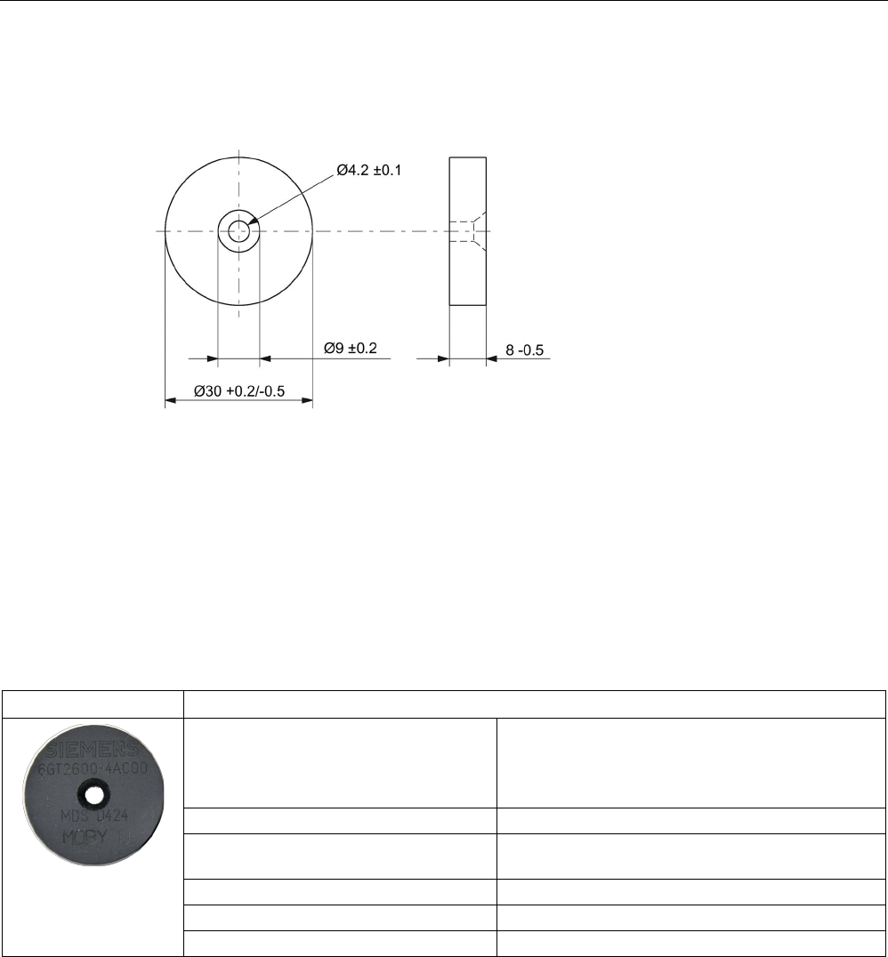
8.17.5
Dimensional drawing
Dimensions in mm
Figure 8-45 Dimension drawing for MDS D423
8.18
MDS D424
8.18.1
Characteristics
MDS D424
Characteristics
Area of application Production and distribution logistics as well as in
assembly and production lines,
can also be used in a harsh industrial environment
without problem
Memory size
2000 bytes of FRAM user memory
Write/read range See section "Field data of ISO transponders (MDS
D) (Page 56)."
Mounting on metal
Yes, with spacer
ISO standard
ISO 15693
Degree of protection
IP67; IPx9K

ISO transponder
8.18 MDS D424
SIMATIC RF300
System Manual, 07/2017, C79000-G8976-C345-07 351
8.18.2
Ordering data
Table 8- 44 Ordering data of MDS D424
Article number
MDS D424
6GT2600-4AC00
Table 8- 45 Ordering data of MDS D424 accessories
Article number
Spacer
6GT2690-0AK00
8.18.3
Mounting on metal
Mounting on metal
h
≥ 15 mm
Figure 8-46 Mounting the MDS D124/D324/D424/D524/E624 and RF320T on metal with spacer
ISO transponder
8.18 MDS D424
SIMATIC RF300
352 System Manual, 07/2017, C79000-G8976-C345-07
Flush-mounting
h
≥ 15 mm
a
≥ 25 mm
Figure 8-47 Flush-mounting of the MDS D124/D324/D424/D524/E624 and RF320T in metal with
spacer
Note
Going below the distances
If the distances (a and h) are not observed,
a reduction of the field data results. It is possible
to mount the MDS with metal screws (M3 countersunk head screws). This has no tangible
impact on the range.
8.18.4
Technical specifications
Table 8- 46 Technical specifications for the MDS D424
6GT2600-4AC00
Product type designation
SIMATIC MDS D424
Memory
Memory configuration
• UID • 8 bytes
• User memory • 2000 bytes FRAM
• OTP memory • 16 bytes FRAM
Read cycles (at < 40 ℃)
> 10
12
Write cycles (at < 40 ℃)
> 10
12
Data retention time (at < 40 ℃)
> 10 years

ISO transponder
8.18 MDS D424
SIMATIC RF300
System Manual, 07/2017, C79000-G8976-C345-07 353
6GT2600-4AC00
Write/read distance (Sg) Dependent on the reader used, see section "Field
data of ISO transponders (MDS D) (Page 56)"
MTBF (Mean Time Between Failures)
228 years
Mechanical specifications
Housing
• Material • Epoxy resin
• Color • Black
Recommended distance to metal
≥ 15 mm
Power supply
Inductive, without battery
Permitted ambient conditions
Ambient temperature
• during write/read access • -25 to +85 ℃
• outside the read/write field • -40 to +100 ℃
• during storage • -40 to +100 ℃
Degree of protection to EN 60529 • IP67
• IPx9K
Shock according to EN 60721-3-7 Class 7M3
1)
1000 m/s
2
Vibration according to EN 60721-3-7 Class 7M3
1)
200 m/s
2
Torsion and bending load
Not permitted
Design, dimensions and weight
Dimensions (Ø x H)
27 x 4 mm
Weight
5 g
Type of mounting • Glued 2)
• 1x screw M3 3)
≤ 1 Nm
1)
The values for shock and vibration are maximum values and must not be applied continuously.
2)
The processing instructions of the adhesive manufacturer must be observed.
3 ) To prevent it loosening during operation, secure the screw with screw-locking varnish.
ISO transponder
8.19 MDS D425
SIMATIC RF300
354 System Manual, 07/2017, C79000-G8976-C345-07
8.18.5
Dimension drawing
Figure 8-48 Dimension drawing of MDS D424
All dimensions in mm
8.19
MDS D425
8.19.1
Characteristics
MDS D425
Characteristics
Area of application Compact and rugged ISO transponder; suitable for screw
mounting
Use in assembly and production lines in the powertrain
sector; ideal for mounting on motors, gearboxes, and work-
piece holders
Rugged packaging of the MDS D425; can therefore also be
used under extreme environmental conditions without prob-
lem
Memory size
2000 bytes of FRAM user memory
Write/read range See section "Field data of ISO transponders (MDS D)
(Page 56)".
Mounting on metal
Yes
ISO standard ISO 15693
Degree of protection
IP68/IPx9K
ISO transponder
8.19 MDS D425
SIMATIC RF300
System Manual, 07/2017, C79000-G8976-C345-07 355
8.19.2
Ordering data
Table 8- 47 Ordering data of MDS D425
Article number
MDS D425
6GT2600-4AG00
8.19.3
Application example
Figure 8-49 Application example
8.19.4
Technical specifications
Table 8- 48 Technical specifications for the MDS D425
6GT2600-4AG00
Product type designation
SIMATIC MDS D425
Memory
Memory configuration
• UID • 8 bytes
• User memory • 2000 bytes FRAM
• OTP memory • 16 bytes FRAM

ISO transponder
8.19 MDS D425
SIMATIC RF300
356 System Manual, 07/2017, C79000-G8976-C345-07
6GT2600-4AG00
Read cycles (at < 40 ℃)
> 10
12
Write cycles (at < 40 ℃)
> 10
12
Data retention time (at < 40 ℃)
> 10 years
Write/read distance (Sg) Dependent on the reader used, see section "Field
data of ISO transponders (MDS D) (Page 56)"
MTBF (Mean Time Between Failures)
228 years
Mechanical specifications
Housing
• Material • Plastic PA 6.6 GF
• Color • Black
Recommended distance to metal
≥ 0 mm
Power supply
Inductive, without battery
Permitted ambient conditions
Ambient temperature
• during write/read access • -25 to +85 ℃
• outside the read/write field • -40 to +125 ℃
• during storage • -40 to +125 ℃
Degree of protection to EN 60529 • IP68
2 hours, 2 bar, +20 °C
• IPx9K
steam jet: 150 mm; 10 to 15 l/min; 100 bar; 75
°C
Shock according to IEC 68-2-27
1)
500 m/s
2
Vibration according to IEC 68-2-6
1)
200 m/s
2
Torsion and bending load
Not permitted
Design, dimensions and weight
Dimensions (Ø x H)
24 x 10 mm (without set screw)
Weight
35 g
Type of mounting 1x transponder set screw M6
SW 22; ≤ 6 Nm
1) The values for shock and vibration are maximum values and must not be applied continuously.
ISO transponder
8.20 MDS D426
SIMATIC RF300
System Manual, 07/2017, C79000-G8976-C345-07 357
8.19.5
Dimension drawing
Dimensions in mm
Figure 8-50 Dimension drawing of MDS D425
8.20
MDS D426
8.20.1
Characteristics
MDS D426
Characteristics
Area of application Compact and rugged ISO transponder; suitable for identification of
transport units in production-related logistics; can also be deployed in
harsh conditions
Memory size
2000 bytes of FRAM user memory
Write/read range
See section Field data of ISO transponders (MDS D) (Page 56)
Mounting on metal
Yes, with spacer
ISO standard
ISO 15693
Degree of protection
IP68
ISO transponder
8.20 MDS D426
SIMATIC RF300
358 System Manual, 07/2017, C79000-G8976-C345-07
8.20.2
Ordering data
Table 8- 49 Ordering data of MDS D426
Article number
MDS D426
6GT2600-4AH00
Table 8- 50 Ordering data of MDS D426 accessories
Article number
Spacer
6GT2690-0AL00
8.20.3
Mounting on metal
Mounting on metal
h
≥ 25 mm
Figure 8-51 Mounting the MDS D126 / D426 / D526 on metal with spacer
ISO transponder
8.20 MDS D426
SIMATIC RF300
System Manual, 07/2017, C79000-G8976-C345-07 359
Flush-mounted in metal
h
≥ 25 mm
a
≥ 50 mm
Figure 8-52 Flush installation of the MDS D126 / D426 / D526 in metal with spacer
8.20.4
Technical specifications
Table 8- 51 Technical specifications for the MDS D426
6GT2600-4AH00
Product type designation
SIMATIC MDS D426
Memory
Memory configuration
• UID • 8 bytes
• User memory • 2000 bytes FRAM
• OTP memory • 16 bytes FRAM
Read cycles (at < 40 ℃)
> 10
12
Write cycles (at < 40 ℃)
> 10
12
Data retention time (at < 40 ℃) > 10 years
Write/read distance (Sg) Dependent on the reader used, see section "Field
data of ISO transponders (MDS D) (Page 56)"
MTBF (Mean Time Between Failures) 228 years
Mechanical specifications
Housing
• Material • Plastic PA 6.6 GF
• Color • Black
Recommended distance to metal
≥ 25 mm
ISO transponder
8.20 MDS D426
SIMATIC RF300
360 System Manual, 07/2017, C79000-G8976-C345-07
6GT2600-4AH00
Power supply
Inductive, without battery
Permitted ambient conditions
Ambient temperature
• during write/read access • -25 to +85 ℃
• outside the read/write field • -40 to +100 ℃
• during storage • -40 to +100 ℃
Degree of protection to EN 60529 IP68
2 hours, 2 bar, +20 °C
Shock according to IEC 68-2-27
1)
50 m/s
2
Vibration according to IEC 68-2-6
1)
20 m/s
2
Torsion and bending load
Not permitted
Design, dimensions and weight
Dimensions (Ø x H)
50 x 3.6 mm
Weight
13 g
Type of mounting 1 x M4 screw 2)
≤ 1 Nm
1)
The values for shock and vibration are maximum values and must not be applied continuously.
2 ) To prevent it loosening during operation, secure the screw with screw locking varnish.
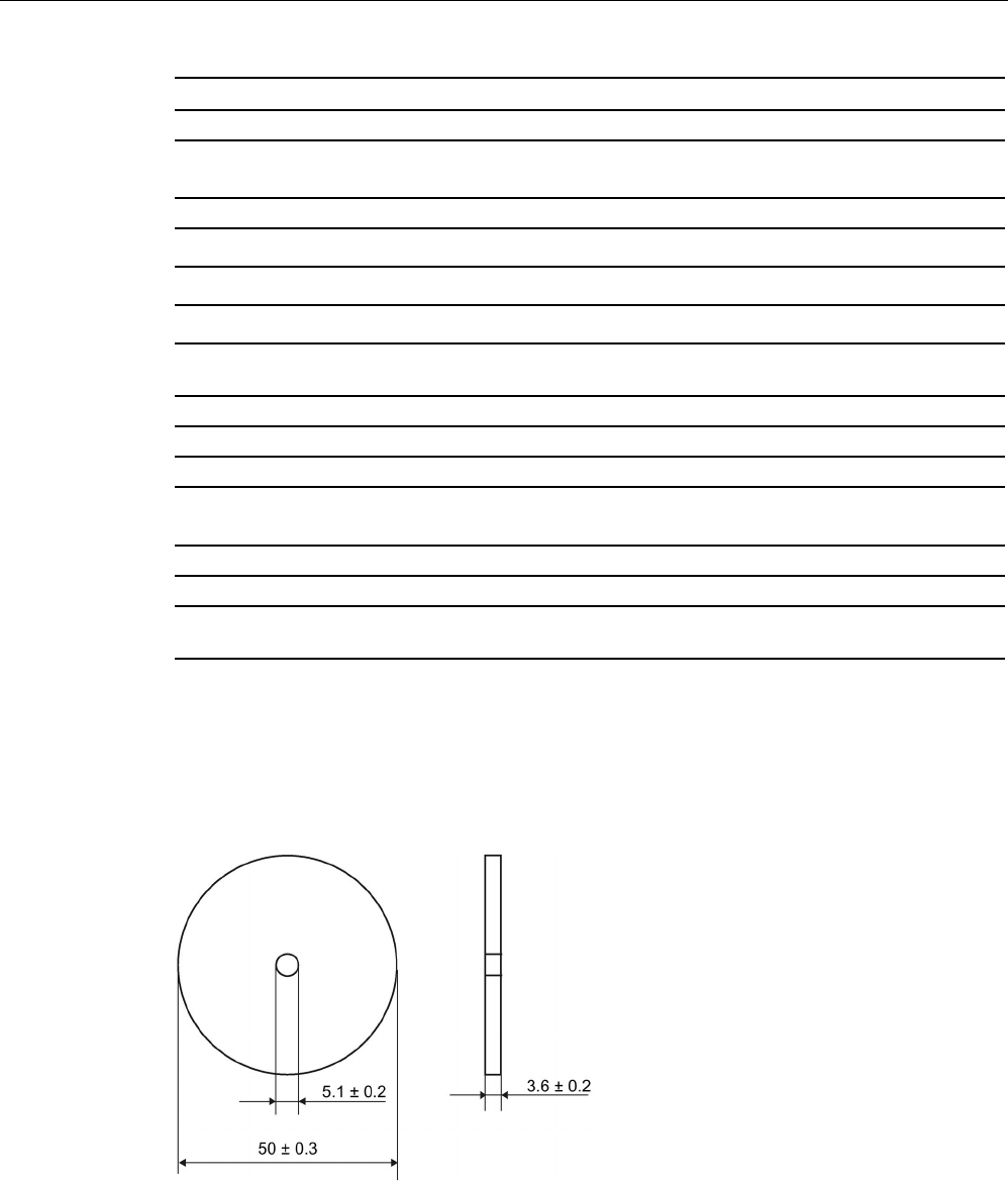
8.20.5
Dimension drawing
Dimensions in mm
Figure 8-53 Dimension drawing of MDS D426
ISO transponder
8.21 MDS D428
SIMATIC RF300
System Manual, 07/2017, C79000-G8976-C345-07 361
8.21
MDS D428
8.21.1
Characteristics
MDS D428
Characteristics
Area of application Compact and rugged ISO transponder; suitable for screw
mounting.
Use in assembly and production lines in the powertrain
sector.
The rugged housing of the MDS D428 means that it can
also be used in extreme environmental conditions without
problems.
Memory size
2000 bytes of FRAM user memory
Write/read range See section "Field data of ISO transponders (MDS D)
(Page 56)"
Mounting on metal
Yes
ISO standard
ISO 15693
Degree of protection
IP68/IPx9K
8.21.2
Ordering data
Table 8- 52 Ordering data of MDS D428
Article number
MDS D428
6GT2600-4AK00-0AX0

ISO transponder
8.21 MDS D428
SIMATIC RF300
362 System Manual, 07/2017, C79000-G8976-C345-07
8.21.3
Application example
Figure 8-54 Application example
8.21.4
Technical specifications
Table 8- 53 Technical specifications for the MDS D428
6GT2600-4AK00
Product type designation SIMATIC MDS D428
Memory
Memory configuration
• UID • 8 bytes
• User memory • 2000 bytes FRAM
• OTP memory • 16 bytes FRAM
Read cycles (at < 40 ℃) > 1012
Write cycles (at < 40 ℃)
> 10
12
Data retention time (at < 40 ℃)
> 10 years
Write/read distance (Sg) Dependent on the reader used, see section "Field
data of ISO transponders (MDS D) (Page 56)"
MTBF (Mean Time Between Failures)
228 years

ISO transponder
8.21 MDS D428
SIMATIC RF300
System Manual, 07/2017, C79000-G8976-C345-07 363
6GT2600-4AK00
Mechanical specifications
Housing
• Material • Plastic PA 6.6 GF
• Color • Black
Recommended distance to metal
≥ 0 mm
Power supply
Inductive, without battery
Permitted ambient conditions
Ambient temperature
• during write/read access • -25 to +85 ℃
• outside the read/write field • -40 to +125 ℃
• during storage • -40 to +125 ℃
Degree of protection to EN 60529 • IP68
2 hours, 2 bar, +20 °C
• IPx9K
steam jet: 150 mm; 10 to 15 l/min; 100 bar; 75
°C
Shock according to IEC 68-2-27
1)
500 m/s
2
Vibration according to IEC 68-2-6
1)
200 m/s
2
Torsion and bending load
Not permitted
Design, dimensions and weight
Dimensions (Ø x H)
24 x 20 mm (without set screw)
Weight
35 g
Type of mounting 1x transponder set screw M8
SW 22; ≤ 8 Nm
1) The values for shock and vibration are maximum values and must not be applied continuously.
ISO transponder
8.22 MDS D460
SIMATIC RF300
364 System Manual, 07/2017, C79000-G8976-C345-07
8.21.5
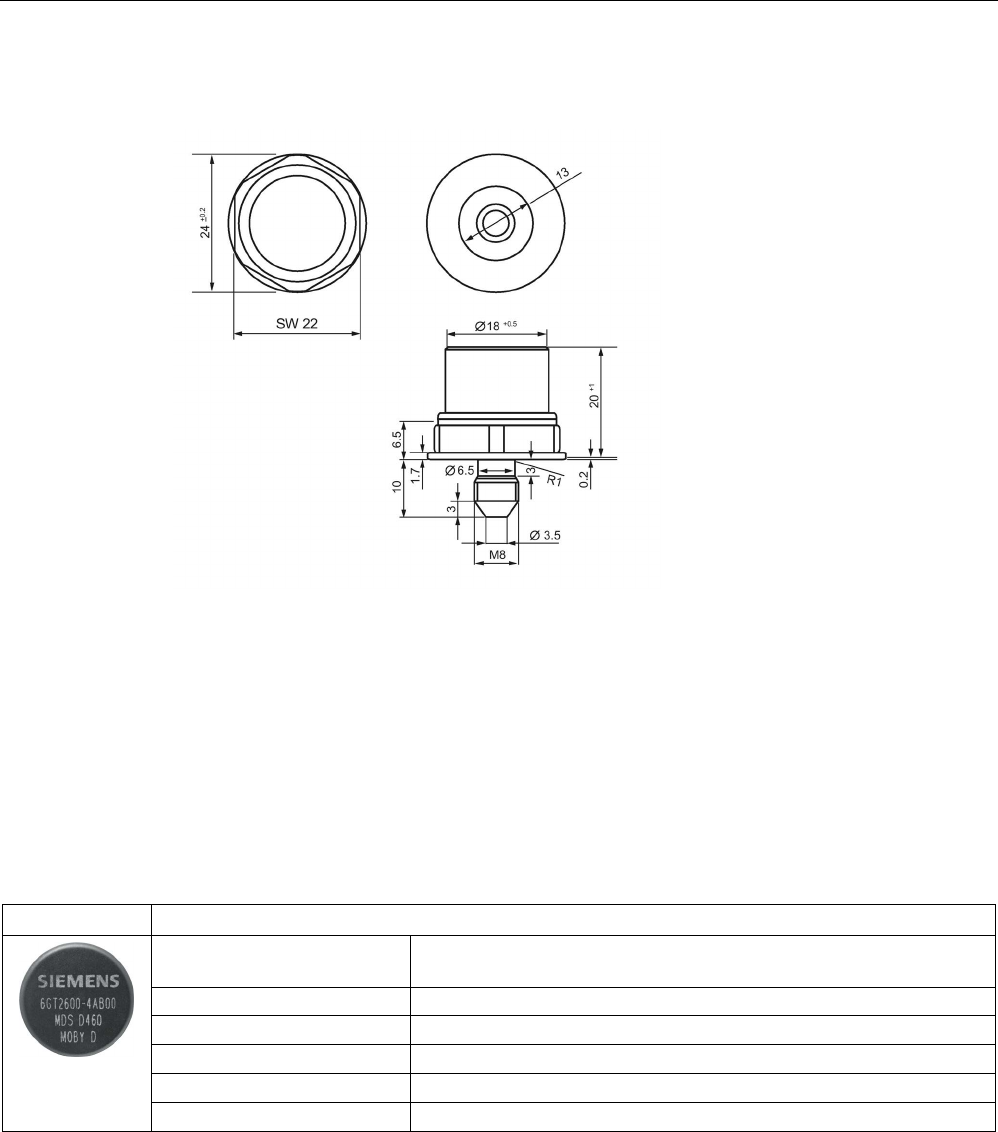
Dimension drawing
Dimensions in mm
Figure 8-55 Dimension drawing of MDS D428
8.22
MDS D460
8.22.1
Characteristics
MDS D460
Characteristics
Area of application Identification in small assembly lines; can also be used in a harsh in-
dustrial environment
Memory size
2000 bytes of FRAM user memory
Write/read range
See section "Field data of ISO transponders (MDS D) (Page 56).
Mounting on metal
Yes, with spacer
ISO standard
ISO 15693
Degree of protection
IP67/IPx9K
ISO transponder
8.22 MDS D460
SIMATIC RF300
System Manual, 07/2017, C79000-G8976-C345-07 365
8.22.2
Ordering data
Table 8- 54 Ordering data of MDS D460
Article number
MDS D460
6GT2600-4AB00
Table 8- 55 Ordering data of MDS D460 accessories
Article number
Spacer
6GT2690-0AG00
8.22.3
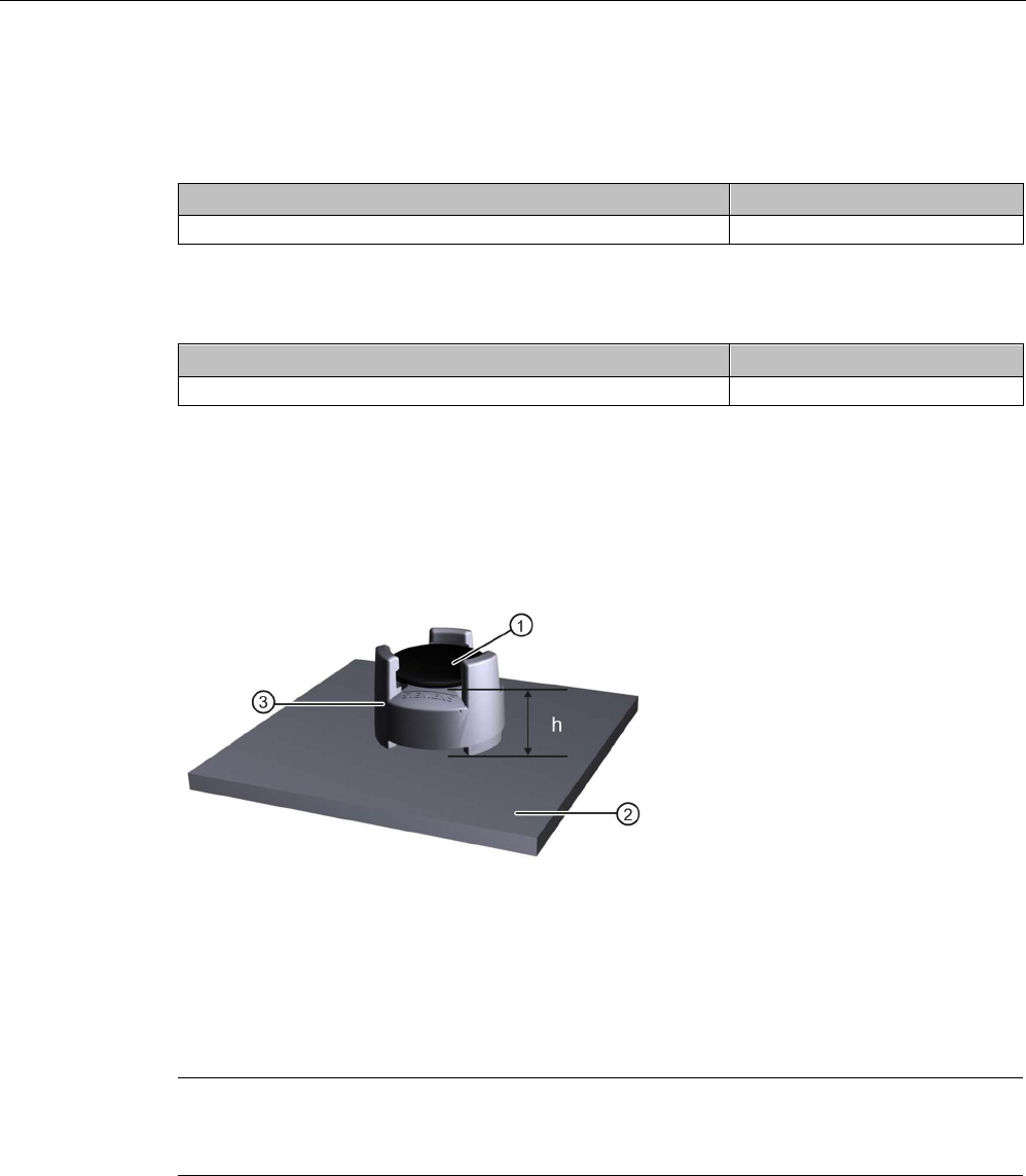
Mounting on metal
Mounting option on metal with spacer
①
Transponder
②
Metal
③
Spacer
h
≥ 10 mm
Figure 8-56 Mounting the MDS D460 on metal with spacer
Note
If the minimum guide values (h) are not observed, a reduction of the field data results.
In critical applications, it is recommended that a test is performed.
Flush-mounting
Flush-mounting of the MDS D460 in metal is not permitted!

ISO transponder
8.22 MDS D460
SIMATIC RF300
366 System Manual, 07/2017, C79000-G8976-C345-07
8.22.4
Technical specifications
Table 8- 56 Technical specifications for MDS D460
6GT2600-4AB00
Product type designation
SIMATIC MDS D460
Memory
Memory configuration
• UID • 8 bytes
• User memory • 2000 bytes FRAM
• OTP memory • 16 bytes FRAM
Read cycles (at < 40 ℃)
> 10
12
Write cycles (at < 40 ℃)
> 10
12
Data retention time (at < 40 ℃)
> 10 years
Write/read distance (Sg) Dependent on the reader used, see section "Field
data of ISO transponders (MDS D) (Page 56)"
MTBF (Mean Time Between Failures)
228 years
Mechanical specifications
Housing
• Material • Epoxy resin
• Color • Black
Recommended distance to metal
≥ 10 mm
Power supply
Inductive, without battery
Permitted ambient conditions
Ambient temperature
• during write/read access • -25 to +85 ℃
• outside the read/write field • -40 to +100 ℃
• during storage • -40 to +100 ℃
Degree of protection to EN 60529 • IP67
• IPx9K
steam jet: 150 mm; 10 to 15 l/min; 100 bar; 75
°C
Shock according to IEC 68-2-27
1)
500 m/s
2
Vibration according to IEC 68-2-6
1)
200 m/s
2
Torsion and bending load
Not permitted
Design, dimensions and weight
Dimensions (Ø x H)
16 x 3 mm
ISO transponder
8.22 MDS D460
SIMATIC RF300
System Manual, 07/2017, C79000-G8976-C345-07 367
6GT2600-4AB00
Weight
3 g
Type of mounting • Glued 2)
• With spacer
1)
The values for shock and vibration are maximum values and must not be applied continuously.
2) The processing instructions of the adhesive manufacturer must be observed.
8.22.5
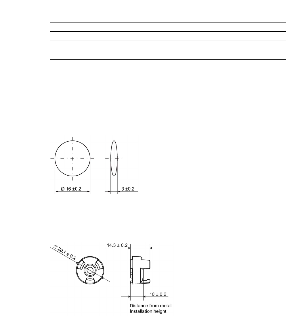
Dimension drawings
Dimensional drawing of MDS D460
Dimensions in mm
Figure 8-57 Dimensional drawing of MDS D460
Dimensional drawing of spacer
Dimensions in mm
Figure 8-58 Dimensional drawing of spacer
ISO transponder
8.23 MDS D521
SIMATIC RF300
368 System Manual, 07/2017, C79000-G8976-C345-07
8.23
MDS D521
8.23.1
Characteristics
MDS D521
Characteristics
Area of application The MDS D521 is designed for tool coding according to DIN
69873.
It can be used wherever small data carriers and exact positioning
are required, e.g. tool identification, workpiece holders.
The rugged housing of the MDS D521 means that it can also be
used in a harsh industrial environment without problems.
Memory size
8192 bytes of FRAM user memory
Write/read range
See section "Field data of ISO transponders (MDS D) (Page 56)"
Mounting on metal
Yes, flush-mounted in metal
ISO standard
ISO 15693
Degree of protection
IP67/IPx9K
8.23.2
Ordering data
Table 8- 57 Ordering data for MDS D521
Article number
MDS D521
6GT2600-5AE00
8.23.3
Mounting on metal
Mounting on metal
Figure 8-59 Mounting of MDS D421/D521/E623 on metal
ISO transponder
8.23 MDS D521
SIMATIC RF300
System Manual, 07/2017, C79000-G8976-C345-07 369
Flush-mounting
Figure 8-60 Mounting of MDS D421/D521/E623 in metal
Flush-mounting of the MDS in metal with tools
Figure 8-61 Flush-mounting of MDS D421/D521/E623 in metal with tools
b1
0.5 x 45°
b2
0.3 x 45° or R0.3
d
1
10 (-0.04... -0.13)
d
2
10 (+0.09... 0)
t1
4.5 (-0 ... -0.1)
t2
4.6 (+0.2 ... 0)
All dimensions in mm
Note
Installation instruction
The MDS should not protrude out of the locating hole; it must be flush with the outside
contour.
The mounting
instructions of the MDS and the conditions associated with the application
(e.g. peripheral speed, temperature, and use of coolant) must be observed during the
installation.
ISO transponder
8.23 MDS D521
SIMATIC RF300
370 System Manual, 07/2017, C79000-G8976-C345-07
Mounting information for adhesion
● Drill installation hole
● The adhesive surfaces must be dry, free from dust, oil, stripping agents and other
impurities
● Apply adhesive according to the manufacturer's processing instructions
● Press in transponder using your fingers; with antenna side to the outside (see figure
above)
● Remove residues of adhesive
● Allow to cure according to the manufacturer's instructions
● Flush-mounting of the transponder in metal with tools
Installation examples
Figure 8-62 Installation example of MDS D421/D521/E623 in a steep cone
Figure 8-63 Installation example of MDS D421/D521/E623 in a stud bolt
8.23.4
Technical specifications
Table 8- 58 Technical specifications for MDS D521
6GT2600-5AE00
Product type designation
SIMATIC MDS D521
Memory
Memory configuration
• UID • 8 bytes
• User memory • 8192 bytes FRAM

ISO transponder
8.23 MDS D521
SIMATIC RF300
System Manual, 07/2017, C79000-G8976-C345-07 371
6GT2600-5AE00
Read cycles (at < 40 ℃)
> 10
12
Write cycles (at < 40 ℃)
> 10
12
Data retention time (at < 40 ℃)
> 10 years
Write/read distance (Sg) Dependent on the reader used, see section "Field
data of ISO transponders (MDS D) (Page 56)"
MTBF (Mean Time Between Failures)
228 years
Mechanical specifications
Housing
• Material • Epoxy resin
• Color • Black
Recommended distance to metal
≥ 0 mm
Power supply
Inductive, without battery
Permitted ambient conditions
Ambient temperature
• during write/read access • -25 to +85 ℃
• outside the read/write field • -40 to +100 ℃
• during storage • -40 to +100 ℃
Degree of protection to EN 60529 • IP67
• IPx9K
steam jet: 150 mm; 10 to 15 l/min; 100 bar; 75
°C
Shock according to EN 60721-3-7 Class 7M3
1)
1000 m/s
2
Vibration according to EN 60721-3-7 Class 7M3
1)
200 m/s
2
Torsion and bending load
Not permitted
Design, dimensions and weight
Dimensions (Ø x H)
10 x 4.5 mm
Weight
1 g
Type of mounting
Glued
2)
1)
The values for shock and vibration are maximum values and must not be applied continuously.
2) The processing instructions of the adhesive manufacturer must be observed.
ISO transponder
8.24 MDS D522
SIMATIC RF300
372 System Manual, 07/2017, C79000-G8976-C345-07
8.23.5
Dimension drawing
Figure 8-64 Dimension drawing of MDS D521
All dimensions in mm
8.24
MDS D522
8.24.1
Characteristics
MDS D522
Characteristics
Area of application Identification of metallic workpiece holders, work-
pieces or containers
Memory size 8192 bytes of FRAM user memory
Write/read range See "Field data of ISO transponders (MDS D)
(Page 56)."
Mounting in metal
Yes
ISO standard
ISO 15693
Degree of protection
IP68
8.24.2
Ordering data
Table 8- 59 Ordering data for MDS D522
Article number
MDS D522
Units in a package: 10 units
A mounting aid is included in the scope of supply per packaging
unit.
6GT2600-5AF00
ISO transponder
8.24 MDS D522
SIMATIC RF300
System Manual, 07/2017, C79000-G8976-C345-07 373
8.24.3
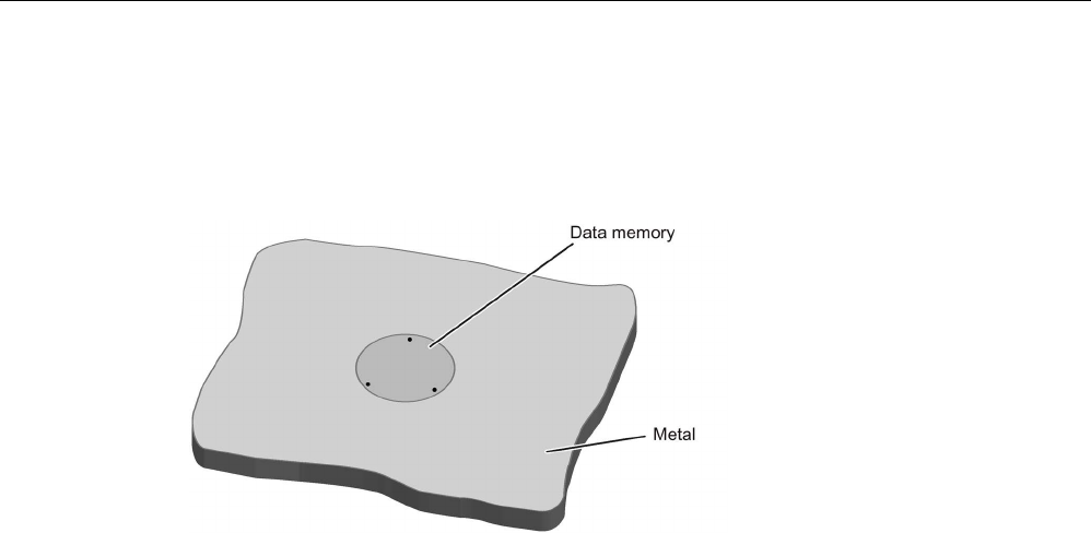
Mounting in metal
Flush-mounting
Figure 8-65 Mounting of MDS D522 in metal
Mounting information for screws
You can screw the transponder into a pre-drilled threaded hole using the screw-in aid.
Mounting information for adhesion
● Drill installation hole
● The adhesive surfaces must be dry, free from dust, oil, stripping agents and other
impurities
● Apply adhesive according to the manufacturer's processing instructions
● Press in MDS D522 using your fingers; with antenna to the outside
● Remove residues of adhesive
● Allow to cure according to the manufacturer's instructions
● Flush-mounting of MDS D522 in metal with tools
8.24.4
Technical specifications
Table 8- 60 Technical specifications for MDS D522
6GT2600-5AF00
Product type designation
SIMATIC MDS D522
Memory
Memory configuration

ISO transponder
8.24 MDS D522
SIMATIC RF300
374 System Manual, 07/2017, C79000-G8976-C345-07
6GT2600-5AF00
• UID • 8 bytes
• User memory • 8192 bytes FRAM
Read cycles (at < 40 ℃)
> 10
12
Write cycles (at < 40 ℃)
> 10
12
Data retention time (at < 40 ℃)
> 10 years
Write/read distance (Sg) Dependent on the reader used, see section "Field
data of ISO transponders (MDS D) (Page 56)"
MTBF (Mean Time Between Failures)
285 years
Mechanical specifications
Housing
• Material • Plastic PA 6.6 GF; brass nickel plated
• Color • Black/silver
Recommended distance to metal
≥ 0 mm
Power supply
Inductive, without battery
Permitted ambient conditions
Ambient temperature
• during write/read access • -25 to +85 ℃
• outside the read/write field • -40 to +100 ℃
• during storage • -40 to +100 ℃
Degree of protection to EN 60529 IP68
2 hours, 2 bar, +20 °C
Shock according to EN 60721-3-7 Class 7M3
1)
500 m/s
2
Vibration according to EN 60721-3-7 Class 7M3
1)
200 m/s
2
Torsion and bending load
Not permitted
Design, dimensions and weight
Dimensions (Ø x H)
20 x 6 mm
Weight 13 g
Type of mounting • Glued 2)
• 1 x transponder thread M20
≤ 1 Nm
1)
The values for shock and vibration are maximum values and must not be applied continuously.
2) The processing instructions of the adhesive manufacturer must be observed.
ISO transponder
8.25 MDS D522 special variant
SIMATIC RF300
System Manual, 07/2017, C79000-G8976-C345-07 375
8.24.5
Dimension drawing
Figure 8-66 Dimensional drawing of MDS D522
All dimensions in mm
8.25
MDS D522 special variant
8.25.1
Characteristics
MDS D522 special version
Characteristics
Area of application Identification of metallic workpiece holders or work-
pieces
Memory size
8192 bytes of FRAM user memory
Write/read range See "Field data of ISO transponders (MDS D)
(Page 56)."
Mounting in metal
Yes
ISO standard
ISO 15693
Degree of protection IP68
8.25.2
Ordering data
Table 8- 61 MDS D522 special version
Article number
MDS D522 special version
Units in a package: 10 units
A mounting aid is included in the scope of supply per packaging
unit.
6GT2600-5AF00-0AX0
ISO transponder
8.25 MDS D522 special variant
SIMATIC RF300
376 System Manual, 07/2017, C79000-G8976-C345-07
8.25.3
Mounting in metal
Flush-mounting
Figure 8-67 Flush installation of the MDS D522 special version in metal without clearance
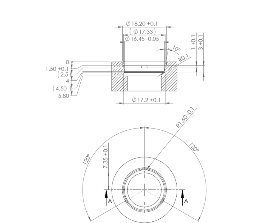
8.25.4
Installation instructions
The transponder MDS D522 special version is designed to be mounted once.
Note the following instructions when mounting the MDS D522 in a workpiece to avoid
damaging the transponder:
● Prepare the workpiece according to the following drawing.
● Using the accompanying mounting aid, press the transponder with uniform and evenly
distributed pressure into the drilled hole until the transponder locks in place. Make sure
that the transponder does not become tilted.
ISO transponder
8.25 MDS D522 special variant
SIMATIC RF300
System Manual, 07/2017, C79000-G8976-C345-07 377
Figure 8-68 Dimension drawing: Workpiece drill hole for mounting the MDS D522 special version

ISO transponder
8.25 MDS D522 special variant
SIMATIC RF300
378 System Manual, 07/2017, C79000-G8976-C345-07
8.25.5
Technical specifications
Table 8- 62 Technical data of MDS D522 special version
6GT2600-5AF00-0AX0
Product type designation
SIMATIC MDS D522 special version
Memory
Memory configuration
• UID • 8 bytes
• User memory • 8192 bytes FRAM
Read cycles (at < 40 ℃)
> 10
12
Write cycles (at < 40 ℃)
> 10
12
Data retention time (at < 40 ℃)
> 10 years
Write/read distance (Sg) Dependent on the reader used, see section "Field
data of ISO transponders (MDS D) (Page 56)"
MTBF (Mean Time Between Failures)
228 years
Mechanical specifications
Housing
• Material • Plastic PA 6.6 GF
• Color • Black
Recommended distance to metal
≥ 0 mm
Power supply
Inductive, without battery
Permitted ambient conditions
Ambient temperature
• during write/read access • -25 to +85 ℃
• outside the read/write field • -40 to +100 ℃
• during storage • -40 to +100 ℃
Degree of protection to EN 60529 IP68
2 hours, 2 bar, +20 °C
Shock according to EN 60721-3-7 Class 7M3
1)
500 m/s
2
Vibration according to EN 60721-3-7 Class 7M3
1)
200 m/s
2
Torsion and bending load Not permitted
Design, dimensions and weight
Dimensions (Ø x H) 18 (+0.1) × 5.2 mm
Weight
Approx. 1.2 g
Type of mounting
Clipping in once (with accompanying tool)
1) The values for shock and vibration are maximum values and must not be applied continuously.
ISO transponder
8.25 MDS D522 special variant
SIMATIC RF300
System Manual, 07/2017, C79000-G8976-C345-07 379
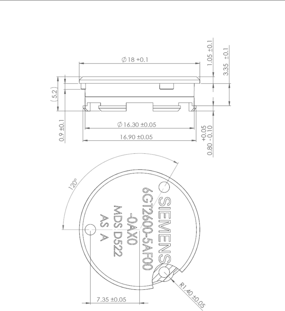
8.25.6
Dimensional drawing
Figure 8-69 Dimension drawing MDS D522 special version
All dimensions in mm
ISO transponder
8.26 MDS D524
SIMATIC RF300
380 System Manual, 07/2017, C79000-G8976-C345-07
8.26
MDS D524
8.26.1
Characteristics
MDS D524
Characteristics
Area of application Production and distribution logistics as well as in assem-
bly and production lines,
can also be used in a harsh industrial environment without
problem
Memory size
8192 bytes of FRAM user memory
Write/read range See section "Field data of ISO transponders (MDS D)
(Page 56)."
Mounting on metal
Yes, with spacer
ISO standard
ISO 15693
Degree of protection
IP67; IPx9K
8.26.2
Ordering data
Table 8- 63 Ordering data for MDS D524
Article number
MDS D524
6GT2600-5AC00
Table 8- 64 Ordering data of MDS D524 accessories
Article number
Spacer
6GT2690-0AK00
ISO transponder
8.26 MDS D524
SIMATIC RF300
System Manual, 07/2017, C79000-G8976-C345-07 381
8.26.3
Mounting on metal
Mounting on metal
h
≥ 15 mm
Figure 8-70 Mounting the MDS D124/D324/D424/D524/E624 and RF320T on metal with spacer
Flush-mounting
h
≥ 15 mm
a
≥ 25 mm
Figure 8-71 Flush-mounting of the MDS D124/D324/D424/D524/E624 and RF320T in metal with
spacer

ISO transponder
8.26 MDS D524
SIMATIC RF300
382 System Manual, 07/2017, C79000-G8976-C345-07
Note
Going below the distances
If the distances (a and h) are not observed, a reduction of the field data
results. It is possible
to mount the MDS with metal screws (M3 countersunk head screws). This has no tangible
impact on the range.
8.26.4
Technical specifications
Table 8- 65 Technical specifications for MDS D524
6GT2600-5AC00
Product type designation
SIMATIC MDS D524
Memory
Memory configuration
• UID • 8 bytes
• User memory • 8192 bytes FRAM
Read cycles (at < 40 ℃)
> 10
12
Write cycles (at < 40 ℃)
> 10
12
Data retention time (at < 40 ℃)
> 10 years
Write/read distance (Sg) Dependent on the reader used, see section "Field
data of ISO transponders (MDS D) (Page 56)"
MTBF (Mean Time Between Failures)
228 years
Mechanical specifications
Housing
• Material • Epoxy resin
• Color • Black
Recommended distance to metal
≥ 15 mm
Power supply
Inductive, without battery
Permitted ambient conditions
Ambient temperature
• during write/read access • -25 to +85 ℃
• outside the read/write field • -40 to +100 ℃
• during storage • -40 to +100 ℃
ISO transponder
8.26 MDS D524
SIMATIC RF300
System Manual, 07/2017, C79000-G8976-C345-07 383
6GT2600-5AC00
Degree of protection to EN 60529 • IP67
• IPx9K
Shock according to EN 60721-3-7 Class 7M3
1)
1000 m/s
2
Vibration according to EN 60721-3-7 Class 7M3
1)
200 m/s
2
Torsion and bending load
Not permitted
Design, dimensions and weight
Dimensions (Ø x H)
27 x 4 mm
Weight
5 g
Type of mounting • Glued 2)
• 1x screw M3 3)
≤ 1 Nm
1)
The values for shock and vibration are maximum values and must not be applied continuously.
2)
The processing instructions of the adhesive manufacturer must be observed.
3 ) To prevent it loosening during operation, secure the screw with screw-locking varnish.
8.26.5
Dimension drawing
Figure 8-72 Dimensional drawing of MDS D524
All dimensions in mm
ISO transponder
8.27 MDS D525
SIMATIC RF300
384 System Manual, 07/2017, C79000-G8976-C345-07
8.27
MDS D525
8.27.1
Characteristics
MDS D525
Characteristics
Area of application Compact and rugged ISO transponder; suitable for screw
mounting
Use in assembly and production lines in the powertrain
sector; ideal for mounting on motors, gearboxes, and work-
piece holders
Rugged packaging of the MDS D525; can therefore also be
used under extreme environmental conditions without prob-
lems
Memory size
8192 bytes of FRAM user memory
Write/read range See section "Field data of ISO transponders (MDS D)
(Page 56)".
Mounting on metal
Yes
ISO standard
ISO 15693
Degree of protection
IP68/IPx9K
8.27.2
Ordering data
Table 8- 66 Ordering data for MDS D525
Article number
MDS D525
6GT2600-5AG00
ISO transponder
8.27 MDS D525
SIMATIC RF300
System Manual, 07/2017, C79000-G8976-C345-07 385
8.27.3
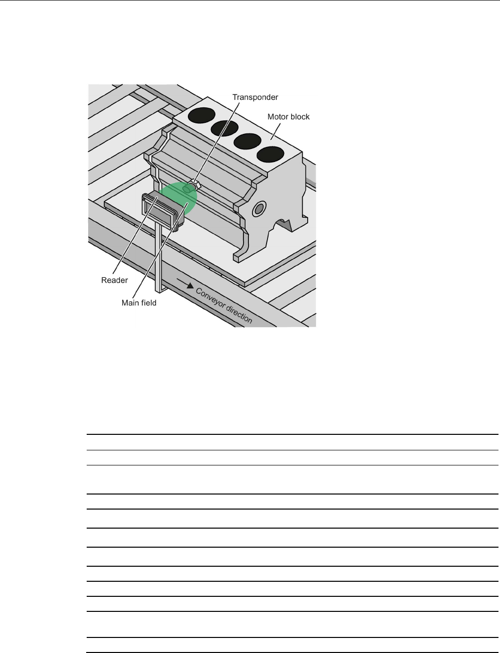
Application example
Figure 8-73 Application example
8.27.4
Technical specifications
Table 8- 67 Technical specifications for MDS D525
6GT2600-5AG00
Product type designation SIMATIC MDS D525
Memory
Memory configuration
• UID • 8 bytes
• User memory • 8192 bytes FRAM
• OPT memory • 16 bytes FRAM
Read cycles (at < 40 ℃) > 1012
Write cycles (at < 40 ℃)
> 10
12
Data retention time (at < 40 ℃)
> 10 years
Write/read distance (Sg) Dependent on the reader used, see section "Field
data of ISO transponders (MDS D) (Page 56)"
MTBF (Mean Time Between Failures)
228 years

ISO transponder
8.27 MDS D525
SIMATIC RF300
386 System Manual, 07/2017, C79000-G8976-C345-07
6GT2600-5AG00
Mechanical specifications
Enclosure
• Material • Plastic PA 6.6 GF
• Color • Black
Recommended distance to metal
> 0 mm
Power supply
Inductive, without battery
Permitted ambient conditions
Ambient temperature
• during write/read access • -25 to +85 ℃
• outside the read/write field • -40 to +125 ℃
• during storage • -40 to +125 ℃
Degree of protection to EN 60529 • IP68
2 hours, 2 bar, +20 °C
• IPx9K
steam jet: 150 mm; 10 to 15 l/min; 100 bar; 75
°C
Shock-resistant to IEC 68-2-27
1)
500 m/s
2
Vibration-resistant to IEC 68-2-6
1)
200 m/s
2
Torsion and bending load
Not permitted
Design, dimensions and weights
Dimensions (Ø x H)
24 x 10 mm (without set screw)
Weight
35 g
Type of mounting 1x transponder set screw M6
SW 22; ≤ 6 Nm
1) The values for shock and vibration are maximum values and must not be applied continuously.
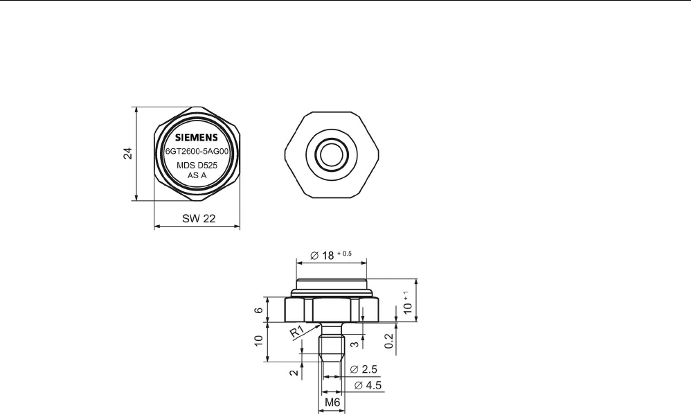
ISO transponder
8.27 MDS D525
SIMATIC RF300
System Manual, 07/2017, C79000-G8976-C345-07 387
8.27.5
Dimension drawing
Figure 8-74 Dimensional drawing of MDS D525
All dimensions in mm
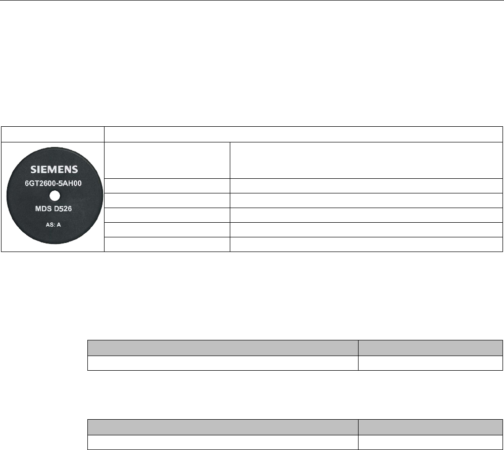
ISO transponder
8.28 MDS D526
SIMATIC RF300
388 System Manual, 07/2017, C79000-G8976-C345-07
8.28
MDS D526
8.28.1
Characteristics
MDS D526
Characteristics
Area of application Compact and rugged ISO transponder; suitable for identification
of transport units in production-related logistics; can also be de-
ployed in harsh conditions
Memory size 8192 bytes of FRAM user memory
Write/read range
See section "Field data of ISO transponders (MDS D) (Page 56)."
Mounting on metal
Yes, with spacer
ISO standard
ISO 15693
Degree of protection
IP68
8.28.2
Ordering data
Table 8- 68 Ordering data for MDS D526
Article number
MDS D526
6GT2600-5AH00
Table 8- 69 Ordering data for MDS D526 accessories
Article number
Spacer
6GT2690-0AL00
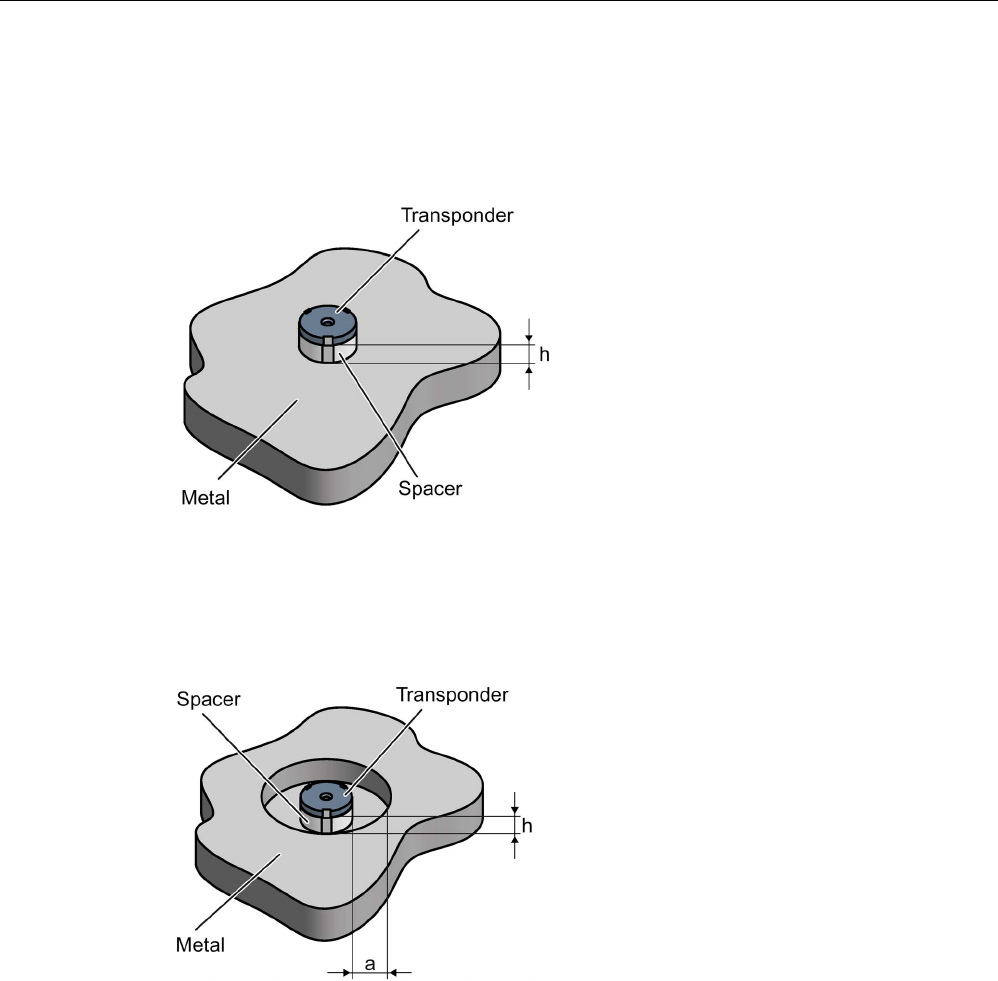
ISO transponder
8.28 MDS D526
SIMATIC RF300
System Manual, 07/2017, C79000-G8976-C345-07 389
8.28.3
Mounting on metal
Mounting on metal
h
≥ 25 mm
Figure 8-75 Mounting the MDS D126 / D426 / D526 on metal with spacer
Flush-mounted in metal
h
≥ 25 mm
a
≥ 50 mm
Figure 8-76 Flush installation of the MDS D126 / D426 / D526 in metal with spacer

ISO transponder
8.28 MDS D526
SIMATIC RF300
390 System Manual, 07/2017, C79000-G8976-C345-07
8.28.4
Technical specifications
Table 8- 70 Technical specifications for MDS D526
6GT2600-5AH00
Product type designation
SIMATIC MDS D526
Memory
Memory configuration
• UID • 8 bytes
• User memory • 8192 bytes FRAM
• OTP • 32 bytes
Read cycles (at < 40 ℃)
> 10
12
Write cycles (at < 40 ℃)
> 10
12
Data retention time (at < 40 ℃)
> 10 years
Write/read distance (Sg) Dependent on the reader used, see section "Field
data of ISO transponders (MDS D) (Page 56)"
MTBF (Mean Time Between Failures)
228 years
Mechanical specifications
Housing
• Material • Plastic PA 6.6 GF
• Color • Black
Recommended distance to metal
≥ 25 mm
Power supply
Inductive, without battery
Permitted ambient conditions
Ambient temperature
• during write/read access • -25 to +85 ℃
• outside the read/write field • -40 to +100 ℃
• during storage • -40 to +100 ℃
Degree of protection to EN 60529 IP68
2 hours, 2 bar, +20 °C
Shock according to IEC 68-2-27
1)
500 m/s
2
Vibration according to IEC 68-2-6
1)
200 m/s
2
Torsion and bending load
Not permitted
Design, dimensions and weight
Dimensions (Ø x H)
50 x 3.6 mm
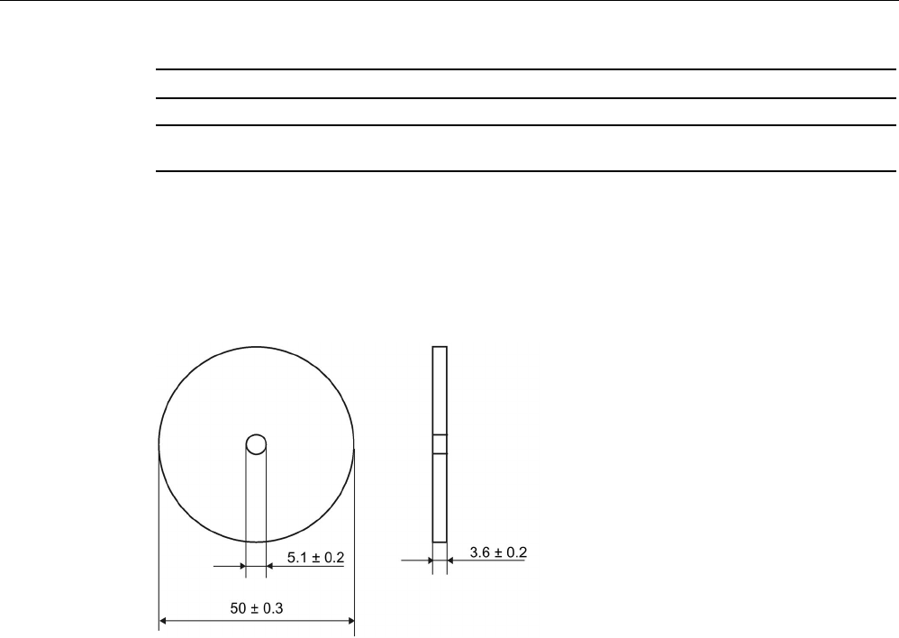
ISO transponder
8.28 MDS D526
SIMATIC RF300
System Manual, 07/2017, C79000-G8976-C345-07 391
6GT2600-5AH00
Weight
13 g
Type of mounting 1 x M4 screw 2)
≤ 1 Nm
1)
The values for shock and vibration are maximum values and must not be applied continuously.
2 ) To prevent it loosening during operation, secure the screw with screw locking varnish.
8.28.5
Dimension drawing
Figure 8-77 Dimensional drawing of MDS D526
All dimensions in mm
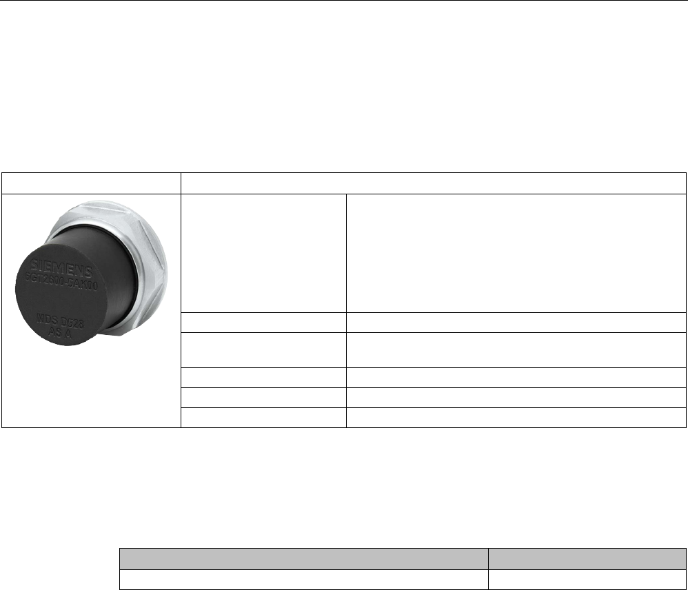
ISO transponder
8.29 MDS D528
SIMATIC RF300
392 System Manual, 07/2017, C79000-G8976-C345-07
8.29
MDS D528
8.29.1
Characteristics
MDS D528
Characteristics
Area of application Compact and rugged ISO transponder; suitable for screw
mounting
Use in assembly and production lines in the powertrain
sector
The rugged housing of the MDS D528 means that it can
also be used in extreme environmental conditions without
problems.
Memory size
8192 bytes of FRAM user memory
Write/read range See section "Field data of ISO transponders (MDS D)
(Page 56)"
Mounting on metal
Yes
ISO standard
ISO 15693
Degree of protection
IP68/IPx9K
8.29.2
Ordering data
Table 8- 71 Ordering data for MDS D528
Article number
MDS D528
6GT2600-5AK00
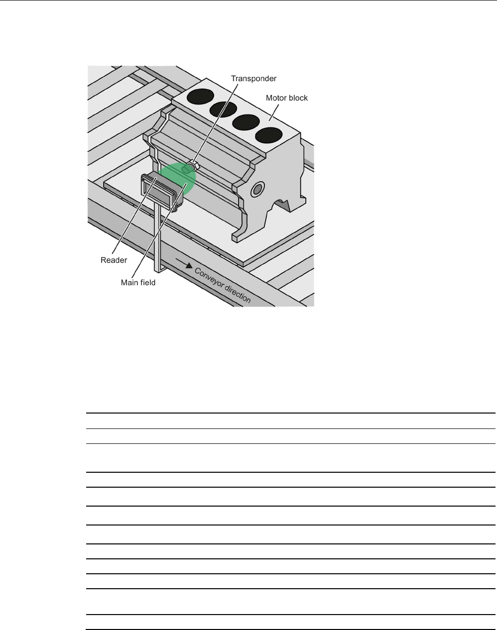
ISO transponder
8.29 MDS D528
SIMATIC RF300
System Manual, 07/2017, C79000-G8976-C345-07 393
8.29.3
Application example
Figure 8-78 Application example
8.29.4
Technical specifications
Table 8- 72 Technical specifications for MDS D528
6GT2600-5AK00
Product type designation SIMATIC MDS D528
Memory
Memory configuration
• UID • 8 bytes
• User memory • 8192 bytes FRAM
• OTP • 32 bytes
Read cycles (at < 40 ℃) > 1012
Write cycles (at < 40 ℃)
> 10
12
Data retention time (at < 40 ℃)
> 10 years
Write/read distance (Sg) Dependent on the reader used, see section "Field
data of ISO transponders (MDS D) (Page 56)"
MTBF (Mean Time Between Failures)
228 years

ISO transponder
8.29 MDS D528
SIMATIC RF300
394 System Manual, 07/2017, C79000-G8976-C345-07
6GT2600-5AK00
Mechanical specifications
Housing
• Material • Plastic PA 6.6 GF
• Color • Black
Recommended distance to metal
≥ 0 mm
Power supply
Inductive, without battery
Permitted ambient conditions
Ambient temperature
• during write/read access • -25 to +85 ℃
• outside the read/write field • -40 to +125 ℃
• during storage • -40 to +125 ℃
Degree of protection to EN 60529 • IP68
2 hours, 2 bar, +20 °C
• IPx9K
steam jet: 150 mm; 10 to 15 l/min; 100 bar; 75
°C
Shock according to IEC 68-2-27
1)
500 m/s
2
Vibration according to IEC 68-2-6
1)
200 m/s
2
Torsion and bending load
Not permitted
Design, dimensions and weight
Dimensions (Ø x H)
24 x 20 mm (without set screw)
Weight
35 g
Type of mounting 1x transponder set screw M8
SW 22; ≤ 8 Nm
1) The values for shock and vibration are maximum values and must not be applied continuously.
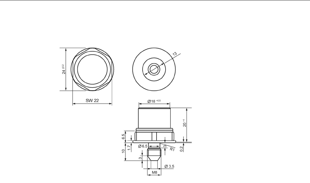
ISO transponder
8.29 MDS D528
SIMATIC RF300
System Manual, 07/2017, C79000-G8976-C345-07 395
8.29.5
Dimension drawing
Figure 8-79 Dimensional drawing of MDS D528
All dimensions in mm

ISO transponder
8.29 MDS D528
SIMATIC RF300
396 System Manual, 07/2017, C79000-G8976-C345-07

SIMATIC RF300
System Manual, 07/2017, C79000-G8976-C345-07 397
System integration
9
The communication modules (interface modules) are links between the RFID components
(reader and transponder) and the higher-level controllers (e.g. SIMATIC S7), or PCs or
computers.
9.1
Introduction
The readers are connected to the controller via the following interface or communications
modules:
● ASM 456
● ASM 475
● SIMATIC RF120C
● SIMATIC RF160C
● SIMATIC RF170C
● SIMATIC RF180C
● SIMATIC RF182C
● RFID 181EIP
Function blocks, interface modules/communication modules and readers
Function blocks are used for integration into the SIMATIC. You will find information on the
following blocks on the Internet in "Industry Online Support
(https://support.industry.siemens.com/cs/ww/en/ps/14971)".
● Ident profile and Ident blocks, standard function for RFID systems
The Ident library linked into the TIA Portal as of STEP 7 Basic / Professional V14 SP 1
● RFID standard profile; standard functions for RFID systems
● FB 45 for MOBY U, MOBY D, RF200, RF300
● FB 55
● RF160C communications module with FC 44

System integration
9.1 Introduction
SIMATIC RF300
398 System Manual, 07/2017, C79000-G8976-C345-07
Interface modules/communication modules and function blocks
The following table shows the most important characteristics of the interface
modules/communications modules.
Table 9- 1 Overview of interface modules/communication modules
ASM/
communications
module
Interfaces to the
application
(PLC)
Interfaces to the
reader
Reader con-
nections
Dimensions
(W x H x D)
Temperature
range
Degree of
protection
ASM 456 PROFIBUS DP-
V1
2 x 8-pin connector
socket, M12
2 (parallel) 60 x 210 x 54
or 79 mm
0 ℃ to +55
℃
IP67
ASM 475 S7-300 (cen-
tral), ET200M
(PROFIBUS)
Via screw terminals
in front connector
2 (parallel) 40 x 125 x 120 mm 0 ℃ to +60
℃
IP20
SIMATIC
RF120C
S7-1200 (cen-
tral)
9-pin D-sub socket 1 30 x 100 x 75 mm 0 ℃ to +55
℃
IP20
SIMATIC
RF160C
PROFIBUS DP
/ DP-V0
2 x 8-pin connector
socket, M12
2 (parallel) 60 x 210 x 30 mm 0 ℃ to +55
℃
IP67
SIMATIC
RF170C
PROFIBUS DP-
V1
PROFINET IO
2 x 8-pin connector
socket, M12
2 (parallel) 90 x 130 x 60 mm -25 °C to
+55 °C
IP67
SIMATIC
RF180C
PROFINET IO 2 x 8-pin connector
socket, M12
2 (parallel) 60 x 210 x 54 mm 0 °C to
+60° C
IP67
SIMATIC
RF182C
TCP/IP 2 x 8-pin connector
socket, M12
2 (parallel) 60 x 210 x 30 mm 0 ℃ to +60
℃
IP67
RFID 181EIP Ethernet IP 2 x 8-pin connector
socket, M12
2 (parallel) 60 x 210 x 54 mm 0 °C to
+60° C
IP67
The following table shows the program blocks compatible with the interface
modules/communications modules.
Table 9- 2 Compatible program blocks
ASM/
communications mod-
ule
Compatible program blocks in conjunction with ...
S7-300 / S7-400 and
STEP 7 Classic V5.5
S7-300 / S7-400 and
STEP 7 Basic/Professional
S7-1200 / S7-1500 and
STEP 7 Basic/Professional
ASM 456
FB 45
FB 55
FC 56
Standard profile V1.19
Ident profile
FB 45
FB 55
FC 56
Ident profile
Ident blocks
Ident profile
Ident blocks
PIB_1200_UID_001KB
PIB_1200_UID_032KB
ASM 475
FB 45
FB 55
FB 45
FB 55
--
SIMATIC RF120C
-- -- Ident profile
Ident blocks
PIB_1200_UID_001KB
PIB_1200_UID_032KB
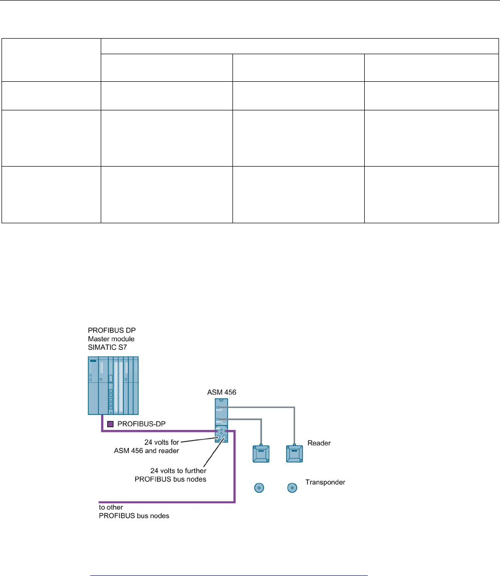
System integration
9.2 ASM 456
SIMATIC RF300
System Manual, 07/2017, C79000-G8976-C345-07 399
ASM/
communications mod-
ule
Compatible program blocks in conjunction with ...
S7-300 / S7-400 and
STEP 7 Classic V5.5
S7-300 / S7-400 and
STEP 7 Basic/Professional
S7-1200 / S7-1500 and
STEP 7 Basic/Professional
SIMATIC RF160C
FC 44
Application blocks for RF160C
FC 44
Application blocks for RF160C
Application blocks for RF160C
SIMATIC RF170C
FB 45
FB 55
FB 45
FB 55
Ident profile
Ident blocks
PIB_1200_UID_001KB
PIB_1200_UID_032KB
SIMATIC RF180C
FB 45
FB 55
Standard profile V1.19
Ident profile
FB 45
FB 55
Ident profile
Ident blocks
Ident profile
Ident blocks
PIB_1200_UID_001KB
PIB_1200_UID_032KB
9.2
ASM 456
Configured with ASM 456
Figure 9-1 Configuration of ASM 456
For more detailed information, please refer to ASM 456 Operating Instructions
(https://support.industry.siemens.com/cs/ww/en/view/32629442).
System integration
9.3 ASM 475
SIMATIC RF300
400 System Manual, 07/2017, C79000-G8976-C345-07
9.3
ASM 475
9.3.1
Features
Area of application
The ASM 475 interface module acting as the link between all RF300 systems and SIMATIC
S7-300 performs the functions of a communication module. It can be operated centrally in
the S7-300 or decentrally in an ET200M.
As many as eight ASM 475 interface modules can be plugged into one SIMATIC S7-300
rack and operated. In a configuration with several racks (max. four), the ASM 475 can be
plugged into and operated on any rack. This means that as many as 32 ASMs can be
operated in the maximum configuration of a SIMATIC S7-300. The ASM can also be
operated in the ET 200M distributed I/O on PROFIBUS. Operation in an S7-400 environment
is therefore problem-free. Up to 7 ASMs can be operated on each ET 200M.
Error messages and operating statuses are indicated by LEDs.
Since there is electrical isolation between the read/write device and the SIMATIC S7-300
bus, a configuration that is immune to interference is possible.
Figure 9-2 Interface module ASM 475
The ASM 475 with the article number 6GT2002-0GA10 is a module that can be set in the
parameters. The basic functions of the module are then already specified when the module
is configured in HW Config (e.g. standard addressing).
The data in the MDS is accessed direct by means of physical addresses using the ASM 475.
Operation in a SIMATIC S7 is controlled by the function block FB 45.
ASM 475 and FB 45 form a unit that is used for reading the data of the MDS simply and at
optimal speed.

System integration
9.3 ASM 475
SIMATIC RF300
System Manual, 07/2017, C79000-G8976-C345-07 401
9.3.2
Ordering data
Table 9- 3 Ordering data for ASM 475
Article number
ASM 475 interface module for SIMATIC S7
2 x RF3xxR reader with RS-422 can be connected in paral-
lel, without front connector
6GT2002-0GA10
Table 9- 4 Ordering data for ASM 475 accessories
Article number
Front connector (1 x per ASM) 6ES7392-1AJ00-0AA0
Connecting cable ASM 475 ↔ RF3xxR
Plug-in cable, pre-assembled, length: 2 m (standard length)
6GT2891-0EH20
Plug-in cable, pre-assembled, length: 5 m
6GT2891-0EH50
Terminal element (1 x per reader cable)
6ES7390-5BA00-0AA0
Shield connecting element
6ES7390-5AA00-0AA0
The plug-in cables 6GT2891-4Fxx can be used as extension cables.
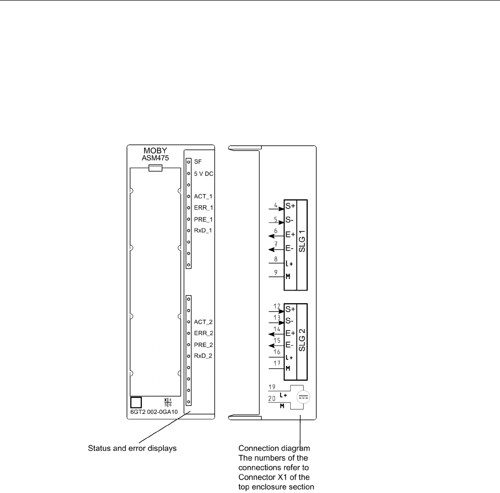
System integration
9.3 ASM 475
SIMATIC RF300
402 System Manual, 07/2017, C79000-G8976-C345-07
9.3.3
Indicators
Bezel and indicator elements
The figure below illustrates the bezel of the ASM 475 and the inside of the front door
complete with the associated connection diagram. The read/write devices must be
connected to the ASM in accordance with the connection diagram.
Figure 9-3 Bezel and inside of the front door of the ASM 475

System integration
9.3 ASM 475
SIMATIC RF300
System Manual, 07/2017, C79000-G8976-C345-07 403
Display elements on the ASM
Table 9- 5 Function of the LEDs on the ASM 475
Light emitting diode
Meaning
SF
System fault (hardware error on ASM)
DC 5V 24 V are connected to ASM and the 5 V voltage on ASM is OK.
ACT_1, ACT_2
The corresponding reader is active in processing a user command.
ERR_1, ERR_2 A flashing pattern indicates the last error to occur. This display can be reset
using the parameter Option 1.
PRE_1, PRE_2
Indicates the presence of a transponder.
RxD_1, RxD_2 Indicates live communication with the reader. In the event of a fault on the
reader, this display may also be lit.
On the ASM 475, further operating states are indicated with the LEDs PRE, ERR and SF:
Table 9- 6 Operating status display on ASM 475 via LEDs
SF
PRE_1
ERR_1
PRE_2
ERR_2
Meaning
ON OFF/ON ON
(perm.)
OFF/ON ON
(perm.)
Hardware is defective (RAM, Flash, etc.)
ON OFF ON OFF OFF Charger is defective (can only be repaired in
the factory).
OFF 2 Hz OFF 2 Hz OFF Firmware loading is active or no firmware
detected
• Firmware download
• ASM must not be switched off
OFF 2 Hz 2 Hz 2 Hz 2 Hz Firmware loading
terminated with errors
• Restart required
• Load firmware again
• Check update files
Any
value
5 Hz 5 Hz 5 Hz 5 Hz Operating system error
• Switch ASM off/on
OFF OFF 1 flash
every 2 s
OFF 1 flash
every 2 s
ASM has booted and is waiting for a RESET
(init_run) from the user.
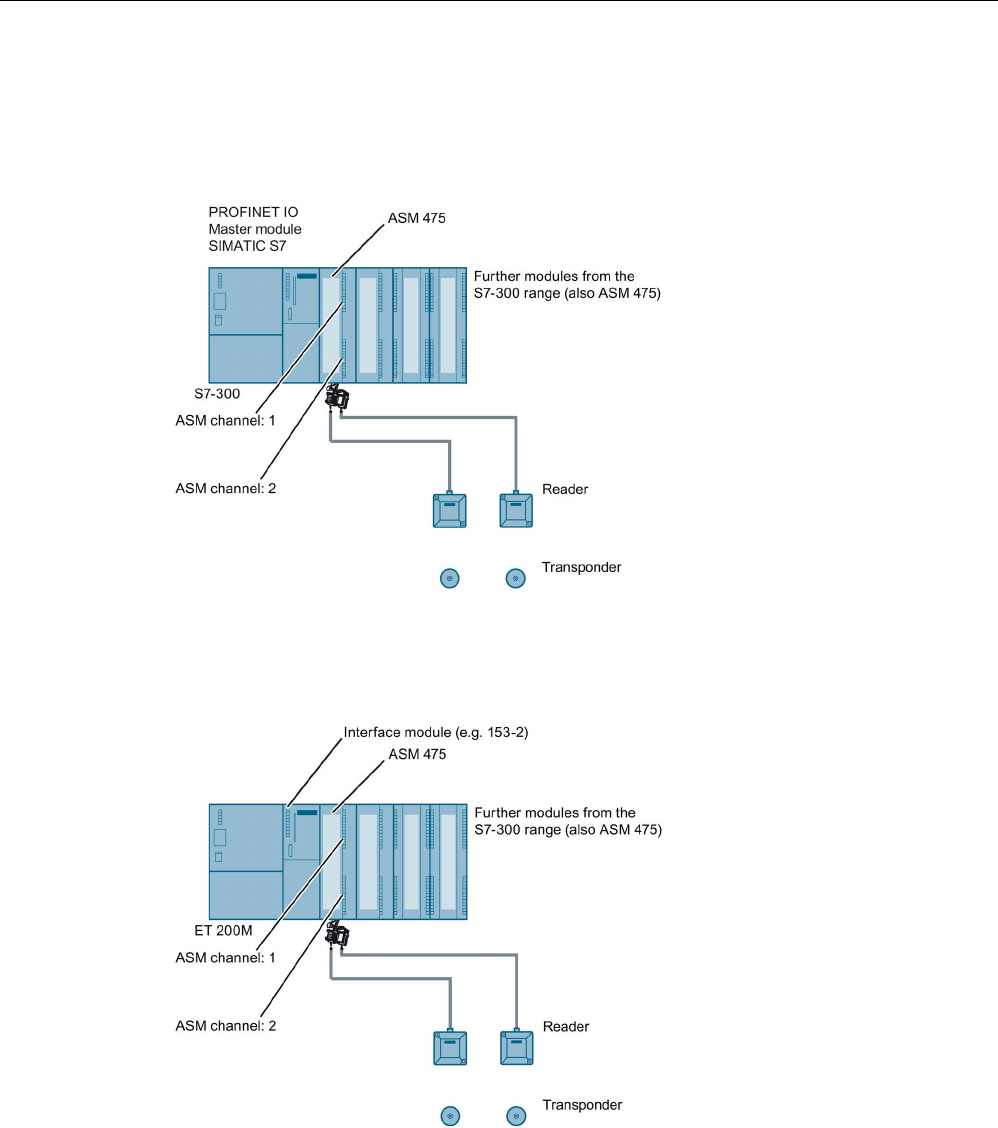
System integration
9.3 ASM 475
SIMATIC RF300
404 System Manual, 07/2017, C79000-G8976-C345-07
9.3.4
Configuration
Centralized configuration with SIMATIC S7-300
Figure 9-4 Configuration of ASM 475 central
Distributed configuration with ET200M
Figure 9-5 Configuration of ASM 475 distributed
Reader connection system
You will find more information on the reader connector technology in the section "Reader
RF3xxR (RS422) with ASM 475 (Page 438)".

System integration
9.3 ASM 475
SIMATIC RF300
System Manual, 07/2017, C79000-G8976-C345-07 405
Cable installation
Signal
Pin on
M12 connect-
or
Cable
Labeling
24 VDC 1 white 1 Reader 2
8 -16
TX - 2 brown 1 Reader 2
7-15
GND 3 Green 1 Reader 2
9-17
TX + 4 Yellow 1 Reader 2
6-14
RX + 5 Gray 1 Reader 2
4-12
RX - 6 Pink 1 Reader 2
5-13
Shield
8 +
-
Cable assignment for connection of an RF300 reader to ASM 475
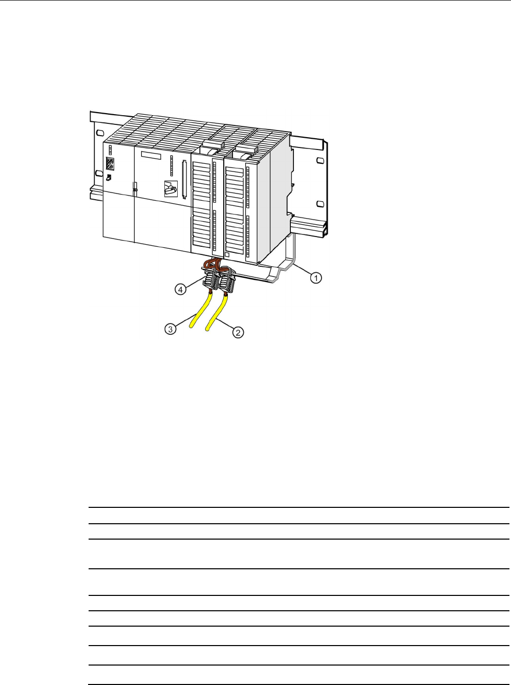
System integration
9.3 ASM 475
SIMATIC RF300
406 System Manual, 07/2017, C79000-G8976-C345-07
9.3.5
Shield connection
When the reader is connected to the ASM 475, the cable shield must be connected to a
shield terminal. Shield terminals and holding clips are standard components of the product
spectrum of S7-300.
①
Holding bracket
②
Cable to 2nd reader
③
Cable to 1st reader
④
Shield terminal
Figure 9-6 Shield terminal ASM 475
9.3.6
Technical data
Table 9- 7 Technical specifications for ASM 475
6GT2002-0GA10
Product type designation
ASM 475 communications module
Interfaces
Design of the interface
point-to-point link
RS-422
Number of connectable readers
2
Electrical connector design
• Backplane bus • S7-300 backplane bus
• PROFIBUS interface • (according to the head module)
• Industrial Ethernet interface • (according to the head module)

System integration
9.3 ASM 475
SIMATIC RF300
System Manual, 07/2017, C79000-G8976-C345-07 407
6GT2002-0GA10
• Supply voltage • Screw-type or spring-loaded terminals
Design of the interface
to the reader for communication
Screw-type or spring-loaded terminals
Mechanical specifications
Housing
• Material • Noryl
• Color • Anthracite
Supply voltage, current consumption, power loss
Supply voltage
24 VDC
Typical current consumption
• Without connected devices • 0.1 A
• Including connected devices • 1.0 A
Power dissipation of the module, typ.
2 Watts
Current consumption from I/O bus, max.
80 mA
Electrical isolation between S7-300 and RF300
Yes
Fuse 24 V for the reader
Yes, electronic
Permitted ambient conditions
Ambient temperature
• During operation (horizontal installation) 0 ... +60 ℃
• During operation (vertical installation) 0 ... +40 ℃
• During transportation and storage -40 ... +70 ℃
Degree of protection
IP20
Shock-resistant to IEC 61131-2
150 m/s
2
Vibration-resistant to IEC 61131-2
10 m/s
2
Design, dimensions and weight
Dimensions (L x W x H)
120 x 40 x 125 mm
Weight
0.2 kg
Type of mounting
S7-300 rack
Cable length for RS-422 interface, maximum 1000 m
Product properties, functions, components general
LED display design • 4 LEDs per reader connector
• 2 LEDs for device status
Product function transponder
file handler addressable
Yes
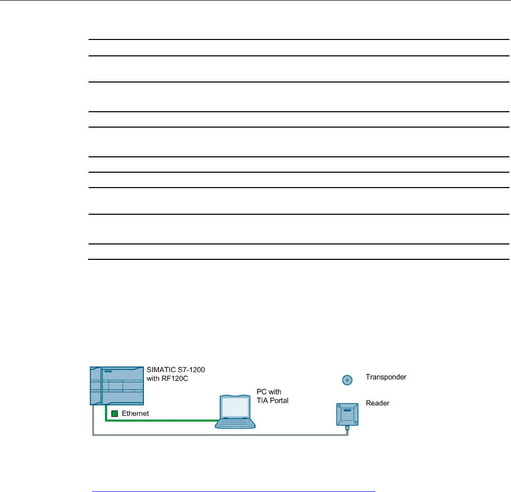
System integration
9.4 RF120C
SIMATIC RF300
408 System Manual, 07/2017, C79000-G8976-C345-07
6GT2002-0GA10
Protocol supported
S7 communication
Yes
Product functions management, configuration, engineering
Type of parameter assignment
Object manager, GSD
Type of programming FB 45, FB 55, FC 56
(FC 45/55 with restricted functionality)
Type of computer-based communication
2 words cyclic, 238 bytes acyclic
Transponder addressing
Direct access via addresses
Commands Initialize transponder, read data from transpond-
er, write data to transponder
Standards, specifications, approvals
Proof of suitability
CE, FCC, UL/CSA
9.4
RF120C
Configuration with RF120C
Figure 9-7 Configuration RF120C
For more detailed information, refer to the section " RF120C communications module
(https://support.industry.siemens.com/cs/ww/en/view/77485950)".
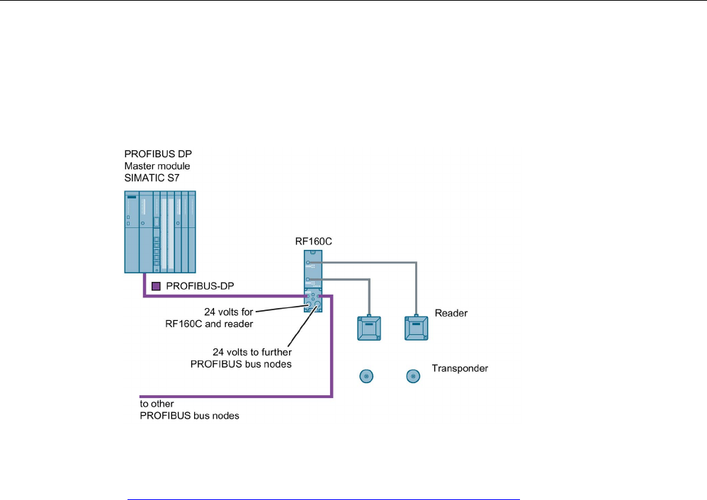
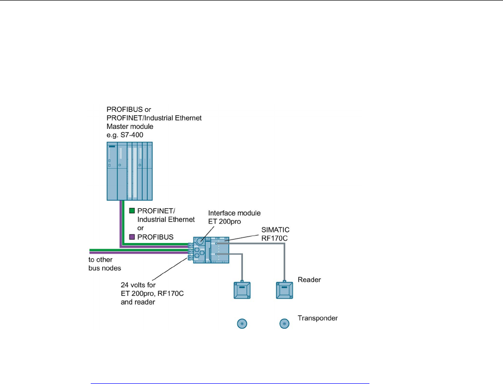
System integration
9.6 RF170C
SIMATIC RF300
410 System Manual, 07/2017, C79000-G8976-C345-07
9.6
RF170C
Configuration with RF170C
Figure 9-9 Configuration RF170C
For more detailed information, please refer to SIMATIC RF170C Operating Instructions
(https://support.industry.siemens.com/cs/ww/en/view/32622825).
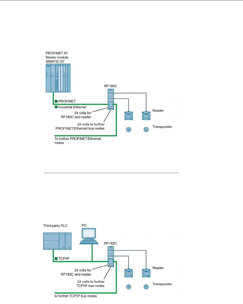
System integration
9.7 RF180C
SIMATIC RF300
System Manual, 07/2017, C79000-G8976-C345-07 411
9.7
RF180C
Configured with RF180C
Figure 9-10 Configuration of RF180C
For more detailed information, refer to SIMATIC RF180C Operating Instructions
(https://support.industry.siemens.com/cs/ww/en/view/30012157).
9.8
RF182C
Configuration with RF182C
Figure 9-11 Configuration with RF182C


SIMATIC RF300
System Manual, 07/2017, C79000-G8976-C345-07 413
System diagnostics
10
10.1
Error codes of the RF300 readers
Error codes of the RF300 readers
Note
Validity of the error codes
The following error codes apply only to RF300 readers with an RS
-422 interface (except for
Scanmode).
You have the following options to read out the error code:
● Directly on the reader/communication module by counting the flashing pattern of the red
error LED
● With the Ident profile at the output variable "Status"
Take into consideration the structure of the output variable in the table below
("0xE&FE$$00"; "&" = 1 ... 5; "$$" = error code).
● with FB 45 / FB 55 variable "error_MOBY"
Table 10- 1 Error codes of the readers
Flashing of the
red
LED operating
display on the
reader
Error code
(hexa-
decimal)
Description
00
00
No error
02 01 Presence error; possible causes:
• The active command was not carried out completely
• The transponder left the antenna field while the command was
being processed
• Communication problem between reader and transponder
05 05 Parameter assignment error, possible causes:
• Unknown command
• Incorrect parameter
• Function not allowed
06
06
Air interface faulty
11
0B
The MDS E transponder could not be successfully authenticated.

System diagnostics
10.1 Error codes of the RF300 readers
SIMATIC RF300
414 System Manual, 07/2017, C79000-G8976-C345-07
Flashing of the
red
LED operating
display on the
reader
Error code
(hexa-
decimal)
Description
12 0C The transponder memory cannot be written, possible causes:
• Hardware fault (memory faulty)
• Memory write-protected (corresponding OTP area has already
been written)
13 0D Error in the specified memory address (access attempted to non-
existent or non-accessible memory areas).
19 13 Buffer overflow: Insufficient buffer available in the reader for saving
the command
20
14
Major system fault (hardware fault)
21
15
Parameter assignment error: bad parameter in RESET command
24
18
Command was sent to a reader that has not yet been initialized
25
19
Previous command is still active
28 1C Antenna is not identified Possible causes:
• Antenna is not connected.
• Antenna cable is defective.
30
1E
Incorrect number of characters in frame
31
1F
Running command canceled by "RESET" command

System diagnostics
10.2 Diagnostics functions - STEP 7
SIMATIC RF300
System Manual, 07/2017, C79000-G8976-C345-07 415
10.2
Diagnostics functions - STEP 7
10.2.1
Overview
Extended diagnostic functions with SIMATIC RF300
With SIMATIC RF300, extended diagnostics functions are available with STEP 7 Classic /
Basic / Professional which simplify commissioning and maintenance.
Extensive diagnostics functions for the SIMATIC RF300 readers with the TIA Portal for STEP
7 Basic / Professional are being planned. With the aid of the Ident profile and the Ident
blocks, you can make different diagnostics queries.
You can access this diagnostics data using the SIMATIC function blocks and the commands
"Reader status" and "Tag status" (SLG-STATUS and MDS-STATUS). These two commands
can each be called with various attributes or modes (subcommands) for which corresponding
data structures (UDTs) are defined.
Table 10- 2 In RF300 mode
Command
Attributes
(mode)
Meaning
Reader-Status
(SLG-STATUS)
0x81 (01) Hardware and firmware configuration, parameterization sta-
tus
0x86 (06) Communication error counter, current command status
Tag-Status
(MDS-STATUS)
0x81 (01) Serial number of the transponder (UID), memory configura-
tion.
EEPROM write-protection status
0x82 (02) Serial number of the transponder (UID), HF field strength
value, communication error counter, presence counter (dura-
tion)
0x83 (03) Serial number of the transponder (UID), transponder type
identified in the antenna field (number = tag type, see Reset
- "ftim" parameter), memory configuration, write protection
status (OTP), size and number of blocks in the user memory
Overview of the diagnostic functions
Table 10- 3 In ISO mode: ISO 15693, ISO 18000-03 or ISO 14443
Command
Attributes
Meaning
Reader-Status
(SLG-STATUS)
0x81 (01) Hardware and firmware configuration, parameterization sta-
tus
0x86 (06)
Communication error counter, current command status
Tag-Status
(MDS-STATUS)
0x83 (03) Serial number of the transponder (UID), transponder type
identified in the antenna field (number = tag type, see Reset
- "ftim" parameter), memory configuration, write protection
status (OTP), size and number of blocks in the user memory

System diagnostics
10.2 Diagnostics functions - STEP 7
SIMATIC RF300
416 System Manual, 07/2017, C79000-G8976-C345-07
10.2.2
Reader diagnostics with "reader status" (SLG-STATUS)
With this command you can query the status and diagnostics data of the reader.
Note
Scope of the described UDTs
Note that below only the variables are listed that are relevant for the RF300 system. You will
find the full UDTs in the manual "Ident Profile and Ident Blocks".
Attributes "0x81" (mode 01), corresponds to UDT 110
Table 10- 4 Input parameter
Name
Type
Possible Values
(hexadecimal)
Comment
hardware char
00
01
02
03
04
05
0A
0B
0C
0D
Type of hardware
= RF310R, RF340R, RF350R
= RF380R
= RF310R (ISO)
= RF380R (ISO)
= RF340R (ISO), RF350R (ISO)
= RF310R (ISO)
= RF310R, 2nd generation
= RF340R, 2nd generation
= RF350R, 2nd generation
= RF380R, 2nd generation
hardware_version word
00 ... FF
HW version
= Version (high byte): unused (00)
00 ... FF
HW version
= Version (low byte)
47 = Readers of the 1st generation
07 = Readers of the 1st generation
11 = Readers of the 1st generation
10 = Readers of the 2nd generation
29 = Readers of the 2nd generation
2B = Readers of the 2nd generation
2C = Readers of the 2nd generation
loader_version word
00 ... FF
00 ... FF
Version of loader
= Version (high byte)
= Version (low byte)

System diagnostics
10.2 Diagnostics functions - STEP 7
SIMATIC RF300
System Manual, 07/2017, C79000-G8976-C345-07 417
Name
Type
Possible Values
(hexadecimal)
Comment
firmware char 00 ... FF Type of firmware
01, 02, 03 = Readers of the 1st generation
F = Full version for readers of the 2nd generation
P = Pilot version for readers of the 2nd generation
firmware_version word
00 ... FF
00 ... FF
Firmware version
= Version (high byte)
= Version (low byte)
driver char
31
32
33
Driver version 3964R
= 3964R
= ASCII
= ASCII/ScanMode
driver_version word
00 ... FF
00 ... FF
Version of driver
= Version (high byte)
= Version (low byte)
interface byte
01
02
Interface type
= RS422
= RS232 (only RF380R)
baud byte
01
03
05
Transmission speed
= 19.2 Kbaud
= 57.6 kBaud
= 115,2 Kbaud
distance_limiting_SLG byte -- Readers of the 1st generation: With this parameter you can
change the transmit power (output power) of the RF380R
reader of the 1st generation (6GT2801-3AB10). When doing
this, remember that the change to the transmit power will affect
the detection in the limit range (upper/ lower operating dis-
tance), as well as the minimum distance that is to be main-
tained between adjacent RF380Rs.
Settings outside the specified range have the effect that the
default value (1.25 W) will be set. In this case for reasons of
compatibility there is no error message.
Readers of the 2nd generation: This setting is not necessary
with the RF380R readers of the 2nd generation (6GT2801-
3BAx0) because the power limits are optimized automatically
depending on the reader-transponder distance. For reasons of
compatibility this setting can nevertheless be made. Note that
the values "02", "03" and "04" bring about a reduction of the
power of approximately 50%.
Transmit power
02
0.5 W
03
0.75 W
04
1.0
05 1.25 W (default)
06
1.5 W
07 1.75 W

System diagnostics
10.2 Diagnostics functions - STEP 7
SIMATIC RF300
418 System Manual, 07/2017, C79000-G8976-C345-07
Name
Type
Possible Values
(hexadecimal)
Comment
08
2.0 W
multitag_SLG byte
01
Number of transponders that can be processed in the antenna
field
= Single tag mode
field_ON_time_SLG byte
00
01
03
04
05
06
07
08
0E
10
20
31
FF
Selection of the transponder types used
= RF300 (RF3xxT)
= ISO 15693 general
= ISO 15693 (Infineon, MDS D3xx)
= ISO 15693 (Fujitsu - 2 kB, MDS D4xx)
= ISO 15693 (NXP, MDS D1xx)
= ISO 15693 (TI, MDS D2xx)
= ISO 15693 (STM, MDS D261)
= ISO 15693 (Fujitsu - 8 kB, MDS D5xx)
= ISO (setting with "scanning_time" and "fcon")
= RF300 (RF3xxT)
= ISO 14443 (MOBY E, E6xx)
= General Mode
= Setting with "scanning_time" and "fcon"
status_ant byte
01
02
Status of the antenna
= Antenna is on
= antenna is off
MDS_control byte
00
01
04
Presence check
= Operation without presence check
= Operation with presence check (antenna is permanently
switched on.)
= Operation without presence check (antenna is switched off.)
The antenna is only switched on when one of the following
commands is sent.
Read, Write, Init, Tag-Status
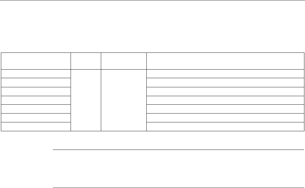
System diagnostics
10.2 Diagnostics functions - STEP 7
SIMATIC RF300
System Manual, 07/2017, C79000-G8976-C345-07 419
Attributes "0x86" (mode 06), corresponds to UDT 280
Table 10- 5 Error counter
Name
Type
Possible Values
(hexadecimal)
Comment
FZP
byte 00 ... FF
= Error counter, passive (errors during idle time)
ABZ = Abort counter
CFZ
= Code error counter
SFZ
= Signature error counter
CRCFZ
= CRC error counter
BSTAT
= Current command status
ASMFZ
= Interface problems to host (CM/PC) parity, BCC, frame error
Note
Counter values are deleted.
Note that the counter values are deleted after they have been read out (command "Reader
status" or "SLG
-STATUS").
Explanations:
● "FZP": counts interference pulses when communication with a transponder is not taking
place (e.g. electromagnetic interference caused by contactors, motors, etc.). Counter
values can, however, also be generated when a transponder is located at the edge of the
field even when there is no external interference.
● "ABZ", "CFZ", "SFZ" and "CRCFZ" are counters for protocol errors which may occur
during reader-transponder communication. This can be caused by unsuitable
reader/transponder positioning (e.g. transponder on field boundary, several transponders
in the antenna field) or external EMC interference.
To ensure clear diagnostics of the quality of communication, it is recommended that a
"Reader status" (SLG STATUS) command with attribute "0x86" (mode 06) is executed
following receipt of the presence message to reset the error counters.
The protocol error counters are not mutually independent. If a code error (CFZ) occurs, this
will cause a signature (SFZ) or CRC- (CRCFZ) error.
● "BSTAT" is the status for the most recently executed command. A value other than 0
means that the previous command was repeated by the reader due to faults (see above).
● "ASMFZ" signals line-conducted communication interference between the
communications module and the reader. Faults of this type can be caused by contact
problems on the connector or the cable connection.
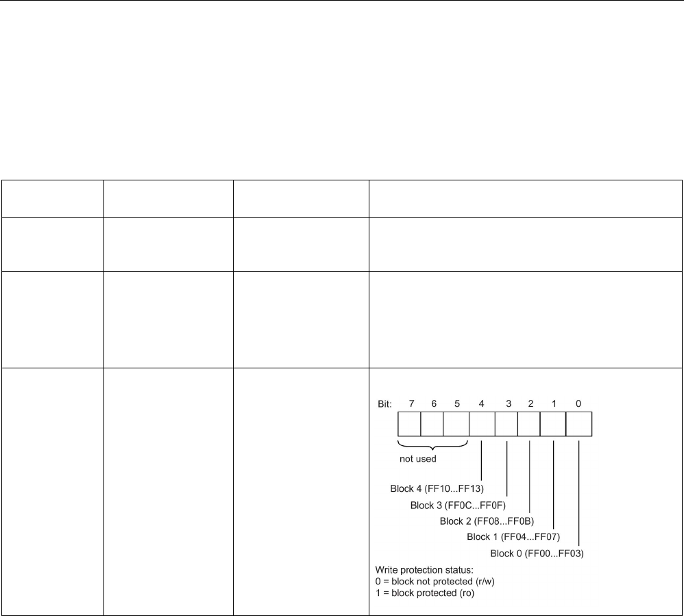
System diagnostics
10.2 Diagnostics functions - STEP 7
SIMATIC RF300
420 System Manual, 07/2017, C79000-G8976-C345-07
10.2.3
Transponder diagnostics with "Tag status" (MDS-STATUS)
With this command you can query the status and diagnostics data from the transponder
currently located in the antenna field.
Attribute "0x04" (mode 01), corresponds to UDT 260 (only for RF300 transponders)
Name
Type
Possible Values (hex-
adecimal)
Comment
UID array[1…8] byte
000000005555555 ...
00000000FFFFFFFF
Unique identifier
= b0-31: 4 byte TAG ID, b32-63: 0
MDS_type byte
01
02
03
04
Transponder memory configuration
= Transponder without FRAM
= Transponder with FRAM 8 KB
= Transponder with FRAM 32 KB
= Transponder with FRAM 64 KB
Lock_state byte 0 ... FF EEPROM write protection status

System diagnostics
10.2 Diagnostics functions - STEP 7
SIMATIC RF300
System Manual, 07/2017, C79000-G8976-C345-07 421
Attribute "0x82" (mode 02), corresponds to UDT 270 (only for RF300 transponders)
Name
Type
Possible Values (hex-
adecimal)
Comment
UID array[1…8] byte
0000000055555555 ...
00000000FFFFFFFF
Unique identifier
= b0-31: 4 byte TAG ID, b32-63: 0
LFD byte 0 ... FF = Value for field strength determined in the transponder
FZP
byte
0 ... FF
= Error counter (passive) ➙ errors during idle time
FZA
byte
0 ... FF
= Error counter (active)
ANWZ
byte
0 ... FF
= Presence counter
Note
Counter values are deleted.
All counter values are deleted when the transponder exits the antenna field or when the
antenna is switched of
f.
Explanations:
● "LFD" is a measured value for the field strength that is determined in the transponder.
The lower the value, the higher the field strength.
● "FZP" counts interference pulses when communication with a transponder is not taking
place (e.g. electromagnetic interference caused by contactors, motors, etc.). Counter
values can also be generated when a transponder is located at the edge of the field even
when there is no external interference.
● "FZA" counts errors that can occur during reader-to-transponder communication. This can
be caused by unsuitable reader/transponder positioning (e.g. transponder on field
boundary, several data carriers in the field) or external electromagnetic interference.
● "ANWZ" is the value for the time that the transponder remains in the field before the "Tag-
Status" (MDS STATUS) with attribute "0x82" (mode 02) is executed. A time step is 10
ms. The maximum time that can be recorded is therefore 2.5 s.

System diagnostics
10.2 Diagnostics functions - STEP 7
SIMATIC RF300
422 System Manual, 07/2017, C79000-G8976-C345-07
Attribute "0x83" (mode 03), corresponds to UDT 230
Name
Type
Possible Values (hex-
adecimal)
Comment
UID array[1…8] byte
0000000000000000 ...
FFFFFFFFFFFFFFFF
Unique identifier
=8 byte UID, MSB first
MDS_type byte
00
03
04
05
06
07
08
11
12
13
14
21
22
23
Transponder type (vendor, identification)
= ISO 15693 general
= ISO 15693 (Infineon, MDS D3xx)
= ISO 15693 (Fujitsu - 2 kB, MDS D4xx)
= ISO 15693 (NXP, MDS D1xx)
= ISO 15693 (TI, MDS D200)
= ISO 15693 (STM, MDS D261)
= ISO 15693 (Fujitsu - 8 kB, MDS D5xx)
= RF300 transponder (0 kB)
= RF300 transponder (8 kB)
= RF300 transponder (32 kB)
= RF300 transponder (64 kB)
= ISO 14443 (NXP, 1 kB, MDS E)
= ISO 14443 (Infineon, 1 kB, MDS E)
= ISO 14443 (NXP, 4 kB, MDS E)
IC_version
byte
0 ... FF
Chip version
size byte 0 ... FF Memory size in bytes
depending on transponder type, e.g. MDS D3xx: 992
bytes
lock_state byte 0 ... FF Lock state, OTP information:
One bit is used per block (4 x 4 bytes or 2 x 8 bytes)
(bit = 1: block is locked)
Example:
01 = Block 1 of address FF80 ... FF83 is locked or
03 = Block 1 and 2 of address FF80 ... FF87 are
locked,
e.g. for the Philips SL2 ICS20 (MDS D124, D160 or
D100).
This chip provides a usable memory with 112 bytes
EEPROM from address 0000 - 006F (total OTP area
"0060 ... 006F"). In this memory, the locked area corre-
sponds to the addresses 0060 ... 0063 or 0060 ... 0067
block_size byte 0 ... FF Block size of the transponder
depending on transponder type, e.g. MDS D3xx: 4
bytes
nr_of_blocks byte 0 ... FF Number of blocks
depending on transponder type, e.g. MDS D3xx: 248
bytes
SIMATIC RF300
System Manual, 07/2017, C79000-G8976-C345-07 423
Appendix
A
A.1
Certificates and approvals
All the latest RFID radio approvals are available on the Internet
(http://www.siemens.com/rfid-approvals).
Labeling
Description
Conformity acc. to the RED EU directive
Notes on CE marking
The following applies to the system described in this documentation:
The CE marking on a device indicates the corresponding approval.
DIN ISO 9001 certificate
The quality assurance system for the entire product process (development, production, and
marketing) at Siemens fulfills the requirements of ISO 9001 (corresponds to EN29001:
1987).
This has been certified by DQS (the German society for the certification of quality
management systems).
EQ-Net certificate no.: 1323-01
Country-specific approvals
Safety
If the device has one of the following markings the corresponding approval has been
obtained:
Labeling
Description
Underwriters Laboratories (UL) to UL 60950 Standard (I.T.E), UL508
or UL61010-1/UL61010-2-201 (IND.CONT.EQ)
Underwriters Laboratories (UL) according to Canadian standard C22.2
No. 60950 (I.T.E), C22.2 No. 142 or C22.2 NO. 61010-1-12
(IND.CONT.EQ)
Underwriters Laboratories (UL) according to Standard UL 60950,
Report E11 5352 and Canadian standard C22.2 No. 60950 (I.T.E),
UL508 or UL61010-1/UL61010-2-201 (IND.CONT.EQ) and C22.2 No.
142 or C22.2 NO. 61010-1-12 (IND.CONT.EQ)
Appendix
A.1 Certificates and approvals
SIMATIC RF300
424 System Manual, 07/2017, C79000-G8976-C345-07
Labeling
Description
UL recognition mark
Canadian Standard Association (CSA) acc. to standard C22.2. No.
60950 (LR 81690), C22.2 No. 142 or C22.2 NO. 61010-1-12 (LR
63533)
Canadian Standard Association (CSA) acc. to American Standard UL
60950 (LR 81690), UL508 or UL61010-1/UL61010-2-201 (LR 63533)
This product meets the requirements of the AS/NZS 3548 Norm.
USA (FCC)
This device complies with Part 15 of the FCC Rules.
FCC ID: NXW-RF...
Canada (IC) Canada (IC)
This device complies with Industry Canada licence-exempt RSS
standard(s).
IC: 267X-RF...
Russia, Belarus and Kazakhstan
Brazil (ANATEL)
ANATEL-ID: XXXX-YY-ZZZZ
Mexico (COFETEL)
Mexico (COFETEL)
South Africa (ICASA)
China (CMIIT) China (CMIIT)
CMIIT ID: XXXXYYZZZZ
South Korea (KCC)
Japan (VCCI)
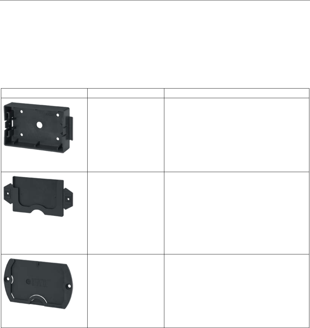
Appendix
A.2 Accessories
SIMATIC RF300
System Manual, 07/2017, C79000-G8976-C345-07 425
A.2
Accessories
A.2.1
Transponder holders
Table A- 1 Overview of the transponder holders and spacers
Product photo
Insertable transponders
Characteristics
6GT2190-0AA00
• MDS D100
• MDS D200
• MDS D400
• MDS E600
• MDS E611
• RF360T
• Spacer for mounting on metal, in conjunction with the
fixing pocket 6GT2190-0AB00
• Distance from transponder to metal: 25 mm
• Mounting: 4 x M4 screws
• Material: PA6
• Weight: 31 g
• Dimensions (L x W x H): 110 x 62 x 24 mm
6GT2190-0AB00
• MDS D100
• MDS D200
• MDS D400
• MDS E600
• MDS E611
• RF360T
• Fixing pocket in conjunction with spacer 6GT2190-
0AA00
• Mounting:
– Locks into spacer
– 2 x screws/nails
– Tacked
• Material: PA6
• Weight: 12 g
• Dimensions (L x W x H): 121 x 57 x 5 mm
6GT2390-0AA00
• MDS D100
• MDS D200
• MDS D400
• Fixing pocket not suitable for mounting directly on
metal
• Mounting: 2 x M4 countersunk screws
• Material: PA6
• Weight: 21 g
• Dimensions (L x W x H): 110 x 65 x 5 mm
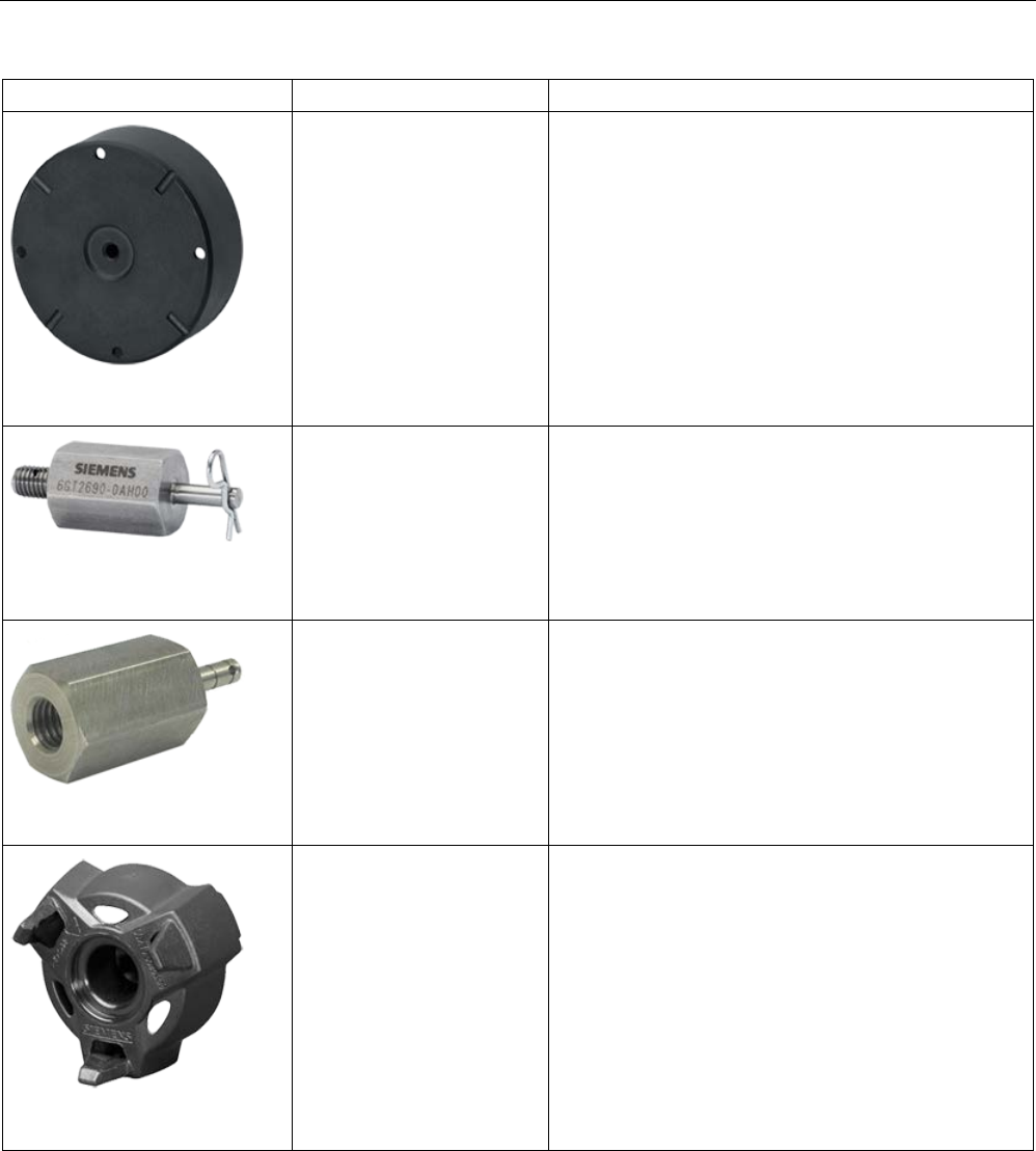
Appendix
A.2 Accessories
SIMATIC RF300
426 System Manual, 07/2017, C79000-G8976-C345-07
Product photo
Insertable transponders
Characteristics
6GT2690-0AA00
• MDS D139
• MDS D339
• Spacer for mounting on metal
• Distance from transponder to metal: 30 mm
• Mounting: 1 x M5 stainless steel screw
• Tightening torque: 1.5 Nm
• Material: PPS
• Weight: 50 g
• Dimensions (Ø x H): 85 x 30 mm
6GT2690-0AH00
• MDS D139
• MDS D339
• Quick change holder for mounting on metal
• Distance from transponder to metal: 30 mm
• Mounting: Screw-in
• Material: Stainless steel VA
• Weight: 80 g
• Dimensions (Ø x H): 22 x 60 mm
6GT2690-0AH10
• MDS D139
• MDS D339
• Quick change holder for mounting on metal
• Distance from transponder to metal: 30 mm
• Mounting: Screw-in
• Material: Stainless steel VA
• Weight: 60 g
• Dimensions (Ø x H): 22 x 47 mm
6GT2690-0AK00
• MDS D124
• MDS D324
• MDS D424
• MDS D524
• Spacer for mounting on metal
• Distance from transponder to metal: 15 mm
• Mounting: 1 x M4 countersunk screw
• Tightening torque: ≤ 1 Nm
• Material: PPS
• Weight: Approx. 4 g
• Remounting cycles: min. 10
• Dimensions (Ø x H): 36 x 22 mm
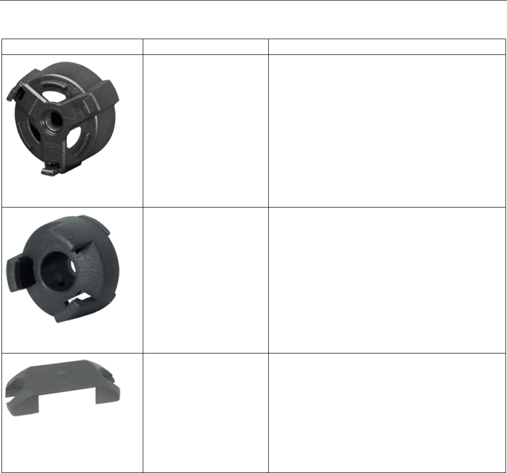
Appendix
A.2 Accessories
SIMATIC RF300
System Manual, 07/2017, C79000-G8976-C345-07 427
Product photo
Insertable transponders
Characteristics
6GT2690-0AL00
• MDS D126
• MDS D426
• MDS D526
• MDS E624
• Spacer for mounting on metal
• Distance from transponder to metal: 25 mm
• Mounting: 1 x M4 countersunk screw
• Tightening torque: ≤ 1 Nm
• Material: PA6
• Weight: Approx. 12 g
• Remounting cycles: min. 10
• Dimensions (Ø x H): 59 x 30 mm
6GT2690-0AG00
• MDS D160
• MDS D460
• Spacer for mounting on metal
• Distance from transponder to metal: 10 mm
• Mounting: 1 x M3 countersunk screw
• Material: PA6
• Weight: 2 g
• Dimensions (Ø x H): 20 x 14 mm
6GT2690-0AE00
• MDS D423
• RF330T
• Fixing hood
• Mounting: 2 x M4 or 2 x M5 screws with max. head
diameter of 9.5 mm
• Tightening torque ≤ 0.8 Nm (M4 only with flat wash-
er)
• Material: PPS
• Weight: 3 g
• Dimensions (L x W x H): 49.4 x 20 x 9.8 mm
Dimensional drawings
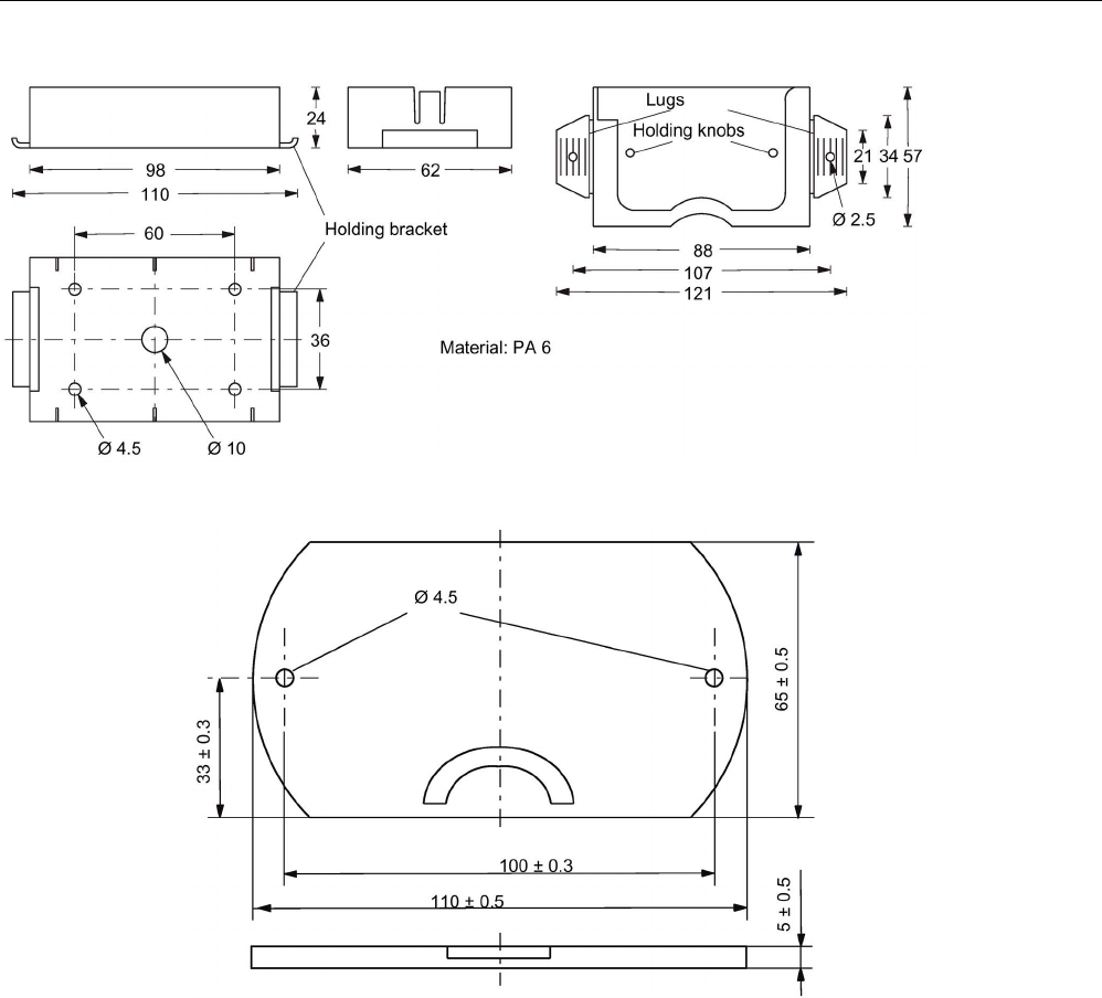
Appendix
A.2 Accessories
SIMATIC RF300
428 System Manual, 07/2017, C79000-G8976-C345-07
Figure A-1 Dimension drawing of spacer 6GT2190-0AA00 with fixing pocket 6GT2190-0AB00
Figure A-2 Dimension drawing of fixing pocket 6GT2390-0AA00
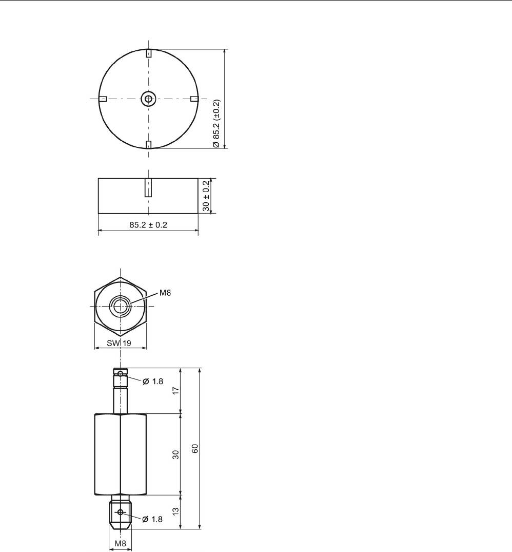
Appendix
A.2 Accessories
SIMATIC RF300
System Manual, 07/2017, C79000-G8976-C345-07 429
Figure A-3 Dimension drawing of spacer 6GT2690-0AA00
Figure A-4 Dimension drawing of quick change holder 6GT2690-0AH00
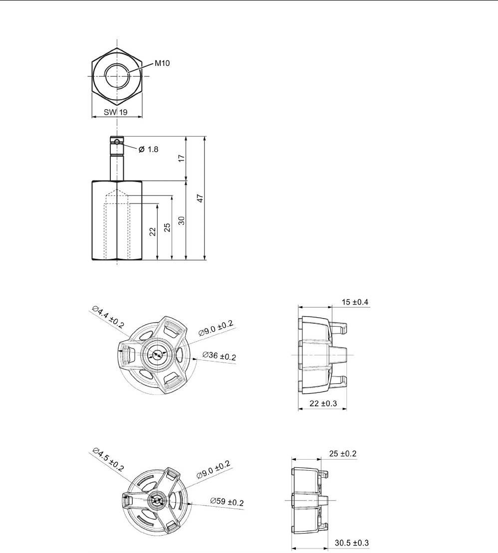
Appendix
A.2 Accessories
SIMATIC RF300
430 System Manual, 07/2017, C79000-G8976-C345-07
Figure A-5 Dimension drawing of quick change holder 6GT2690-0AH10
Figure A-6 Dimension drawing of spacer 6GT2690-0AK00
Figure A-7 Dimension drawing of spacer 6GT2690-0AL00
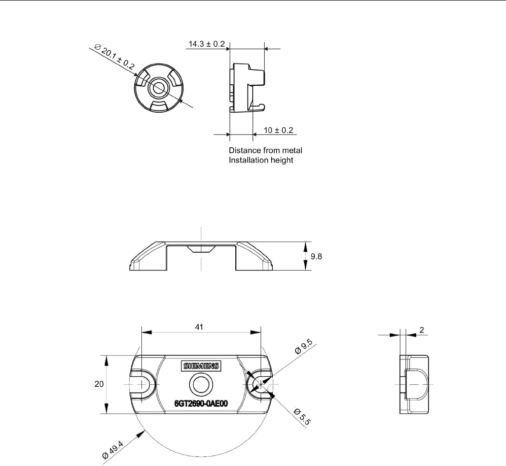
Appendix
A.2 Accessories
SIMATIC RF300
System Manual, 07/2017, C79000-G8976-C345-07 431
Figure A-8 Dimension drawing of spacer 6GT2690-0AG00
Figure A-9 Dimension drawing of fixing hood 6GT2690-0AE00

Appendix
A.2 Accessories
SIMATIC RF300
432 System Manual, 07/2017, C79000-G8976-C345-07
A.2.2
MOBY I migration
The RF300 readers of the new generation provide the option of simple migration of existing
MOBY I systems to SIMATIC RF300. The so-called MOBY I emulation processes frames of
the MOBY I protocol on its serial interface and communicates with the established RF300
transponders.
If the RF300 reader is connected to a communications module with MOBY I capability, the
reader automatically recognizes the serial protocol and sets the MOBY I protocol. As a
communications module with MOBY I capability, all the communications modules sold for
MOBY I count regardless of the mode in which the MOBY I communications modules are
operated. This property allows even projects with the ECC mode turned on or with file
handlers to be migrated.
Communication modules with MOBY I capability:
RF180C, RFID 181EIP, RF170C, ASM 456, ASM 475, ASM 470, ASM450, ASM 451, ASM
452, ASM 472, ASM 473, ASM 424, ASM 454, ASM 400, CM 422, CM 423, ASM 410, ASM
420, ASM 421, ASM 440, ES030
With the aid of the adapter cable (0.3 m; article number 6GT2091-4VE30) you can migrate
existing MOBY I projects without needing to re-cable the connected RFID devices.
The transfer is as usual with MOBY I with a transmission speed of 19.2 kBd. The
transmission speed in the application is identical (or slightly slower) than with the original
MOBY I hardware.
NOTICE
Changed field geometry
When replacing MOBY I components with RF300 components note that the field geometry
changes.
Note
LED reaction of the readers in MOBY I mode
Presence and errors are not displayed on the r
eader. These are only displayed via the
connected CM.
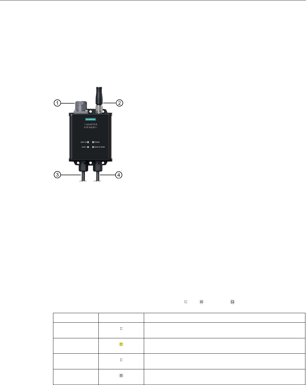
Appendix
A.2 Accessories
SIMATIC RF300
System Manual, 07/2017, C79000-G8976-C345-07 433
Design of the Y adapter
With the aid of the Y adapter (article number 6GT2090-4VE00) a slow migration of a MOBY I
application to RF300 is possible. The Y adapter is mounted in the vicinity of a MOBY I SLG.
It forwards signals of a communications module both to the MOBY I SLG and to the RF300
reader to be newly installed. The transponder commands are handled either with a MOBY I
transponder or with an RF300 transponder. To do this, no change to the MOBY I application
is necessary.
①
ASM TxD
(X1)
Connector for the communications module;
SLG plug, 6-pin acc. to EN 175201-804
②
Power
(X4)
Optional 24 VDC supply voltage;
M12 plug, 4-pin
③
MOBY l
(X2)
Connector for the MOBY I-SLG;
SLG socket (angled), 6-pin acc. to EN 175201-804; cable length: 0.5 m
④
SIMATIC
RF300
(X3)
Connector for RF 300 reader;
M12 socket, 8-pin, cable length: 0.5 m max. 2 m cable extension permitted
Figure A-10 Connection graphic of the MOBY Y adapter for MOBY I
The operational statuses of the Y-adapter are displayed by four LEDs. The LEDs can adopt
the colors yellow and green and the statuses off , on , flashing :
Labeling
LED
Description
ASM TxD
(X1)
No communication module connected to the Y-adapter.
ASM TxD
(X1)
A communication module is connected to the Y-adapter.
Power
(X4)
The Y-adapter is switched off.
Power
(X4)
The Y-adapter is switched on. All connected components are
supplied with power.
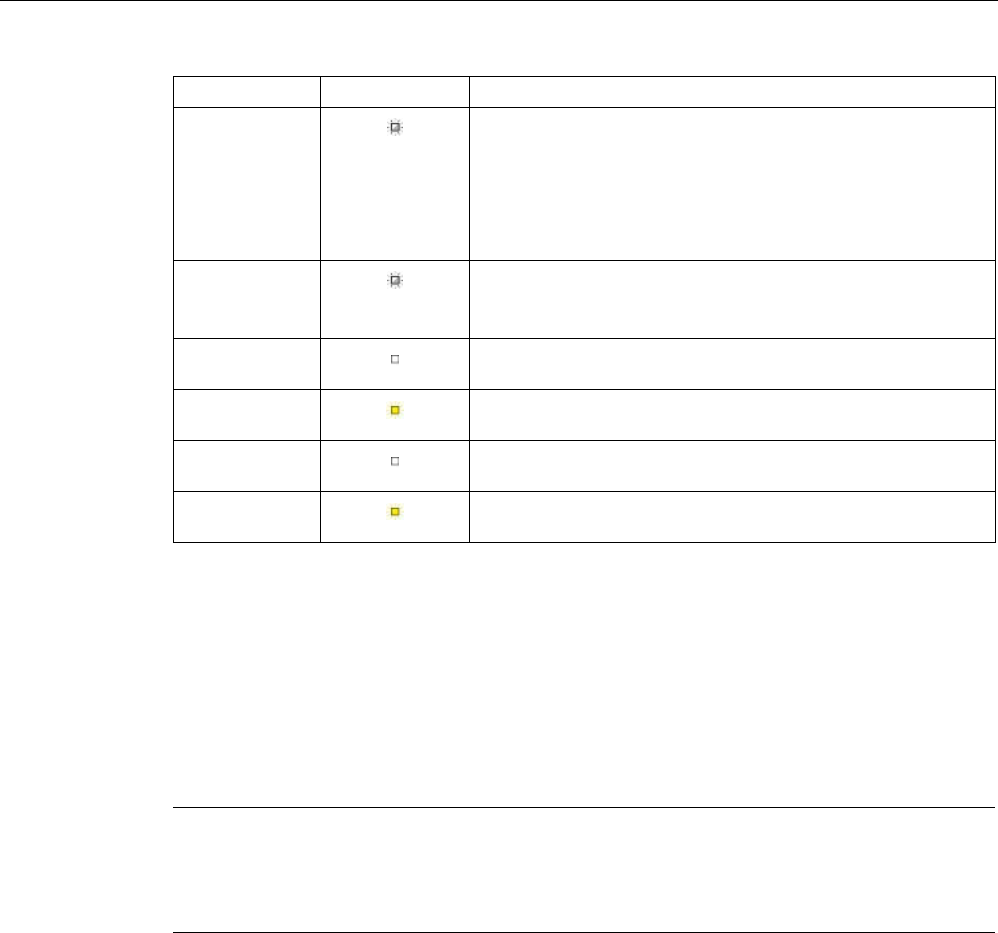
Appendix
A.2 Accessories
SIMATIC RF300
434 System Manual, 07/2017, C79000-G8976-C345-07
Labeling
LED
Description
Power
(X4) Flashes at 1:1 rate
The following options are available:
• Supply voltage at X4, but not at X1.
• Supply voltage at X1, but not at X4.
• No component is connected to either X2 or X3.
Power
(X4) Flashes at 1:10 rate; indicates an error.
A transponder is installed on the MOBY I-SLG as well as on the
RF300 reader. The user program displays the error "03".
MOBY I
(X2)
No MOBY I-SLG connected to the Y-adapter or the MOBY I-
SLG does not work.
MOBY I
(X2)
A ready MOBY I-SLG is connected to the Y-adapter. If the LED
gets brighter, there is communication to a MOBY I transponder.
SIMATIC RF300
(X3)
No RF300 reader connected to the Y-adapter or the RF300
reader does not work.
SIMATIC RF300
(X3)
A ready RF300 reader is connected to the Y-adapter. If the LED
gets brighter, there is communication to a RF300 transponder.
Optional supply voltage
Use the optional supply voltage under the following conditions:
● If the communication module (X1) cannot supply the current required for 2 readers and
the Y-adapter.
● If long cables between the communication module (X1) and the MOBY I-SLG (X2) cause
the voltage at the Y-adapter to drop below the minimum supply voltage of 20 V.
Note
Questions on migration
If you have questions about migration, please contact the Siemens Industry Onli
ne Support
(section "
Service & Support (Page 451)").
Command set
The complete command set of the MOBY I SLGs is supported by the RF300 readers. You
will find a list of the commands and a description of the commands in the manuals "FB 45"
and "FC 56". These manuals can be found in the archive of the DVD "Ident Systems
Software & Documentation" (6GT2080-2AA20).

Appendix
A.2 Accessories
SIMATIC RF300
System Manual, 07/2017, C79000-G8976-C345-07 435
A.2.3
DVD "Ident Systems Software & Documentation"
The DVD contains:
● FB/FC for SIMATIC, 3964R
● Drivers for DOS / Windows
● C libraries
● PC demonstration program
● RFID documentation in PDF format, especially RFID system manuals, programming
instructions and operating instructions
Table A- 2 Ordering data DVD
Article number
DVD "Ident Systems Software & Documentation"
6GT2080-2AA20
Note
Notes on "Ident Systems Software" and licensing
When purchasing a communication module or an interface module, no software or
documentation is supplied. The "Ident Systems Software & Documentation" DVD contains all
available FBs/FCs for the SIMATIC, C libraries, demo programs, etc. and needs to be
ordered separately. In addition, the DVD contains the complete Ident documentation
(Ge
rman and English) in PDF format.
The purchase of a communications module or an interface module includes a payment for
the use of the software, including documentation, on the "Ident Systems Software &
Documentation" DVD and the purchaser acquires the righ
t to make copies (copy license)
insofar as they are required as part of the customer
-specific application or development for
the plant.
The contract accompanying the DVD pertaining to the use of software products against a
one
-off payment also applies.
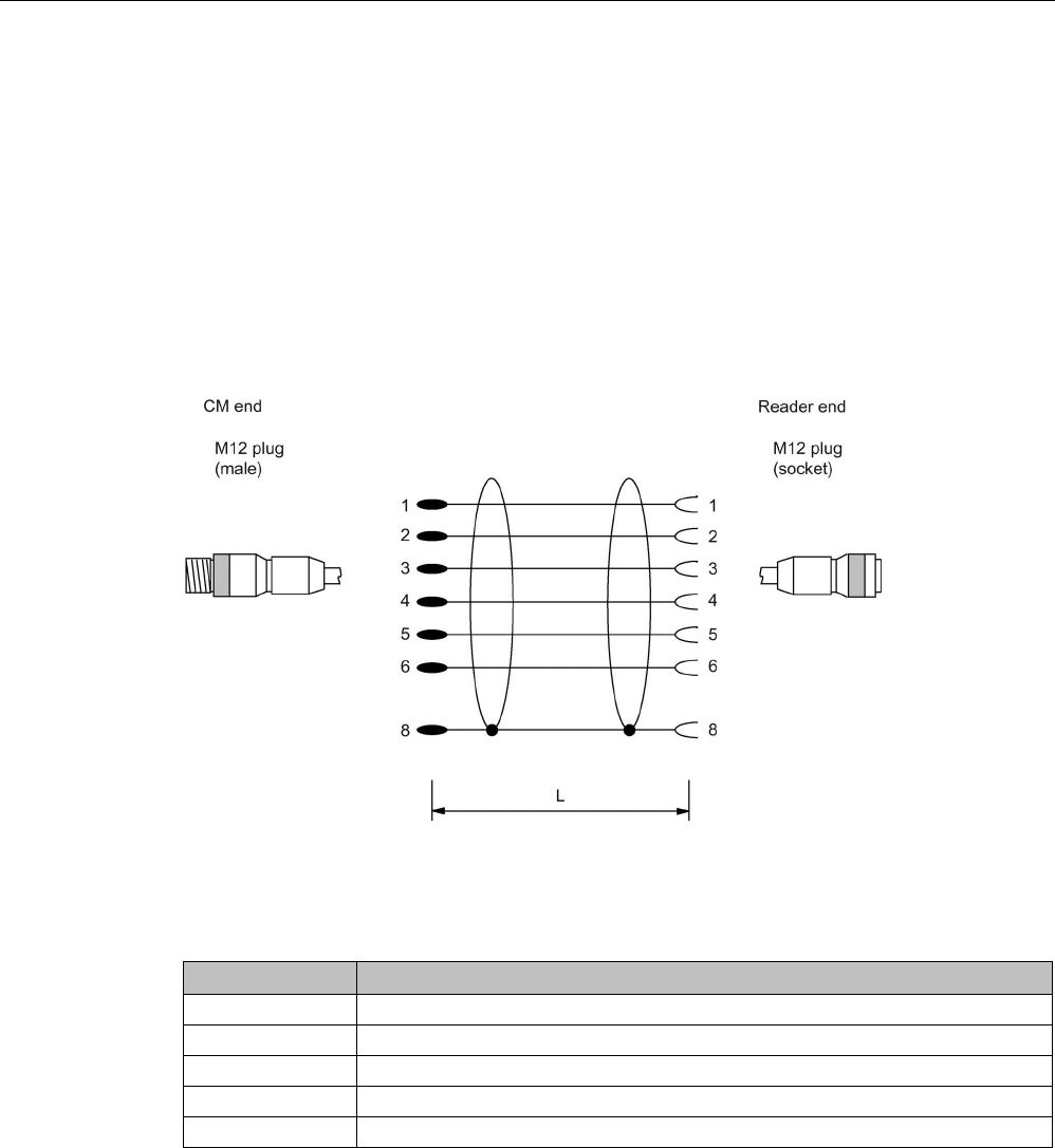
Appendix
A.3 Connecting cable
SIMATIC RF300
436 System Manual, 07/2017, C79000-G8976-C345-07
A.3
Connecting cable
In the following chapter, you will find an overview of the connecting cables between the
readers and communication modules or PCs.
A.3.1
RF3xxR reader (RS-422) with ASM 456 / RF160C / RF170C / RF180C /
RF182C
Connecting cable with straight connector
Figure A-11 Connecting cable between ASM 456, RF160C, RF170C, RF180C, RF182C and RF3xxR
reader (RS-422)
Table A- 3 Ordering data
Length L
Article number
2 m 6GT2891-4FH20
5 m
6GT2891-4FH50
10 m
6GT2891-4FN10
20 m
6GT2891-4FN20
50 m
6GT2891-4FN50
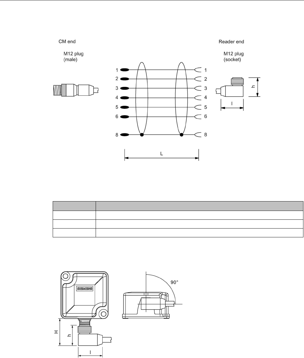
Appendix
A.3 Connecting cable
SIMATIC RF300
System Manual, 07/2017, C79000-G8976-C345-07 437
Connecting cable with angled connector
Figure A-12 Connecting cable between ASM 456, RF160C, RF170C, RF180C and RF3xxR reader
(RS-422) with angled connector
Table A- 4 Ordering data
Length L
Article number
2 m
6GT2891-4JH20
5 m
6GT2891-4JH50
10 m 6GT2891-4JN10
The angled connector has a height of h = 29 mm and a length of l = 38 mm. Remember that
due to the construction, the distance between the edge of the connector and the edge of the
reader housing (H) is higher.
Figure A-13 Distance between connector edge and housing edge
The distance between the connector edge and the housing edge of the reader (H) depends
on the reader being used and can be up to 38 mm. If you look at the front of the reader, the
angled connector always points to the right and runs parallel to the housing.
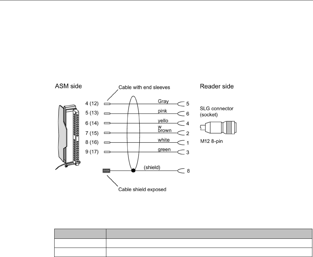
Appendix
A.3 Connecting cable
SIMATIC RF300
438 System Manual, 07/2017, C79000-G8976-C345-07
A.3.2
Reader RF3xxR (RS422) with ASM 475
Reader connection system
The connecting cable has a length of 2 m (standard) and 5 m. Extensions up to 1000 m are
possible with the 6GT2891-4E… plug-in cables.
Figure A-14 Structure of the connecting cable between ASM 475 and RF3xx reader with RS-422
Table A- 5 Ordering data
Length L
Article number
2 m
6GT2891-4EH20
5 m 6GT2891-4EH50
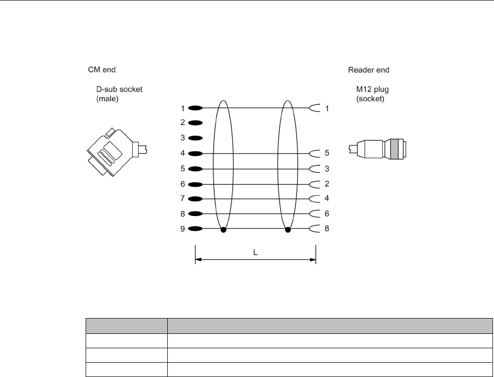
Appendix
A.3 Connecting cable
SIMATIC RF300
System Manual, 07/2017, C79000-G8976-C345-07 439
A.3.3
Reader RF3xxR (RS-422) with RF120C
Figure A-15 Connecting cable between RF120C and RF3xxR reader (RS-422)
Table A- 6 Ordering data
Length L
Article number
2 m
6GT2091-4LH20
5 m
6GT2091-4LH50
10 m
6GT2091-4LN10
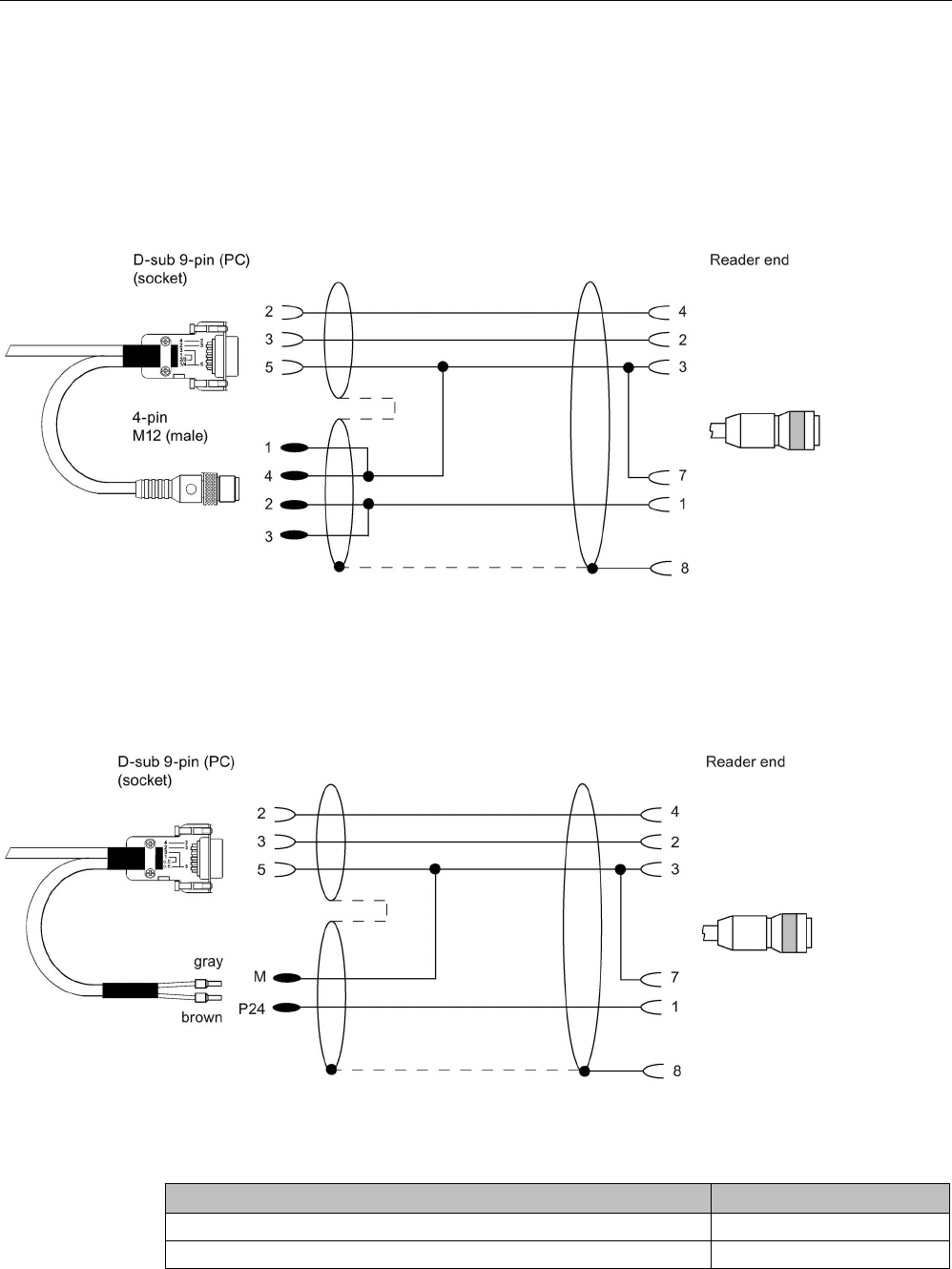
Appendix
A.3 Connecting cable
SIMATIC RF300
440 System Manual, 07/2017, C79000-G8976-C345-07
A.3.4
Reader RF380R (RS232) - PC
The connecting cables have a length of 5 m. The outgoing cable for the power supply has a
length of 0.5 m.
With 4-pin power supply connector
Figure A-16 Connecting cable between PC and RF380R (RS-232) with 4-pin power supply connector
Suitable power supply unit: e.g. wide-range power supply unit
With open ends for the power supply
Figure A-17 Connecting cable between PC and RF380R (RS-232) with open ends for the power supply
Table A- 7 Ordering data connecting cable
Article number
Connecting cable with 4-pin power supply connector (5 m)
6GT2891-4KH50
Connecting cable with open ends (5 m)
6GT2891-4KH50-0AX0

Appendix
A.4 Ordering data
SIMATIC RF300
System Manual, 07/2017, C79000-G8976-C345-07 441
Table A- 8 Ordering data for wide-range power supply unit
Article number
Wide-range power supply unit for SIMATIC RF-systems
(100 - 240 VAC / 24 VDC / 3 A)
with 2 m connecting cable with country-specific plug
EU: 6GT2898-0AA00
UK: 6GT2898-0AA10
US: 6GT2898-0AA20
A.4
Ordering data
RF300 components
Note
Product update
Note that readers with the article numbers "6GT2801
-xABxx" are being replaced by readers
with the art
icle numbers "6GT2801-xBAxx".
Table A- 9 RF300 reader
Reader
Description
Article number
RF310R
(RS-422)
• With RS-422 interface (3964R)
• IP67
• Operating temperature: -25 °C ... +70 °C
• Dimensions (L x W x H): 55 x 75 x 30 mm
• with integrated antenna
• ISO 15693 compatible
horizontal base
plate
6GT2801-1AB10
base plate turned
through 90°
6GT2801-1AB10-0AX1
RF310R
(Scanmode)
• with RS-422 interface (Scanmode)
• IP67
• Operating temperature: -25 °C ... +70 °C
• Dimensions (L x W x H): 55 x 75 x 30 mm
• with integrated antenna
• ISO 15693 compatible
6GT2801-1AB20-0AX1

Appendix
A.4 Ordering data
SIMATIC RF300
442 System Manual, 07/2017, C79000-G8976-C345-07
Reader
Description
Article number
RF310R
second generation
• With RS-422 interface (3964R)
• IP67
• Operating temperature: -25 °C ... +70 °C
• Dimensions (L x W x H): 55 x 75 x 30 mm
• with integrated antenna
• ISO 15693 compatible
• ISO 14443 (MOBY E) compatible
6GT2801-1BA10
RF340R
• With RS-422 interface (3964R)
• IP67
• Operating temperature -25 °C ... +70 °C
• Dimensions (L x W x H): 75 x 75 x 41 mm
• with integrated antenna
• ISO 15693 compatible
6GT2801-2AB10
RF340R
2nd generation
• With RS-422 interface (3964R)
• IP67
• Operating temperature -25 °C ... +70 °C
• Dimensions (L x W x H): 75 x 75 x 41 mm
• with integrated antenna
• ISO 15693 compatible
• ISO 14443 (MOBY E) compatible
6GT2801-2BA10
RF350R
• With RS-422 interface (3964R)
• IP65
• Operating temperature: -25 °C ... +70 °C
• Dimensions (L x W x H): 75 x 75 x 41 mm
• Reader for external antennas, with the option of connecting
ANT 1, ANT 3, ANT 12, ANT 18, ANT 30
• ISO 15693 compatible
6GT2801-4AB10
RF350R
2ndgeneration
• With RS-422 interface (3964R)
• IP65
• Operating temperature: -25 °C ... +70 °C
• Dimensions (L x W x H): 75 x 75 x 41 mm
• Reader for external antennas, with the option of connecting
ANT 1, ANT 3, ANT 12, ANT 18, ANT 30
• ISO 15693 compatible
• ISO 14443 (MOBY E) compatible
6GT2801-4BA10

Appendix
A.4 Ordering data
SIMATIC RF300
System Manual, 07/2017, C79000-G8976-C345-07 443
Reader
Description
Article number
RF380R
• with RS-422 interface (3964R) and RS-232 interface (3964R)
• IP67
• Operating temperature: -25 °C ... +70 °C
• Dimensions (L x W x H): 160 x 80 x 41 mm
• with integrated antenna
• ISO 15693 compatible
6GT2801-3AB10
RF380R
Scanmode
• with RS-422 interface (Scanmode) and RS-232 interface
(Scanmode)
• IP67
• Operating temperature: -25 °C ... +70 °C
• Dimensions (L x W x H): 160 x 80 x 41 mm
• with integrated antenna
• ISO 15693 compatible
6GT2801-3AB20-0AX1
RF380R
2nd generation
• with RS-422 interface (3964R) and RS-232 interface (3964R)
• IP67
• Operating temperature: -25 °C ... +70 °C
• Dimensions (L x W x H): 160 x 80 x 41 mm
• with integrated antenna
• ISO 15693 compatible
6GT2801-3BA10
RF382R
(Scanmode)
• with RS-422 interface (Scanmode) and RS-232 interface
(Scanmode)
• IP67
• Operating temperature: -25 °C ... +70 °C
• Dimensions (L x W x H): 160 x 80 x 41 mm
• with integrated antenna
• ISO 15693 compatible
6GT2801-3AB20-0AX0
RF350M
• IP54
• Operating temperature: -20 °C ... +55 °C
• Dimensions (L x W x H): 250 x 90 x 47 mm
• Mobile reader with integrated antenna
6GT2803-1BA00
RF350M
• IP54
• Operating temperature: -20 °C ... +55 °C
• Dimensions (L x W x H): 250 x 90 x 47 mm
• Mobile reader for external antennas, with the option of connecting
ANT 8, ANT 12, ANT 18, ANT 30
6GT2803-1BA10

Appendix
A.4 Ordering data
SIMATIC RF300
444 System Manual, 07/2017, C79000-G8976-C345-07
Table A- 10 RF300 transponder
RF300 transponder
Description
Article number
RF320T
• Memory size: 20 bytes of EEPROM user memory
• Dimensions (Ø x H): 27 x 4 mm
6GT2800-1CA00
RF330T
• Memory size: 32 KB FRAM user memory
• Dimensions (Ø x H): 30 x 8 mm
6GT2800-5BA00
RF340T
(8 KB FRAM)
• Memory size: 8 KB FRAM user memory
• Dimensions (L x W x H): 48 x 25 x 15 mm
6GT2800-4BB00
RF340T
(32 KB FRAM)
• Memory size: 32 KB FRAM user memory
• Dimensions (L x W x H): 48 x 25 x 15 mm
6GT2800-5BB00
RF350T
• Memory size: 32 KB FRAM user memory
• Dimensions (L x W x H): 50 x 50 x 20 mm
6GT2800-5BD00
RF360T
(8 KB FRAM)
• Memory size: 8 KB FRAM user memory
• Dimensions (L x W x H): 85.8 x 54.8 x 2.5 mm
6GT2800-4AC00
RF360T
(32 KB FRAM)
• Memory size: 32 KB FRAM user memory
• Dimensions (L x W x H): 85.8 x 54.8 x 2.5 mm
6GT2800-5AC00
RF370T
(32 KB FRAM)
• Memory size: 32 KB FRAM user memory
• Dimensions (L x W x H): 75 x 75 x 41 mm
6GT2800-5BE00
RF370T
(64 KB FRAM)
• Memory size: 64 KB FRAM user memory
• Dimensions (L x W x H): 75 x 75 x 41 mm
6GT2800-6BE00
RF380T
• Memory size 32 KB FRAM user memory
• Dimensions (Ø x H): 114 x 83 mm
6GT2800-5DA00

Appendix
A.4 Ordering data
SIMATIC RF300
System Manual, 07/2017, C79000-G8976-C345-07 445
Table A- 11 ISO transponder
ISO transponder
Description
Article number
MDS D100
• Memory size: 112 bytes of EEPROM user memory
• Dimensions (L x W x H): 85.6 x 54 x 0.9 mm
• Credit card format
6GT2600-0AD10
MDS D117
• Memory size: 112 bytes of EEPROM user memory
• Dimensions (Ø x H): 4 x 5 mm
6GT2600-0AG00
MDS D124
• Memory size: 112 bytes of EEPROM user memory
• Dimensions (Ø x H): 27 (±0.2) x 4 (±0.2) mm
6GT2600-0AC10
MDS D126
• Memory size: 112 bytes of EEPROM user memory
• Dimensions (Ø x H): 50 x 3.6 mm
• Round design with mounting hole
6GT2600-0AE00
MDS D127
• Memory size: 112 bytes of EEPROM user memory
• Dimensions (Ø x H): M6 x 5.8 (±0.2) mm
6GT2600-0AF00
MDS D139
• Memory size: 112 bytes of EEPROM user memory
• Dimensions (Ø x H): 85 (±0.5) x 15 (-1.0) mm
6GT2600-0AA10
MDS D160
• Memory size: 112 bytes of EEPROM user memory
• Dimensions (Ø x H): 16 (±0.2) x 3.0 (±0.2) mm
• Laundry transponder for cyclic applications
6GT2600-0AB10
MDS D165
• Memory size: 112 bytes of EEPROM user memory
• Dimensions (L x W): 86 x 54 mm
• Smartlabel (PET) in credit card format
6GT2600-1AB00-0AX0
MDS D200
• Memory size: 256 bytes of EEPROM user memory
• Dimensions (L x W x H): 86 x 54 x 0.8 mm
• Credit card format
6GT2600-1AD00-0AX0
MDS D261
• Memory size: 256 bytes of EEPROM user memory
• Dimensions (L x W): 55 x 55 mm
• Smartlabel (PET), small design
6GT2600-1AA00-0AX0
MDS D324
• Memory size: 992 bytes of EEPROM user memory
• Dimensions (Ø x H): 27 (±0.2) x 4 (±0.2) mm
6GT2600-3AC00
MDS D339
• Memory size: 992 bytes of EEPROM user memory
• Dimensions (Ø x H): 85 (±0.5) x 15 (-1.0) mm
6GT2600-3AA10
MDS D400
• Memory size: 2000 bytes of FRAM user memory
• Dimensions (L x W x H) 85.6 (±0.3) × 54 (±0.2) × 0.8 (±0.05) mm
6GT2600-4AD00
MDS D421
• Memory size: 2000 bytes of FRAM user memory
• Dimensions (Ø x H): 10 x 4.5 mm
6GT2600-4AE00

Appendix
A.4 Ordering data
SIMATIC RF300
446 System Manual, 07/2017, C79000-G8976-C345-07
ISO transponder
Description
Article number
MDS D422
• Memory size: 2000 bytes of FRAM user memory
• Dimensions (Ø x H): M20 x 6 (±0.2) mm
• Can be screwed into metal (flush-mounted)
6GT2600-4AF00
MDS D423
• Memory size: 2000 bytes of FRAM user memory
• Dimensions (Ø x H): 30 (+0.2/-0.5) x 8 (-0.5) mm
6GT2600-4AA00
MDS D424
• Memory size: 2000 bytes of FRAM user memory
• Dimensions (Ø x H): 27 (±0.2) x 4 (±0.2) mm
6GT2600-4AC00
MDS D425
• Memory size: 2000 bytes of FRAM user memory
• Dimensions (Ø x H): 24 X 10 mm; M6 thread
• Screw transponder
6GT2600-4AG00
MDS D426
• Memory size: 2000 bytes of FRAM user memory
• Dimensions (Ø x H): 50 x 3.6 mm
• Round design with mounting hole
6GT2600-4AH00
MDS D428
• Memory size: 2000 bytes of FRAM user memory
• Dimensions (Ø x H): 18(±1) x 20(±1) mm (without thread); thread
M8
6GT2600-4AK00-0AX0
MDS D460
• Memory size: 2000 bytes of FRAM user memory
• Dimensions (Ø x H): 16 (±0.2) x 3.0 (±0.2) mm
6GT2600-4AB00
MDS D521
• Memory size: 8192 bytes of FRAM user memory
• Dimensions (Ø x H): 10 x 4.5 mm
6GT2600-5AE00
MDS D522
• Memory size: 8192 bytes of FRAM user memory
• Dimensions (Ø x H): M20 x 6 (±0.2) mm
• Can be screwed into metal (flush-mounted)
6GT2600-5AF00
MDS D522
Special variant
• Memory size: 8192 bytes of FRAM user memory
• Dimensions (Ø x H): 18 (+0.1) x 5.2 mm
• Can be clipped into metal (flush-mounted)
6GT2600-5AF00-0AX0
MDS D524
• Memory size: 8192 bytes of FRAM user memory
• Dimensions (Ø x H): 27 (±0.2) x 4 (±0.2) mm
6GT2600-5AC00
MDS D525
• Memory size: 8192 bytes of FRAM user memory
• Dimensions (Ø x H): 24 x 10 (+1.0) mm
6GT2600-5AG00
MDS D526
• Memory size: 8192 bytes of FRAM user memory
• Dimensions (Ø x H): 50 x 3.6 mm
• Round design with mounting hole
6GT2600-5AH00
MDS D528
• Memory size: 8192 bytes of FRAM user memory
• Dimensions (Ø x H): 18(±1) x 20(±1) mm (without thread); thread
M8
6GT2600-5AK00

Appendix
A.4 Ordering data
SIMATIC RF300
System Manual, 07/2017, C79000-G8976-C345-07 447
Table A- 12 Communication modules/interface modules
Communications mod-
ule
Description
Article number
ASM 456
ASM 456 for PROFIBUS DP-V1
max. 2 readers connectable
6GT2002-0ED00
ASM 475
ASM 475 for SIMATIC S7
max. 2 RF3xxR readers with RS-422 can be connected in parallel with-
out a front connector
6GT2002-0GA10
RF120C
Communications module RF120C for SIMATIC S7-1200
6GT2002-0LA00
RF160C
Communications module RF160C for PROFIBUS DP V0
max. 2 readers connectable
6GT2002-0EF00
RF170C
RF170C communications module
6GT2002-0HD00
RF170C connecting block
6GT2002-1HD00
RF180C
RF180C communications module
max. 2 SLGs or readers can be connected
6GT2002-0JD00
Connecting block M12, 7/8'' (5-pin)
6GT2002-1JD00
Connecting block M12, 7/8'' (4-pin)
6GT2002-4JD00
Push-pull connecting block, RJ-45
6GT2002-2JD00
RF182C
RF182C communications module
max. 2 SLGs or readers can be connected
6GT2002-0JD10
Connecting block M12, 7/8'' (5-pin)
6GT2002-1JD00
Connecting block M12, 7/8'' (4-pin)
6GT2002-4JD00
Push-pull connecting block, RJ-45
6GT2002-2JD00
RFID 181EIP
RF182C communications module
max. 2 SLGs or readers can be connected
6GT2002-0JD20
Connecting block M12, 7/8'' (5-pin)
6GT2002-1JD00
Connecting block M12, 7/8'' (4-pin) 6GT2002-4JD00
Push-pull connecting block, RJ-45
6GT2002-2JD00
Table A- 13 Antennas
Antenna
Description
Article number
ANT 1
• IP67
• Operating temperature: -25 °C ... +70 °C
• Dimensions (L x W x H): 75 x 75 x 20 mm
• incl. an integrated antenna cable 3 m
6GT2398-1CB00
ANT 3
• IP67
• Operating temperature: -25 °C ... +70 °C
• Dimensions (L x W x H): 50 x 28 x 10 mm
• without antenna connecting cable
6GT2398-1CD30-0AX0
• incl. one plug-in antenna connecting cable 3 m 6GT2398-1CD40-0AX0

Appendix
A.4 Ordering data
SIMATIC RF300
448 System Manual, 07/2017, C79000-G8976-C345-07
Antenna
Description
Article number
ANT 3S
• IP67
• Operating temperature: -25 °C ... +70 °C
• Dimensions (L x W x H): 50 x 28 x 10 mm
• without antenna connecting cable
6GT2398-1CD50-0AX0
• incl. one plug-in antenna connecting cable 3 m 6GT2398-1CD60-0AX0
ANT 8
• IP67
• Operating temperature: -25 °C ... +70 °C
• Dimensions (Ø x L): M8 x 40 mm
• without antenna connecting cable
6GT2398-1CF00
• incl. one plug-in antenna connecting cable 3 m 6GT2398-1CF10
ANT 12
• IP67
• Operating temperature: -25 °C ... +70 °C
• Dimensions (Ø x L): M12 x 40 mm
• incl. one integrated antenna connecting cable 0.6 m
6GT2398-1CC10
• incl. one plug-in antenna connecting cable 3 m 6GT2398-1CC00
ANT 18
• IP67 (front)
• Operating temperature: -25 °C ... +70 °C
• Dimensions (Ø x L): M18 x 55 mm
• incl. one integrated antenna connecting cable 0.6 m
6GT2398-1CA10
• incl. one plug-in antenna connecting cable 3 m 6GT2398-1CA00
ANT 30
• IP67
• Operating temperature: -25 °C ... +70 °C
• Dimensions (Ø x L): M30 x 58 mm
• incl. one plug-in antenna connecting cable 3 m
6GT2398-1CD00
Accessories
Table A- 14 Accessories for RF300 reader
Reader
Accessories
Article number
RF380R
RS-232 plug-in cable with 4-pin connector
6GT2891-4KH50
Plug-in cable RS-232 with open ends (5 m)
6GT2891-4KH50-0AX0
Plug-in cable RS-232 with D-SUB ↔ M12, 8-pin
and with M8, 3-pin power unit connector
6GT2891-4KH50-0AX1

Appendix
A.4 Ordering data
SIMATIC RF300
System Manual, 07/2017, C79000-G8976-C345-07 449
Table A- 15 RF300 transponder accessories
Transponder
Accessories
Article number
RF320T
Spacer (Ø x H): 36 x 22 mm
6GT2690-0AK00
RF330T
Fixing hood (L x W x H): 49.4 x 20 x 9.8 mm 6GT2690-0AE00
RF360T
Spacer (L x W x H): 110 x 62 x 24 mm
(in conjunction with fixing pocket 6GT2190-0AB00)
6GT2190-0AA00
Fixing pocket (L x W x H): 121 x 57 x 5 mm
(in conjunction with spacer 6GT2190-0AA00)
6GT2190-0AB00
RF380T
Holder (short version)
6GT2090-0QA00
Holder (long version)
6GT2090-0QA00-0AX3
Shrouding cover
6GT2090-0QB00
Universal holder
6GT2590-0QA00
Table A- 16 Transponder accessories
Transponder
Accessories
Article number
MDS D100 / D200 /
D400
Spacer
6GT2190-0AA00
Fixing pocket
6GT2190-0AB00
Securing pocket
(cannot be mounted directly on metal)
6GT2390-0AA00
MDS D139 / D339
Spacer (Ø x H): 85 x 30 mm
6GT2690-0AA00
Quick change holder (Ø x H): 22 x 60 mm
6GT2690-0AH00
Quick change holder (Ø x H): 22 x 47 mm
6GT2690-0AH10
MDS D124 / D324 /
D424 / D524
Spacer (Ø x H): 36 x 22 mm 6GT2690-0AK00
MDS D126 / D426 /
D526 / E624
Spacer (Ø x H): 59 x 30 mm 6GT2690-0AL00
MDS D160 / D460
Spacer (Ø x H): 20 x 14 mm
6GT2690-0AG00
MDS D423
Spacer (L x W x H): 49.4 x 20 x 9.8 mm
6GT2690-0AE00
Table A- 17 Accessory connecting RF300 reader ↔ PC
Connecting cable
Accessories
Article number
RF240R / RF260R /
RF290R (RS232)
and PC
Connecting cable RS-232
with M12 male connector (4-pin), 5 m
6GT2891-4KH50
Connecting cable RS-232
with open ends, 5 m
6GT2891-4KH50-0AX0

Appendix
A.4 Ordering data
SIMATIC RF300
450 System Manual, 07/2017, C79000-G8976-C345-07
Table A- 18 Accessories - connecting cable communications module/ASM ↔ reader
Connecting cables
Description
Length
Article number
ASM 456 / RF160C /
RF170C / RF180C
and reader RF3xxR
(RS422)
2 m
6GT2891-4FH20
5 m 6GT2891-4FH50
10 m
6GT2891-4FN10
20 m
6GT2891-4FN20
50 m
6GT2891-4FN50
ASM 456 / RF160C /
RF170C / RF180C
and RF3xxR reader
(RS-422) with angled
connector
2 m
6GT2891-4JH20
5 m
6GT2891-4JH50
10 m 6GT2891-4JN10
ASM 475
and reader RF3xxR
(RS422)
2 m
6GT2891-4EH20
5 m 6GT2891-4EH50
RF120C
and reader RF3xxR
(RS422)
2 m
6GT2091-4LH20
5 m
6GT2091-4LH50
10 m
6GT2091-4LN10
Table A- 19 RFID accessories, general
RFID general
Article number
DVD "Ident Systems Software & Documentation"
6GT2080-2AA20
Wide-range power supply unit for SIMATIC RF systems
(100 - 240 VAC / 24 VDC / 3 A)
with country-specific power cable/plug, 2 m
EU: 6GT2898-0AC00
UK: 6GT2898-0AC10
US: 6GT2898-0AC20
24 V connecting cable, 5 m
6GT2491-1HH50
M12 connector, 4-pin for wide range power supply unit, pack of 3 6GK1907-0DB10-
6AA3

Appendix
A.5 Service & Support
SIMATIC RF300
System Manual, 07/2017, C79000-G8976-C345-07 451
A.5
Service & Support
Industry Online Support
In addition to the product documentation, the comprehensive online information platform of
Siemens Industry Online Support at the following Internet address:
Link 1: (https://support.industry.siemens.com/cs/de/en/)
Apart from news, there you will also find:
● Project information: Manuals, FAQs, downloads, application examples etc.
● Contacts, Technical Forum
● The option submitting a support query:
link 2: (https://support.industry.siemens.com/My/ww/en/requests)
● Our service offer:
Right across our products and systems, we provide numerous services that support you
in every phase of the life of your machine or system - from planning and implementation
to commissioning, through to maintenance and modernization.
You will find contact data on the Internet at the following address:
Link 3: (http://w3.siemens.com/aspa_app)
RFID homepage
For general information about our identification systems, visit RFID homepage
(http://w3.siemens.com/mcms/identification-systems/).
Online catalog and ordering system
The online catalog and the online ordering system can also be found on the Industry Mall
Homepage (https://mall.industry.siemens.com).
SITRAIN - Training for Industry
The training offer includes more than 300 courses on basic topics, extended knowledge and
special knowledge as well as advanced training for individual sectors - available at more
than 130 locations. Courses can also be organized individually and held locally at your
location.
You will find detailed information on the training curriculum and how to contact our customer
consultants at the following Internet address:
Link: (http://sitrain.automation.siemens.com/sitrainworld/)

Appendix
A.5 Service & Support
SIMATIC RF300
452 System Manual, 07/2017, C79000-G8976-C345-07
SIMATIC RF300
System Manual, 07/2017, C79000-G8976-C345-07 453
Index
A
Antennas
Minimum clearances, 228
Application Planning
SIMATIC RF300, 39
Approvals, 423
ASM 475
Assignment for connecting cable, 404, 438
Cable installation, 405
Design and function, 400
Function of the LEDs, 403
Indicators, 403
Ordering data, 401
Pin assignment, 404, 438
Status display with LEDs, 403
C
Cabinet configuration, 116
Cable, 436
Reader - ASM, 436
Shielding, 121
Certificates, 423
Communication modules, 397
Communication time
Calculation, 50
Connecting cable
Reader-communication module/ASM/PC, 436
Coupling paths, 114
Customer benefits, 33
D
Detection area, 47
Diagnostics functions
Reader, 416
Transponder, 420
Direction of motion
Transponder, 47
Dwell time
Transponder, 49
Dynamic mode, 48
Dwell time of the transponder, 49
E
Electromagnetic compatibility
Coupling paths, 114
Electromagnetic interference, 112
EMC directives
Definition, 110
Equipotential bonding, 120
EMC Directives
Propagation of electromagnetic interference, 112
EMC Guidelines
Avoiding interference, 119
Basic Rules, 111
Cabinet configuration, 116
Cable shielding, 121
Overview, 109
Equipotential bonding, 120
Error codes
Reader, 413
F
Field data
ISO transponder, 56, 62
RF300 transponder, 52
Fields of application, 33
Flush-mounting
of transponders and readers, 68
H
High-performance, 24
I
Inductive alternating field, 39
Input parameter, 397
Installation
Several readers, 68
Installation guidelines, 67
Interface modules, 397
Interference sources
Electromagnetic, 113
ISO 14443 functionality, 123
ISO 15693 functionality, 123

Index
SIMATIC RF300
454 System Manual, 07/2017, C79000-G8976-C345-07
ISO transponder
Resistance to chemicals, 99
M
Main applications, 33
MDS D100 transponder
Technical specifications, 281
MDS D117 transponder
Technical specifications, 284
MDS D124 Transponder
Technical specifications, 288
MDS D127 transponder
Technical specifications, 298
MDS D160 transponder
Technical specifications, 309
MDS D200 transponder
Technical specifications, 316
MDS D339 transponder
Technical specifications, 328
MDS D424 Transponder
Technical specifications, 352
MDS D425 Transponder
Technical specifications, 355
MDS D428 transponder
Technical specifications, 362
MDS D460 Transponder
Technical specifications, 366
MDS D521 transponder
Technical specifications, 370
MDS D522 transponder
Technical specifications, 373
MDS D524 transponder
Technical specifications, 382
MDS D525 transponder
Technical specifications, 385
MDS D526 transponder
Technical specifications, 390
MDS D528 transponder
Technical specifications, 393
Medium-performance, 24
Memory configuration of the RF300 transponders, 234
Metal
Influence on the transmission window, 70
Metal-free area
Transponder RF330T, 240
Transponder RF340T, 245
Transponder RF350T, 249
Transponder RF360T, 254
Transponder RF370T, 260
Transponder RF380T, 267
Minimum clearances
Antenna to antenna, 228
Minimum distance
Antenna to antenna, 66
Reader to reader, 65
Transponder to transponder, 64
O
Ordering data, 441
Antennas, 224, 447
Communications modules, 447
ISO transponder, 445
Overview, 441
Reader, 441
RF300 transponder, 444
P
Parameterization
Function blocks, 397
Possible combinations
Reader - transponder, 27, 29, 32
R
Read/write distance, 39
Reader
Installing, 68
Reducing interference due to metal, 67
Reduction of field data by metal
RF310R, 71
RF340R, 75
RF350R with ANT 1, 79
RF350R with ANT 18, 87
RF350R with ANT 3, 82
RF350R with ANT 30, 90
RF380R, 93
RF382R, 96
Resistance to chemicals
Transponder, 99
RF300 transponder
Resistance to chemicals, 99
RF330T
Characteristics, 240
RFID systems
Overview, 23

Index
SIMATIC RF300
System Manual, 07/2017, C79000-G8976-C345-07 455
S
Scanmode, 24
Selection criteria
SIMATIC RF300 components, 39
Shielding, 121
Static mode, 47
Dwell time of the transponder, 49
Structure
System manual, 15
Support, 451
System diagnostics
MDS STATUS, 420
Reader status, 416
SLG STATUS, 416
Tag status, 420
System overview
RFID systems, 23
T
Technical specifications
MDS D100 transponder, 281
MDS D117 transponder, 284
MDS D124 Transponder, 288
MDS D127 transponder, 298
MDS D160 transponder, 309
MDS D200 transponder, 316
MDS D339 transponder, 328
MDS D424 Transponder, 352
MDS D425 Transponder, 355
MDS D428 transponder, 362
MDS D460 Transponder, 366
MDS D521 transponder, 370
MDS D522 transponder, 373
MDS D524 transponder, 382
MDS D525 transponder, 385
MDS D526 transponder, 390
MDS D528 transponder, 393
Transponder MDS D126, 294
Transponder MDS D139, 303
Transponder MDS D165, 312
Transponder MDS D261, 319
Transponder MDS D324, 323
Transponder MDS D400, 335
Transponder MDS D421, 341
Transponder MDS D422, 344
Transponder MDS D423, 348
Transponder MDS D426, 359
Transponder RF320T, 238
Transponder RF330T, 242
Transponder RF340T, 246
Transponder RF350T, 251
Transponder RF360T, 257
Transponder RF370T, 261
Transponder RF380T, 273
Tracking
Tolerance, 42
Tracking tolerances, 42
Training, 451
Transmission gaps, 51
Transmission window
Antennas, 41
Impact of metal, 70
Reader, 40
Width, 42
Transponder
Detection area, 47
Directions of motion, 47
Dwell time, 49
Mounting on metal, 70
Transponder MDS D126
Technical specifications, 294
Transponder MDS D139
Technical specifications, 303
Transponder MDS D165
Technical specifications, 312
Transponder MDS D261
Technical specifications, 319
Transponder MDS D324
Technical specifications, 323
Transponder MDS D400
Technical specifications, 335
Transponder MDS D421
Technical specifications, 341
Transponder MDS D422
Technical specifications, 344
Transponder MDS D423
Technical specifications, 348
Transponder MDS D426
Technical specifications, 359
Transponder RF320T
Characteristics, 236
Technical specifications, 238
Transponder RF330T
Characteristics, 240
Metal-free area, 240
Technical specifications, 242
Transponder RF340T
Characteristics, 244
Metal-free area, 245
Technical specifications, 246
Transponder RF350T
Characteristics, 248

Index
SIMATIC RF300
456 System Manual, 07/2017, C79000-G8976-C345-07
Metal-free area, 249
Technical specifications, 251
Transponder RF360T
Characteristics, 253
Metal-free area, 254
Technical specifications, 257
Transponder RF370T
Characteristics, 259
Metal-free area, 260
Technical specifications, 261
Transponder RF380T
Metal-free area, 267
Technical specifications, 273
U
User data
Calculation, 50