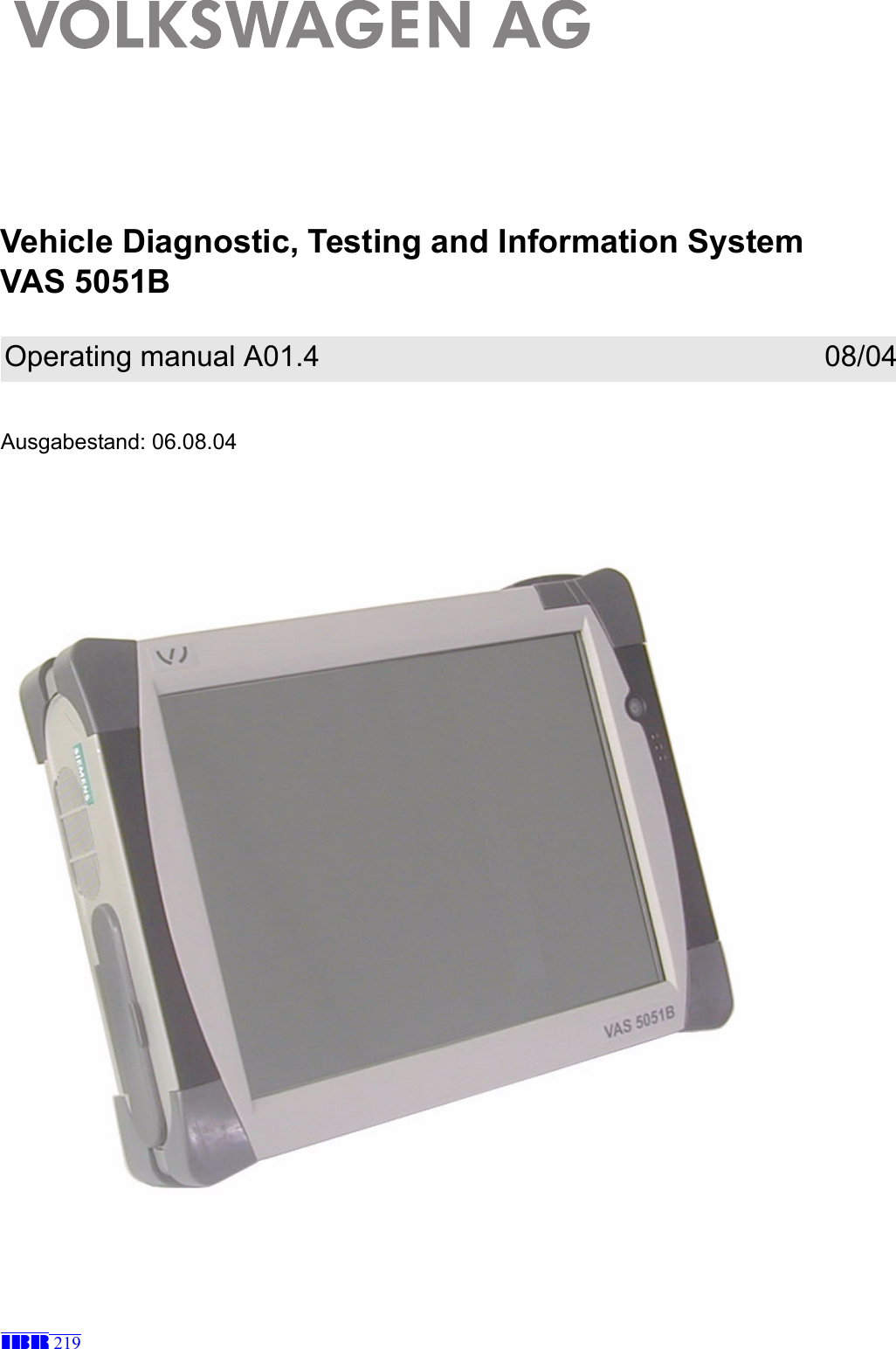
Siemens VAS5051B Car Diagnostic System with Bluetooth User Manual 219 GB A01 3 VAS 5051B UL Abnahme
Siemens AG Car Diagnostic System with Bluetooth 219 GB A01 3 VAS 5051B UL Abnahme
UserManual.wiki
>
Siemens
>
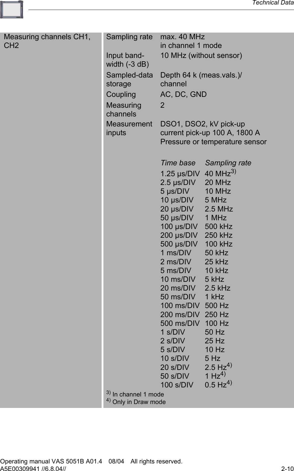
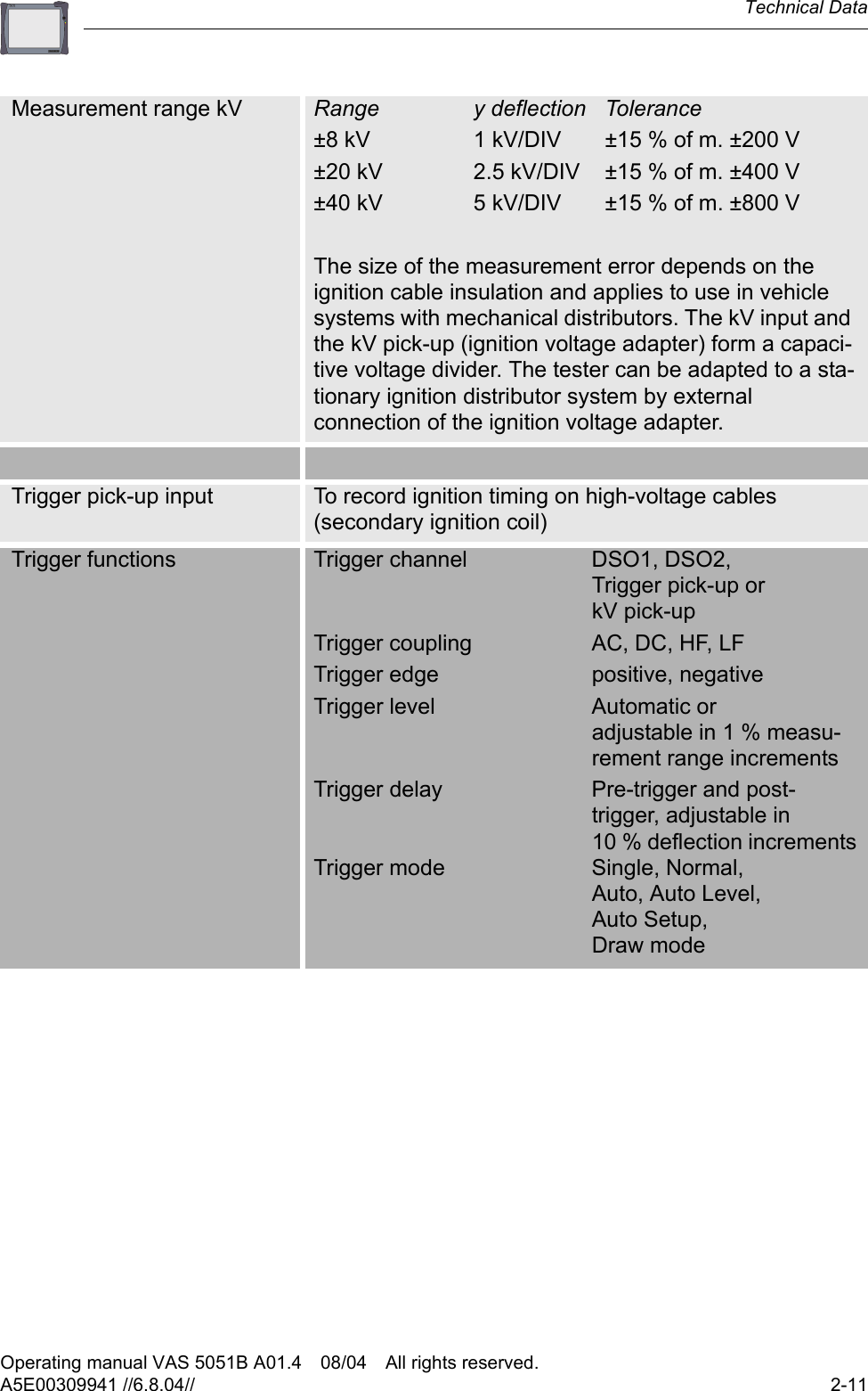
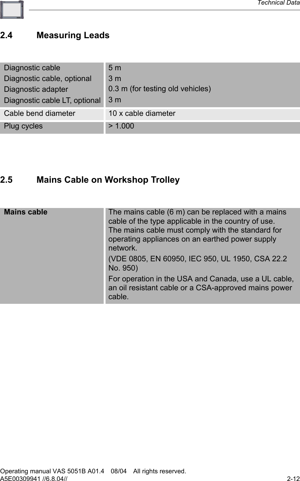
VAS5051B User Manual
VAS5051B User manual
Navigation menu
Upload a User Manual
Namespaces
Wiki Guide
HTML
PDF
Info
Views
User Manual
Discussion / Help
Navigation