Sierra Wireless MC5725 EVDO Mini-PCI Express Card CDMA Modem Module User Manual FCC submission HW Integration Guide
Sierra Wireless Inc. EVDO Mini-PCI Express Card CDMA Modem Module FCC submission HW Integration Guide
Contents
- 1. Quick Start Guide
- 2. Hardware Integration Guide
- 3. Users Manual
Users Manual
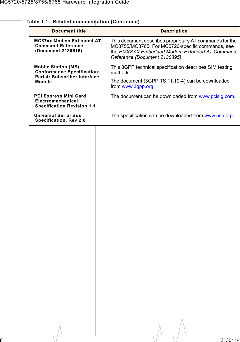

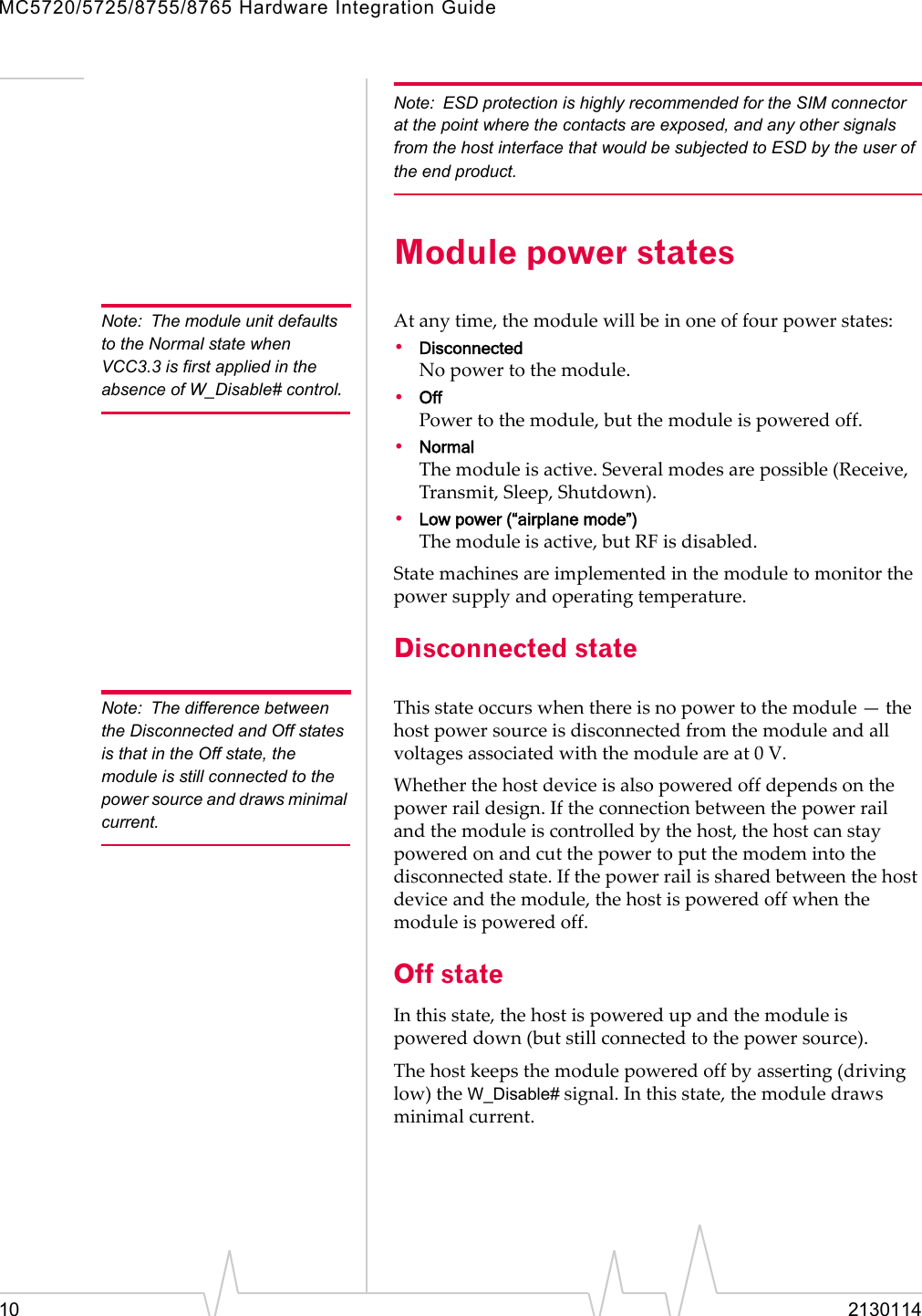
![Power InterfaceRev 1.1 Mar.06 11Normal stateNote: This is the default state when VCC3.3 is first applied in the absence of W_Disable# control.Thisistheactivestateofthemodule.Whileinthisstate:•Themoduleisfullypowered.•Themoduleiscapableofplacing/receivingcallsorestab‐lishingdataconnectionsonthewirelessnetwork.•TheUSBinterfaceisfullyactive.Low power modeInthispowerstate,RF(bothRxandTx)isdisabledinthemodule,buttheUSBinterfaceisstillactive.Thislowpowermode(ʺairplanemodeʺ)iscontrolledbyasoftwarecommandthroughthehostinterface.Forinstructionsonusingappropriatecommands,refertoATCommandSetforUserEquipment(UE)(Release6)(+CFUN=0command),EM5625/MC5720CnSReference(Document2130643)(CNS_RADIO_POWER[0x1075]),orMC87xxModemCnSReference(Document2130602)(DisableModem).Usage modelsUsagemodelscanbeusedtocalculateexpectedcurrentconsumption.AsampleusagemodelisprovidedinTable 2‐1Table 2-1: Power consumption of a sample applicationUsed by a field worker (data only)Used for remote data loggingUpload (module Tx)1000 kB/day 40 kB/hDownload (module Rx)500 kB/day 100 kB/dayCoverage / data rate1X / 80 kbps IS-95 / 14.4 kbpsHours of operation8 / day (off 16 hrs/day) 24 / dayTotal power consumed over 24 hours60 mAh 200 mAh](https://usermanual.wiki/Sierra-Wireless/MC5725.Users-Manual/User-Guide-661248-Page-13.png)