Sierra Wireless MC5725 EVDO Mini-PCI Express Card CDMA Modem Module User Manual FCC submission HW Integration Guide
Sierra Wireless Inc. EVDO Mini-PCI Express Card CDMA Modem Module FCC submission HW Integration Guide
Contents
- 1. Quick Start Guide
- 2. Hardware Integration Guide
- 3. Users Manual
Users Manual
2130114
Rev 1.1
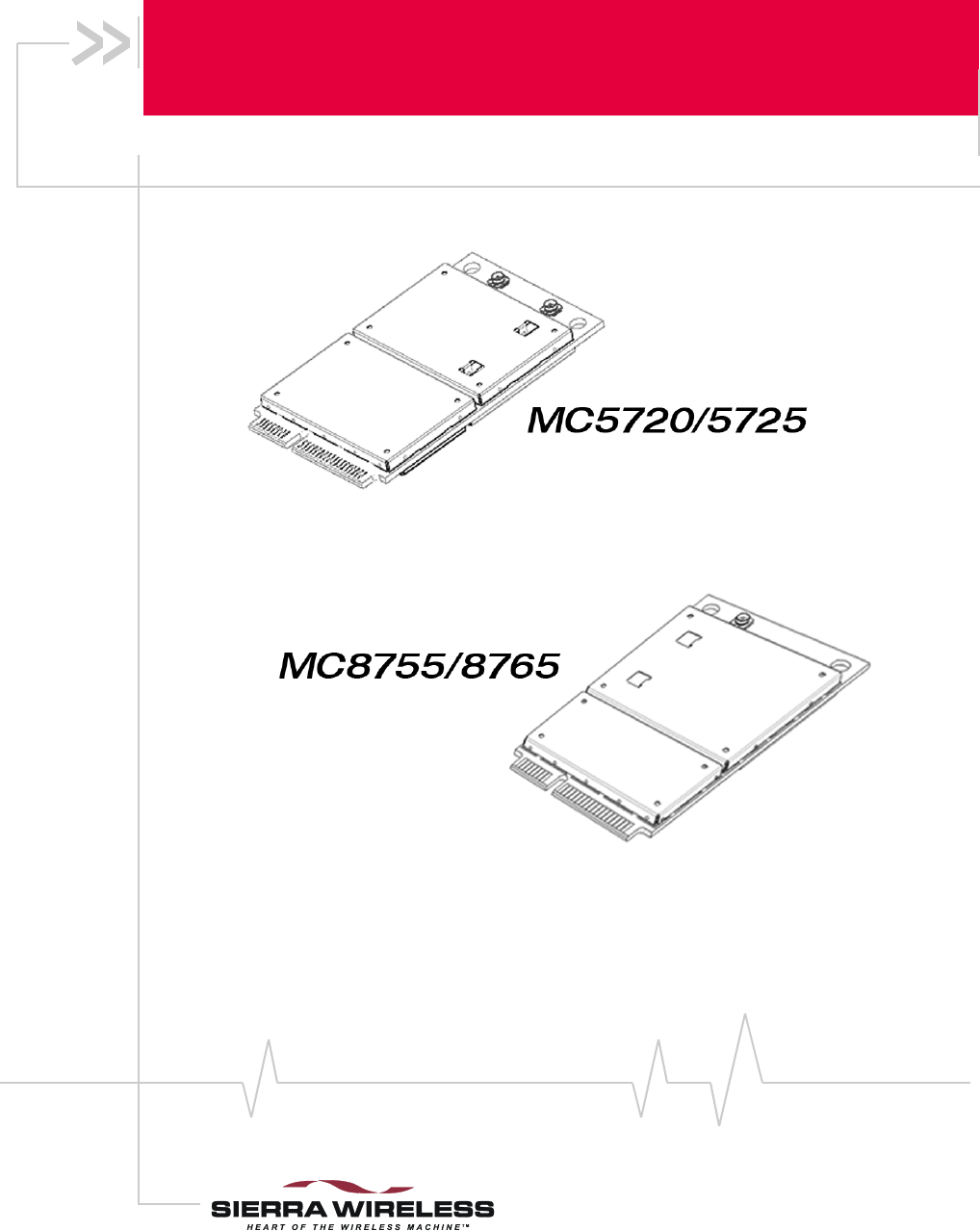
MC5720, MC5725, MC8755, MC8765
MiniCard
Hardware Integration Guide
Proprietary and Confidential
Preface
Rev 1.1 Mar.06 1
Limitation of
Liability
Theinformationinthismanualissubjecttochangewithout
noticeanddoesnotrepresentacommitmentonthepartof
SierraWireless.SIERRAWIRELESSANDITSAFFILIATES
SPECIFICALLYDISCLAIMLIABILITYFORANYANDALL
DIRECT,INDIRECT,SPECIAL,GENERAL,INCIDENTAL,
CONSEQUENTIAL,PUNITIVEOREXEMPLARYDAMAGES
INCLUDING,BUTNOTLIMITEDTO,LOSSOFPROFITSOR
REVENUEORANTICIPATEDPROFITSORREVENUE
ARISINGOUTOFTHEUSEORINABILITYTOUSEANY
SIERRAWIRELESSPRODUCT,EVENIFSIERRAWIRELESS
AND/ORITSAFFILIATESHASBEENADVISEDOFTHE
POSSIBILITYOFSUCHDAMAGESORTHEYARE
FORESEEABLEORFORCLAIMSBYANYTHIRDPARTY.
Notwithstandingtheforegoing,innoeventshallSierra
Wirelessand/oritsaffiliatesaggregateliabilityarisingunderor
inconnectionwiththeSierraWirelessproduct,regardlessof
thenumberofevents,occurrences,orclaimsgivingriseto
liability,beinexcessofthepricepaidbythepurchaserforthe
SierraWirelessproduct.
Patents Portionsofthisproductmaybecoveredbysomeorallofthe
followingUSpatents:
5,515,013 5,629,960 5,845,216 5,847,553 5,878,234
5,890,057 5,929,815 6,169,884 6,191,741 6,199,168
6,339,405 6,359,591 6,400,336 6,643,501 6,516,204
6,561,851 6,653,979 6,697,030 6,785,830 6,845,249
6,847,830 6,876,697 6,879,585 6,886,049 6,968,171
6,985,757 D442,170 D459,303
andotherpatentspending.
Thisproductincludes
technologylicensedfrom:
LicensedbyQUALCOMMIncorporatedunderoneormoreof
thefollowingUnitedStatespatentsand/ortheircounterparts
inothernations:
4,901,307 5,056,109 5,101,501 5,109,390 5,228,054
5,267,261 5,267,262 5,337,338 5,414,796 5,416,797
5,490,165 5,504,773 5,506,865 5,511,073 5,535,239
5,544,196 5,568,483 5,600,754 5,657,420 5,659,569
5,710,784 5,778,338
ManufacturedorsoldbySierraWirelessoritslicenseesunder
oneormorepatentslicensedfromInterDigitalGroup.
Copyright ©2006SierraWireless.Allrightsreserved.
MC5720/5725/8755/8765 Hardware Integration Guide
22130114
Trademarks AirCardand“HeartoftheWirelessMachine”areregistered
trademarksofSierraWireless.
SierraWireless,theSierraWirelesslogo,theredwavedesign,
thered‐tippedantenna,andWatcheraretrademarksofSierra
Wireless.
Windows®isaregisteredtrademarkofMicrosoftCorporation.
Qualcomm®isaregisteredtrademarkofQualcommIncorpo‐
rated.
Othertrademarksarethepropertyoftherespectiveowners.
Contact
Information
Consultourwebsiteforup‐to‐dateproductdescriptions,
documentation,applicationnotes,firmwareupgrades,trouble‐
shootingtips,andpressreleases:
www.sierrawireless.com
Sales Desk: Phone: 1-604-232-1488
Hours: 8:00 AM to 5:00 PM Pacific Time
E-mail: sales@sierrawireless.com
Post: Sierra Wireless
13811 Wireless Way
Richmond, BC
Canada V6V 3A4
Fax: 1-604-231-1109
Web: www.sierrawireless.com

Rev 1.1 Mar.06 3
Table of Contents
Introduction . . . . . . . . . . . . . . . . . . . . . . . . . . . . . . . . . . . . . . . . . . . . . . .5
The Universal Development Kit . . . . . . . . . . . . . . . . . . . . . . . . . . . . . . . . . . . . . . 5
Required connectors . . . . . . . . . . . . . . . . . . . . . . . . . . . . . . . . . . . . . . . . . . . . . . . 5
Guide organization . . . . . . . . . . . . . . . . . . . . . . . . . . . . . . . . . . . . . . . . . . . . . . . . . 6
Related documents. . . . . . . . . . . . . . . . . . . . . . . . . . . . . . . . . . . . . . . . . . . . . . . . . 6
Power Interface . . . . . . . . . . . . . . . . . . . . . . . . . . . . . . . . . . . . . . . . . . . .9
Overview of operation. . . . . . . . . . . . . . . . . . . . . . . . . . . . . . . . . . . . . . . . . . . . . . . 9
Power signals . . . . . . . . . . . . . . . . . . . . . . . . . . . . . . . . . . . . . . . . . . . . . . . . . . 9
Electrostatic discharge (ESD) . . . . . . . . . . . . . . . . . . . . . . . . . . . . . . . . . . . . 9
Module power states . . . . . . . . . . . . . . . . . . . . . . . . . . . . . . . . . . . . . . . . . . . . . . 10
Disconnected state . . . . . . . . . . . . . . . . . . . . . . . . . . . . . . . . . . . . . . . . . . . . 10
Off state . . . . . . . . . . . . . . . . . . . . . . . . . . . . . . . . . . . . . . . . . . . . . . . . . . . . . . 10
Normal state . . . . . . . . . . . . . . . . . . . . . . . . . . . . . . . . . . . . . . . . . . . . . . . . . . 11
Low power mode . . . . . . . . . . . . . . . . . . . . . . . . . . . . . . . . . . . . . . . . . . . . . . 11
Usage models . . . . . . . . . . . . . . . . . . . . . . . . . . . . . . . . . . . . . . . . . . . . . . . . . 11
RF Integration . . . . . . . . . . . . . . . . . . . . . . . . . . . . . . . . . . . . . . . . . . . .13
RF connection . . . . . . . . . . . . . . . . . . . . . . . . . . . . . . . . . . . . . . . . . . . . . . . . . . . . 13
Ground connection . . . . . . . . . . . . . . . . . . . . . . . . . . . . . . . . . . . . . . . . . . . . . . . . 13
Shielding . . . . . . . . . . . . . . . . . . . . . . . . . . . . . . . . . . . . . . . . . . . . . . . . . . . . . 14
Antenna and cabling . . . . . . . . . . . . . . . . . . . . . . . . . . . . . . . . . . . . . . . . . . . 14
Interference and sensitivity . . . . . . . . . . . . . . . . . . . . . . . . . . . . . . . . . . . . . . . . . 15
Power supply noise . . . . . . . . . . . . . . . . . . . . . . . . . . . . . . . . . . . . . . . . . . . . 15
Interference from other wireless devices . . . . . . . . . . . . . . . . . . . . . . . . . . 15
Device-generated RF . . . . . . . . . . . . . . . . . . . . . . . . . . . . . . . . . . . . . . . . . . . 16

MC5720/5725/8755/8765 Hardware Integration Guide
42130114
Host/Module Communication Interface . . . . . . . . . . . . . . . . . . . . . 17
LED output . . . . . . . . . . . . . . . . . . . . . . . . . . . . . . . . . . . . . . . . . . . . . . . . . . . 17
Regulatory Information . . . . . . . . . . . . . . . . . . . . . . . . . . . . . . . . . . . 19
Important notice . . . . . . . . . . . . . . . . . . . . . . . . . . . . . . . . . . . . . . . . . . . . . . . . . . 19
Safety and hazards . . . . . . . . . . . . . . . . . . . . . . . . . . . . . . . . . . . . . . . . . . . . . . . . 19
Important compliance information for North American users . . . . . . . . . . . 20
Acronyms and Definitions . . . . . . . . . . . . . . . . . . . . . . . . . . . . . . . . . 23
Index 25
1
Rev 1.1 Mar.06 5
1: Introduction
SierraWireless’MiniCardmodulesformtheradiocomponent
fortheproductsinwhichtheyareembedded.MiniCardsare
availableforuseonCDMAandGSMnetworks,including:
•MC5720andMC5725—operatesonCDMAnetworksusing
theIS‐95AandCDMA1X,and1xEV‐DO(IS‐866)network
standards
•MC8755andMC8765—operatesonGSMnetworksusing
theGSM/GPRS/EDGE/UMTS/HSDPAnetworkstandards
Purpose of this guide
ThisguideaddressesissuesthataffecttheintegrationofSierra
Wirelessmodulesintohostproducts,andincludesdesign
recommendationsforthehostproducts.
Note: An understanding of network technology and experience in
integrating hardware components into electronic equipment is
assumed.
The Universal Development Kit
SierraWirelessmanufacturesaUniversalDevelopmentKit
(UDK)thatfacilitatesallphasesoftheintegrationprocess.
Thiskitisahardwaredevelopmentplatformthatisdesigned
tosupportmultiplemembersoftheWirelessEmbedded
Moduleproductfamily.Itcontainsthehardwarecomponents
thataretypicallynecessaryforevaluatinganddevelopingwith
themodule,including:
•Developmentboard
•Cables
•Antennas
•Otheraccessories
Required connectors
Note: Contact vendors before
choosing your connectors — the
numbers included here are for
reference only. Choose
connectors that are appropriate
to your design.
Whenintegratingthesemodulesintoyourhostdevice,you
needthefollowingconnectortypes:
•RFcablethatmateswithHiroseU.FLconnector(model
U.FL #CL331‐0471‐0‐10)
•Industry‐standardmatingconnectorfor52‐pinEDGE:
SomemanufacturersincludeTyco,Foxconn,andMolex.For
example,theconnectorusedontheMC5720/MC5725/

MC5720/5725/8755/8765 Hardware Integration Guide
62130114
MC8755/MC8765UniversalDevelopmentKitboardisa
Molex67910‐0001.
•Industry‐standardUSIM/RUIMconnector:Theactual
connectoryouusedependsonhowyourdeviceexposesthe
USIM/RUIMsocket.Forexample,theUSIM/RUIM
connectorusedontheMC5720/MC5725/MC8755/MC8765
UniversalDevelopmentKitisanITTCCM03‐3518.
Guide organization
Thisguideincludesthefollowingsections:
1. Introduction(thissection)
2. Power Interface(p.9)
Describespowercontrolsignalsusedbythemoduleand
discussesdesignissuesrelatedtopowersupply
integration.
3. RF Integration(p.13)
Describesantennaconnectionmethodsandgroundingissues,
RFinterferenceanddesenseissues.
4. Host/Module Communication Interface(p.17)
DescribestheUSBinterfaceforhost/modulecommunication,
andtheUSIM/RUIMinterfaceforhost/moduleintegration.
5. Acronyms and Definitions(p.23)
Listsacronymsanddefinitionsusedthroughoutthisguide.
6. Regulatory Information(p.19)
Describesregulatoryapprovalsandregulatoryinformation
requirements.
Note: The term "host" always refers to the host device.
Related documents
Thisguidedealsspecificallywithhardwareintegrationissues
thatareuniquetotheMC5720/5725andMC8755/8765
modules.
Table 1‐1listsotherdocumentsreferencedinthisguide.
Introduction
Rev 1.1 Mar.06 7
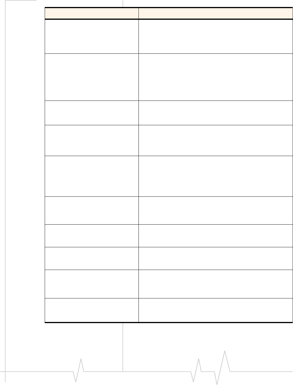
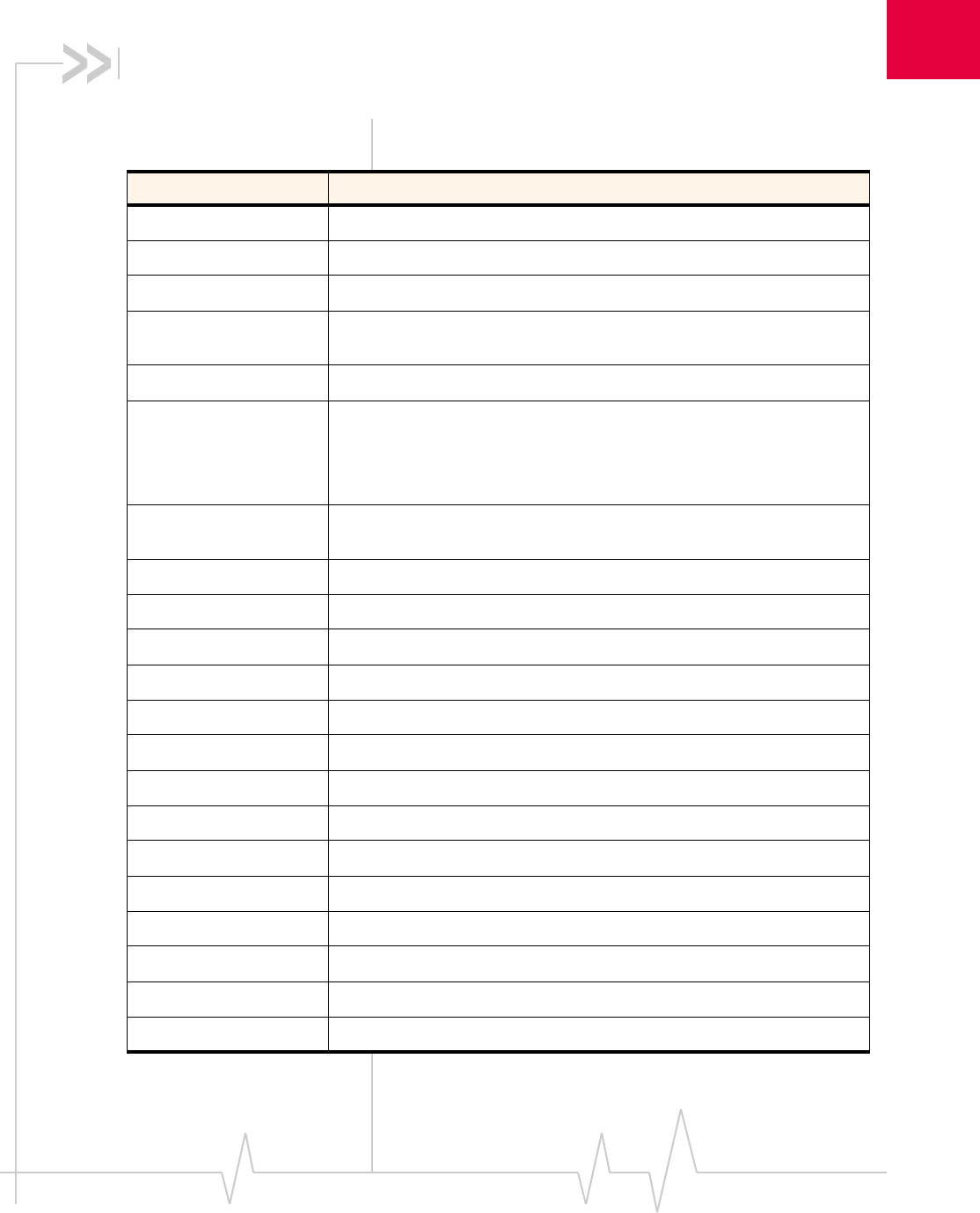
Table 1-1: Related documentation
Document title Description
AT Command Set for User
Equipment (UE) (Release 6)
This 3GPP technical specification describes standard AT
commands for GSM/UMTS devices.
The document (3GPP TS 27.007) can be downloaded
from www.3gpp.org.
CDMA 1X Standard This standard describes the technical requirements for
CDMA systems, including details on sleep cycle index
(SCI) values.
The document, CDMA 2000 Series Release A (2000)
(document # TIA/EIA/IS-2000 Series, Release A) can be
ordered from www.tiaonline.org.
EM5625/MC5720 CnS
Reference (Document
2130643)
This document describes the CnS (Control and Status)
messages that are available for use with the MC5720 and
the MC5725.
EMXXXX Embedded Modem
Extended AT Command
Reference (Document
2130395)
This document describes proprietary AT commands for the
MC5720. For MC8755/MC8765-specific commands, see
MC87xx Modem Extended AT Command Reference
(Document 2130616)
FCC Regulations - Part 15 -
Radio Frequency Devices
This section of the FCC Code of Federal Regulations, Title
47 deals with radio frequency devices, including EM
shielding requirements.
The regulation can be downloaded from
http://wireless.fcc.gov.
IEC-61000-4-2 level 3 This document describes techniques for testing and
measuring electrostatic discharge (ESD) immunity.
The document can be ordered from www.iec.ch.
MC5720 MiniCard Product
Specification (Document
2130599)
This document describes the mechanical and electrical
specifications, and standards compliance of the MC5720.
MC5725 MiniCard Product
Specification (Document
2130TBD)
This document describes the mechanical and electrical
specifications, and standards compliance of the MC5725.
MC8755/MC8765 PCI Express
MiniCard Product
Specification (Document
2130637)
This document describes the mechanical and electrical
specifications, and standards compliance of the MC8755/
MC8765.
MC87xx Modem CnS Reference
(Document 2130602)
This document describes the CnS (Control and Status)
messages that are available for use with the MC8755/
MC8765.
MC5720/5725/8755/8765 Hardware Integration Guide
82130114
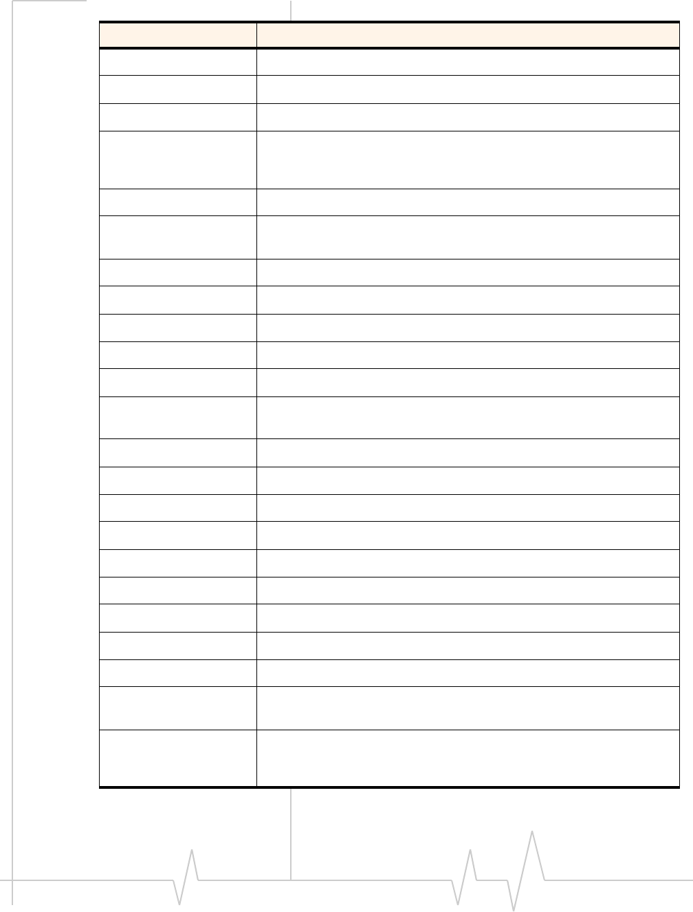
MC87xx Modem Extended AT
Command Reference
(Document 2130616)
This document describes proprietary AT commands for the
MC8755/MC8765. For MC5720-specific commands, see
the EMXXXX Embedded Modem Extended AT Command
Reference (Document 2130395)
Mobile Station (MS)
Conformance Specification;
Part 4: Subscriber Interface
Module
This 3GPP technical specification describes SIM testing
methods.
The document (3GPP TS 11.10-4) can be downloaded
from www.3gpp.org.
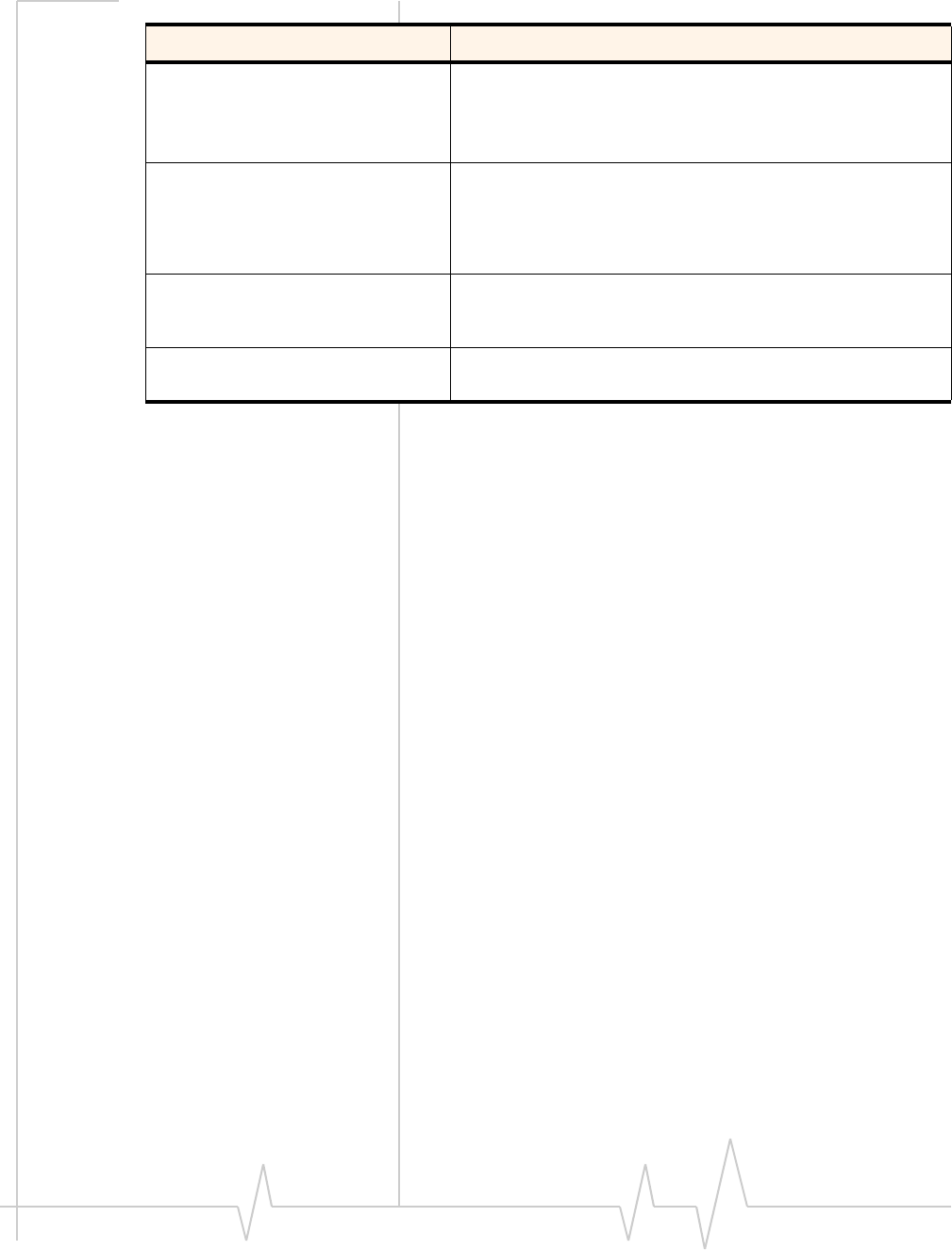
PCI Express Mini Card
Electromechanical
Specification Revision 1.1
The document can be downloaded from www.pcisig.com.
Universal Serial Bus
Specification, Rev 2.0
The specification can be downloaded from www.usb.org.
Table 1-1: Related documentation (Continued)
Document title Description

2
Rev 1.1 Mar.06 9
2: Power Interface
Overview of operation
Note: This chapter contains information for both the CDMA (MC5720/
5725) and GSM (MC8755/8765) modules.
Information that is unique to one module type is clearly identified.
Themoduleisdesignedtousea3.3V(nominal)powersupply,
providedbythehost.Itisthehost’sresponsibilitytoprovide
safeandcontinuouspowertothemoduleatalltimes;the
moduledoesNOThaveanindependentpowersupply,or
protectioncircuitstoguardagainstelectricalissues.
Themodule’spowerstateiscontrolledbythehost’sassertion/
de‐assertionoftheW_Disable#signal.Themodulealso
monitorsitssupplyvoltageandrequestsshutdownifthe
supplyisinsufficient.
Power signals
Themodulemustbeconnectedtoa3.3Vpowersupply(as
indicatedinPCIExpressMiniCardElectromechanicalSpecifi‐
cationRevision1.1).
TheMC8755/8765hasmorepowerpinsthantheMC5720/5725
duetohigherpeakcurrentrequirementsforGSMdevices.
Fordetailedpinoutandvoltage/currentrequirementsofthese
modules,seetheProductSpecificationdocumentforyour
MiniCard.
Electrostatic discharge (ESD)
Youareresponsibleforensuringthatthehosthasadequate
ESDprotectionondigitalcircuitsandantennaports:
•(Operational)RFport(antennalaunchandRFconnector):
IEC‐61000‐4‐2—Level(ElectrostaticDischargeImmunityTest)
•(Non‐operational)Hostconnectorinterface:
JESD22‐A114‐B+/‐1kVHumanBodyModeland
JESD22‐C101 +/‐125 VChargedDeviceModel
Specificrecommendationsareprovidedwhereneededinthis
guide,however,thelevelofprotectionrequireddependson
yourapplication.

MC5720/5725/8755/8765 Hardware Integration Guide
10 2130114
Note: ESD protection is highly recommended for the SIM connector
at the point where the contacts are exposed, and any other signals
from the host interface that would be subjected to ESD by the user of
the end product.
Module power states
Note: The module unit defaults
to the Normal state when
VCC3.3 is first applied in the
absence of W_Disable# control.
Atanytime,themodulewillbeinoneoffourpowerstates:
•Disconnected
Nopowertothemodule.
•Off
Powertothemodule,butthemoduleispoweredoff.
•Normal
Themoduleisactive.Severalmodesarepossible(Receive,
Transmit,Sleep,Shutdown).
•Low power (“airplane mode”)
Themoduleisactive,butRFisdisabled.
Statemachinesareimplementedinthemoduletomonitorthe
powersupplyandoperatingtemperature.
Disconnected state
Note: The difference between
the Disconnected and Off states
is that in the Off state, the
module is still connected to the
power source and draws minimal
current.
Thisstateoccurswhenthereisnopowertothemodule—the
hostpowersourceisdisconnectedfromthemoduleandall
voltagesassociatedwiththemoduleareat0V.
Whetherthehostdeviceisalsopoweredoffdependsonthe
powerraildesign.Iftheconnectionbetweenthepowerrail
andthemoduleiscontrolledbythehost,thehostcanstay
poweredonandcutthepowertoputthemodemintothe
disconnectedstate.Ifthepowerrailissharedbetweenthehost
deviceandthemodule,thehostispoweredoffwhenthe
moduleispoweredoff.
Off state
Inthisstate,thehostispoweredupandthemoduleis
powereddown(butstillconnectedtothepowersource).
Thehostkeepsthemodulepoweredoffbyasserting(driving
low)theW_Disable#signal.Inthisstate,themoduledraws
minimalcurrent.
Power Interface
Rev 1.1 Mar.06 11
Normal state
Note: This is the default state
when VCC3.3 is first applied in
the absence of W_Disable#
control.
Thisistheactivestateofthemodule.Whileinthisstate:
•Themoduleisfullypowered.
•Themoduleiscapableofplacing/receivingcallsorestab‐
lishingdataconnectionsonthewirelessnetwork.
•TheUSBinterfaceisfullyactive.
Low power mode
Inthispowerstate,RF(bothRxandTx)isdisabledinthe
module,buttheUSBinterfaceisstillactive.Thislowpower
mode(ʺairplanemodeʺ)iscontrolledbyasoftwarecommand
throughthehostinterface.
Forinstructionsonusingappropriatecommands,refertoAT
CommandSetforUserEquipment(UE)(Release6)(+CFUN=0
command),EM5625/MC5720CnSReference(Document2130643)
(CNS_RADIO_POWER[0x1075]),orMC87xxModemCnS
Reference(Document2130602)(DisableModem).
Usage models
Usagemodelscanbeusedtocalculateexpectedcurrent
consumption.AsampleusagemodelisprovidedinTable 2‐1
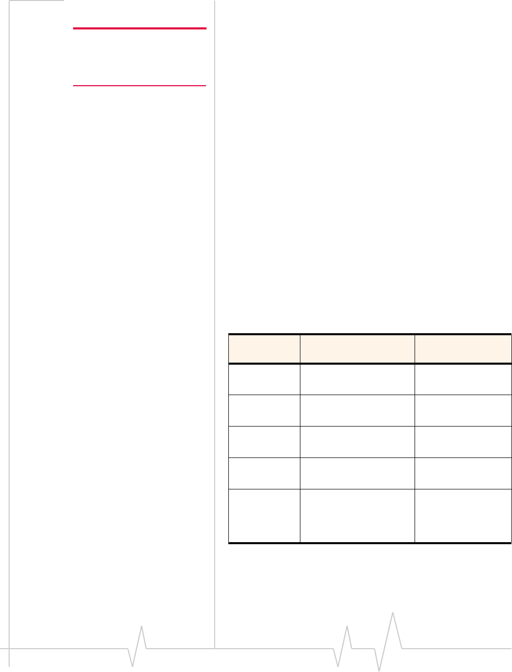
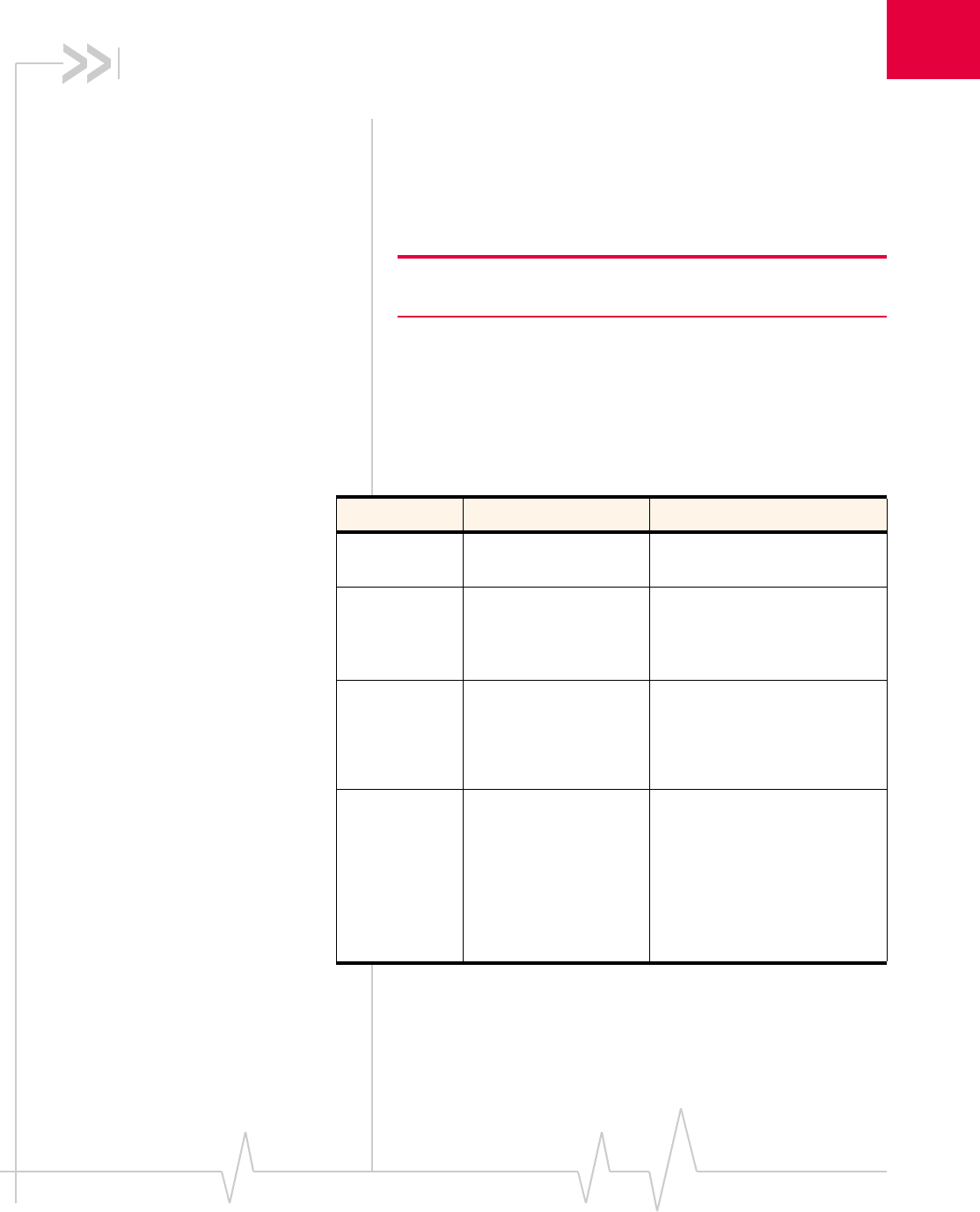
Table 2-1: Power consumption of a sample application
Used by a field
worker (data only)
Used for remote
data logging
Upload
(module Tx)
1000 kB/day 40 kB/h
Download
(module Rx)
500 kB/day 100 kB/day
Coverage /
data rate
1X / 80 kbps IS-95 / 14.4 kbps
Hours of
operation
8 / day (off 16 hrs/day) 24 / day
Total power
consumed
over 24
hours
60 mAh 200 mAh

MC5720/5725/8755/8765 Hardware Integration Guide
12 2130114
Thisexamplemodelappliestoabattery‐operateddevice.In
practice,becausethemodulewillbeisolatedfromthebattery
(thehostdevicemanagesthepowersource),themAhratings
willdependonthedevice’ssupplyefficiency.
Themoduleautomaticallyentersslottedsleepmodewhen
thereisnotransmissionorreceptionoccurring(SCI=2).
Transmitpowerisassumedtobe+3dBm.
3
Rev 1.1 Mar.06 13
3: RF Integration
RF connection
Considerthefollowingwhenattachinganantennatothe
module:
Note: To disconnect the
antenna, make sure you use the
Hirose U.FL connector removal
tool (P/N UFL-LP-N-2(01) to
prevent damage to the module
or coaxial cable assembly.
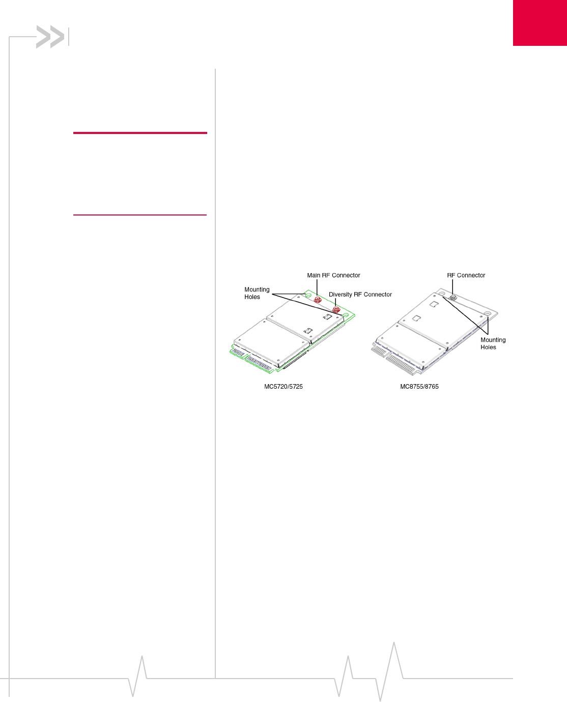
•UseaHiroseU.FLconnector(model
U.FL #CL331‐0471‐0‐10)toattachanantennatoa
connectionpointonthemodule,asshowninFigure 3‐1
(ThemainRFconnectoronthetopside;thediversityRF
connectoronthebottomside).
•Matchcoaxialconnectionsbetweenthemoduleandthe
antennato50 Ω.
•MinimizeRFcablelossestotheantenna;therecommended
maximumcablelossforantennacablingis0.5 dB.
Figure 3-1: Antenna connection points and mounting holes
Ground connection
Whenconnectingthemoduletosystemground:
•Preventnoiseleakagebyestablishingaverygoodground
connectiontothemodulethroughthehostconnector.
•Connecttosystemgroundusingthetwomountingholesat
thetopofthemodule(asshowninFigure 3‐1).
•MinimizegroundnoiseleakageintotheRF.
Dependingonthehostboarddesign,noisecouldpotentially
becoupledtothemodulefromthehostboard.Thisis
mainlyanissueforhostdesignsthathavesignalstraveling
alongthelengthofthemodule,orcircuitryoperatingat
bothendsofthemoduleinterconnects.

MC5720/5725/8755/8765 Hardware Integration Guide
14 2130114
Shielding
ThemoduleisfullyshieldedtoprotectagainstEMIandto
ensurecompliancewithFCCPart15‐“RadioFrequency
Devices”(orequivalentregulationsinotherjurisdictions).
Note: The module shields must NOT be removed.
Antenna and cabling
Whenselectingtheantennaandcable,itiscriticaltoRFperfor‐
mancetomatchantennagainandcableloss.
Choosing the correct antenna and cabling
Considerthefollowingpointsforpropermatchingofantennas
andcabling:
•Theantenna(andassociatedcircuitry)shouldhavea
nominalimpedanceof50 Ωwithareturnloss ≤10 dB
acrosseachfrequencybandofoperation.
•Thesystemgainvalueaffectsbothradiatedpowerand
regulatory(FCC,IC,CE,etc.)testresults.
Developing custom antennas
Considerthefollowingpointswhendevelopingcustom‐
designedantennas:
•AskilledRFengineershoulddothedevelopmenttoensure
thattheRFperformanceismaintained.
•Identifythebandsthatneedtobesupported,particularly
whenboththeMC5720/5725andMC8755/8765willbe
installedinthesameplatform.Inthiscase,youmaywantto
developseparateantennasformaximumperformance.
Determining the antenna’s location
Considerthefollowingpointswhendecidingwheretoputthe
antenna:
•AntennalocationmayaffectRFperformance.Althoughthe
moduleisshieldedtopreventinterferenceinmostapplica‐
tions,theplacementoftheantennaisstillveryimportant—
ifthehostdeviceisinsufficientlyshielded,highlevelsof
broadbandorspuriousnoisecandegradethemodule’s
performance.
•Connectingcablesbetweenthemoduleandtheantenna
musthave50 Ωimpedance.Iftheimpedanceofthemodule
ismismatched,RFperformanceisreducedsignificantly.
•Antennacablesshouldberouted,ifpossible,awayfrom
noisesources(switchingpowersupplies,LCDassemblies,

RF Integration
Rev 1.1 Mar.06 15
etc.).Ifthecablesarenearthenoisesources,thenoisemay
becoupledintotheRFcableandintotheantenna.
Disabling the diversity antenna (MC5720/5725)
IfyourhostdeviceisnotdesignedtousetheMC5720/5725’s
diversityantenna,terminatetheinterfacewithano‐connect.
Interference and sensitivity
Note: These modules are based
on ZIF (Zero Intermediate
Frequency) technologies; when
performing EMC
(Electromagnetic Compatibility)
tests, there are no IF
(Intermediate Frequency)
components from the module to
consider.
SeveralsourcesofinterferencecanaffecttheRFperformance
ofthemodule(RF desense).Commonsourcesincludepower
supplynoiseanddevice‐generatedRF.
RF desensecanbeaddressedthroughacombinationof
mitigationtechniquesandradiatedsensitivitymeasurement.
Power supply noise
NoiseinthepowersupplycanleadtonoiseintheRFsignal.
Thepowersupplyripplelimitforthemoduleisnomorethan
200 mVp‐p1Hzto100 kHz.Thislimitincludesvoltageripple
duetotransmitterburstactivity
Interference from other wireless devices
Differentwirelessdevicesoperatinginsidethehostdevicecan
causeinterferencethataffectsthemodule.
Todeterminethemostsuitablelocationsforeachantennaon
yourhostdevice,evaluateeachwirelessdevice’sradiosystem,
consideringthefollowing:
•Anyharmonics,sub‐harmonics,orcross‐productsofsignals
generatedbywirelessdevicesthatfallinthemodule’sRx
rangemaycausespuriousresponseresultingindecreased
Rxperformance.
•TheTxpowerandcorrespondingbroadbandnoiseofother
wirelessdevicesmayoverloadorincreasethenoisefloorof
themodule’sreceiver,resultinginRxdesense.
Theseverityofthisinterferencedependsontheclosenessof
theotherantennastothemodule’santenna.Todetermine
suitablelocationsforeachwirelessdevice’santenna,
thoroughlyevaluateyourhostdevice’sdesign.

MC5720/5725/8755/8765 Hardware Integration Guide
16 2130114
Device-generated RF
Note: The module can cause
interference with other devices
such as hearing aids and on-
board speakers.
Wireless devices such as the
MiniCard transmit in bursts
(pulse transients), for set
durations (RF burst frequencies).
Hearing aids and speakers
convert these burst frequencies
into audible frequencies,
resulting in audible noise.
AllelectroniccomputingdevicesgenerateRFinterferencethat
cannegativelyaffectthereceivesensitivityofthemodule
(RF desense).
Theproximityofhostelectronicstotheantennainwireless
devicescancontributetoRF desense.Componentsthatare
mostlikelytocauseRF desenseinclude:
•Microprocessorandmemory
•Displaypanelanddisplaydrivers
•Switching‐modepowersupplies
These,andotherhigh‐speeddevices(inparticular,the
processor)cancauseRF desensebecausetheyrunat
frequenciesoftensofMHz.Therapidriseandfallofthese
clocksignalsgenerateshigher‐orderharmonicsthatoftenfall
withintheoperatingfrequencybandofthemodule,causing
RF desense.
Example
Onasub‐systemrunningat40MHz,the22ndharmonicfalls
at880MHz,whichiswithinthecellularreceivefrequency
band.
Note: In practice, there are usually numerous interfering frequencies
and harmonics. The net effect can be a series of desensitized receive
channels.
4
Rev 1.1 Mar.06 17
4: Host/Module Communication
Interface
ThischapterprovidesinformationabouttheHost‐Module
communicationinterface(USBinterface)andlistsofextended
ATcommandsthatmaybeusefulforhardwareintegration
testing.
Note: On any given interface (USB, USIM/RUIM, etc.), leave unused
inputs and outputs as no-connects.
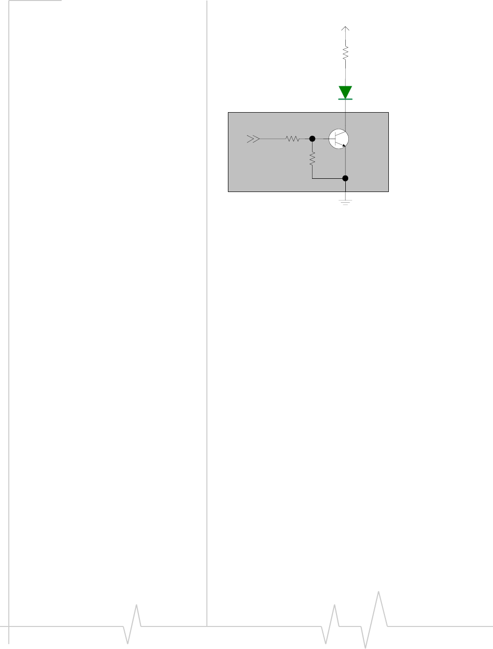
LED output
ThemoduledrivestheLEDoutputaccordingtothePCI‐
ExpressMiniCardspecification(summarizedinTable 4‐1,
below).
Table 4-1: LED States
State Indicates Characteristics
OFF Module is not
powered.
Light is turned off.
ON Module is powered
and connected, but
not transmitting or
receiving.
Light is turned on.
Slow Blink Module is powered
and searching for a
connection.
LED is flashing at a steady,
slow rate.
•250 ms ± 25% ON period
•0.2 Hz ± 25% blink rate
Intermittent
Blink
Module is transmitting
or receiving.
LED is flashing
intermittently, proportional to
activity on the interface.
•50% duty cycle
•3 Hz minimum blink rate
•20 Hz maximum blink
rate
MC5720/5725/8755/8765 Hardware Integration Guide
18 2130114
Figure 4-1: Example LED
Current limiting Resistor
LED
VCC 3.3V
MIO
MiniCard

5
Rev 1.1 Mar.06 19
5: Regulatory Information
Important notice
Becauseofthenatureofwirelesscommunications,trans‐
missionandreceptionofdatacanneverbeguaranteed.Data
maybedelayed,corrupted(i.e.,haveerrors)orbetotallylost.
Althoughsignificantdelaysorlossesofdataarerarewhen
wirelessdevicessuchastheSierraWirelessmodemareusedin
anormalmannerwithawell‐constructednetwork,theSierra
Wirelessmodemshouldnotbeusedinsituationswherefailure
totransmitorreceivedatacouldresultindamageofanykind
totheuseroranyotherparty,includingbutnotlimitedto
personalinjury,death,orlossofproperty.SierraWirelessand
itsaffiliatesacceptnoresponsibilityfordamagesofanykind
resultingfromdelaysorerrorsindatatransmittedorreceived
usingtheSierraWirelessmodem,orforfailureoftheSierra
Wirelessmodemtotransmitorreceivesuchdata.
Safety and hazards
DonotoperateyourMC5720/MC5725/MC8755/MC8765
modem:
•Inareaswhereblastingisinprogress
•Whereexplosiveatmospheresmaybepresentincluding
refuellingpoints,fueldepots,andchemicalplants
•Nearmedicalequipment
•Nearlifesupportequipment,oranyequipmentwhichmay
besusceptibletoanyformofradiointerference.Insuch
areas,theMC5720/MC5725/MC8755/MC8765modem
MUSTBEPOWEREDOFF.Otherwise,theMC5720/
MC5725/MC8755/MC8765modemcantransmitsignals
thatcouldinterferewiththisequipment.
Inanaircraft,theMC5720/MC5725/MC8755/MC8765modem
MUSTBEPOWEREDOFF.Otherwise,theMC5720/MC5725/
MC8755/MC8765modemcantransmitsignalsthatcould
interferewithvariousonboardsystemsandmaybedangerous
totheoperationoftheaircraftordisruptthecellularnetwork.
Useofacellularphoneinanaircraftisillegalinsomejurisdic‐
tions.Failuretoobservethisinstructionmayleadto
suspensionordenialofcellulartelephoneservicestothe
offender,orlegalactionorboth.

MC5720/5725/8755/8765 Hardware Integration Guide
20 2130114
Someairlinesmaypermittheuseofcellularphoneswhilethe
aircraftisonthegroundandthedoorisopen.TheMC5720/
MC5725/MC8755/MC8765modemmaybeusednormallyat
thistime.
Important compliance
information for North American
users
TheMC5720/MC5725/MC8755/MC8765modemhasbeen
grantedmodularapprovalformobileapplications.Integrators
mayusetheMC5720/MC5725/MC8755/MC8765modemin
theirfinalproductswithoutadditionalFCC / IC(Industry
Canada)certificationiftheymeetthefollowingconditions.
Otherwise,additionalFCC / ICapprovalsmustbeobtained.
1. Atleast20 cmseparationdistancebetweentheantennaand
theuser’sbodymustbemaintainedatalltimes.
2. TocomplywithFCC / ICregulationslimitingbothmaximum
RFoutputpowerandhumanexposuretoRFradiation,the
maximumantennagainincludingcablelossinamobile‐only
exposureconditionmustnotexceed:
·8dBiintheCellularbandand4dBiinthePCSbandforthe
MC8755/MC8765
·4.65 dBiintheCellularbandand3.35 dBiinthePCSband
fortheMC5720/MC5725
3. TheMC5720/MC5725/MC8755/MC8765modemandits
antennamustnotbeco‐locatedoroperatinginconjunction
withanyothertransmitterorantennawithinahostdevice.
4. Alabelmustbeaffixedtotheoutsideoftheendproductinto
whichtheMC5720/MC5725/MC8755/MC8765modemis
incorporated,withastatementsimilartothefollowing:
·ForMC5720:
ThisdevicecontainsTXFCCID:N7N‐MC5720
Thisequipmentcontainsequipmentcertifiedunder
IC: 2417C‐MC5720
·ForMC5725:
ThisdevicecontainsTXFCCID:N7N‐MC5725
Thisequipmentcontainsequipmentcertifiedunder
IC: 2417C‐MC5725
·ForMC8755:
ThisdevicecontainsTXFCCID:N7NMC8755
Thisequipmentcontainsequipmentcertifiedunder
IC: 2417C‐MC8755
·ForMC8765:
ThisdevicecontainsTXFCCID:N7NMC8765
Thisequipmentcontainsequipmentcertifiedunder
IC: 2417C‐MC8765

Regulatory Information
Rev 1.1 Mar.06 21
5. Ausermanualwiththeendproductmustclearlyindicatethe
operatingrequirementsandconditionsthatmustbeobserved
toensurecompliancewithcurrentFCC / ICRFexposure
guidelines.
TheendproductwithanembeddedMC5720/MC5725/
MC8755/MC8765modemmayalsoneedtopasstheFCCPart
15unintentionalemissiontestingrequirementsandbe
properlyauthorizedperFCCPart15.
Note:Ifthismoduleisintendedforuseinaportabledevice,
youareresponsibleforseparateapprovaltosatisfytheSAR
requirementsofFCCPart2.1093andICRSS‐102.

MC5720/5725/8755/8765 Hardware Integration Guide
22 2130114
A
Rev 1.1 Mar.06 23
A: Acronyms and Definitions
.
Table 5-1: Acronyms and definitions
Acronym or term Definition
AGC Automatic Gain Control
BER Bit Error Rate - a measure of receive sensitivity
BLER Block Error Rate
Call Box Base Station Simulator - Agilent E8285A or 8960, Rohde &
Schwarz CMU200
CDMA Code Division Multiple Access
dB Decibel = 10 x log10 (P1/P2)
P1 is calculated power; P2 is reference power
Decibel = 20 x log10 (V1/V2)
V1 is calculated voltage, V2 is reference voltage
dBm Decibels, relative to 1 mW - Decibel(mW) = 10 x log10 (Pwr (mW)/
1mW)
DUT Device Under Test
EDGE Enhanced Data rates for GSM Evolution
EM Embedded Module
ESD ElectroStatic Discharge
FER Frame Error Rate - a measure of receive sensitivity
GPRS General Packet Radio Service
GPS Global Positioning System
GSM Global System for Mobile communications
Hz Hertz = 1 cycle/second
inrush current Peak current drawn when a device is connected or powered on
IS-2000 3G radio standards for voice and data (CDMA only)
IS-95 2G radio standards targeted for voice (cdmaONE)
LDO Low Drop Out - refers to linear regulator
MC5720 / MC5725 Sierra Wireless MiniCards used on CDMA networks
MC5720/5725/8755/8765 Hardware Integration Guide
24 2130114
MC8755 / MC8765 Sierra Wireless MiniCards used on GSM networks
MHz MegaHertz = 10E6 Hertz (Hertz = 1 cycle/second)
MIO Module Input/Output
MPE Maximum Permissible Exposure — the level of radiation to which a
person may be exposed without hazardous effect or adverse
biological changes
OTA Over The Air or Radiated through the antenna
PCS Personal Communication System - PCS spans the 1.9 GHz radio
spectrum
RF Radio Frequency
RMS Root Mean Square
RUIM Removable User Identity Module
SA Selective Availability
Sensitivity (Audio) Measure of lowest power signal that the receiver can measure
Sensitivity (RF) Measure of lowest power signal at the receiver input that can
provide a prescribed BER/BLER/SNR value at the receiver output.
SIM Subscriber Identity Module
SNR Signal to Noise Ratio
SOF Start of Frame - a USB function
UART Universal Asynchronous Receiver Transmitter
UDK Universal Development Kit
UMTS Universal Mobile Telecommunications System
USB Universal Serial Bus
USIM Universal Subscriber Identity Module
VCC3.3 3.3 V supply voltage
WCDMA Wideband Code Division Multiple Access — In this document, the
term “UMTS” is used instead of “WCDMA”.
XIM In this document, XIM is used as part of the contact identifiers for
the USIM/RUIM interface (XIM_VCC, XIM_CLK, etc.). It indicates
either RUIM or USIM.
Table 5-1: Acronyms and definitions
Acronym or term Definition

Rev 1.1 Mar.06 25
Index
A
acronymsanddefinitions 23–24
airplanemode 11
antenna
connectionandmountingpoints 13
connectionconsiderations 13
custom,considerations 14
diversityantenna,disabling 15
limit,matchingcoaxialconnections 13
location,considerations 14
matching,considerations 14
maximumcableloss 13
ATcommands
3GPPspecification,details 7
extended,MC5720/5725 7
extended,MC8755/8765 8
lowpowermode,setting 11
C
cableloss
antenna,maximum 13
CnS
MC5720reference,details 7
MC8755reference,details 7
connection
grounding 13
connectors,required
EDGEmating(52‐pin) 5
host‐module 5–6
RF,Hirose 5
USIM/RUIM 6
current
consumption
usagemodels 11
D
defaultstate(Normal),module 11
desense.SeeRF
disconnected,modulepowerstate 10
diversityantenna
disabling 15
E
electrostaticdischarge.SeeESD
ESD
protectionrequirements 9–10
testingtechniquesdocument(IEC‐61000‐4‐2) 7
F
FCC
regulations,relevantsection 7
G
grounding
connectionconsiderations 13
groundloops,avoiding 14
H
Host⁄Moduleinterface 17–18
I
interference
devicegenerated 16
powersupplynoise 15
wirelessdevices 15
L
LED
example 18
state
intermittentblink 17
off 17
on 17
slowblink 17
lowpowermode
setting,ATcommands 11
lowpower,modulepowerstate 11
M
MC5720
CnSreference,details 7
productspecification 7
MC5720/5725
extendedATcommands 7
MC8755/8765
CnSreference,details 7
extendedATcommands 8
productspecification 7
minicard
PCIExpressSpecification,details 8
SeealsoMC5720⁄5725;MC8755⁄8765
module
powerstates 10–11
module,defaultpowermode(Normal) 11

MC5720/5725/8755/8765 Hardware Integration Guide
26 2130114
N
noise
leakage,minimizing 13
RFinterference,powersupply 15
normal,modulepowerstate 11
O
off,modulepowerstate 10
P
PCIExpress
minicardspecificationdetails 8
power
disconnected,characteristics 10
normal,characteristics 11
off,characteristics 10
signals,overview 9
state,disconnected 10
state,lowpower 11
state,normal 11
state,off 10
states,module 10–11
supply,RFinterference 15
powerinterface 9–12
ProductSpecificationDocument.SeePSD
PSD
MC5720⁄5725,details 7
MC8755/8765,details 7
R
regulatoryinformation
FCC 20
limitationofliability 19
safetyandhazards 19
RF
antennacableloss,maximum 13
antennaconnection,considerations 13
cabletype,required 5
desense
device‐generated 16
integration 13–16
interference
otherdevices 16
powersupply 15
wirelessdevices 15
S
shielding
module,compliance 14
SIM.SeeUSIM/RUIM
T
testing
ESDimmunity,techniquesdocument(IEC‐61000‐
4‐2) 7
U
UDK.SeeUniversalDevelopmentKit
UniversalDevelopmentKit
components,included 5
UniversalSerialBus.SeeUSB
usagemodels
currentconsumption 11
USB
specification,details 8
USIM/RUIM
connectortype,required 6
