Sierra Wireless MC5728 PCA,EVDO MINI-PCI EXPRESS CARD CDMA MODEM User Manual HW Integration Guide
Sierra Wireless Inc. PCA,EVDO MINI-PCI EXPRESS CARD CDMA MODEM HW Integration Guide
UserManual.wiki
>
Sierra Wireless
>
MC5728 User Manual
Manual
Navigation menu
Upload a User Manual
Namespaces
Wiki Guide
HTML
PDF
Info
Views
User Manual
Discussion / Help
Navigation
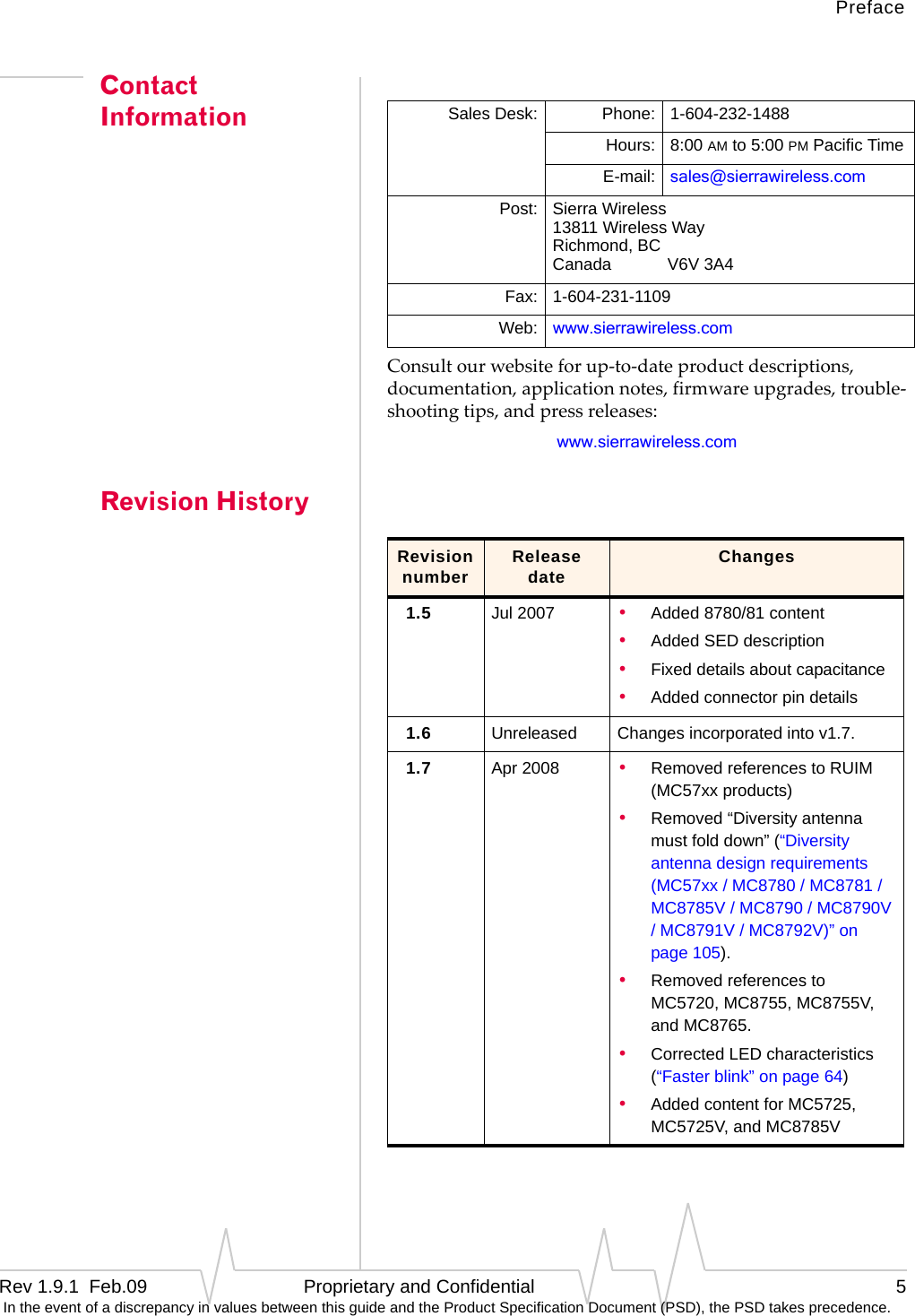
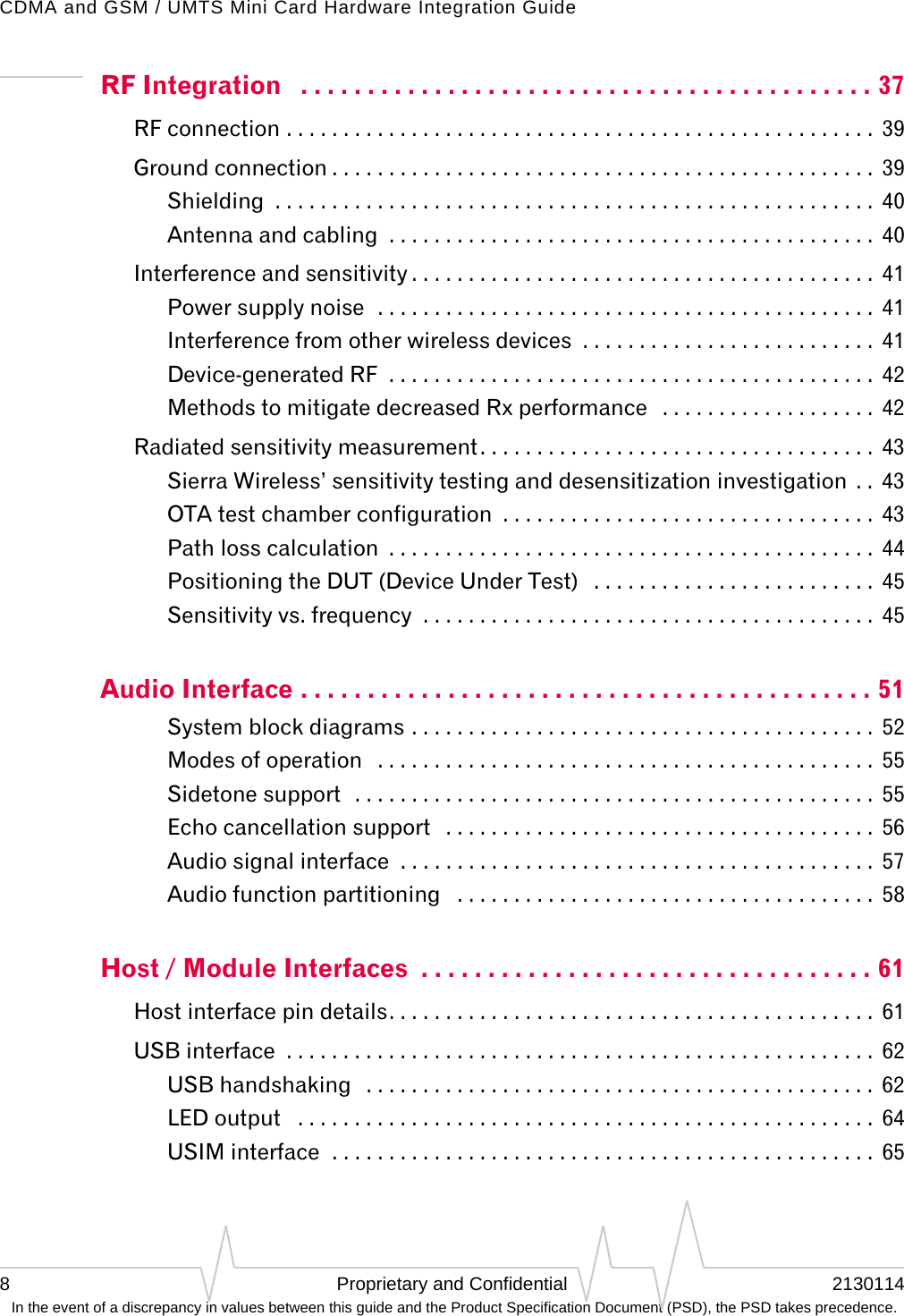
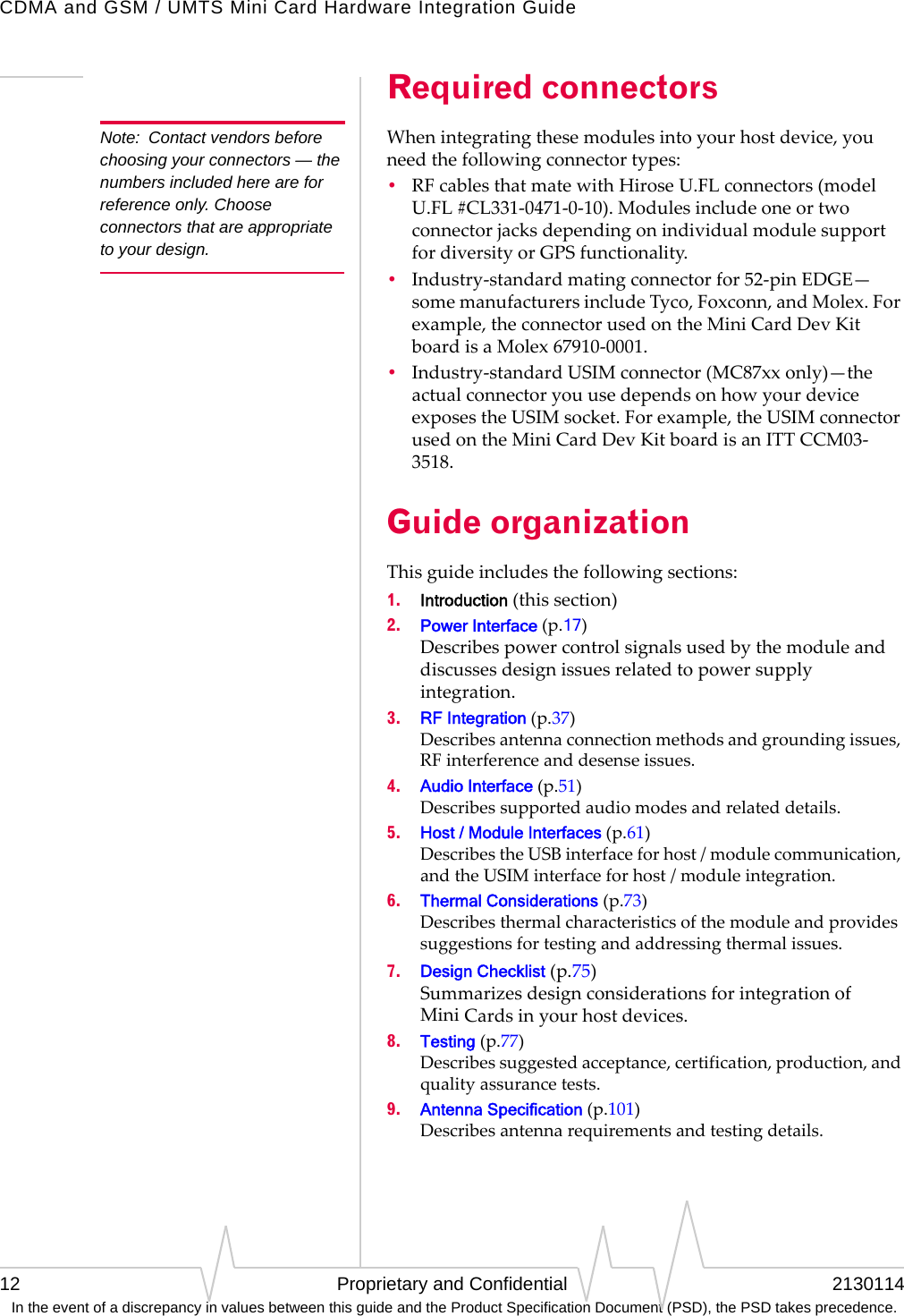
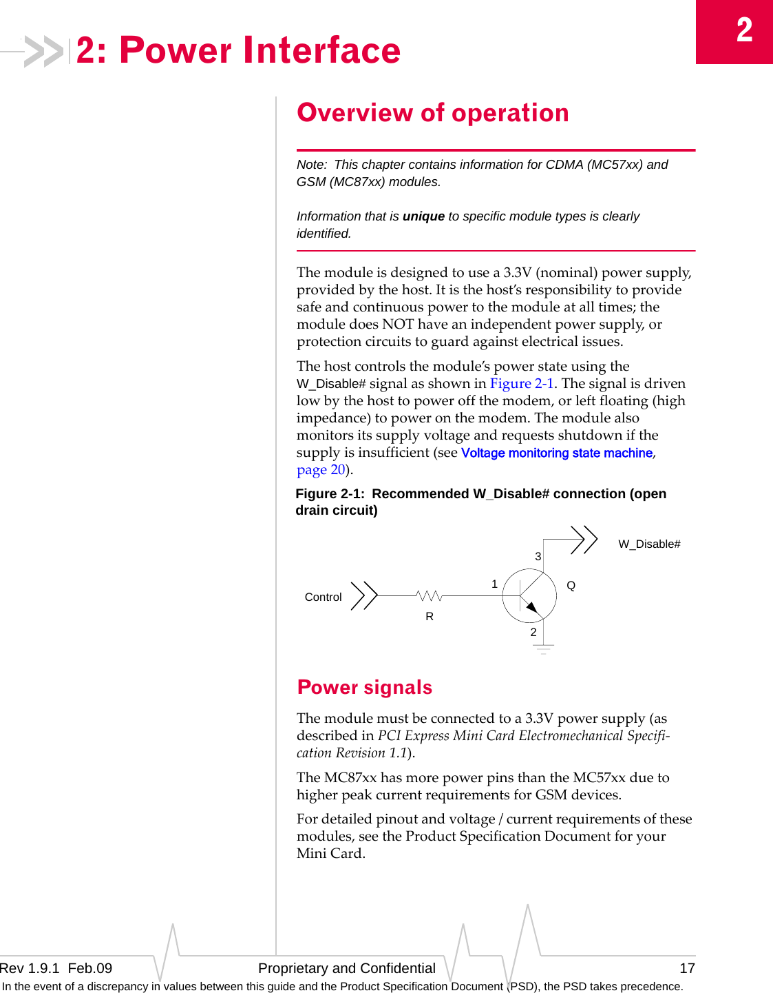
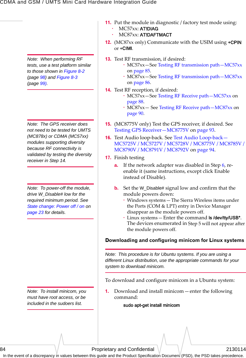
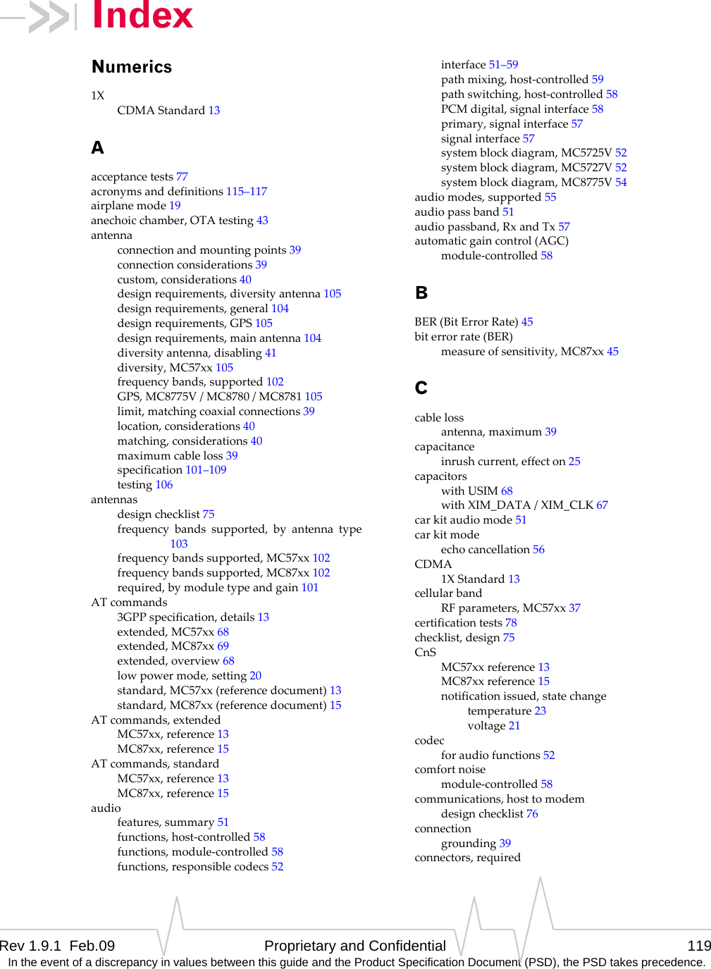
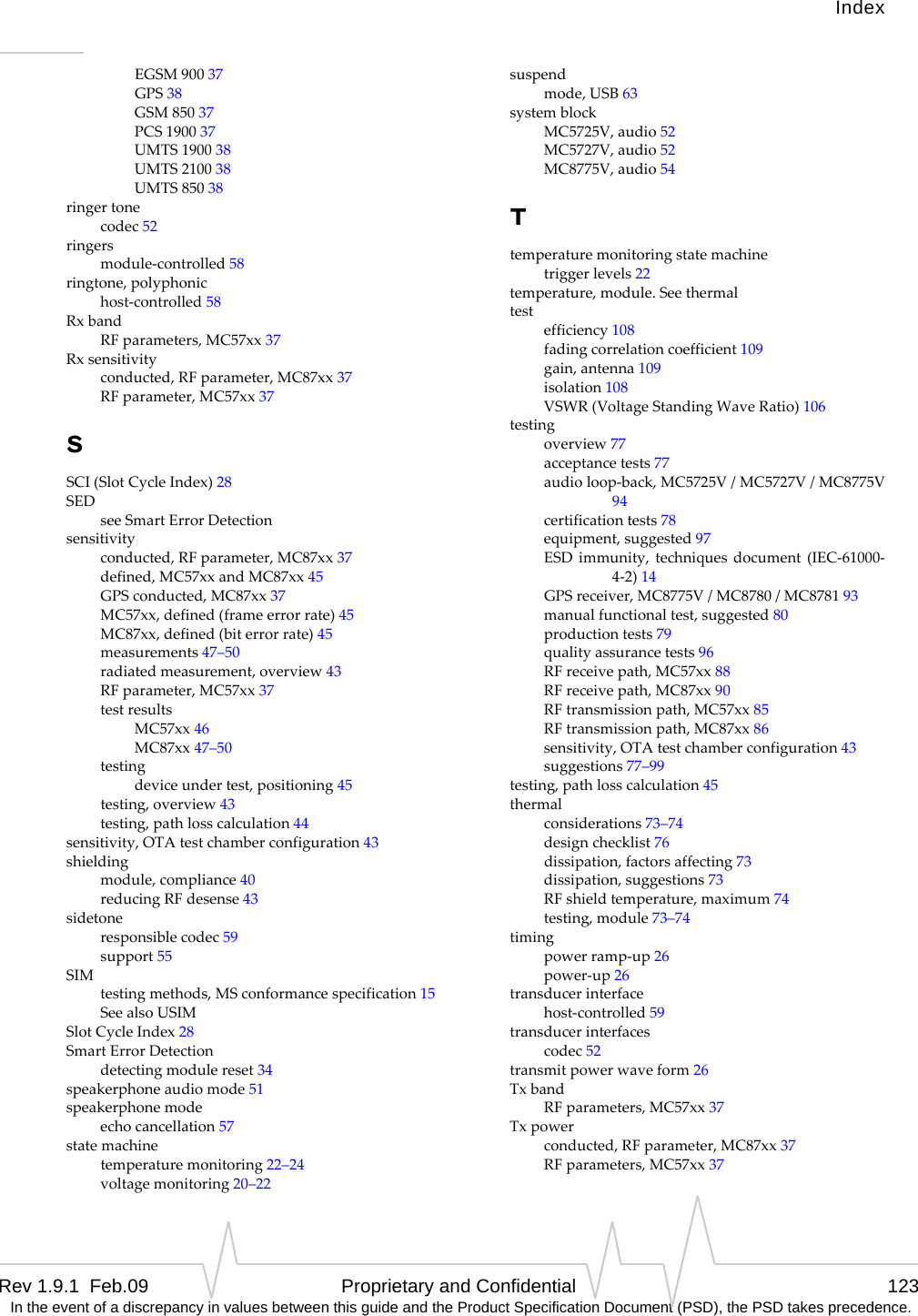
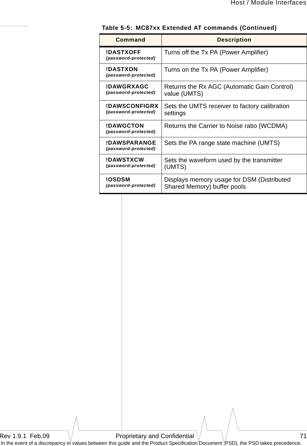
![CDMA and GSM / UMTS Mini Card Hardware Integration Guide20 Proprietary and Confidential 2130114 In the event of a discrepancy in values between this guide and the Product Specification Document (PSD), the PSD takes precedence.Forinstructionsonusingthecommands,refertoATCommandSetforUserEquipment(UE)(Release6)(+CFUN=0command),CDMACnSReference(Document2130754)(CNS_RADIO_POWER[0x1075]command),orMC87XXModemCnSReference(Document2130602)(DisableModemcommand).Voltage monitoring state machineThemodulehasastatemachinetomonitortheVCC3.3(3.0V‐3.6V)supply(Figure2‐2).Figure 2-2: Voltage monitoring state machineTable 2-1: Voltage trigger levels Condition Voltage (V)MC57xx MC8775/75VMC8780/81 MC8785VMC8790/90VMC8791V/92VVOLT_HI_CRIT 3.6 3.6 3.6VOLT_HI_NORM 3.5 3.5 3.5VOLT_LO_NORM 3.1 3.1 3.1VOLT_LO_WARN 3.0 3.0 3.05VOLT_LO_CRIT 2.9 2.9 3.00NormalLow Supply VoltageCritical(Low power mode)Low Supply VoltageWarningHigh Supply VoltageCritical(Low power mode)current_vcc > VOLT_LO_NORMcurrent_vcc < VOLT_LO_WARNcurrent_vcc > VOLT_LO_NORMHost assertsW_Disable#Host assertsW_Disable#current_vcc< VOLT_LO_CRITcurrent_vcc > VOLT_HI_CRITcurrent_vcc < VOLT_HI_NORMPower off.Handled byPower Statestate machine.](https://usermanual.wiki/Sierra-Wireless/MC5728/User-Guide-1074535-Page-20.png)
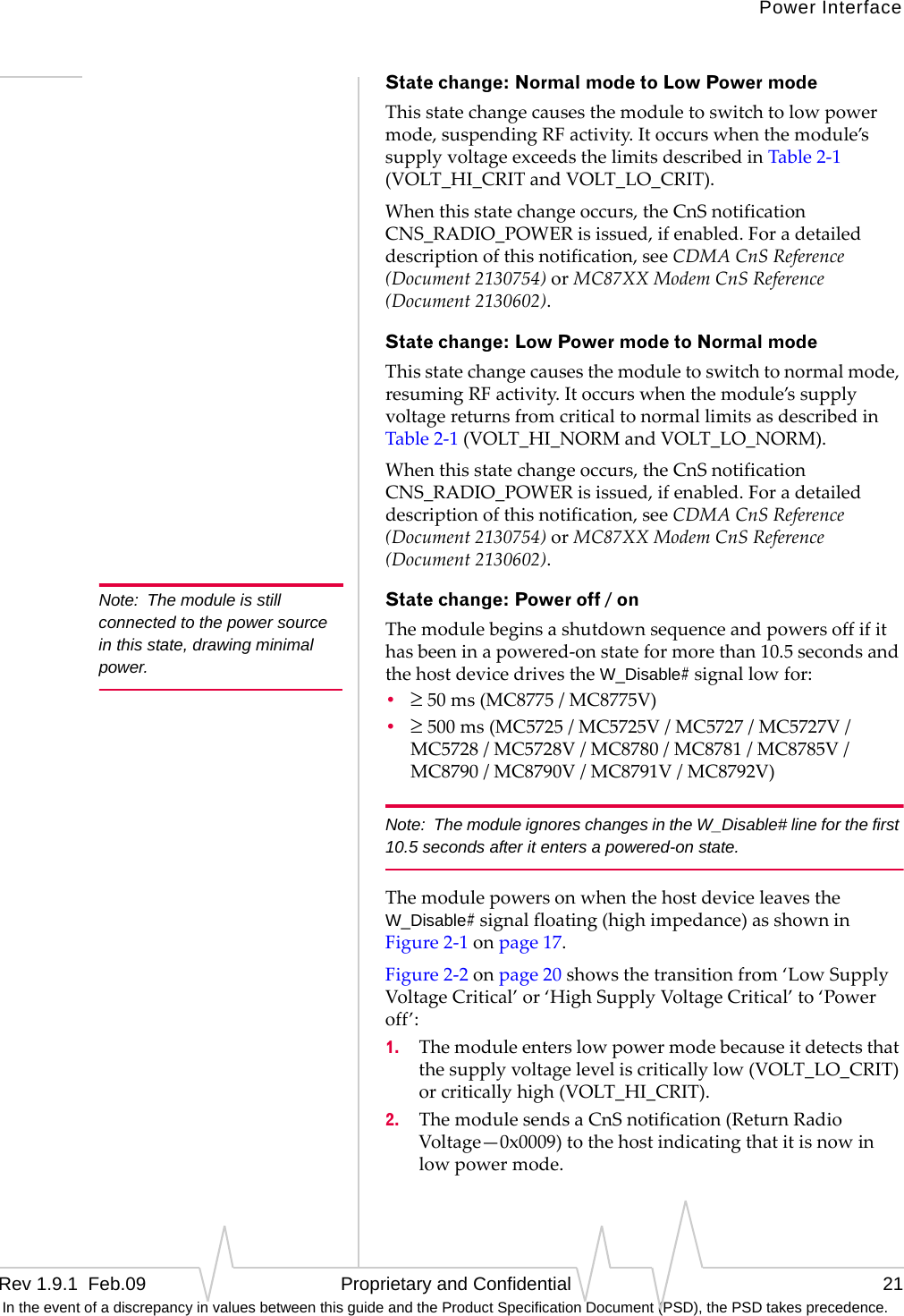
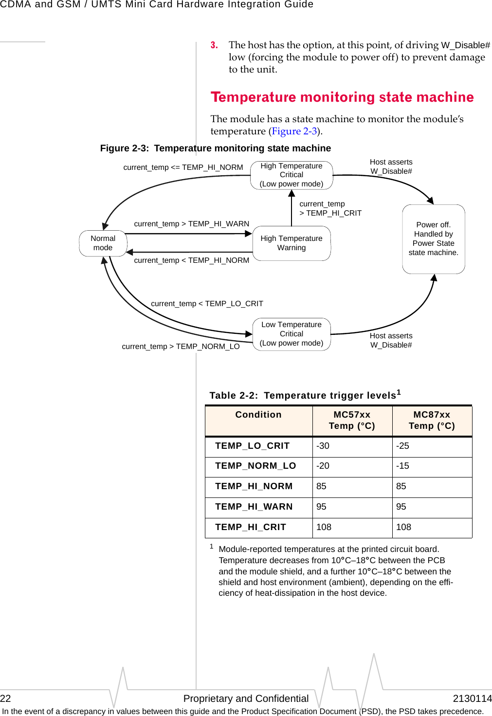
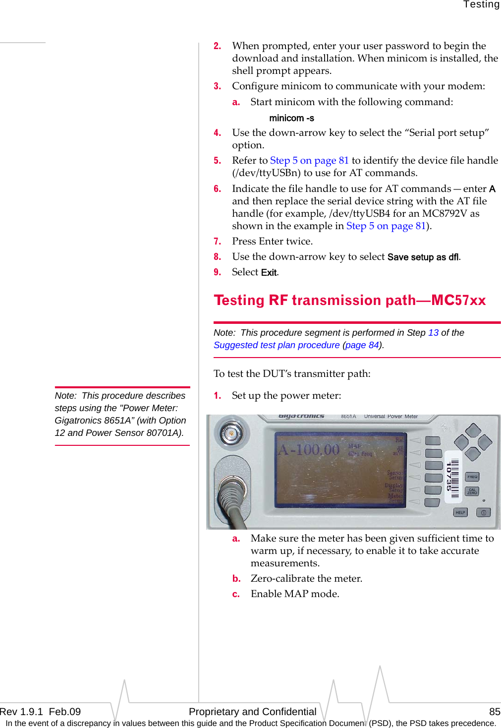
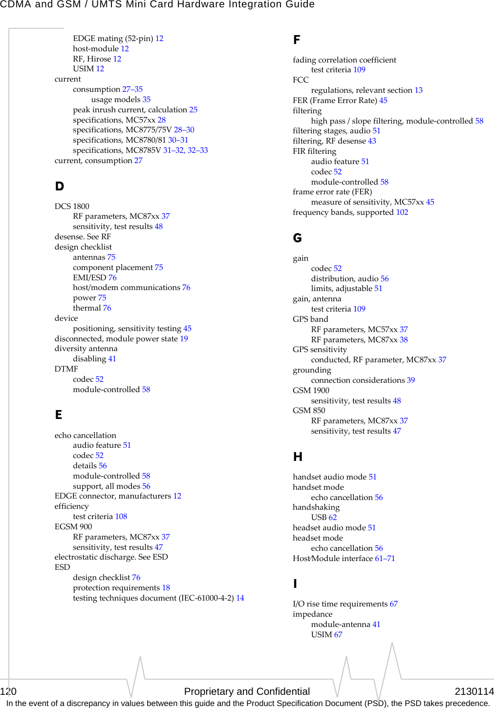
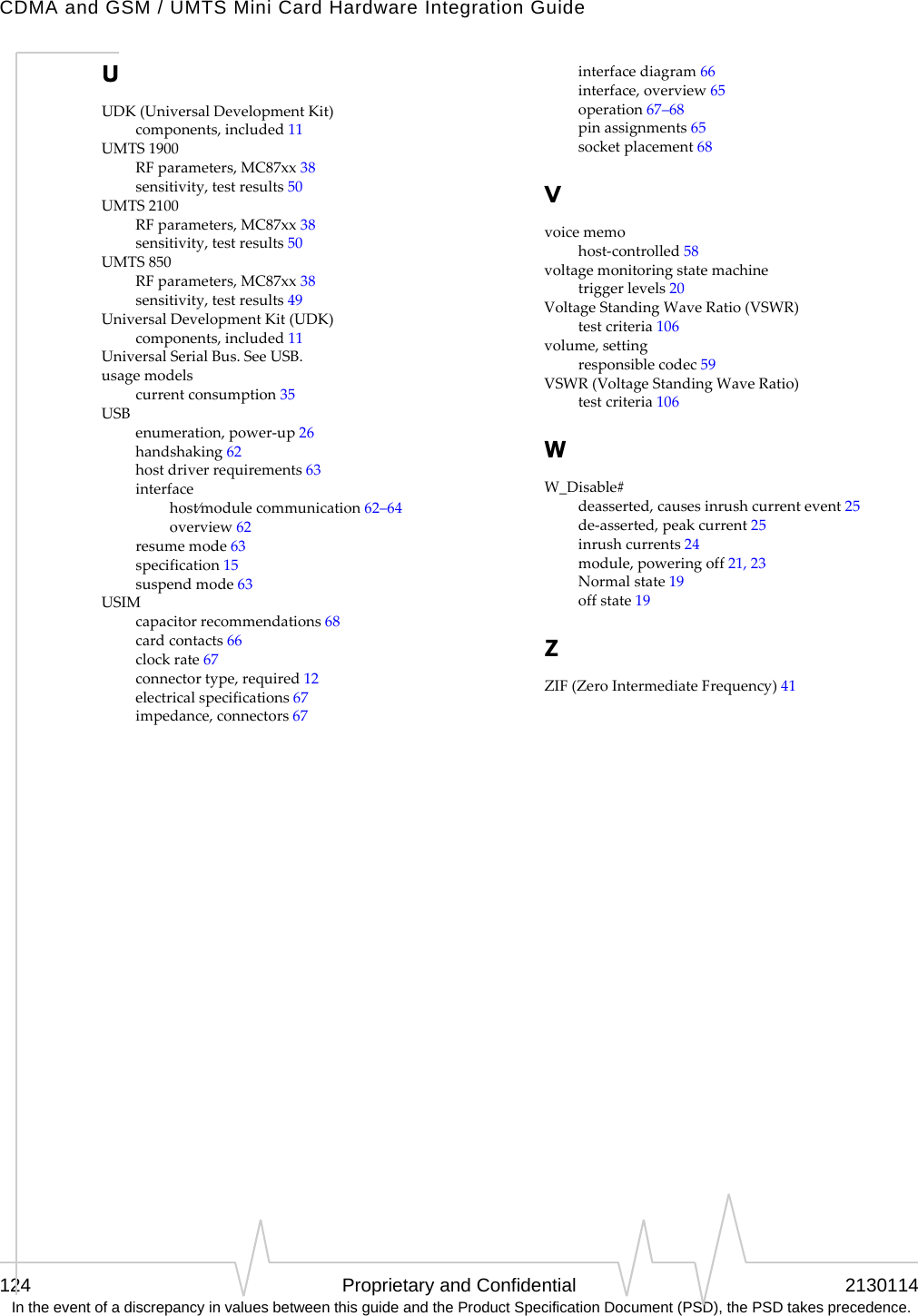
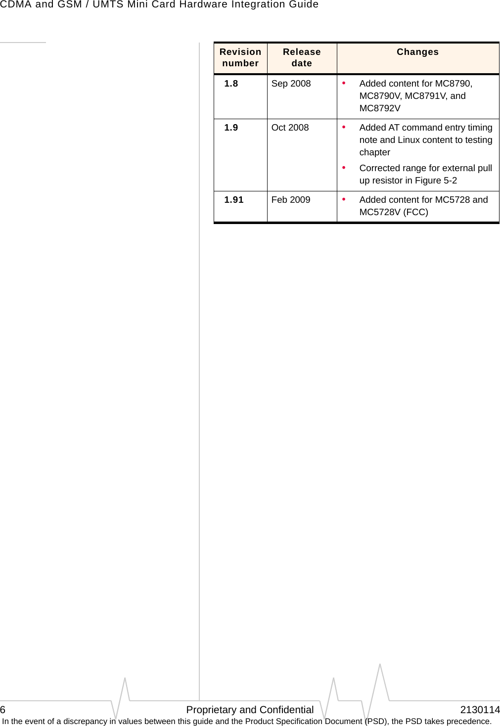
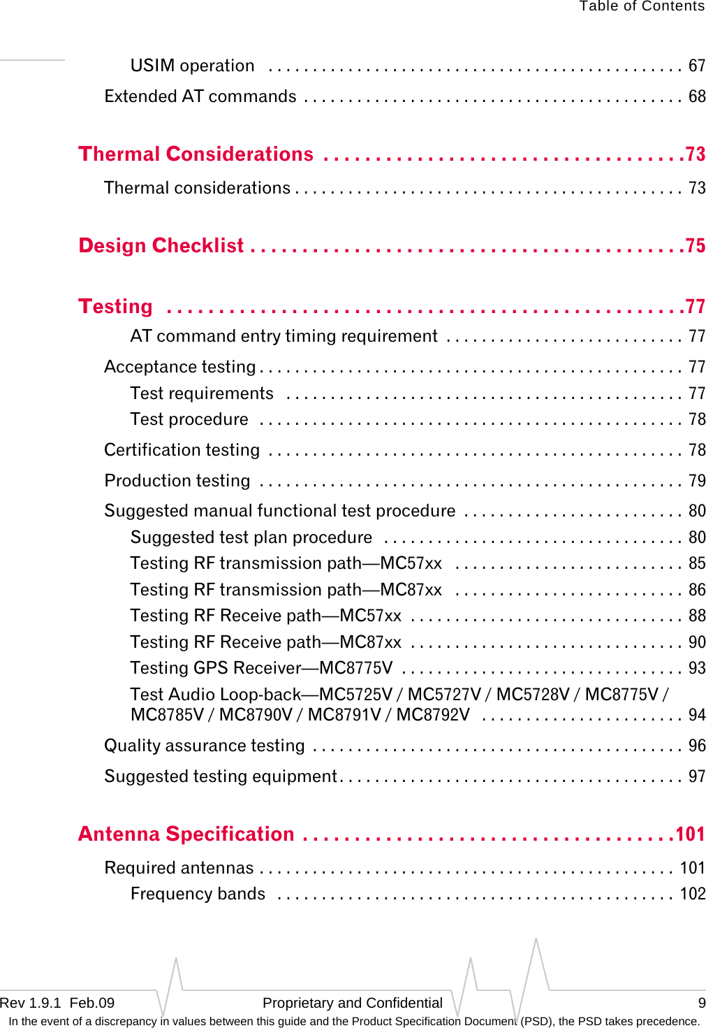
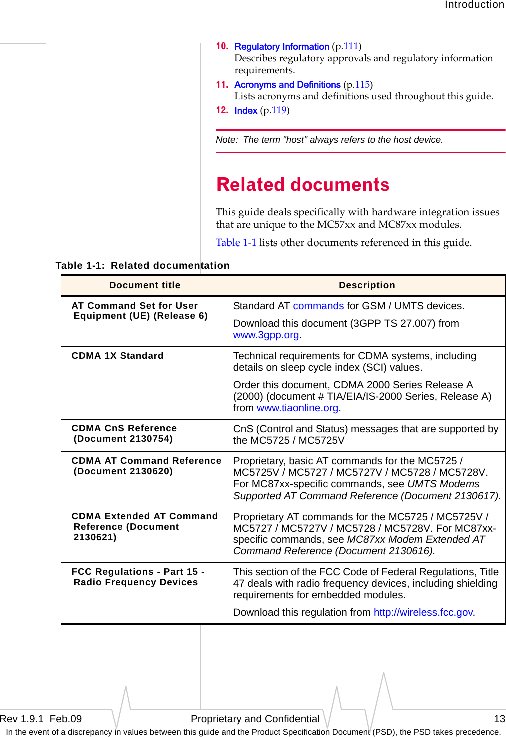
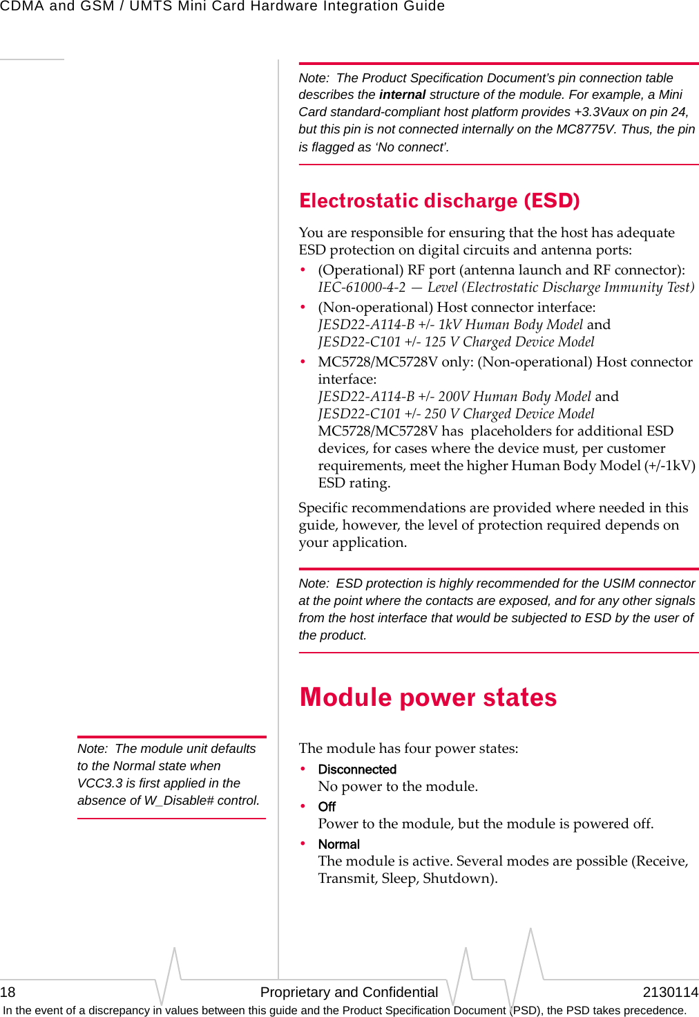
![Power InterfaceRev 1.9.1 Feb.09 Proprietary and Confidential 23 In the event of a discrepancy in values between this guide and the Product Specification Document (PSD), the PSD takes precedence.State change: Normal mode to Low Power modeThisstatechangecausesthemoduletoswitchtolowpowermode,suspendingRFactivity.ItoccurswhenthemoduletemperatureexceedsthelimitsdescribedinTable2‐2(TEMP_HI_CRITandTEMP_LO_CRIT).Whenthisstatechangeoccurs,theCnSnotificationCNS_RADIO_POWERisissued,ifenabled.Foradetaileddescriptionofthisnotification,seeCDMACnSReference(Document2130754)orMC87XXModemCnSReference(Document2130602).Aswell,theMC57xxissuestheCnSnotifi‐cationModemTooHot[0x4500]ifithastodropacallwhenshiftingtolowpowermode.State change: Low Power mode to Normal modeThisstatechangecausesthemoduletoswitchtonormalmode,resumingRFactivity.ItoccurswhenthemoduletemperaturereturnsfromcriticaltonormallimitsasdescribedinTable2‐2(TEMP_HI_NORMandTEMP_LO_NORM).Whenthisstatechangeoccurs,theCnSnotificationCNS_RADIO_POWERisissued,ifenabled.Foradetaileddescriptionofthisnotification,seeCDMACnSReference(Document2130754)orMC87XXModemCnSReference(Document2130602).State change: Power off / onThemodulebeginsashutdownsequenceandpowersoffifithasbeeninapowered‐onstateformorethan10.5secondsandthehostdevicedrivestheW_Disable#signallowfor:•≥50ms(MC8775/MC8775V)•≥500ms(MC5725/MC5725V/MC5727/MC5727V/MC5728/MC5728V/MC8780/MC8781/MC8785V/MC8790/MC8790V/MC8791V/MC8792V)Note: The module ignores changes in the W_Disable# line for the first 10.5 seconds after it enters a powered-on state.ThemodulepowersonwhenthehostdeviceleavestheW_Disable#signalfloating(highimpedance)asshowninFigure2‐1onpage17.Figure2‐3showsthetransitionfrom‘LowTemperatureCritical’or‘HighTemperatureCritical’to‘Poweroff’.1. Themoduleenterslowpowermodebecauseitdetectsthattheoperatingtemperatureiscriticallylow(TEMP_LO_CRIT)orcriticallyhigh(TEMP_HI_CRIT).](https://usermanual.wiki/Sierra-Wireless/MC5728/User-Guide-1074535-Page-23.png)


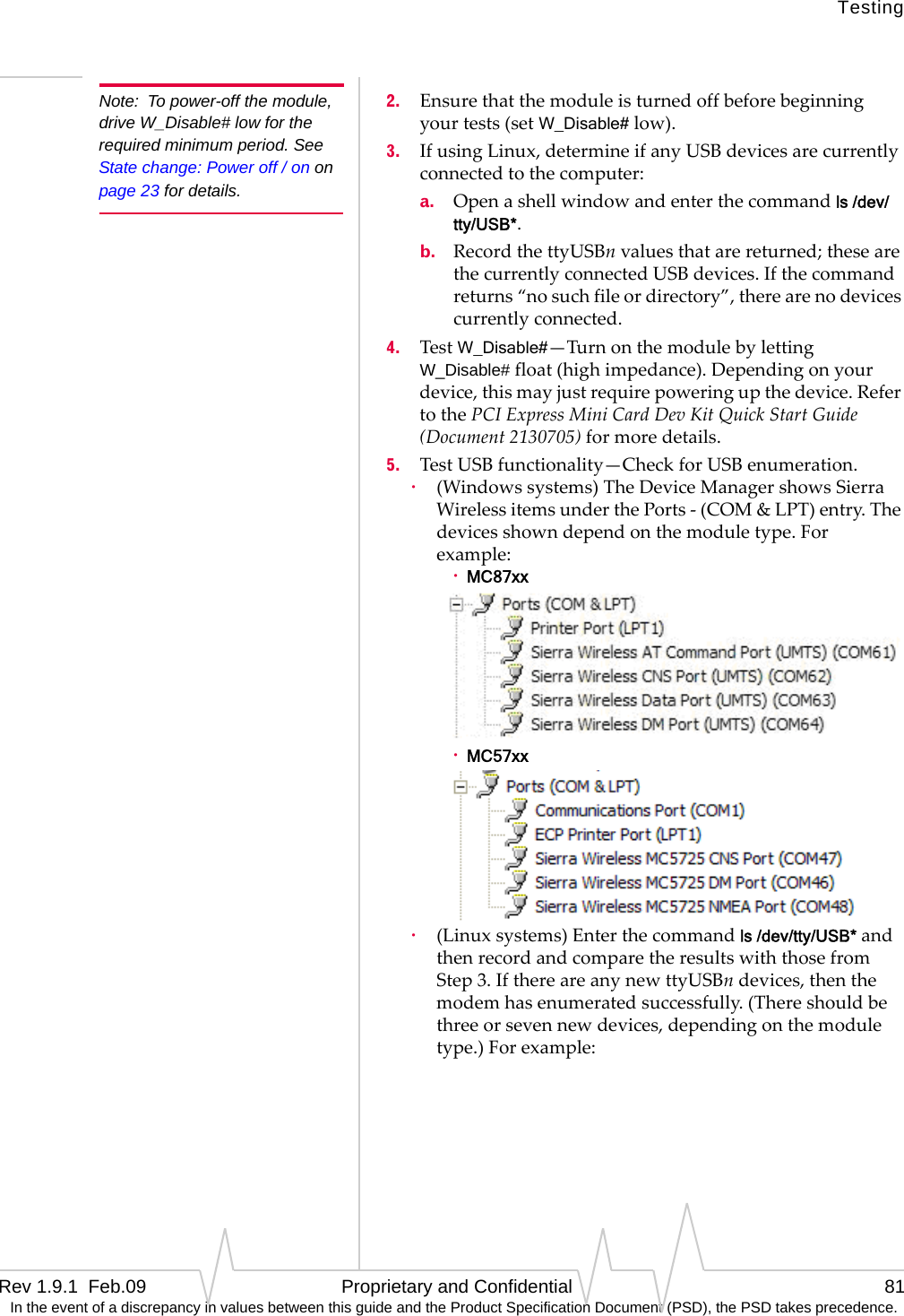
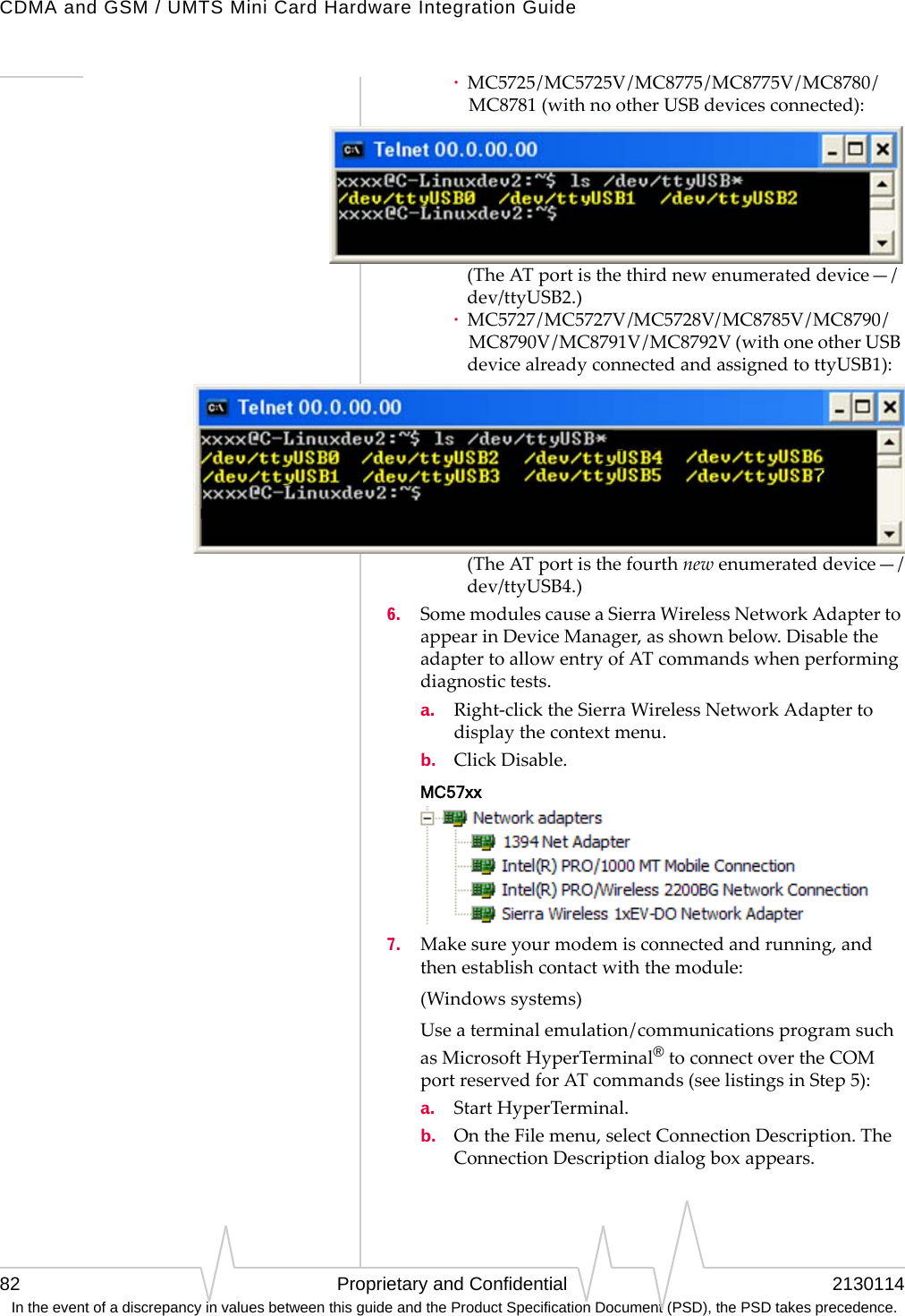
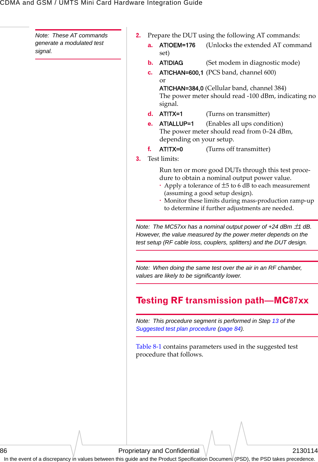
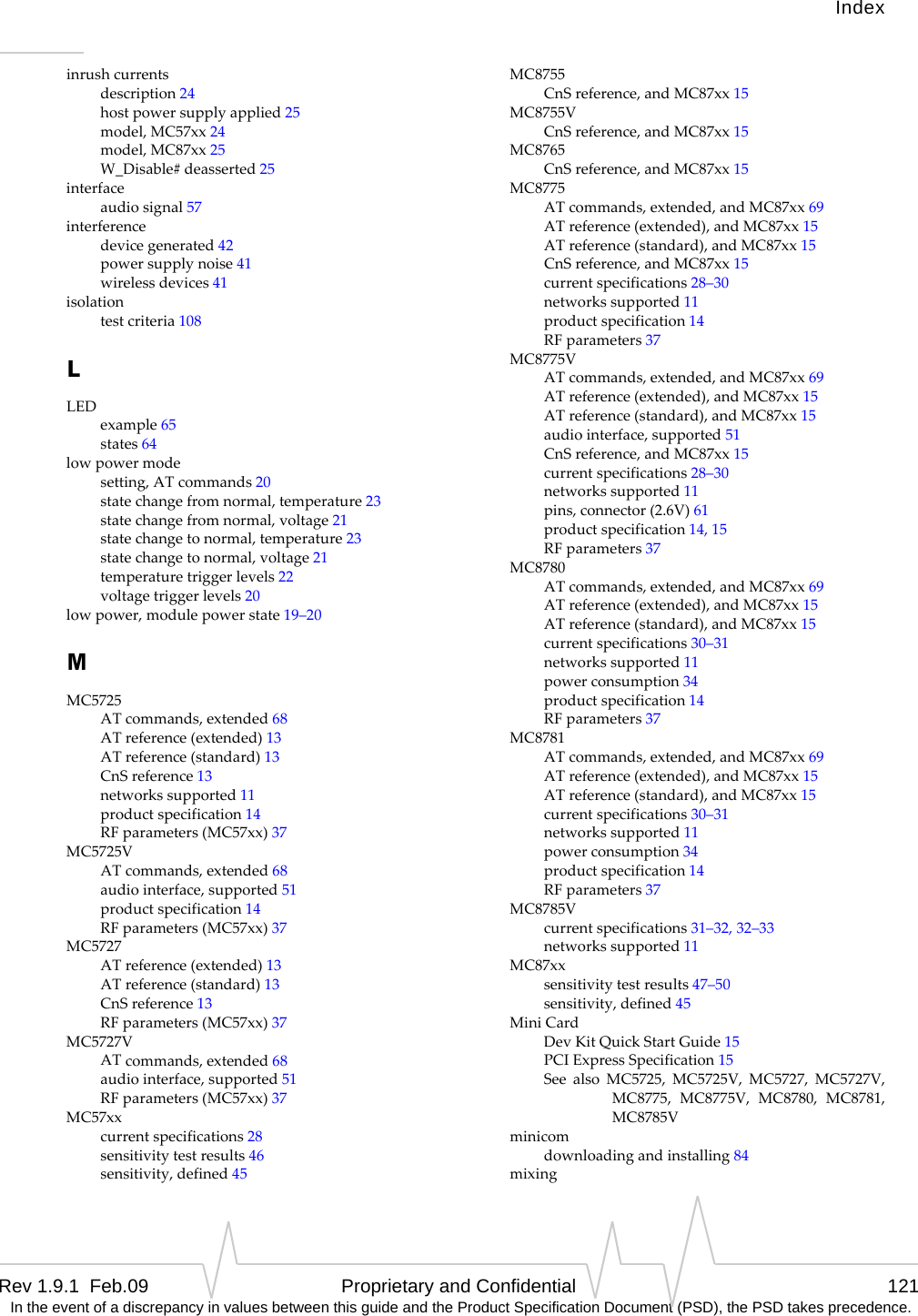
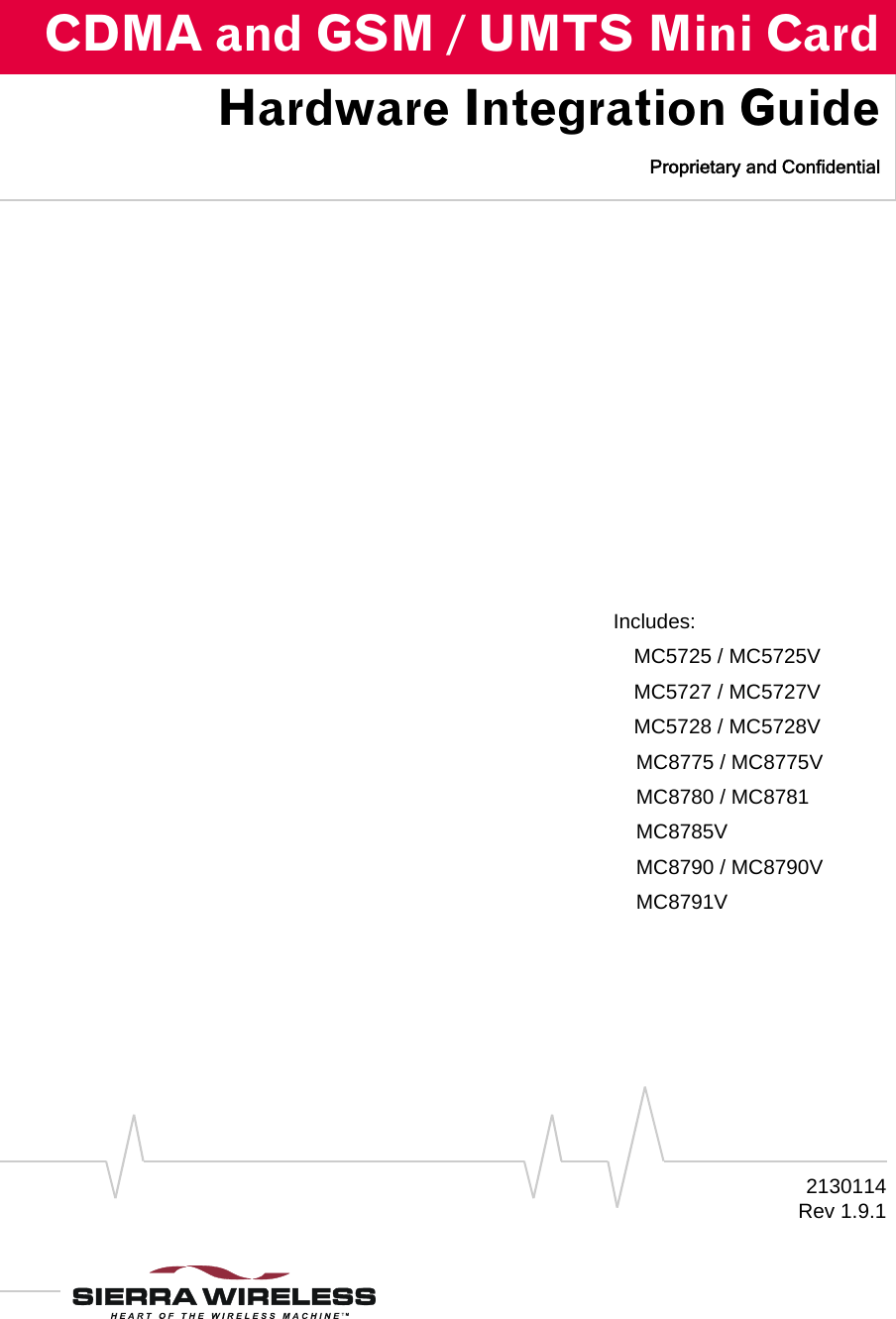
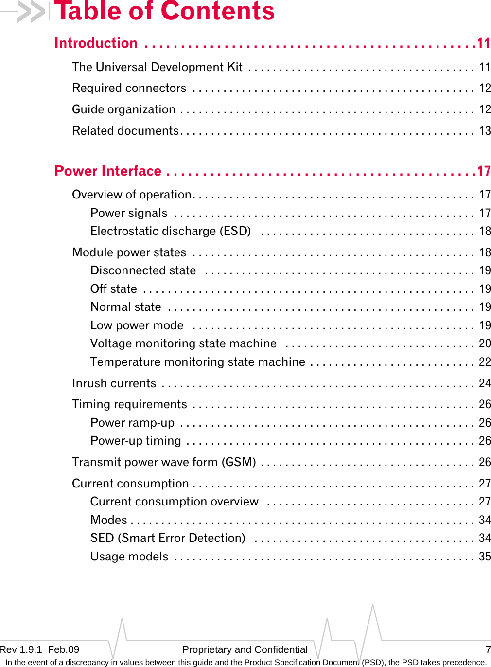
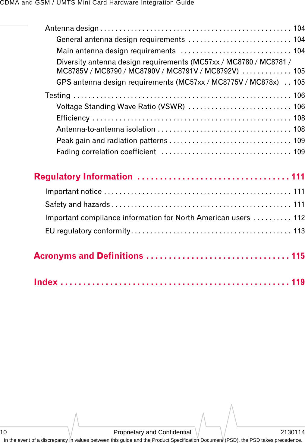
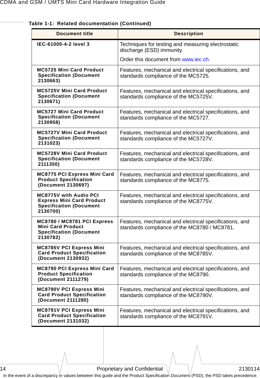
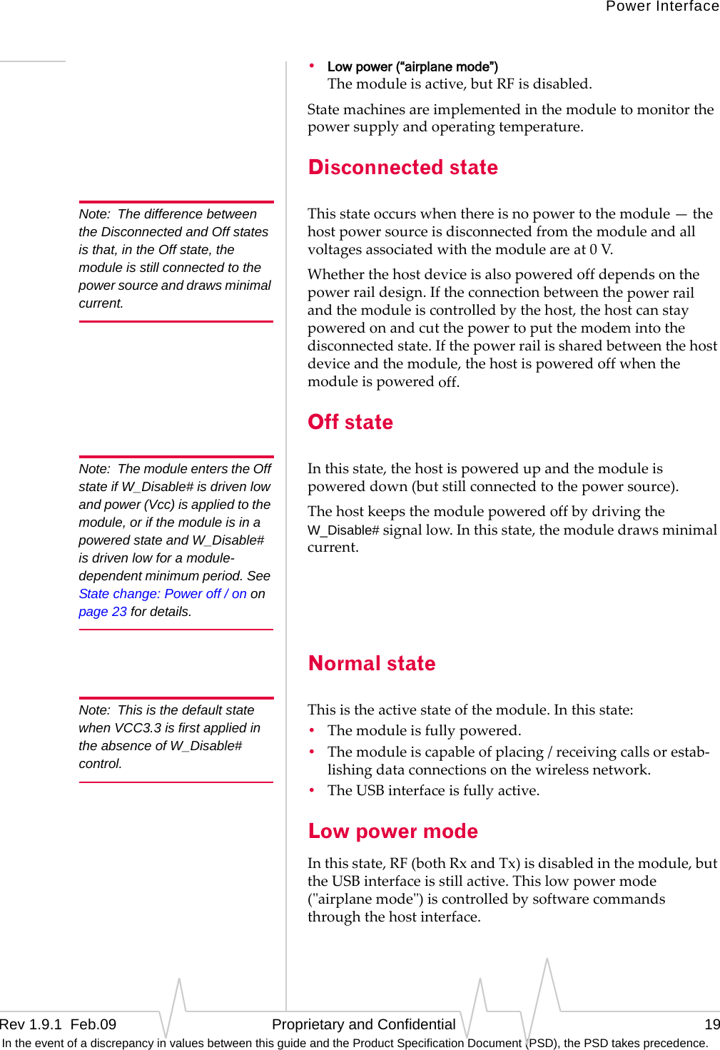
![TestingRev 1.9.1 Feb.09 Proprietary and Confidential 83 In the event of a discrepancy in values between this guide and the Product Specification Document (PSD), the PSD takes precedence.c. Type“Sierra”intheNameboxandclickOK.TheConnectTodialogboxappears.d. ClickOKwithoutchanginganyofthedisplayedinfor‐mation.TheConnectdialogboxappears.e. ClickCancel.Note: If necessary, use AT E1 to enable echo.f. TypeATZintheHyperTerminalwindow.Iftheconnectionisestablished,themessageOKappears.(Linuxsystems)Useaterminalemulation/communicationsprogramsuchasminicomtoconnectoverthedevicehandleforATcom‐mands(seelistingsinStep5):Note: If the command “minicom” is not found, then use a different program, or download minicom and repeat this step. See “Downloading and configuring minicom for Linux systems” on page 84 for details.a. Startminicom:·Firstuseofthemodem:Fromthecommandline,typeminicom‐s.‐‐alwaysshowsconfigurationmenu·Subsequentuses:Fromthecommandline,typeminicom.TheminicomconfigurationdetailsappearandthemessageOKappearswhentheconnectionisestab‐lished.8. Displaythefirmwareversionusingthiscommand:·MC57xx:AT+GMR·MC87xx:AT!GVERExampleresponse:·p2005000,0 [Aug 09, 2006 14:28:24],, VID: PID:Characters5–6arethefirmwareversion(50inthisexam‐ple).9. TesttheLED—SettheLEDinblinkingmodeusingthiscommand,thenvisuallyverifythattheLEDturnsoffandon:·MC57xx:AT!LED=0,1·MC87xx:AT!DLEDorAT!LEDCTRL10. UnlocktheextendedATcommandset,using:·MC57xx:AT!OEM=176·MC87xx:AT!ENTERCND](https://usermanual.wiki/Sierra-Wireless/MC5728/User-Guide-1074535-Page-83.png)