Sierra Wireless MC8781 850/900/1800/1900/2100 MHz Multi-band Module User Manual HW Integration Guide
Sierra Wireless Inc. 850/900/1800/1900/2100 MHz Multi-band Module HW Integration Guide
UserManual.wiki
>
Sierra Wireless
>
MC8781 User Manual
>
User Manual
Contents
1.
User Manual
2.
Updated User Manual
User Manual
Navigation menu
Upload a User Manual
Namespaces
Wiki Guide
HTML
PDF
Info
Views
User Manual
Discussion / Help
Navigation
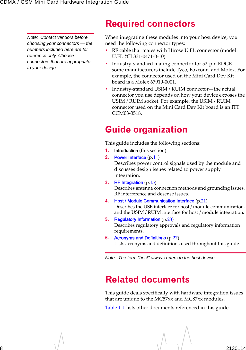
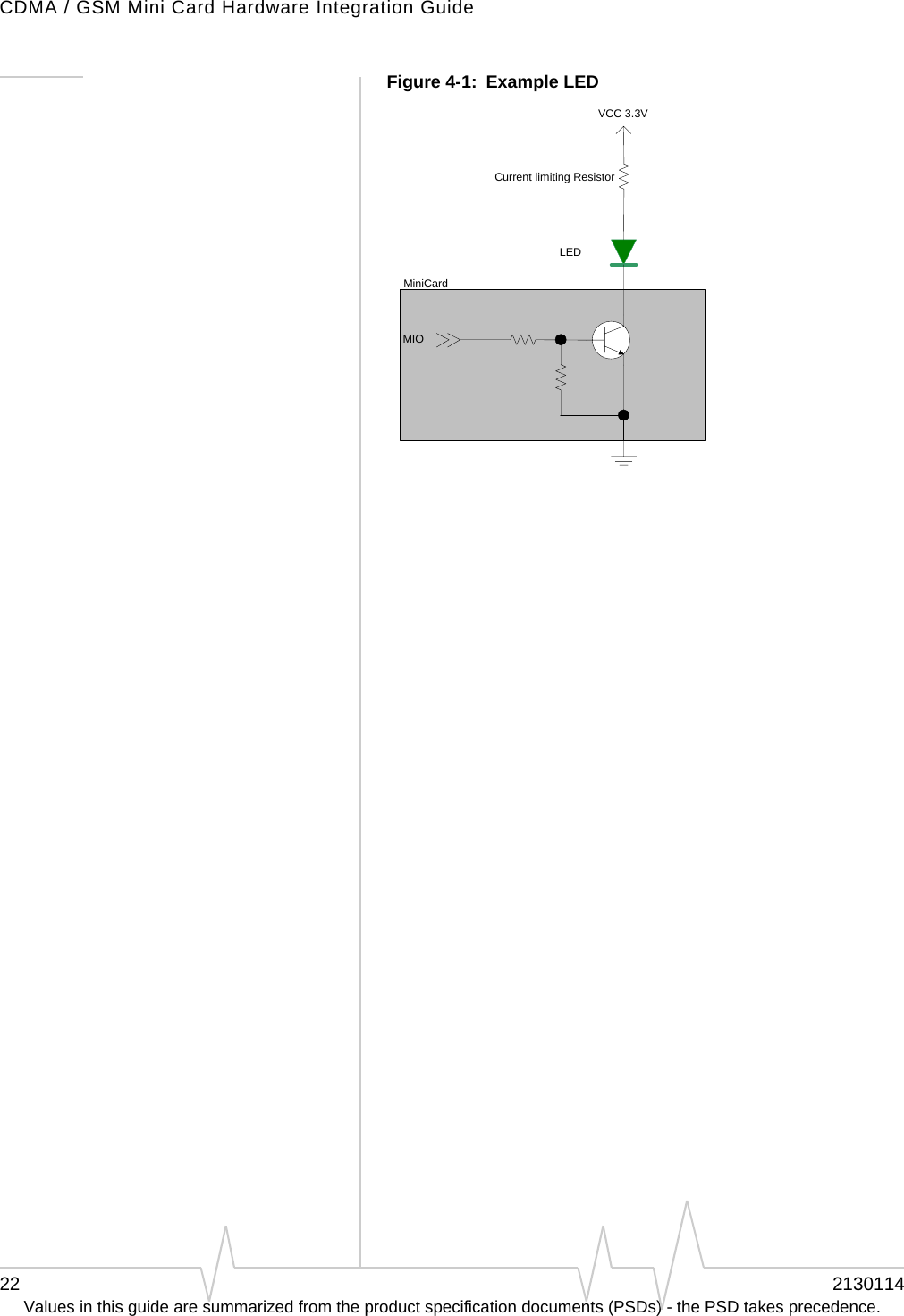
![Power InterfaceRev 1.4.1 Mar.07 13Values in this guide are summarized from the product specification documents (PSDs) - the PSD takes precedence.Normal stateNote: This is the default state when VCC3.3 is first applied in the absence of W_Disable# control.Thisistheactivestateofthemodule.Inthisstate:•Themoduleisfullypowered.•Themoduleiscapableofplacing/receivingcallsorestab‐lishingdataconnectionsonthewirelessnetwork.•TheUSBinterfaceisfullyactive.Low power modeInthisstate,RF(bothRxandTx)isdisabledinthemodule,buttheUSBinterfaceisstillactive.Thislowpowermode(ʺairplanemodeʺ)iscontrolledbysoftwarecommandsthroughthehostinterface.Forinstructionsonusingthecommands,refertoATCommandSetforUserEquipment(UE)(Release6)(+CFUN=0command),EM5625EmbeddedModule,MC5720MiniCardCnSReference(Document2130643)(CNS_RADIO_POWER[0x1075]command),orMC8755/MC8765ModemCnSReference(Document2130602)(DisableModemcommand).Usage modelsUsagemodelscanbeusedtocalculateexpectedcurrentconsumption.AsampleusagemodelisprovidedinTable2‐1.Thisexamplemodelappliestoabattery‐operateddevice.Inpractice,becausethemoduleisisolatedfromthebattery(thehostdevicemanagesthepowersource),themAhratingsdependonthedevice’ssupplyefficiency.Table 2-1: Power consumption of a sample application Used by a field worker (data only) Used for remote data loggingUpload (module Tx) 1000 kB/day 40 kB/hDownload (module Rx) 500 kB/day 100 kB/dayCoverage / data rate 1X / 80 kbps IS-95 / 14.4 kbpsHours of operation 8 / day (off 16 hrs / day) 24 / dayTotal power consumed over 24 hours60 mAh 200 mAh](https://usermanual.wiki/Sierra-Wireless/MC8781.User-Manual/User-Guide-785732-Page-15.png)