Sierra Wireless MC8781 850/900/1800/1900/2100 MHz Multi-band Module User Manual HW Integration Guide
Sierra Wireless Inc. 850/900/1800/1900/2100 MHz Multi-band Module HW Integration Guide
Contents
- 1. User Manual
- 2. Updated User Manual
User Manual
2130114
Rev 1.4.1
CDMA / GSM Mini Card
Hardware Integration Guide
Proprietary and Confidential
Includes:
MC5720 / MC5725 / MC5725V
MC8755 / MC8755V / MC8765
MC8775 / MC8775V
MC8780 / MC8781

Preface
Rev 1.4.1 Mar.07 1
Important Notice Duetothenatureofwirelesscommunications,transmission
andreceptionofdatacanneverbeguaranteed.Datamaybe
delayed,corrupted(i.e.,haveerrors)orbetotallylost.
Althoughsignificantdelaysorlossesofdataarerarewhen
wirelessdevicessuchastheSierraWirelessmodemareusedin
anormalmannerwithawell‐constructednetwork,theSierra
Wirelessmodemshouldnotbeusedinsituationswherefailure
totransmitorreceivedatacouldresultindamageofanykind
totheuseroranyotherparty,includingbutnotlimitedto
personalinjury,death,orlossofproperty.SierraWireless
acceptsnoresponsibilityfordamagesofanykindresulting
fromdelaysorerrorsindatatransmittedorreceivedusingthe
SierraWirelessmodem,orforfailureoftheSierraWireless
modemtotransmitorreceivesuchdata.
Safety and Hazards DonotoperatetheSierraWirelessmodeminareaswhere
blastingisinprogress,whereexplosiveatmospheresmaybe
present,nearmedicalequipment,nearlifesupportequipment,
oranyequipmentwhichmaybesusceptibletoanyformof
radiointerference.Insuchareas,theSierraWirelessmodem
MUSTBEPOWEREDOFF.TheSierraWirelessmodemcan
transmitsignalsthatcouldinterferewiththisequipment.
DonotoperatetheSierraWirelessmodeminanyaircraft,
whethertheaircraftisonthegroundorinflight.Inaircraft,the
SierraWirelessmodemMUSTBEPOWEREDOFF.When
operating,theSierraWirelessmodemcantransmitsignalsthat
couldinterferewithvariousonboardsystems.
Note: Some airlines may permit the use of cellular phones while the
aircraft is on the ground and the door is open. Sierra Wireless
modems may be used at this time.
Thedriveroroperatorofanyvehicleshouldnotoperatethe
SierraWirelessmodemwhileincontrolofavehicle.Doingso
willdetractfromthedriveroroperatorʹscontrolandoperation
ofthatvehicle.Insomestatesandprovinces,operatingsuch
communicationsdeviceswhileincontrolofavehicleisan
offence.
Limitation of
Liability
Theinformationinthismanualissubjecttochangewithout
noticeanddoesnotrepresentacommitmentonthepartof
SierraWireless.SIERRAWIRELESSANDITSAFFILIATES
SPECIFICALLYDISCLAIMLIABILITYFORANYANDALL
DIRECT,INDIRECT,SPECIAL,GENERAL,INCIDENTAL,
CONSEQUENTIAL,PUNITIVEOREXEMPLARYDAMAGES
INCLUDING,BUTNOTLIMITEDTO,LOSSOFPROFITSOR
CDMA / GSM Mini Card Hardware Integration Guide
22130114
REVENUEORANTICIPATEDPROFITSORREVENUE
ARISINGOUTOFTHEUSEORINABILITYTOUSEANY
SIERRAWIRELESSPRODUCT,EVENIFSIERRAWIRELESS
AND/ORITSAFFILIATESHASBEENADVISEDOFTHE
POSSIBILITYOFSUCHDAMAGESORTHEYARE
FORESEEABLEORFORCLAIMSBYANYTHIRDPARTY.
Notwithstandingtheforegoing,innoeventshallSierra
Wirelessand/oritsaffiliatesaggregateliabilityarisingunderor
inconnectionwiththeSierraWirelessproduct,regardlessof
thenumberofevents,occurrences,orclaimsgivingriseto
liability,beinexcessofthepricepaidbythepurchaserforthe
SierraWirelessproduct.
Patents Portionsofthisproductmaybecoveredbysomeorallofthe
followingUSpatents:
5,515,013 5,629,960 5,845,216 5,847,553 5,878,234
5,890,057 5,929,815 6,169,884 6,191,741 6,199,168
6,339,405 6,359,591 6,400,336 6,516,204 6,561,851
6,643,501 6,653,979 6,697,030 6,785,830 6,845,249
6,847,830 6,876,697 6,879,585 6,886,049 6,968,171
6,985,757 7,023,878 7,053,843 7,106,569 D442,170
D459,303
andotherpatentspending.
Thisproductincludes
technologylicensedfrom:
LicensedbyQUALCOMMIncorporatedunderoneormoreof
thefollowingUnitedStatespatentsand/ortheircounterparts
inothernations:
4,901,307 5,056,109 5,101,501 5,109,390 5,228,054
5,267,261 5,267,262 5,337,338 5,414,796 5,416,797
5,490,165 5,504,773 5,506,865 5,511,073 5,535,239
5,544,196 5,568,483 5,600,754 5,657,420 5,659,569
5,710,784 5,778,338
ManufacturedorsoldbySierraWirelessoritslicenseesunder
oneormorepatentslicensedfromInterDigitalGroup.
Copyright ©2007SierraWireless.Allrightsreserved.
Trademarks AirCardand“HeartoftheWirelessMachine”areregistered
trademarksofSierraWireless.
SierraWireless,theSierraWirelesslogo,theredwavedesign,
thered‐tippedantenna,andWatcheraretrademarksofSierra
Wireless.
Windows®isaregisteredtrademarkofMicrosoftCorporation.
Preface
Rev 1.4.1 Mar.07 3
QUALCOMM®isaregisteredtrademarkofQUALCOMM
Incorporated.Usedunderlicense.
Othertrademarksarethepropertyoftherespectiveowners.
Contact
Information
Consultourwebsiteforup‐to‐dateproductdescriptions,
documentation,applicationnotes,firmwareupgrades,trouble‐
shootingtips,andpressreleases:
www.sierrawireless.com
Sales Desk: Phone: 1-604-232-1488
Hours: 8:00 AM to 5:00 PM Pacific Time
E-mail: sales@sierrawireless.com
Post: Sierra Wireless
13811 Wireless Way
Richmond, BC
Canada V6V 3A4
Fax: 1-604-231-1109
Web: www.sierrawireless.com

CDMA / GSM Mini Card Hardware Integration Guide
42130114

Rev 1.4.1 Mar.07 5
Table of Contents
Introduction . . . . . . . . . . . . . . . . . . . . . . . . . . . . . . . . . . . . . . . . . . . . . . .7
The Universal Development Kit . . . . . . . . . . . . . . . . . . . . . . . . . . . . . . . . . . . . . . 7
Required connectors . . . . . . . . . . . . . . . . . . . . . . . . . . . . . . . . . . . . . . . . . . . . . . . 8
Guide organization . . . . . . . . . . . . . . . . . . . . . . . . . . . . . . . . . . . . . . . . . . . . . . . . . 8
Related documents. . . . . . . . . . . . . . . . . . . . . . . . . . . . . . . . . . . . . . . . . . . . . . . . . 8
Power Interface . . . . . . . . . . . . . . . . . . . . . . . . . . . . . . . . . . . . . . . . . . .11
Overview of operation. . . . . . . . . . . . . . . . . . . . . . . . . . . . . . . . . . . . . . . . . . . . . . 11
Power signals . . . . . . . . . . . . . . . . . . . . . . . . . . . . . . . . . . . . . . . . . . . . . . . . . 11
Electrostatic discharge (ESD) . . . . . . . . . . . . . . . . . . . . . . . . . . . . . . . . . . . 11
Module power states . . . . . . . . . . . . . . . . . . . . . . . . . . . . . . . . . . . . . . . . . . . . . . 12
Disconnected state . . . . . . . . . . . . . . . . . . . . . . . . . . . . . . . . . . . . . . . . . . . . 12
Off state . . . . . . . . . . . . . . . . . . . . . . . . . . . . . . . . . . . . . . . . . . . . . . . . . . . . . . 12
Normal state . . . . . . . . . . . . . . . . . . . . . . . . . . . . . . . . . . . . . . . . . . . . . . . . . . 13
Low power mode . . . . . . . . . . . . . . . . . . . . . . . . . . . . . . . . . . . . . . . . . . . . . . 13
Usage models . . . . . . . . . . . . . . . . . . . . . . . . . . . . . . . . . . . . . . . . . . . . . . . . . 13
RF Integration . . . . . . . . . . . . . . . . . . . . . . . . . . . . . . . . . . . . . . . . . . . .15
RF connection . . . . . . . . . . . . . . . . . . . . . . . . . . . . . . . . . . . . . . . . . . . . . . . . . . . . 15
Ground connection . . . . . . . . . . . . . . . . . . . . . . . . . . . . . . . . . . . . . . . . . . . . . . . . 16
Shielding . . . . . . . . . . . . . . . . . . . . . . . . . . . . . . . . . . . . . . . . . . . . . . . . . . . . . 16
Antenna and cabling . . . . . . . . . . . . . . . . . . . . . . . . . . . . . . . . . . . . . . . . . . . 17
Interference and sensitivity . . . . . . . . . . . . . . . . . . . . . . . . . . . . . . . . . . . . . . . . . 18
Power supply noise . . . . . . . . . . . . . . . . . . . . . . . . . . . . . . . . . . . . . . . . . . . . 18
Interference from other wireless devices . . . . . . . . . . . . . . . . . . . . . . . . . . 18
Device-generated RF . . . . . . . . . . . . . . . . . . . . . . . . . . . . . . . . . . . . . . . . . . . 19
Host / Module Communication Interface . . . . . . . . . . . . . . . . . . . .21

CDMA / GSM Mini Card Hardware Integration Guide
62130114
LED output . . . . . . . . . . . . . . . . . . . . . . . . . . . . . . . . . . . . . . . . . . . . . . . . . . . 21
Regulatory Information . . . . . . . . . . . . . . . . . . . . . . . . . . . . . . . . . . . 23
Important notice . . . . . . . . . . . . . . . . . . . . . . . . . . . . . . . . . . . . . . . . . . . . . . . . . . 23
Safety and hazards . . . . . . . . . . . . . . . . . . . . . . . . . . . . . . . . . . . . . . . . . . . . . . . . 23
Important compliance information for North American users . . . . . . . . . . . 24
Acronyms and Definitions . . . . . . . . . . . . . . . . . . . . . . . . . . . . . . . . . 27
Index . . . . . . . . . . . . . . . . . . . . . . . . . . . . . . . . . . . . . . . . . . . . . . . . . . . . 31

1
Rev 1.4.1 Mar.07 7
1: Introduction
SierraWireless’MiniCardmodulesformtheradiocomponent
fortheproductsinwhichtheyareembedded.MiniCardsare
availableforuseonCDMAandGSMnetworks,including:
Note: Throughout this
document, MC57xx and MC87xx
refer to the entire suites of
CDMA and GSM Mini Cards
respectively.
•MC5720andMC5725—operateonCDMAnetworksusing
theIS‐95AandCDMA1X,and1xEV‐DO(IS‐856)network
standards
•MC8755 / MC8755V,MC8765,MC8775 / MC8775V,and
MC8780 / MC8781—operateonGSMnetworksusingthe
GSM/GPRS/EDGE/UMTS/HSDPAnetworkstandards
Purpose of this guide
ThisguideaddressesissuesthataffecttheintegrationofSierra
Wirelessmodulesintohostproducts,andincludesdesign
recommendationsforthehostproducts.
Note: An understanding of network technology and experience in
integrating hardware components into electronic equipment is
assumed.
The Universal Development Kit
SierraWirelessmanufacturesaUniversalDevelopmentKit
(UDK)thatfacilitatesallphasesoftheintegrationprocess.
Thiskitisahardwaredevelopmentplatformthatisdesigned
tosupportmultiplemembersoftheWirelessEmbedded
Moduleproductfamily.Itcontainsthehardwarecomponents
thataretypicallynecessaryforevaluatinganddevelopingwith
themodule,including:
•Developmentboard
•Cables
•Antennas
•Otheraccessories

CDMA / GSM Mini Card Hardware Integration Guide
82130114
Required connectors
Note: Contact vendors before
choosing your connectors — the
numbers included here are for
reference only. Choose
connectors that are appropriate
to your design.
Whenintegratingthesemodulesintoyourhostdevice,you
needthefollowingconnectortypes:
•RFcablethatmateswithHiroseU.FLconnector(model
U.FL#CL331‐0471‐0‐10)
•Industry‐standardmatingconnectorfor52‐pinEDGE—
somemanufacturersincludeTyco,Foxconn,andMolex.For
example,theconnectorusedontheMiniCardDevKit
boardisaMolex67910‐0001.
•Industry‐standardUSIM/RUIMconnector—theactual
connectoryouusedependsonhowyourdeviceexposesthe
USIM/RUIMsocket.Forexample,theUSIM/RUIM
connectorusedontheMiniCardDevKitboardisanITT
CCM03‐3518.
Guide organization
Thisguideincludesthefollowingsections:
1. Introduction(thissection)
2. Power Interface(p.11)
Describespowercontrolsignalsusedbythemoduleand
discussesdesignissuesrelatedtopowersupply
integration.
3. RF Integration(p.15)
Describesantennaconnectionmethodsandgroundingissues,
RFinterferenceanddesenseissues.
4. Host / Module Communication Interface(p.21)
DescribestheUSBinterfaceforhost/modulecommunication,
andtheUSIM/RUIMinterfaceforhost/moduleintegration.
5. Regulatory Information(p.23)
Describesregulatoryapprovalsandregulatoryinformation
requirements.
6. Acronyms and Definitions(p.27)
Listsacronymsanddefinitionsusedthroughoutthisguide.
Note: The term "host" always refers to the host device.
Related documents
Thisguidedealsspecificallywithhardwareintegrationissues
thatareuniquetotheMC57xxandMC87xxmodules.
Table1‐1listsotherdocumentsreferencedinthisguide.

Introduction
Rev 1.4.1 Mar.07 9
Table 1-1: Related documentation
Document title Description
AT Command Set for User
Equipment (UE) (Release 6) This 3GPP technical specification describes standard AT
commands for GSM / UMTS devices.
Download this document (3GPP TS 27.007) from
www.3gpp.org.
CDMA 1X Standard Technical requirements for CDMA systems, including
details on sleep cycle index (SCI) values.
Order this document, CDMA 2000 Series Release A
(2000) (document # TIA/EIA/IS-2000 Series, Release A)
from www.tiaonline.org.
EM5625 Embedded Module,
MC5720 MiniCard CnS
Reference (Document
2130643)
CnS (Control and Status) messages that are supported by
the MC5720 and the MC5725.
EM5625 Embedded Module,
MC5720 MiniCard AT
Command Reference
(Document 2130620)
Proprietary, basic AT commands for the MC5720 / 5725 /
5725V. For MC87xx-specific commands, see UMTS
Modems Supported AT Command Reference (Document
2130617).
EM5625 Embedded Module,
MC5720 MiniCard Extended AT
Command Reference
(Document 2130621)
Proprietary AT commands for the MC5720 / 5725 / 5725V.
For MC87xx-specific commands, see MC87xx Modem
Extended AT Command Reference (Document 2130616).
FCC Regulations - Part 15 -
Radio Frequency Devices This section of the FCC Code of Federal Regulations, Title
47 deals with radio frequency devices, including shielding
requirements for embedded modules.
Download this regulation from http://wireless.fcc.gov.
IEC-61000-4-2 level 3 Techniques for testing and measuring electrostatic
discharge (ESD) immunity.
Order this document from www.iec.ch.
MC5720 MiniCard Product
Specification (Document
2130599)
Features, mechanical and electrical specifications, and
standards compliance of the MC5720.
MC5725 Mini Card Product
Specification (Document
2130663)
Features, mechanical and electrical specifications, and
standards compliance of the MC5725.
MC5725V Mini Card Product
Specification (Document
2130671)
Features, mechanical and electrical specifications, and
standards compliance of the MC5725V.
MC8755 / MC8765 PCI Express
Mini Card Product
Specification (Document
2130637)
Features, mechanical and electrical specifications, and
standards compliance of the MC8755 / MC8765.
CDMA / GSM Mini Card Hardware Integration Guide
10 2130114
MC8755V with Audio PCI
Express Mini Card Product
Specification (Document
2130664)
Features, mechanical and electrical specifications, and
standards compliance of the MC8755V.
MC8775 PCI Express Mini Card
Product Specification
(Document 2130697)
Features, mechanical and electrical specifications, and
standards compliance of the MC8775.
MC8775V with Audio PCI
Express Mini Card Product
Specification (Document
2130700)
Features, mechanical and electrical specifications, and
standards compliance of the MC8775V.
MC8780/MC8781 PCI Express
Mini Card Product
Specification (Document
2130782)
Features, mechanical and electrical specifications, and
standards compliance of the MC8780 / MC8781.
MC8755/MC8765 Modem CnS
Reference (Document
2130602)
This document describes the CnS (Control and Status)
messages supported by the MC8755 / MC8755V /
MC8765 / MC8775 / MC8775V / MC8780 / MC8781.
MC87xx Modem Extended AT
Command Reference
(Document 2130616)
Proprietary AT commands for the MC87xx. For MC57xx-
specific commands, see the EM5625 Embedded Module,
MC5720 MiniCard Extended AT Command Reference
(Document 2130621).
Mobile Station (MS)
Conformance Specification;
Part 4: Subscriber Interface
Module
This 3GPP technical specification describes SIM testing
methods.
Download this document (3GPP TS 11.10-4) from
www.3gpp.org.
PCI Express Mini Card Dev Kit
Quick Start Guide (Document
2130705)
This document describes the setup and configuration of
modules.
PCI Express Mini Card
Electromechanical
Specification Revision 1.1
Download this document from www.pcisig.com.
UMTS Modems Supported AT
Command Reference
(Document 2130617)
This document describes proprietary, basic AT commands
for the MC87xx. For MC57xx-specific commands, see the
EM5625 Embedded Module, MC5720 Mini-Card AT
Command Reference (Document 2130620).
Universal Serial Bus
Specification, Rev 2.0 Download this specification from www.usb.org.
Table 1-1: Related documentation (Continued)
Document title Description

2
Rev 1.4.1 Mar.07 11
Values in this guide are summarized from the product specification documents (PSDs) - the PSD takes precedence.
2: Power Interface
Overview of operation
Note: This chapter contains information for both the CDMA (MC57xx)
and GSM (MC87xx) modules.
Information that is unique to specific module types is clearly
identified.
Themoduleisdesignedtousea3.3V(nominal)powersupply,
providedbythehost.Itisthehost’sresponsibilitytoprovide
safeandcontinuouspowertothemoduleatalltimes;the
moduledoesNOThaveanindependentpowersupply,or
protectioncircuitstoguardagainstelectricalissues.
Themodule’spowerstateiscontrolledbythehost’sassertion/
de‐assertionoftheW_Disable#signal.Themodulealso
monitorsitssupplyvoltageandrequestsshutdownifthe
supplyisinsufficient.
Power signals
Themodulemustbeconnectedtoa3.3Vpowersupply(as
describedinPCIExpressMiniCardElectromechanicalSpecifi‐
cationRevision1.1).
TheMC87xxhasmorepowerpinsthantheMC57xxdueto
higherpeakcurrentrequirementsforGSMdevices.
Fordetailedpinoutandvoltage/currentrequirementsofthese
modules,seetheProductSpecificationDocumentforyour
MiniCard.
Electrostatic discharge (ESD)
Youareresponsibleforensuringthatthehosthasadequate
ESDprotectionondigitalcircuitsandantennaports:
•(Operational)RFport(antennalaunchandRFconnector):
IEC‐61000‐4‐2—Level(ElectrostaticDischargeImmunityTest)
•(Non‐operational)Hostconnectorinterface:
JESD22‐A114‐B+/‐1kVHumanBodyModeland
JESD22‐C101+/‐125VChargedDeviceModel
Specificrecommendationsareprovidedwhereneededinthis
guide,however,thelevelofprotectionrequireddependson
yourapplication.

CDMA / GSM Mini Card Hardware Integration Guide
12 2130114
Values in this guide are summarized from the product specification documents (PSDs) - the PSD takes precedence.
Note: ESD protection is highly recommended for the USIM / RUIM
connector at the point where the contacts are exposed, and for any
other signals from the host interface that would be subjected to ESD
by the user of the product.
Module power states
Note: The module unit defaults
to the Normal state when
VCC3.3 is first applied in the
absence of W_Disable# control.
Themodulehasfourpowerstates:
•Disconnected
Nopowertothemodule.
•Off
Powertothemodule,butthemoduleispoweredoff.
•Normal
Themoduleisactive.Severalmodesarepossible(Receive,
Transmit,Sleep,Shutdown).
•Low power (“airplane mode”)
Themoduleisactive,butRFisdisabled.
Statemachinesareimplementedinthemoduletomonitorthe
powersupplyandoperatingtemperature.
Disconnected state
Note: The difference between
the Disconnected and Off states
is that in the Off state, the
module is still connected to the
power source and draws minimal
current.
Thisstateoccurswhenthereisnopowertothemodule—the
hostpowersourceisdisconnectedfromthemoduleandall
voltagesassociatedwiththemoduleareat0V.
Whetherthehostdeviceisalsopoweredoffdependsonthe
powerraildesign.Iftheconnectionbetweenthepowerrail
andthemoduleiscontrolledbythehost,thehostcanstay
poweredonandcutthepowertoputthemodemintothe
disconnectedstate.Ifthepowerrailissharedbetweenthehost
deviceandthemodule,thehostispoweredoffwhenthe
moduleispoweredoff.
Off state
Inthisstate,thehostispoweredupandthemoduleis
powereddown(butstillconnectedtothepowersource).
Thehostkeepsthemodulepoweredoffbyasserting(driving
low)theW_Disable#signal.Inthisstate,themoduledraws
minimalcurrent.
Power Interface
Rev 1.4.1 Mar.07 13
Values in this guide are summarized from the product specification documents (PSDs) - the PSD takes precedence.
Normal state
Note: This is the default state
when VCC3.3 is first applied in
the absence of W_Disable#
control.
Thisistheactivestateofthemodule.Inthisstate:
•Themoduleisfullypowered.
•Themoduleiscapableofplacing/receivingcallsorestab‐
lishingdataconnectionsonthewirelessnetwork.
•TheUSBinterfaceisfullyactive.
Low power mode
Inthisstate,RF(bothRxandTx)isdisabledinthemodule,but
theUSBinterfaceisstillactive.Thislowpowermode
(ʺairplanemodeʺ)iscontrolledbysoftwarecommands
throughthehostinterface.
Forinstructionsonusingthecommands,refertoATCommand
SetforUserEquipment(UE)(Release6)(+CFUN=0command),
EM5625EmbeddedModule,MC5720MiniCardCnSReference
(Document2130643)(CNS_RADIO_POWER[0x1075]command),
orMC8755/MC8765ModemCnSReference(Document2130602)
(DisableModemcommand).
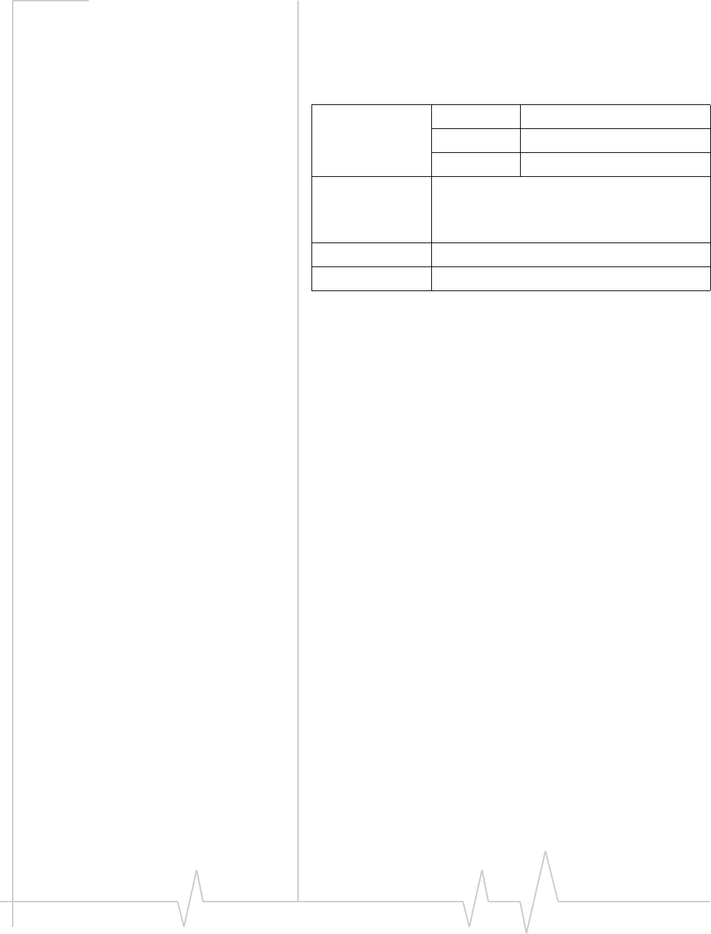
Usage models
Usagemodelscanbeusedtocalculateexpectedcurrent
consumption.AsampleusagemodelisprovidedinTable2‐1.
Thisexamplemodelappliestoabattery‐operateddevice.In
practice,becausethemoduleisisolatedfromthebattery(the
hostdevicemanagesthepowersource),themAhratings
dependonthedevice’ssupplyefficiency.
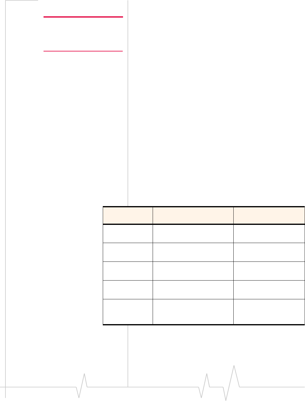
Table 2-1: Power consumption of a sample application
Used by a field worker
(data only) Used for remote data
logging
Upload (module
Tx) 1000 kB/day 40 kB/h
Download
(module Rx) 500 kB/day 100 kB/day
Coverage / data
rate 1X / 80 kbps IS-95 / 14.4 kbps
Hours of
operation 8 / day (off 16 hrs / day) 24 / day
Total power
consumed over
24 hours
60 mAh 200 mAh

CDMA / GSM Mini Card Hardware Integration Guide
14 2130114
Values in this guide are summarized from the product specification documents (PSDs) - the PSD takes precedence.
Themoduleautomaticallyentersslottedsleepmodewhen
thereisnotransmissionorreceptionoccurring(SCI=2).
Transmitpowerisassumedtobe+3dBm.
3
Rev 1.4.1 Mar.07 15
Values in this guide are summarized from the product specification documents (PSDs) - the PSD takes precedence.
3: RF Integration
TheMC87xxoperatesonthefrequenciesdetailedinTable3‐1.
RF connection
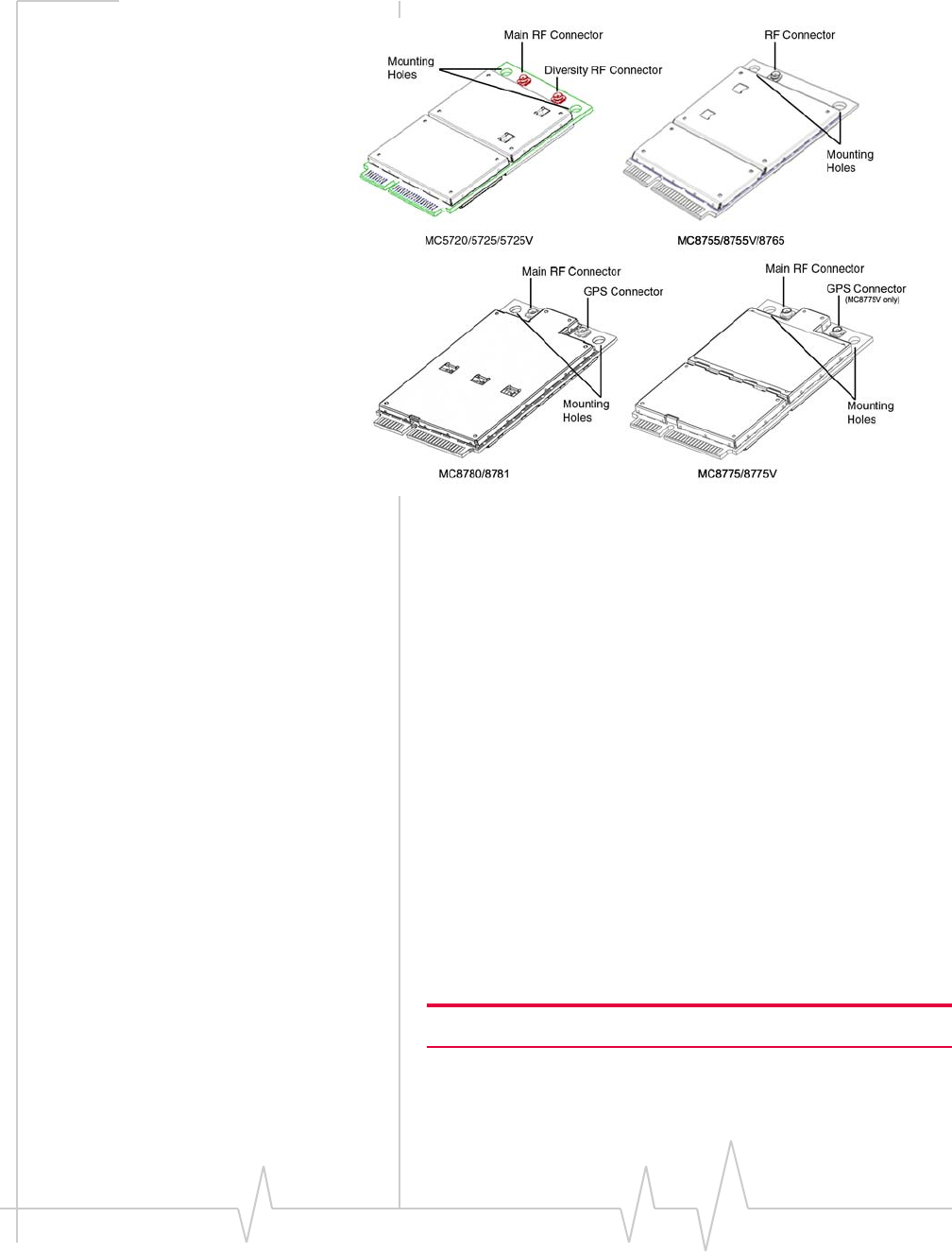
Whenattachinganantennatothemodule:
Note: To disconnect the
antenna, make sure you use the
Hirose U.FL connector removal
tool (P/N UFL-LP-N-2(01)) to
prevent damage to the module
or coaxial cable assembly.
•UseaHiroseU.FLconnector(model
U.FL#CL331‐0471‐0‐10)toattachanantennatoa
connectionpointonthemodule,asshowninFigure3‐1(the
mainRFconnectoronthetopside;thediversityRF
connectoronthebottomside).
•Matchcoaxialconnectionsbetweenthemoduleandthe
antennato50Ω.
•MinimizeRFcablelossestotheantenna;therecommended
maximumcablelossforantennacablingis0.5dB.
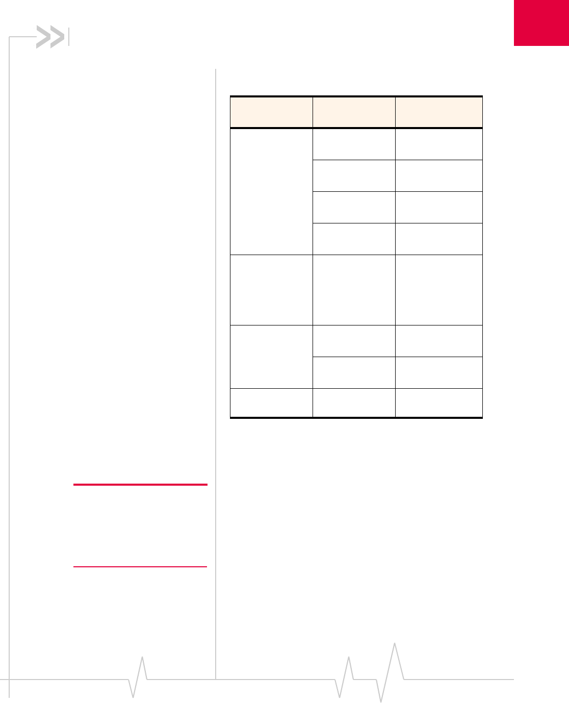
Table 3-1: MC87xx — Supported frequencies
Product Band Frequencies
(MHz)
MC8755 /
MC8755V /
MC8765 /
MC8775 /
MC8775V /
MC8780 /
MC8781
GSM 850 Tx: 824–849
Rx: 869-894
EGSM 900 Tx: 880-915
Rx: 925-960
DCS 1800 Tx: 1710-1785
Rx: 1805-1880
PCS 1900 Tx: 1850-1910
Rx: 1930-1990
MC8755 /
MC8755V /
MC8775 /
MC8775V /
MC8780 /
MC8781
Band I
UMTS 2100 Tx: 1920–1980
Rx: 2110–2170
MC8765 /
MC8775 /
MC8775V /
MC8780 /
MC8781
Band II
UMTS 1900 Tx: 1850–1910
Rx: 1930–1990
Band V
UMTS 850 Tx: 824–849
Rx: 869–894
MC8780 /
MC8781 GPS Rx: 1575.42
CDMA / GSM Mini Card Hardware Integration Guide
16 2130114
In the event of a discrepancy in values between this guide and the Product Specification Document (PSD), the PSD takes precedence.
Figure 3-1: Antenna connection points and mounting holes
Ground connection
Whenconnectingthemoduletosystemground:
•Preventnoiseleakagebyestablishingaverygoodground
connectiontothemodulethroughthehostconnector.
•Connecttosystemgroundusingthetwomountingholesat
thetopofthemodule(asshowninFigure3‐1).
•MinimizegroundnoiseleakageintotheRF.
Dependingonthehostboarddesign,noisecouldpotentially
becoupledtothemodulefromthehostboard.Thisis
mainlyanissueforhostdesignsthathavesignalstraveling
alongthelengthofthemodule,orcircuitryoperatingat
bothendsofthemoduleinterconnects.
Shielding
ThemoduleisfullyshieldedtoprotectagainstEMIandto
ensurecompliancewithFCCPart15‐“RadioFrequency
Devices”(orequivalentregulationsinotherjurisdictions).
Note: The module shields must NOT be removed.

RF Integration
Rev 1.4.1 Mar.07 17
Values in this guide are summarized from the product specification documents (PSDs) - the PSD takes precedence.
Antenna and cabling
Note: Values in this guide are
taken from the appropriate
product specification documents
(PSDs) (listed in
Related
documents
, page 8) — in the
case of a discrepancy between
this document and the relevant
PSD, use the value listed in the
PSD.
Whenselectingtheantennaandcable,itiscriticaltoRFperfor‐
mancetomatchantennagainandcableloss.
Choosing the correct antenna and cabling
Considerthefollowingpointsforpropermatchingofantennas
andcabling:
•Theantenna(andassociatedcircuitry)shouldhavea
nominalimpedanceof50Ωwithareturnloss≤ 10dB
acrosseachfrequencybandofoperation.
•Thesystemgainvalueaffectsbothradiatedpowerand
regulatory(FCC,IC,CE,etc.)testresults.
Developing custom antennas
Considerthefollowingpointswhendevelopingcustom‐
designedantennas:
•AskilledRFengineershoulddothedevelopmenttoensure
thattheRFperformanceismaintained.
•Identifythebandsthatneedtobesupported,particularly
whenboththeMC57xxandMC87xxwillbeinstalledinthe
sameplatform.Inthiscase,youmaywanttodevelop
separateantennasformaximumperformance.
Determining the antenna’s location
Considerthefollowingpointswhendecidingwheretoputthe
antenna:
•AntennalocationmayaffectRFperformance.Althoughthe
moduleisshieldedtopreventinterferenceinmostapplica‐
tions,theplacementoftheantennaisstillveryimportant—
ifthehostdeviceisinsufficientlyshielded,highlevelsof
broadbandorspuriousnoisecandegradethemodule’s
performance.
•Connectingcablesbetweenthemoduleandtheantenna
musthave50Ωimpedance.Iftheimpedanceofthemodule
ismismatched,RFperformanceisreducedsignificantly.
•Antennacablesshouldberouted,ifpossible,awayfrom
noisesources(switchingpowersupplies,LCDassemblies,
etc.).Ifthecablesarenearthenoisesources,thenoisemay
becoupledintotheRFcableandintotheantenna.
Disabling the diversity antenna (MC57xx)
IfyourhostdeviceisnotdesignedtousetheMC57xxmodule’s
diversityantenna,terminatetheinterfacewitha50Ω ohm
load.

CDMA / GSM Mini Card Hardware Integration Guide
18 2130114
In the event of a discrepancy in values between this guide and the Product Specification Document (PSD), the PSD takes precedence.
Interference and sensitivity
Note: These modules are based
on ZIF (Zero Intermediate
Frequency) technologies; when
performing EMC
(Electromagnetic Compatibility)
tests, there are no IF
(Intermediate Frequency)
components from the module to
consider.
SeveralsourcesofinterferencecanaffecttheRFperformance
ofthemodule(RFdesense).Commonsourcesincludepower
supplynoiseanddevice‐generatedRF.
RFdesensecanbeaddressedthroughacombinationof
mitigationtechniquesandradiatedsensitivitymeasurement.
Power supply noise
NoiseinthepowersupplycanleadtonoiseintheRFsignal.
Note: Values in this guide are
taken from the appropriate
product specification documents
(PSDs) (listed in
Related
documents
, page 8) — in the
case of a discrepancy between
this document and the relevant
PSD, use the value listed in the
PSD.
Thepowersupplyripplelimitforthemoduleisnomorethan
200mVp‐p1Hzto100kHz.Thislimitincludesvoltageripple
duetotransmitterburstactivity.
Interference from other wireless devices
Wirelessdevicesoperatinginsidethehostdevicecancause
interferencethataffectsthemodule.
Todeterminethemostsuitablelocationsforantennasonyour
hostdevice,evaluateeachwirelessdevice’sradiosystem,
consideringthefollowing:
•Anyharmonics,sub‐harmonics,orcross‐productsofsignals
generatedbywirelessdevicesthatfallinthemodule’sRx
rangemaycausespuriousresponse,resultingindecreased
Rxperformance.
•TheTxpowerandcorrespondingbroadbandnoiseofother
wirelessdevicesmayoverloadorincreasethenoisefloorof
themodule’sreceiver,resultinginRxdesense.
Theseverityofthisinterferencedependsontheclosenessof
theotherantennastothemodule’santenna.Todetermine
suitablelocationsforeachwirelessdevice’santenna,
thoroughlyevaluateyourhostdevice’sdesign.

RF Integration
Rev 1.4.1 Mar.07 19
Values in this guide are summarized from the product specification documents (PSDs) - the PSD takes precedence.
Device-generated RF
Note: The module can cause
interference with other devices
such as hearing aids and on-
board speakers.
Wireless devices such as the
Mini Card transmit in bursts
(pulse transients) for set
durations (RF burst frequencies).
Hearing aids and speakers
convert these burst frequencies
into audible frequencies,
resulting in audible noise.
AllelectroniccomputingdevicesgenerateRFinterferencethat
cannegativelyaffectthereceivesensitivityofthemodule
(RFdesense).
Theproximityofhostelectronicstotheantennainwireless
devicescancontributetoRFdesense.Componentsthatare
mostlikelytocauseRFdesenseinclude:
•Microprocessorandmemory
•Displaypanelanddisplaydrivers
•Switching‐modepowersupplies
Theseandotherhigh‐speeddevices(inparticular,the
processor)cancauseRFdesensebecausetheyrunat
frequenciesoftensofMHz.Therapidriseandfallofthese
clocksignalsgenerateshigher‐orderharmonicsthatoftenfall
withintheoperatingfrequencybandofthemodule,causing
RFdesense.
Example
Onasub‐systemrunningat40MHz,the22ndharmonicfalls
at880MHz,whichiswithinthecellularreceivefrequency
band.
Note: In practice, there are usually numerous interfering frequencies
and harmonics. The net effect can be a series of desensitized receive
channels.
Note: It is important to
investigate sources of localized
interference early in the design
cycle.

CDMA / GSM Mini Card Hardware Integration Guide
20 2130114
In the event of a discrepancy in values between this guide and the Product Specification Document (PSD), the PSD takes precedence.
4
Rev 1.4.1 Mar.07 21
Values in this guide are summarized from the product specification documents (PSDs) - the PSD takes precedence.
4: Host / Module Communication
Interface
ThischapterprovidesinformationabouttheHost‐Module
communicationinterface(USBinterface)andliststheextended
ATcommandsthatmaybeusefulforhardwareintegration
testing.
Note: On any given interface (USB, USIM/RUIM, etc.), leave unused
inputs and outputs as no-connects.
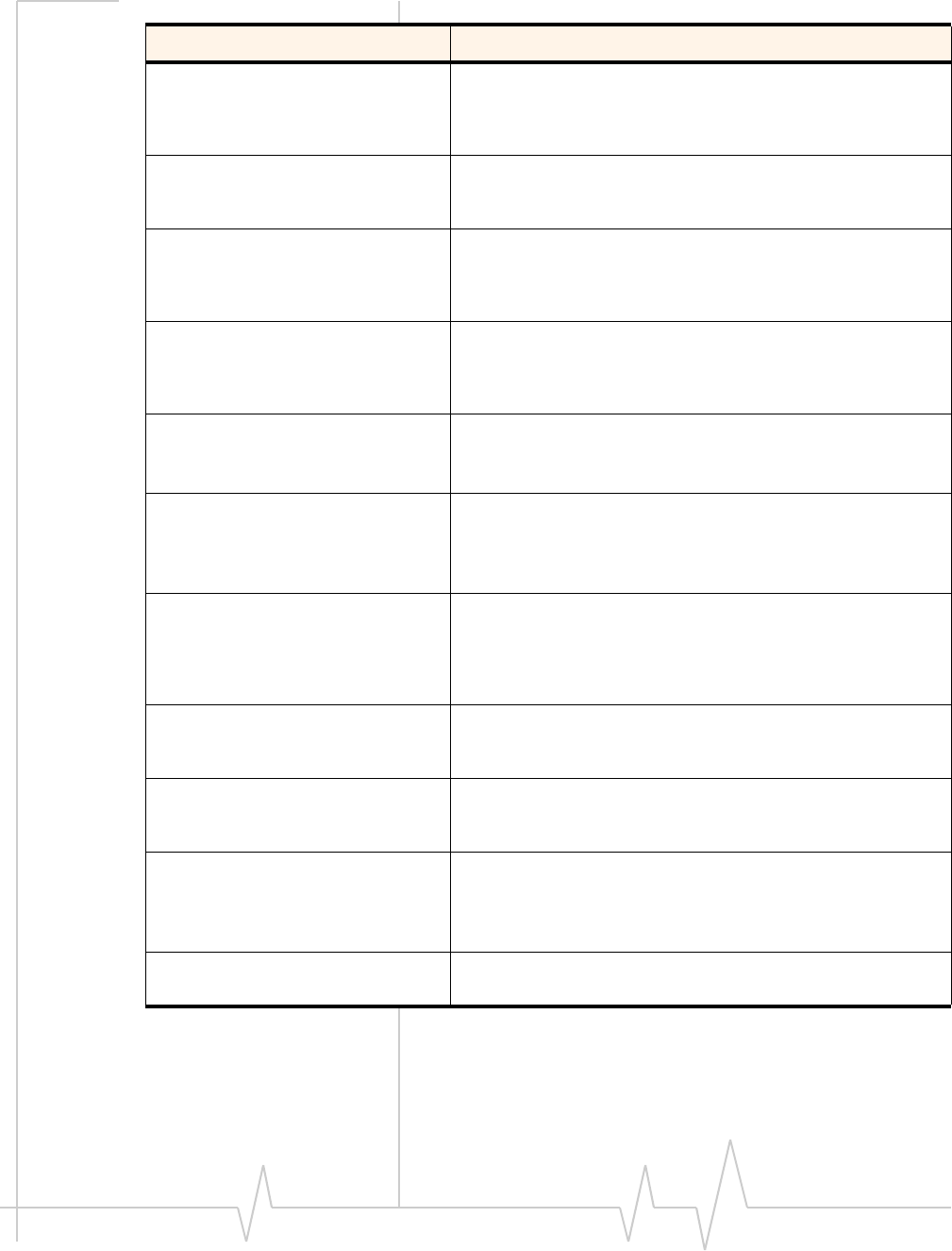
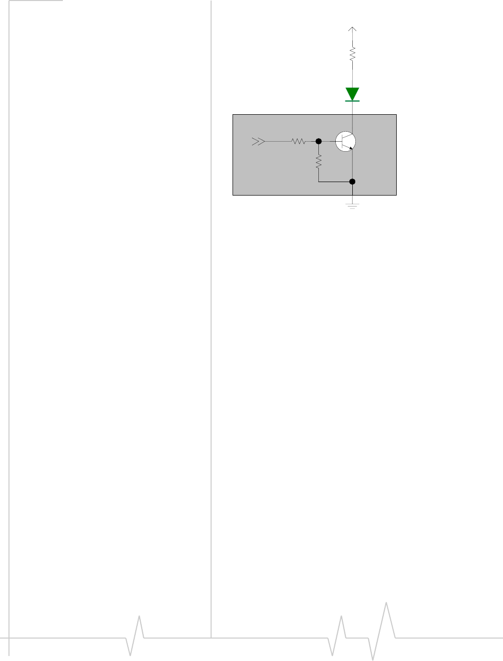
LED output
ThemoduledrivestheLEDoutputaccordingtothePCI‐
ExpressMiniCardspecification(summarizedinTable4‐1,
below).
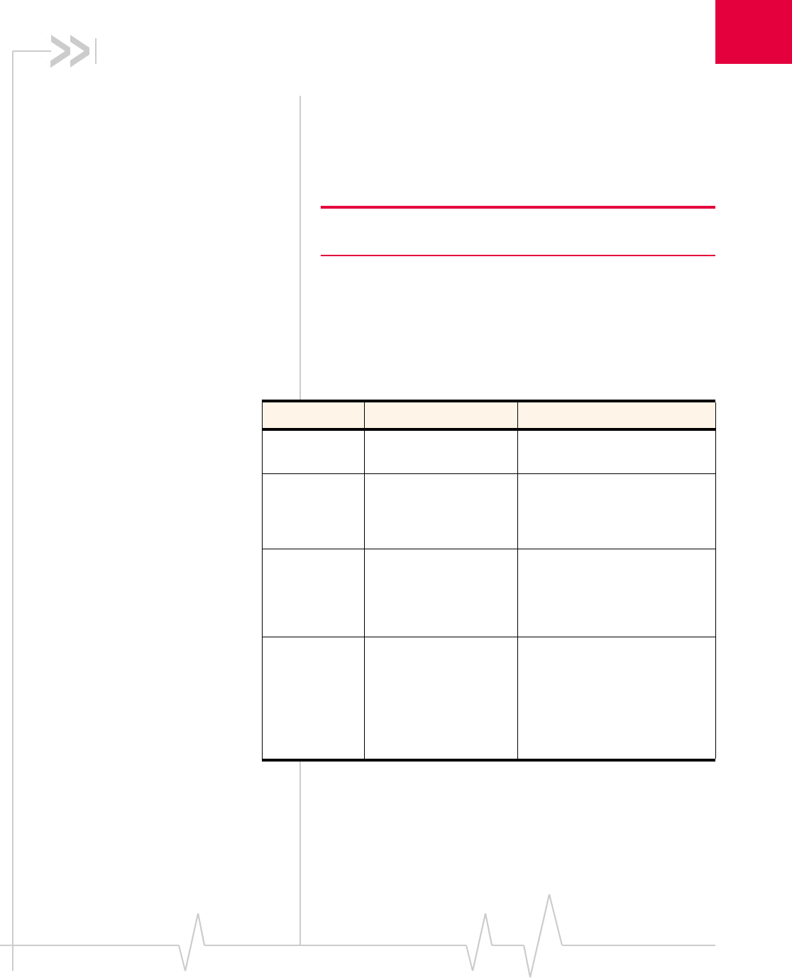
Table 4-1: LED states
State Indicates Characteristics
Off Module is not
powered. Light is off.
On Module is powered
and connected, but
not transmitting or
receiving.
Light is on.
Slow blink Module is powered
and searching for a
connection.
LED is flashing at a steady,
slow rate.
•250 ms ± 25% ON period
•0.2 Hz ± 25% blink rate
Intermittent
blink Module is transmitting
or receiving. LED is flashing intermittently,
proportional to data transfer
activity.
•50% duty cycle
•3 Hz minimum blink rate
•20 Hz maximum blink rate
CDMA / GSM Mini Card Hardware Integration Guide
22 2130114
Values in this guide are summarized from the product specification documents (PSDs) - the PSD takes precedence.
Figure 4-1: Example LED
Current limiting Resistor
LED
VCC 3.3V
MIO
MiniCard

A
Rev 1.4.1 Mar.07 23
A: Regulatory Information
Important notice
Becauseofthenatureofwirelesscommunications,trans‐
missionandreceptionofdatacanneverbeguaranteed.Data
maybedelayed,corrupted(i.e.,haveerrors)orbetotallylost.
Althoughsignificantdelaysorlossesofdataarerarewhen
wirelessdevicessuchastheSierraWirelessmodemareusedin
anormalmannerwithawell‐constructednetwork,theSierra
Wirelessmodemshouldnotbeusedinsituationswherefailure
totransmitorreceivedatacouldresultindamageofanykind
totheuseroranyotherparty,includingbutnotlimitedto
personalinjury,death,orlossofproperty.SierraWirelessand
itsaffiliatesacceptnoresponsibilityfordamagesofanykind
resultingfromdelaysorerrorsindatatransmittedorreceived
usingtheSierraWirelessmodem,orforfailureoftheSierra
Wirelessmodemtotransmitorreceivesuchdata.
Safety and hazards
DonotoperateyourMC57xx/MC87xxmodem:
•Inareaswhereblastingisinprogress
•Whereexplosiveatmospheresmaybepresentincluding
refuellingpoints,fueldepots,andchemicalplants
•Nearmedicalequipment,lifesupportequipment,orany
equipmentwhichmaybesusceptibletoanyformofradio
interference.Insuchareas,theMC57xx/MC87xxmodem
MUSTBEPOWEREDOFF.Otherwise,theMC57xx/
MC87xxmodemcantransmitsignalsthatcouldinterfere
withthisequipment.
Inanaircraft,theMC57xx/MC87xxmodemMUSTBE
POWEREDOFF.Otherwise,theMC57xx/MC87xxmodem
cantransmitsignalsthatcouldinterferewithvariousonboard
systemsandmaybedangeroustotheoperationoftheaircraft
ordisruptthecellularnetwork.Useofacellularphoneinan
aircraftisillegalinsomejurisdictions.Failuretoobservethis
instructionmayleadtosuspensionordenialofcellular
telephoneservicestotheoffender,orlegalactionorboth.
Someairlinesmaypermittheuseofcellularphoneswhilethe
aircraftisonthegroundandthedoorisopen.TheMC57xx/
MC87xxmodemmaybeusednormallyatthistime.

CDMA / GSM Mini Card Hardware Integration Guide
24 2130114
Important compliance
information for North American
users
TheMC57xx/MC87xxmodemhasbeengrantedmodular
approvalformobileapplications.Integratorsmayusethe
MC57xx/MC87xxmodemintheirfinalproductswithout
additionalFCC/IC(IndustryCanada)certificationifthey
meetthefollowingconditions.Otherwise,additionalFCC/IC
approvalsmustbeobtained.
1. Atleast20cmseparationdistancebetweentheantennaand
theuser’sbodymustbemaintainedatalltimes.
2. TocomplywithFCC/ICregulationslimitingbothmaximum
RFoutputpowerandhumanexposuretoRFradiation,the
maximumantennagainincludingcablelossinamobile‐only
exposureconditionmustnotexceed:
·8dBiintheCellularbandand4dBiinthePCSbandforthe
MC8755/MC8765
·5dBiintheCellularbandand4dBiinthePCSbandforthe
MC8775/MC8780/MC8781
·4.65dBiintheCellularbandand3.35dBiinthePCSband
fortheMC5720/MC5725
3. TheMC57xx/MC87xxmodemanditsantennamustnot
beco‐locatedoroperatinginconjunctionwithanyother
transmitterorantennawithinahostdevice.
4. Alabelmustbeaffixedtotheoutsideoftheendproductinto
whichtheMC57xx/MC87xxmodemisincorporated,with
astatementsimilartothefollowing:
·ForMC5720:
ThisdevicecontainsFCCID:N7N‐MC5720
Thisequipmentcontainsequipmentcertifiedunder
IC:2417C‐MC5720
·ForMC5725/MC5725V:
ThisdevicecontainsFCCID:N7N‐MC5725
Thisequipmentcontainsequipmentcertifiedunder
IC:2417C‐MC5725
·ForMC8755/MC8755V:
ThisdevicecontainsFCCID:N7NMC8755
·ForMC8765:
ThisdevicecontainsFCCID:N7NMC8765
Thisequipmentcontainsequipmentcertifiedunder
IC:2417C‐MC8765
·ForMC8775/MC8775V:
ThisdevicecontainsFCCID:N7NMC8775
Thisequipmentcontainsequipmentcertifiedunder
IC:2417C‐MC8775
·ForMC8780:
ThisdevicecontainsFCCID:N7NMC8780

Regulatory Information
Rev 1.4.1 Mar.07 25
·ForMC8781:
ThisdevicecontainsFCCID:N7NMC8781
Thisequipmentcontainsequipmentcertifiedunder
IC:2417C‐MC8781
5. Ausermanualwiththeendproductmustclearlyindicatethe
operatingrequirementsandconditionsthatmustbeobserved
toensurecompliancewithcurrentFCC/ICRFexposure
guidelines.
TheendproductwithanembeddedMC57xx/MC87xx
modemmayalsoneedtopasstheFCCPart15unintentional
emissiontestingrequirementsandbeproperlyauthorizedper
FCCPart15.
Note:Ifthismoduleisintendedforuseinaportabledevice,
youareresponsibleforseparateapprovaltosatisfytheSAR
requirementsofFCCPart2.1093andICRSS‐102.

CDMA / GSM Mini Card Hardware Integration Guide
26 2130114
B
Rev 1.4.1 Mar.07 27
B: Acronyms and Definitions
.
Table B-2: Acronyms and definitions
Acronym or term Definition
AGC Automatic Gain Control
BER Bit Error Rate - a measure of receive sensitivity
BLER Block Error Rate
Call Box Base Station Simulator - Agilent E8285A or 8960, Rohde &
Schwarz CMU200
CDMA Code Division Multiple Access
dB Decibel = 10 x log10 (P1/P2)
P1 is calculated power; P2 is reference power
Decibel = 20 x log10 (V1/V2)
V1 is calculated voltage, V2 is reference voltage
dBm Decibels, relative to 1 mW - Decibel(mW) = 10 x log10 (Pwr (mW)/
1mW)
DUT Device Under Test
EDGE Enhanced Data rates for GSM Evolution
EM Embedded Module
ESD ElectroStatic Discharge
FER Frame Error Rate - a measure of receive sensitivity
GPRS General Packet Radio Services
GPS Global Positioning System
GSM Global System for Mobile communications
Hz Hertz = 1 cycle/second
inrush current Peak current drawn when a device is connected or powered on
IS-2000 3G radio standards for voice and data (CDMA only)
IS-95 2G radio standards targeted for voice (cdmaONE)
LDO Low Drop Out - refers to linear regulator
MC5720 / MC5725 /
MC5725V Sierra Wireless Mini Cards used on CDMA networks
CDMA / GSM Mini Card Hardware Integration Guide
28 2130114
MC57xx Any of the following CDMA Mini Cards: MC5720 / MC5725
MC8755 / MC8755V /
MC8765 /
MC8775 / MC8775V
Sierra Wireless Mini Cards used on GSM networks
MC87xx Any of the following CDMA Mini Cards: MC8755 / MC8755V /
MC8765 / MC8775 / MC8775V
MHz MegaHertz = 10E6 Hertz (Hertz = 1 cycle/second)
MIO Module Input/Output
MP Mobile Product
MPE Maximum Permissible Exposure — the level of radiation to which a
person may be exposed without hazardous effect or adverse
biological changes
OTA Over-The-Air or Radiated through the antenna
PCS Personal Communication System - PCS spans the 1.9 GHz radio
spectrum
RF Radio Frequency
RMS Root Mean Square
RUIM Removable User Identity Module
SA Selective Availability
Sensitivity (Audio) Measure of lowest power signal that the receiver can measure
Sensitivity (RF) Measure of lowest power signal at the receiver input that can
provide a prescribed BER/BLER/SNR value at the receiver output.
SIM Subscriber Identity Module
SNR Signal to Noise Ratio
SOF Start of Frame - a USB function
UART Universal Asynchronous Receiver Transmitter
UDK Universal Development Kit (PCI Express Mini Card Dev Kit)
UMTS Universal Mobile Telecommunications System
USB Universal Serial Bus
USIM Universal Subscriber Identity Module
VCC3.3 3.3 V supply voltage
Table B-2: Acronyms and definitions
Acronym or term Definition
Acronyms and Definitions
Rev 1.4.1 Mar.07 29
WCDMA Wideband Code Division Multiple Access — In this document, the
term “UMTS” is used instead of “WCDMA”.
XIM In this document, XIM is used as part of the contact identifiers for
the USIM/RUIM interface (XIM_VCC, XIM_CLK, etc.). It indicates
either RUIM or USIM.
Table B-2: Acronyms and definitions
Acronym or term Definition

CDMA / GSM Mini Card Hardware Integration Guide
30 2130114

Rev 1.4.1 Mar.07 31
Index
Numerics
1X
CDMAStandard 9
A
acronymsanddefinitions 27–29
airplanemode 13
antenna
connectionandmountingpoints 16
connectionconsiderations 15
custom,considerations 17
diversityantenna,disabling 17
limit,matchingcoaxialconnections 15
location,considerations 17
matching,considerations 17
maximumcableloss 15
ATcommands
3GPPspecification,details 9
lowpowermode,setting 13
ATcommands,extended
MC5720/MC5725,reference 9
MC87xx,reference 10
ATcommands,standard
MC5720/MC5725,reference 9
MC87xx,reference 10
C
cableloss
antenna,maximum 15
CDMA
1XStandard 9
CnS
MC5720/MC5725reference 9
MC87xxreference 10
connection
grounding 16
connectors,required
EDGEmating(52‐pin) 8
host‐module 8
RF,Hirose 8
USIM/RUIM 8
current
consumption
usagemodels 13
D
DCS1800
RFparameters,MC8755/8765/8775 15
desense.SeeRF
disconnected,modulepowerstate 12
diversityantenna
disabling 17
E
EDGEconnector,manufacturers 8
EGSM900
RFparameters,MC8755/8765/8775 15
electrostaticdischarge.SeeESD
ESD
protectionrequirements 11–12
testingtechniquesdocument(IEC‐61000‐4‐2) 9
F
FCC
regulations,relevantsection 9
G
grounding
connectionconsiderations 16
GSM850
RFparameters,MC8755/8765/8775 15
I
impedance
module‐antenna 17
interference
devicegenerated 19
powersupplynoise 18
wirelessdevices 18
L
LED
example 22
state
intermittentblink 21
off 21
on 21
slowblink 21
lowpowermode
setting,ATcommands 13
lowpower,modulepowerstate 13
M
MC5720
ATreference(extended),andMC5725 9
ATreference(standard),andMC5725 9

CDMA / GSM Mini Card Hardware Integration Guide
32 2130114
CnSreference,andMC5725 9
productspecification 9
MC5725
ATreference(extended),andMC5720 9
ATreference(standard),andMC5720 9
CnSreference,andMC5720 9
productspecification 9
MC5725V
productspecification 9
MC8755
ATreference(extended),andMC87xx 10
ATreference(standard),andMC87xx 10
CnSreference,andMC87xx 10
productspecification 9
MC8755/8765/8775
RFparameters 15
MC8755V
ATreference(extended),andMC87xx 10
ATreference(standard),andMC87xx 10
CnSreference,andMC87xx 10
productspecification 10
MC8765
ATreference(extended),andMC87xx 10
ATreference(standard),andMC87xx 10
CnSreference,andMC87xx 10
productspecification 9
MC8775
ATreference(extended),andMC87xx 10
ATreference(standard),andMC87xx 10
CnSreference,andMC87xx 10
productspecification 10
MC8775V
ATreference(extended),andMC87xx 10
ATreference(standard),andMC87xx 10
CnSreference,andMC87xx 10
productspecification 10
MiniCard
DevKitQuickStartGuide 10
PCIExpressSpecification 10
N
noise
leakage,minimizing 16
RFinterference,powersupply 18
normal,modulepowerstate 13
O
off,modulepowerstate 12
P
PCIExpress
MiniCardspecification 10
PCS1900
RFparameters,MC8755/8765/8775 15
power
defaultstate 13
disconnected,characteristics 12
normal,characteristics 13
off,characteristics 12
signals,overview 11
state,disconnected 12
state,lowpower 13
state,normal 13
state,off 12
supply,RFinterference 18
supply,ripplelimit 18
powerinterface 11–14
ProductSpecificationDocument.SeePSD
PSD
MC5720 9
MC5725 9
MC5725V 9
MC8755/8765 9
MC8755V 10
MC8775 10
MC8775V 10
R
regulatoryinformation
FCC 24
limitationofliability 23
safetyandhazards 23
RF
antennacableloss,maximum 15
antennaconnection,considerations 15
cabletype,required 8
desense
device‐generated 19
interference
otherdevices 19
powersupply 18
wirelessdevices 18
parameters
DCS1800 15
EGSM900 15
GSM850 15
MC8755/8765/8775 15
PCS1900 15
UMTS1900 15
UMTS2100 15
UMTS850 15
S
SeealsoMC5720,MC5725,MC5725V,MC8755,
MC8755V,MC8765,MC8775,MC8775V 10
shielding
module,compliance 16
SIM
testingmethods,MSconformancespecification 10
SIM.SeeUSIM/RUIM

Index
Rev 1.4.1 Mar.07 33
T
testing
ESDimmunity,techniquesdocument(IEC‐61000‐
4‐2) 9
U
UDK.SeeUniversalDevelopmentKit
UMTS1900
RFparameters,MC8755/8765/8775 15
UMTS2100
RFparameters,MC8755/8765/8775 15
UMTS850
RFparameters,MC8755/8765/8775 15
UniversalDevelopmentKit
components,included 7
UniversalSerialBus.SeeUSB
usagemodels
currentconsumption 13
USB
specification 10
USIM/RUIM
connectortype,required 8
W
W_Disable#
Normalstate 13
offstate 12
powerstate,controlling 11
Z
ZIF(ZeroIntermediateFrequency) 18

CDMA / GSM Mini Card Hardware Integration Guide
34 2130114
