Sierra Wireless Q2438F-M TRI MODE CDMA WIRELESS MODULE KIT User Manual Starter Kit V2 User Guide
Sierra Wireless, Inc. TRI MODE CDMA WIRELESS MODULE KIT Starter Kit V2 User Guide
Contents
- 1. USERS MANUAL
- 2. Manual 1
- 3. Manual 2
- 4. Manual 3
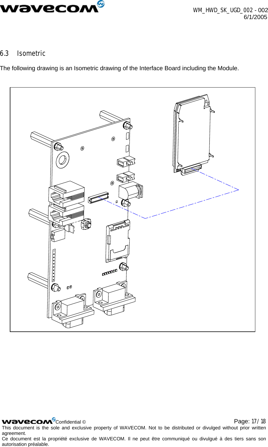
USERS MANUAL