Simcom 1403022014008 WCDMA/HSDPA Module User Manual SIM5320AL EVB User Guide
Shanghai Simcom Ltd. WCDMA/HSDPA Module SIM5320AL EVB User Guide
Simcom >
Contents
- 1. SIM5320AL_User Manual
- 2. SIM5320AL_EVB_User Guide
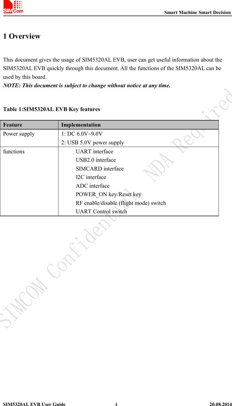
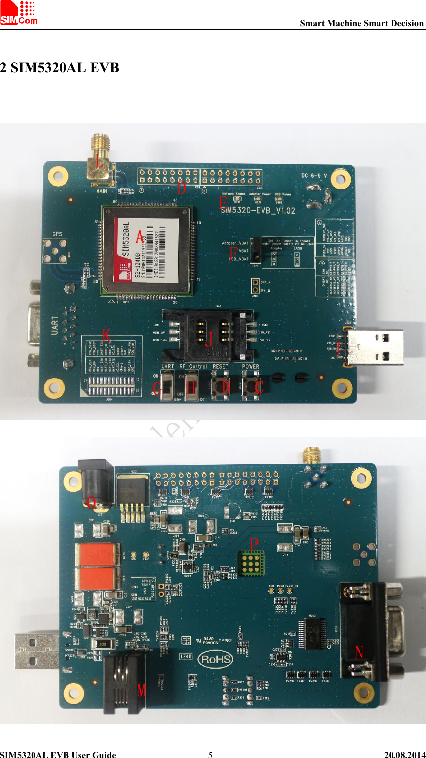
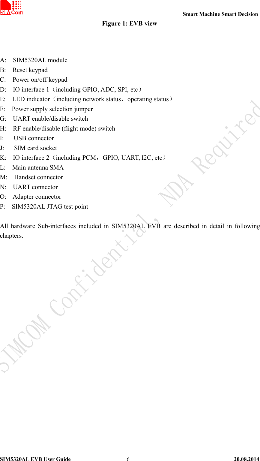
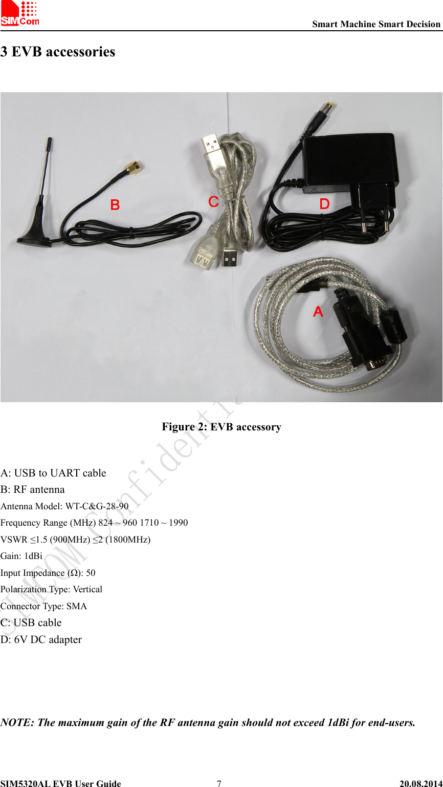
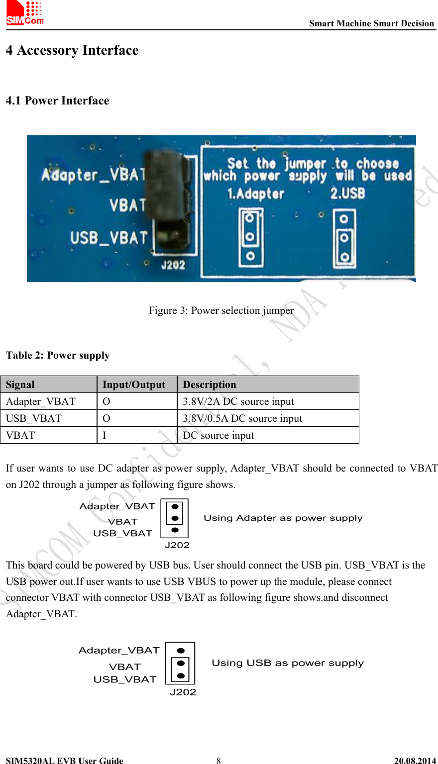
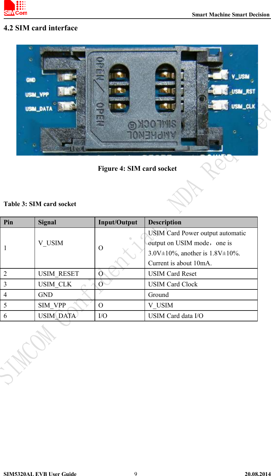
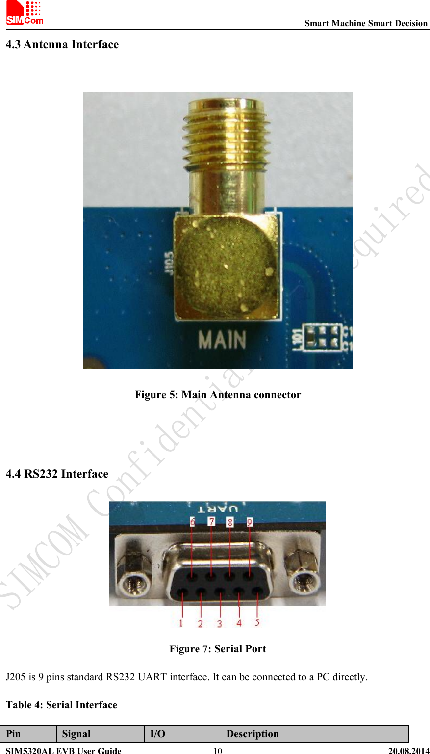
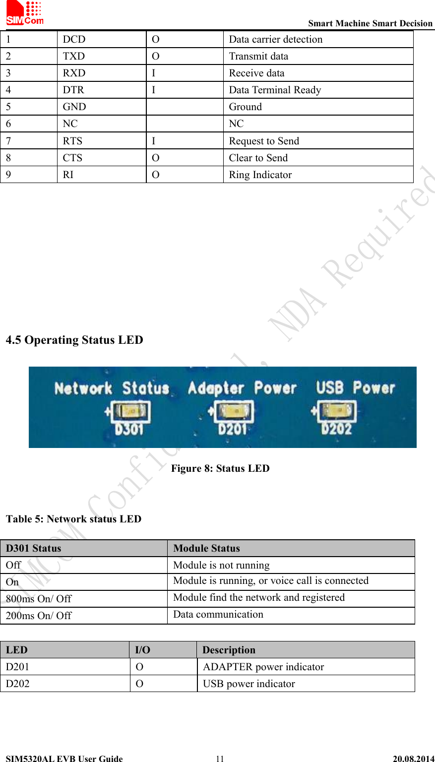
SIM5320AL_EVB_User Guide