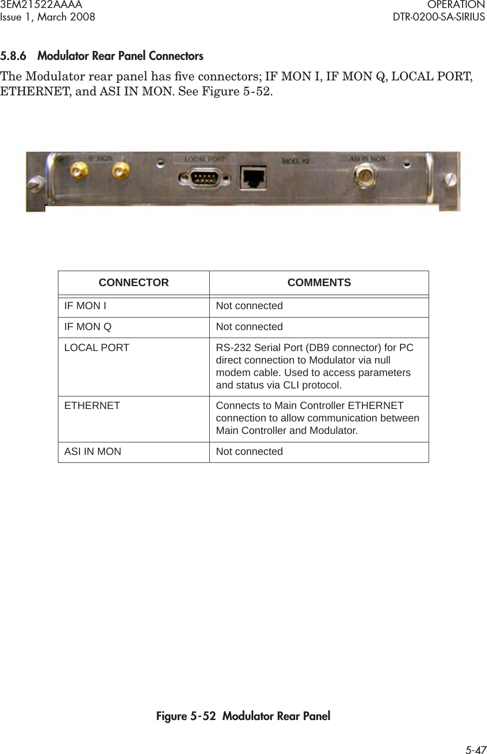
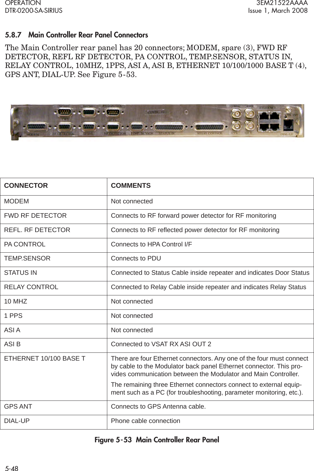
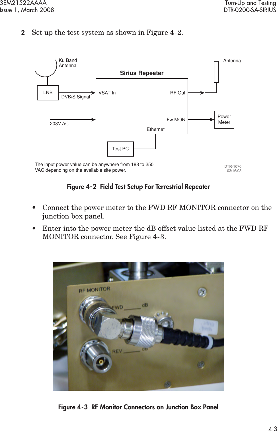
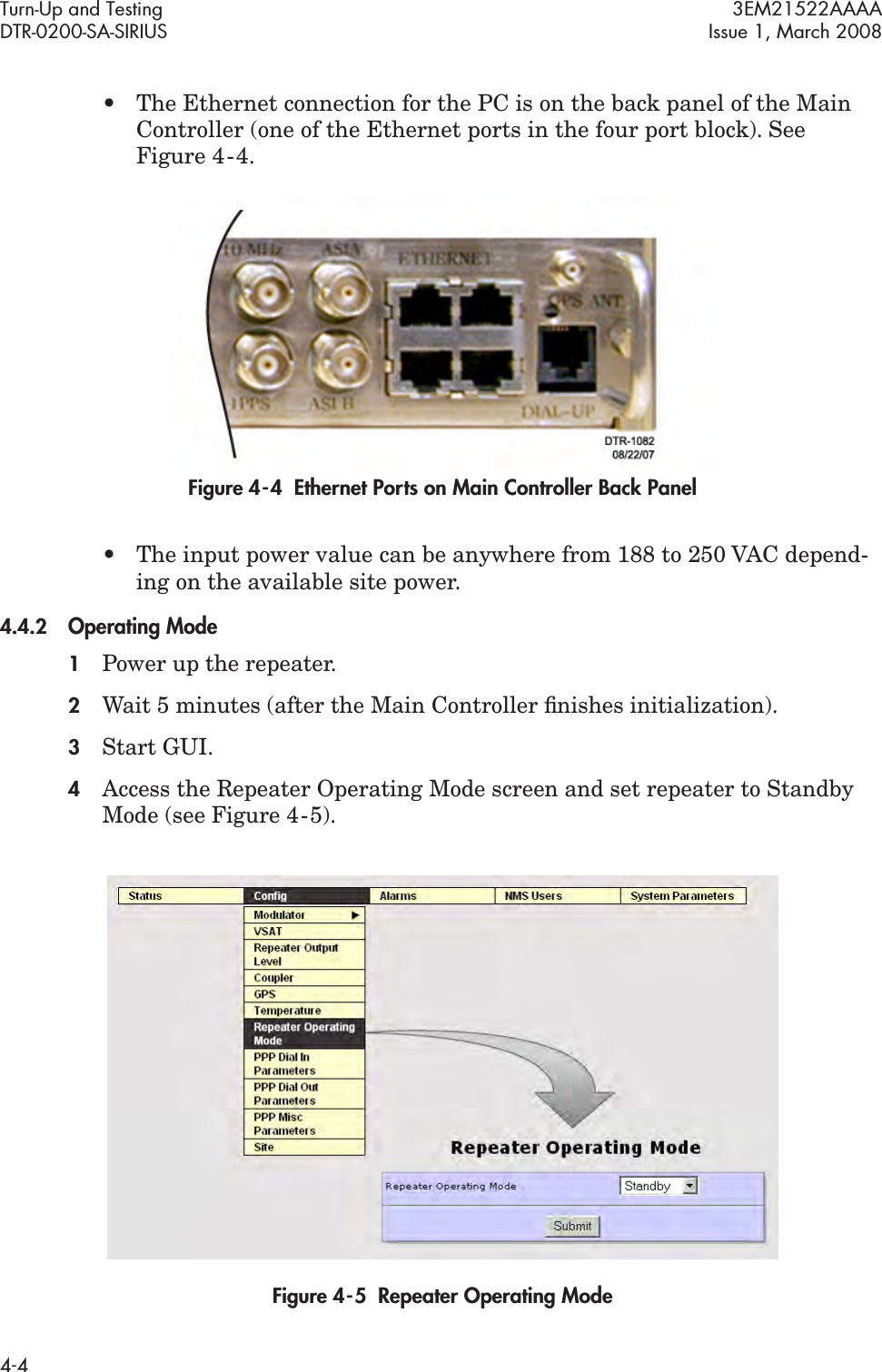
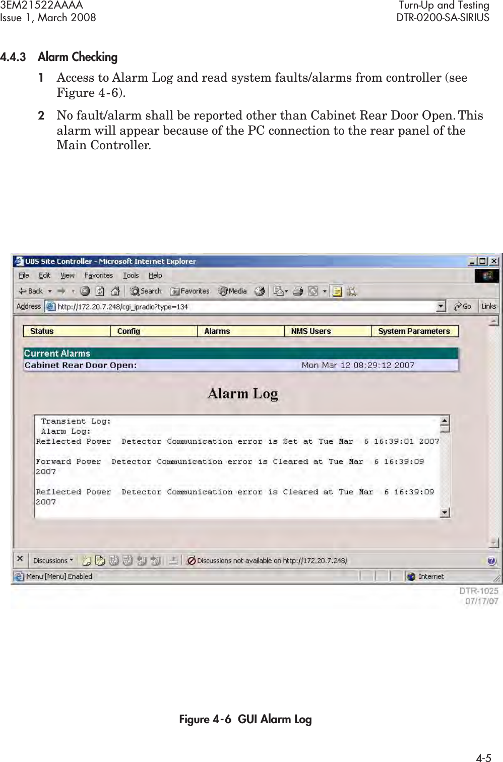
Sirius XM Radio DTR0200 ALU Repeater User Manual 00 DTR Iss 1
Sirius XM Radio Inc. ALU Repeater 00 DTR Iss 1
UserManual.wiki
>
Sirius XM Radio
>
DTR0200 User Manual
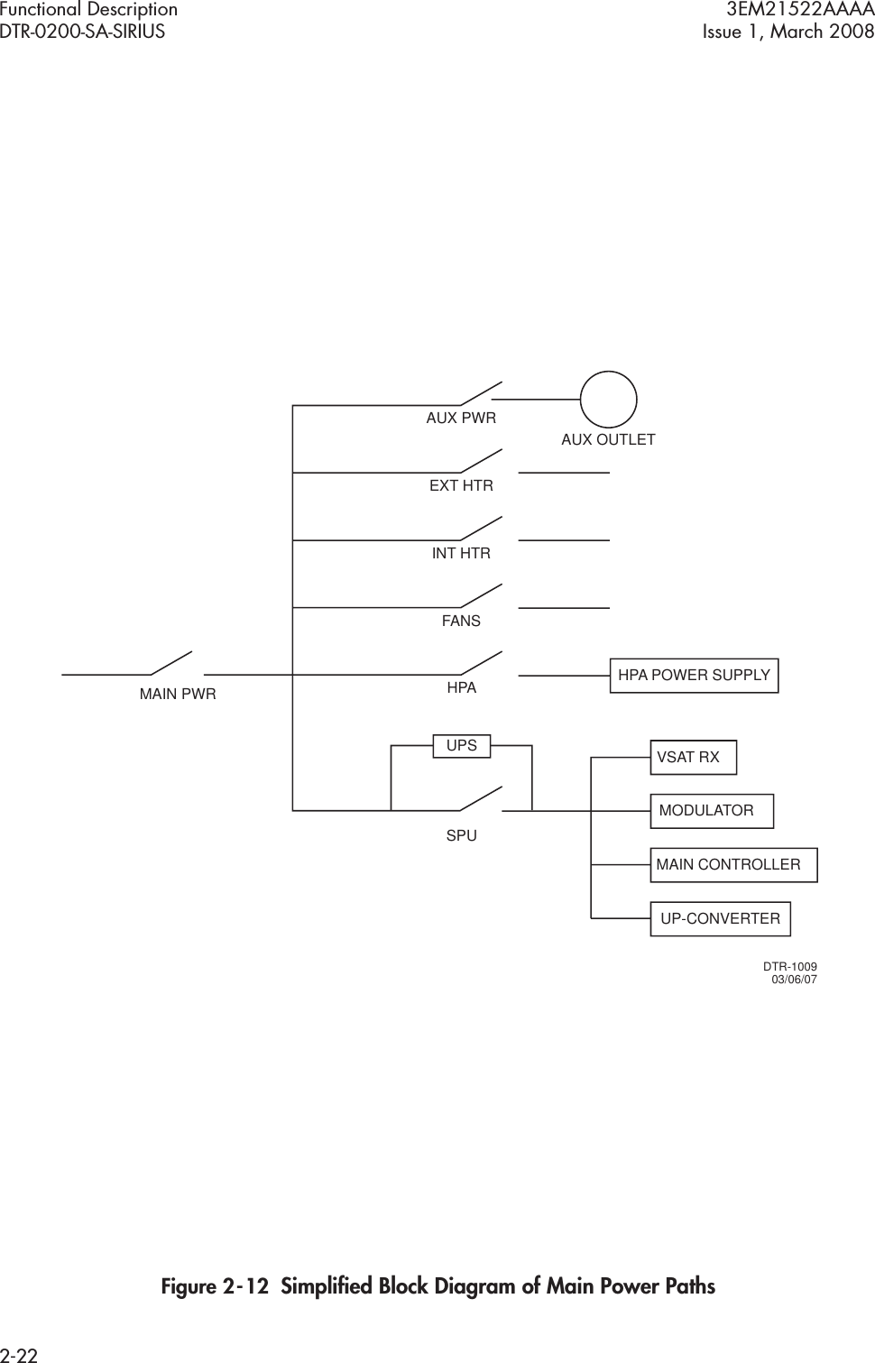
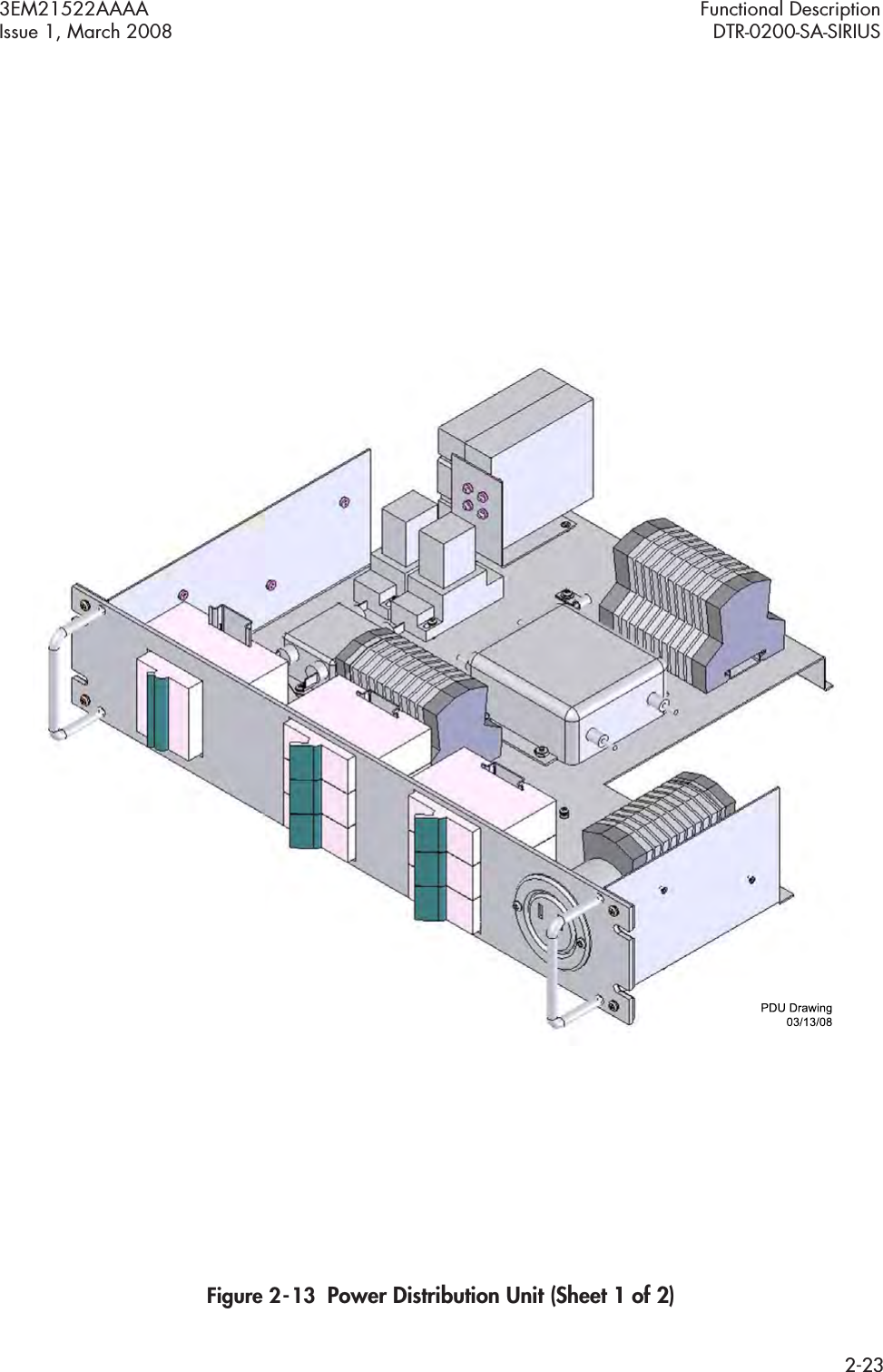
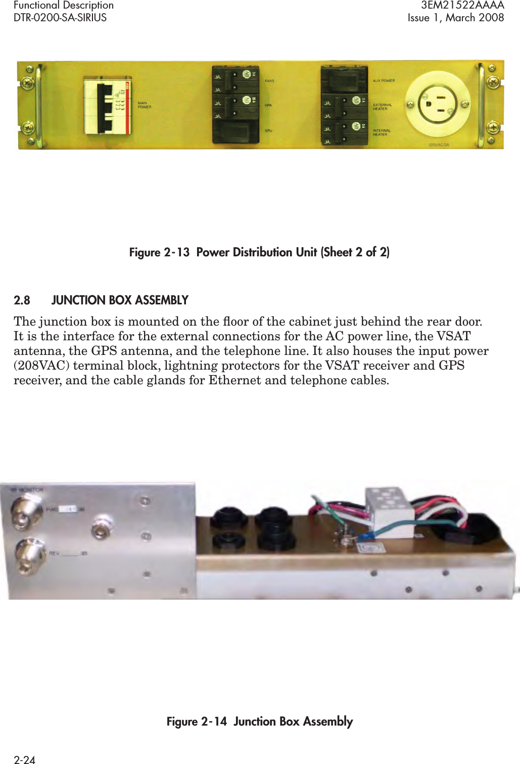
>
Users Manual Part 1
Contents
1.
Users Manual Part 1
2.
Users Manual Part 2
Users Manual Part 1
Navigation menu
Upload a User Manual
Namespaces
Wiki Guide
HTML
PDF
Info
Views
User Manual
Discussion / Help
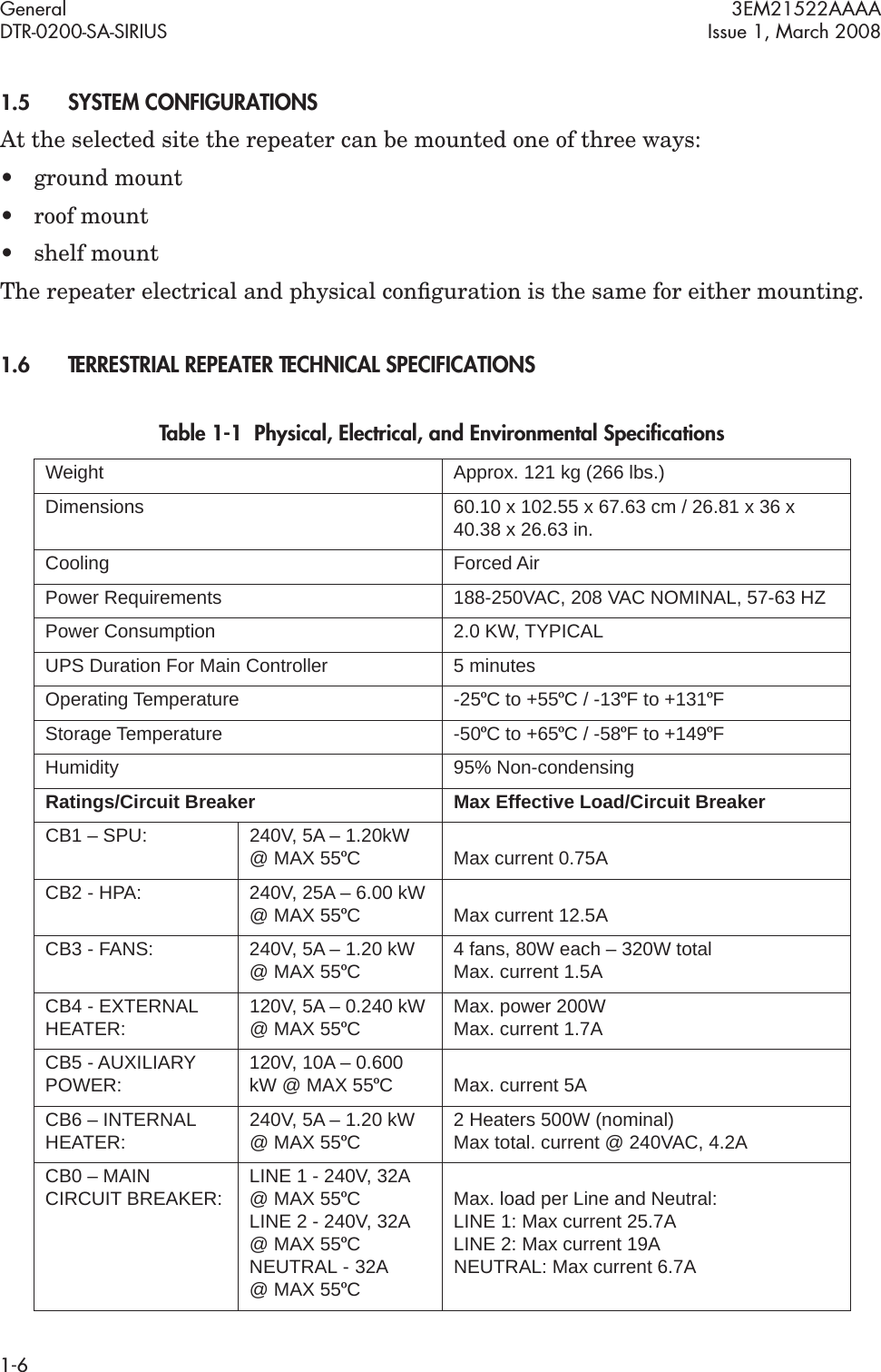
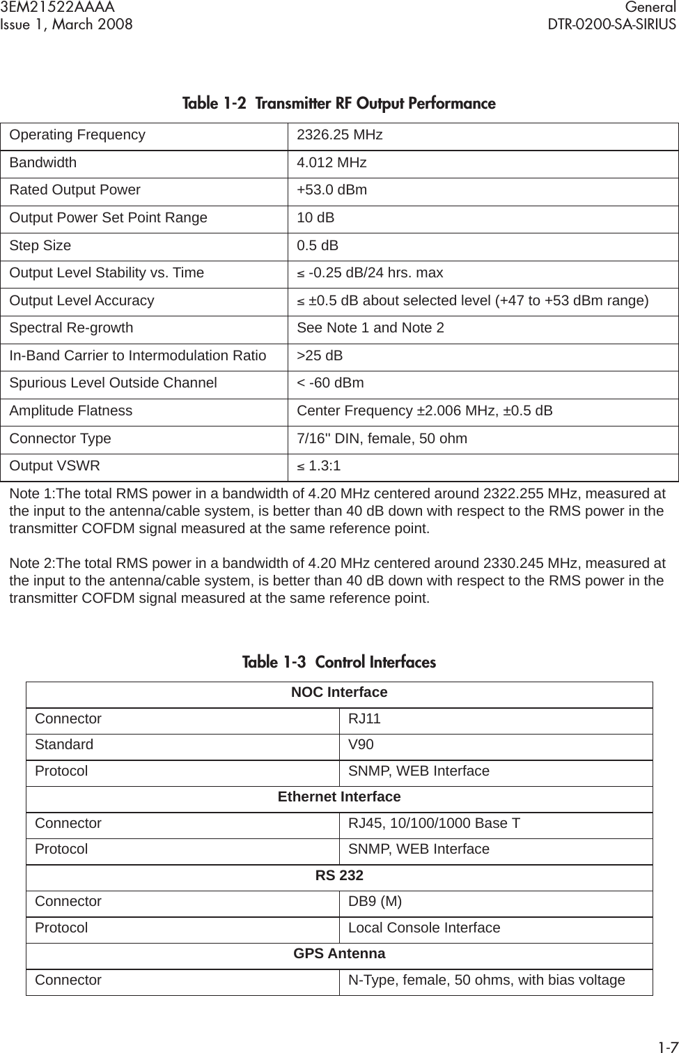
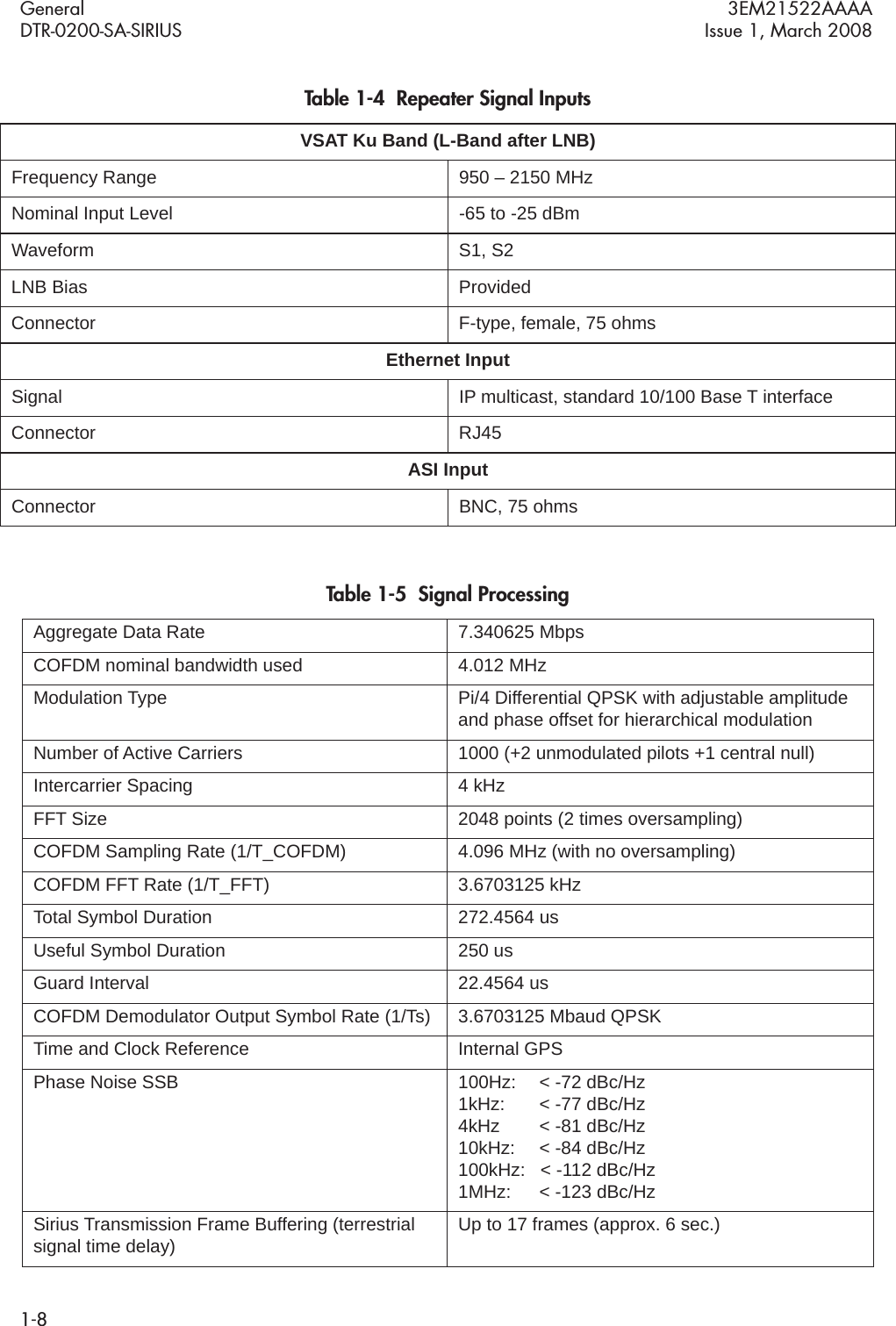
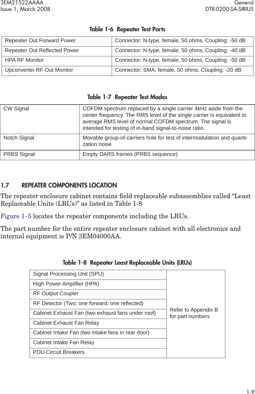
Navigation


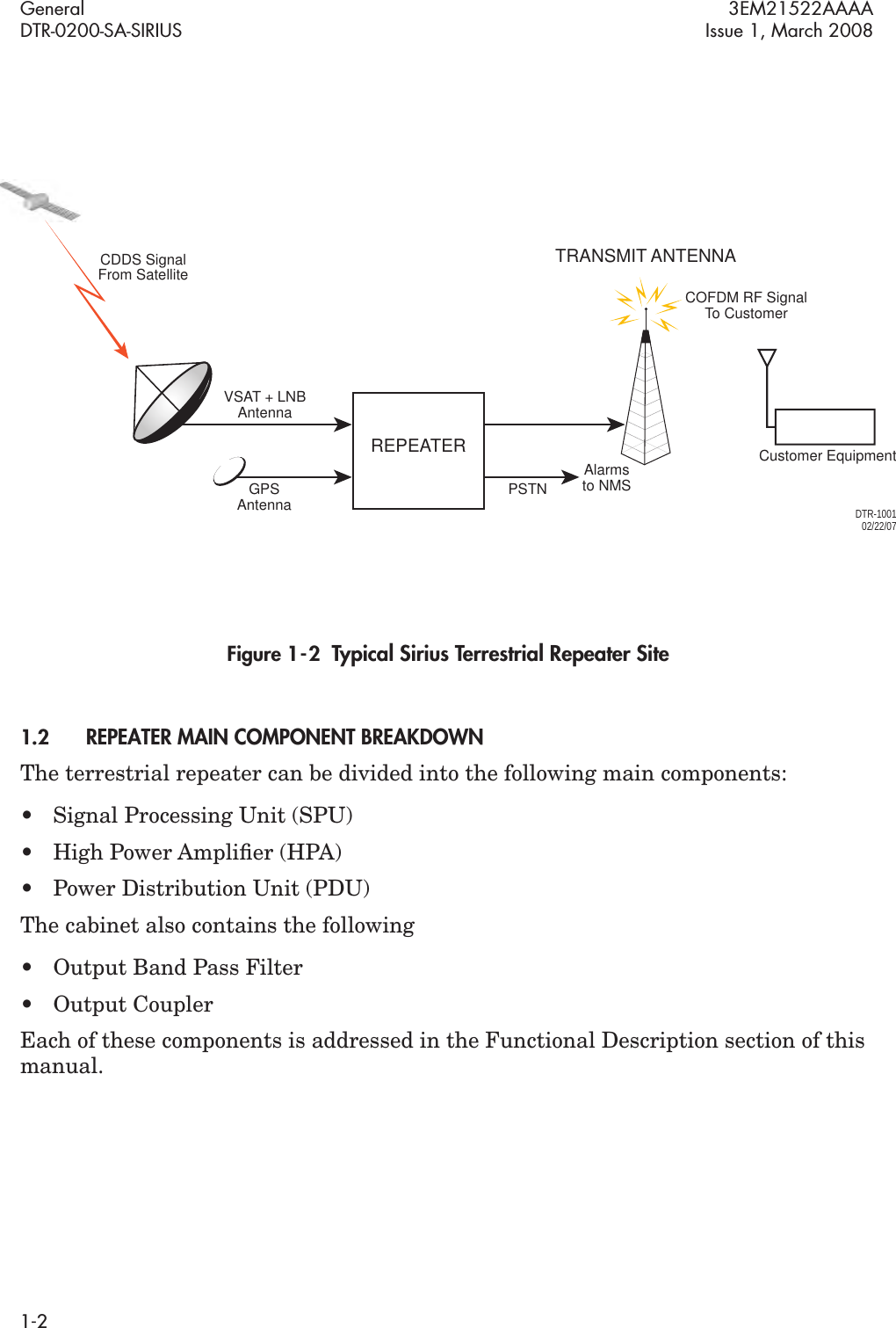
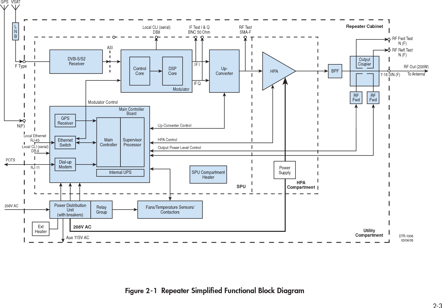

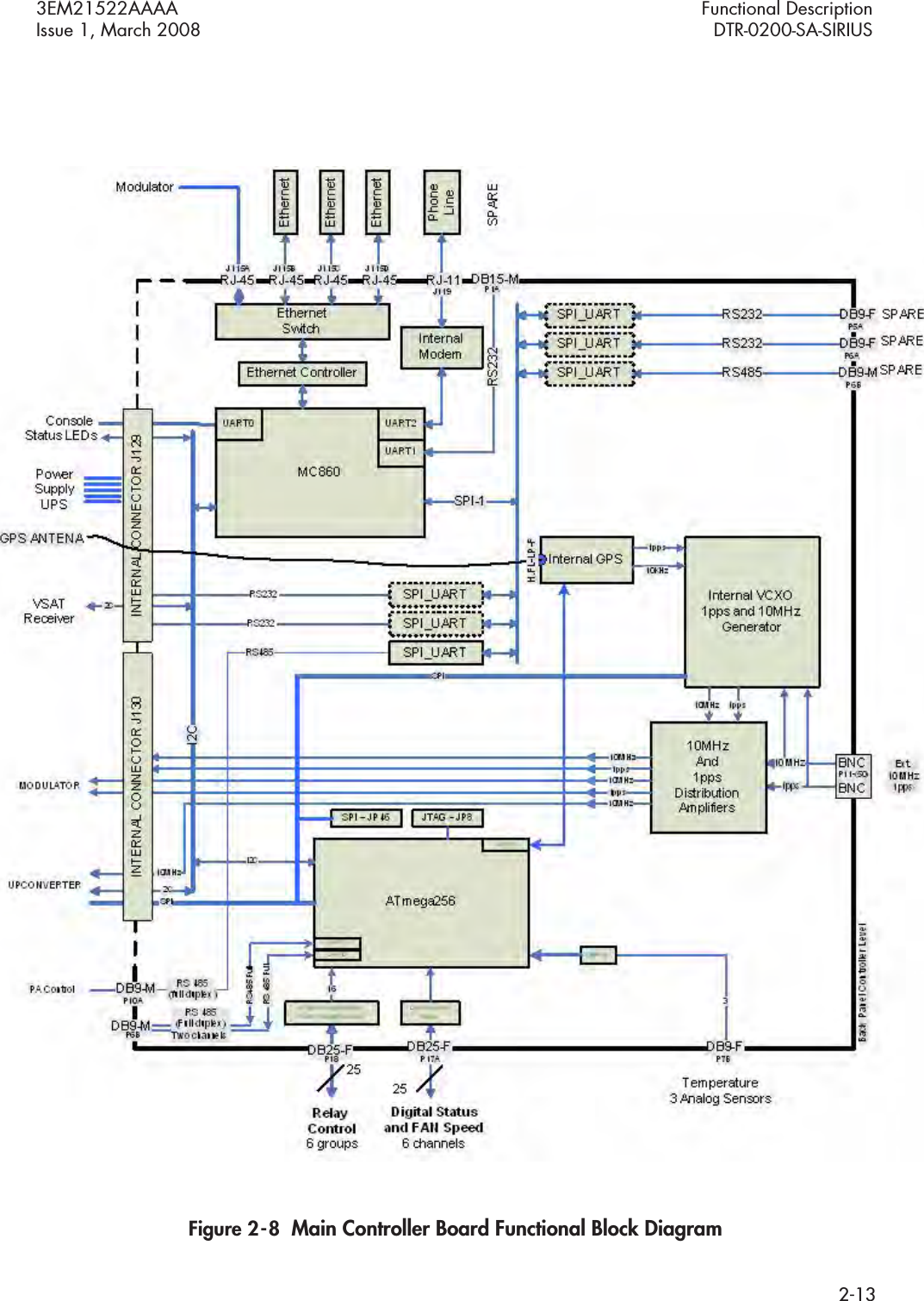
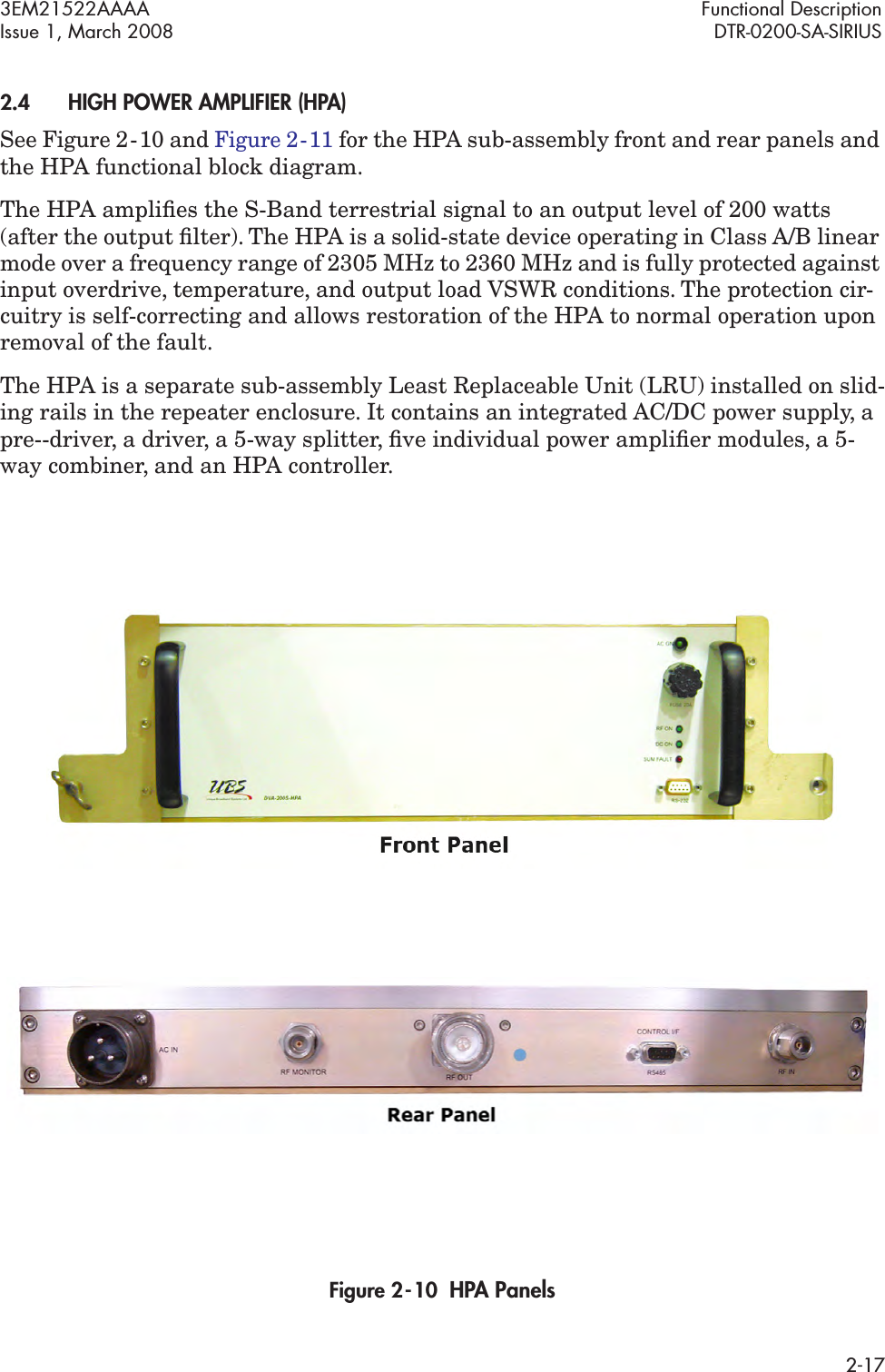
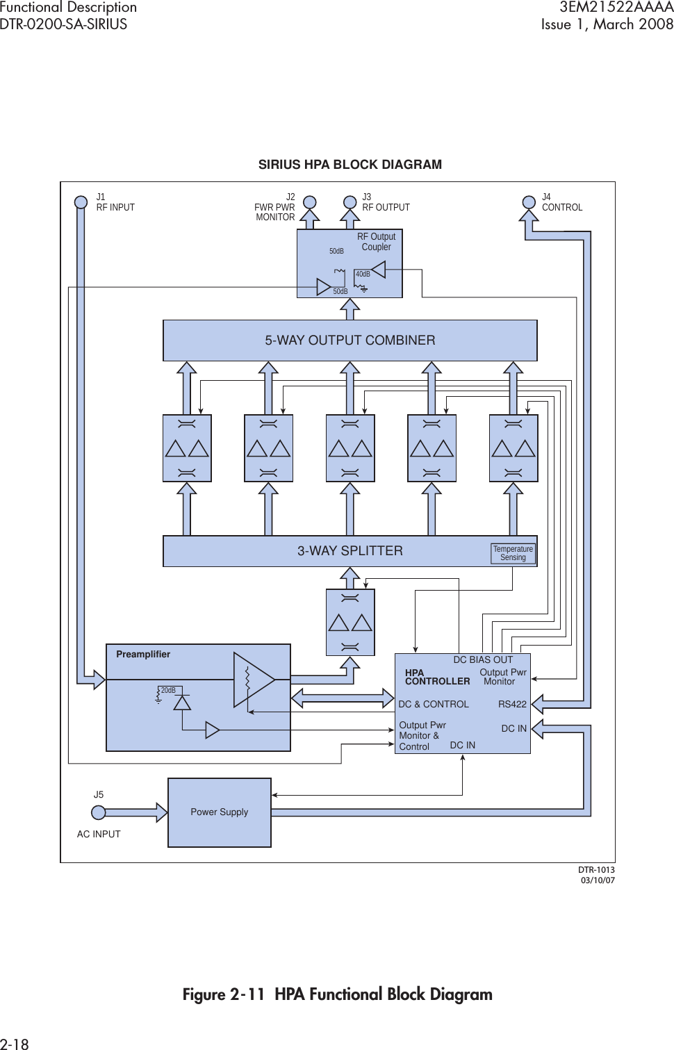
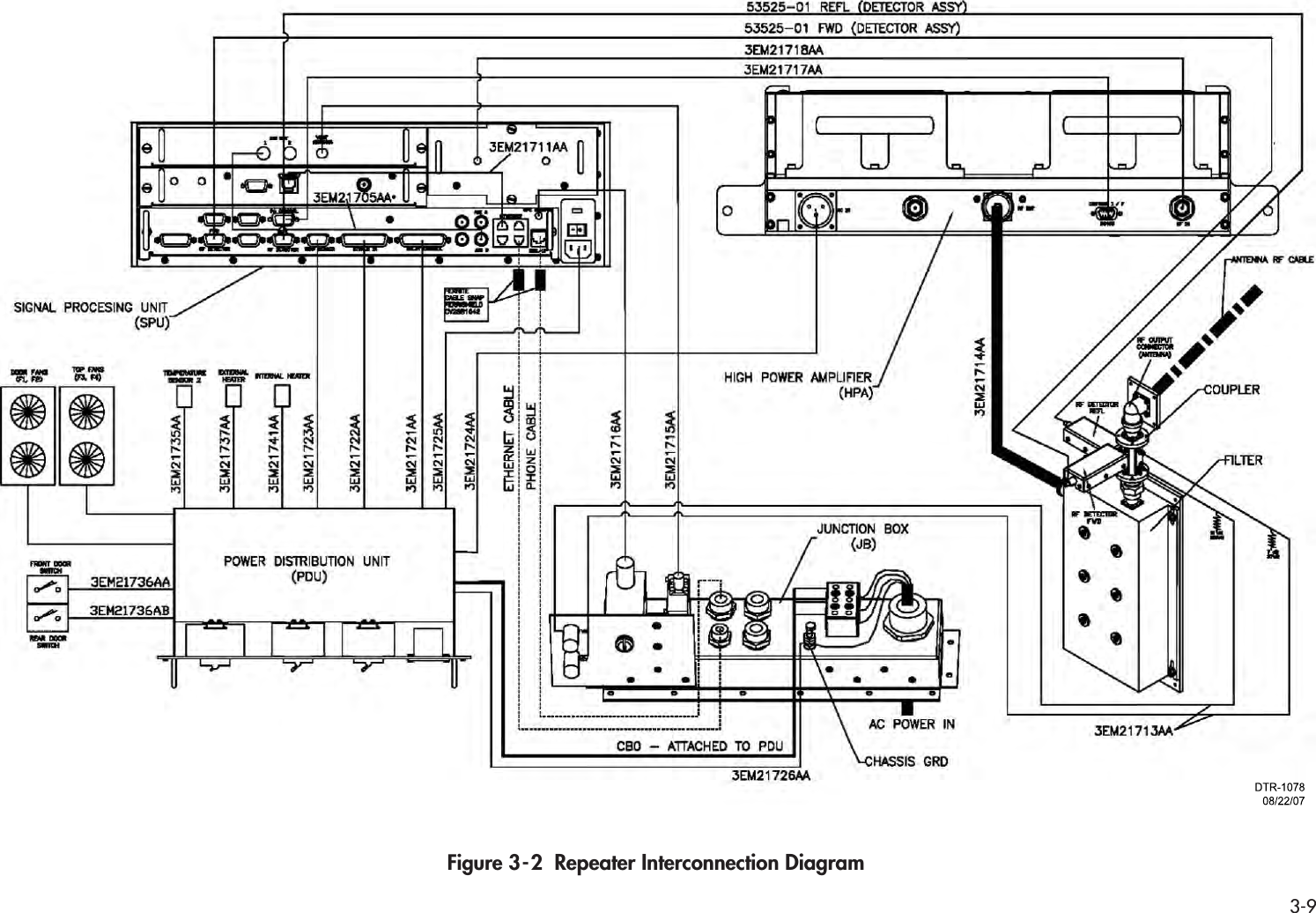
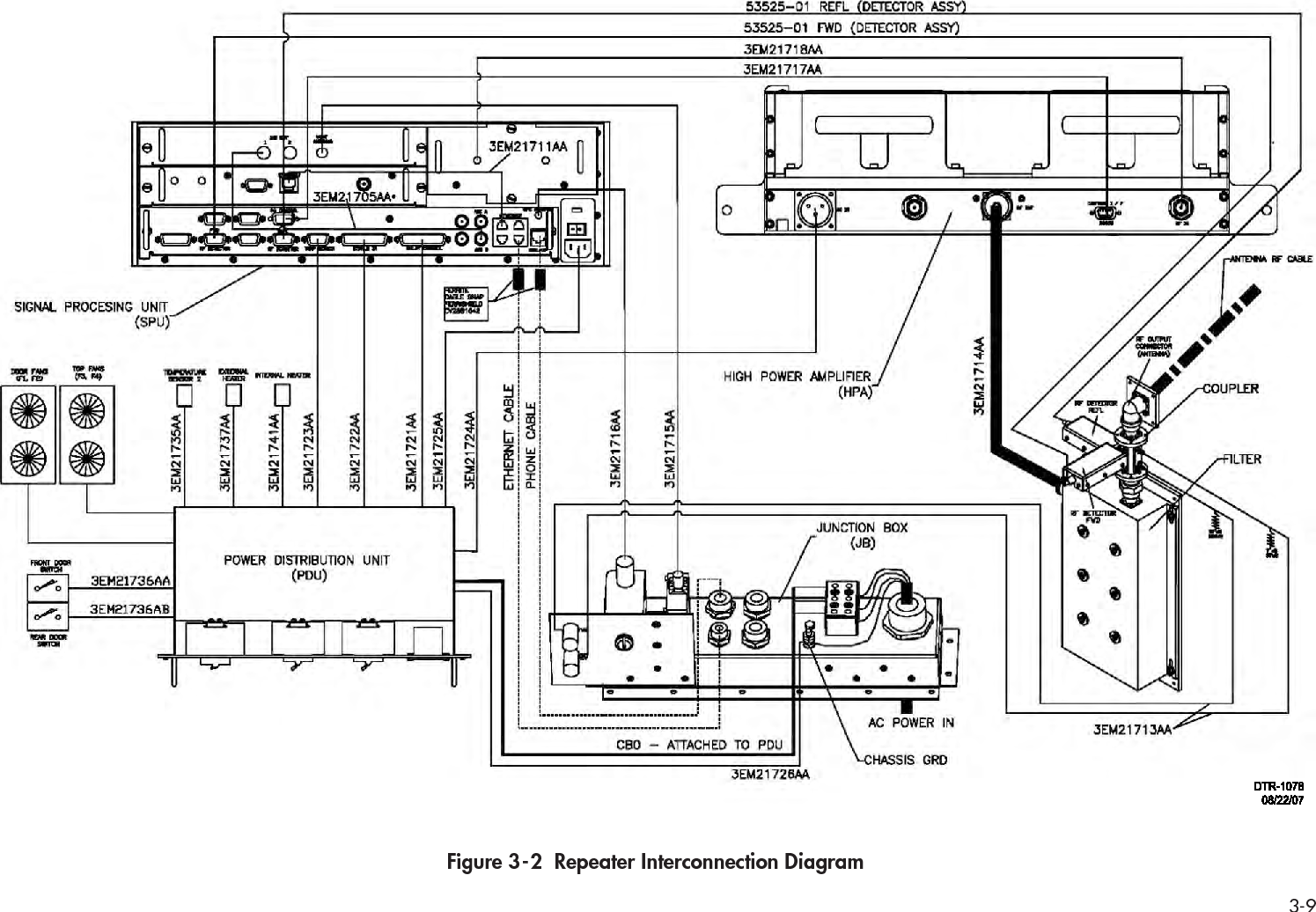
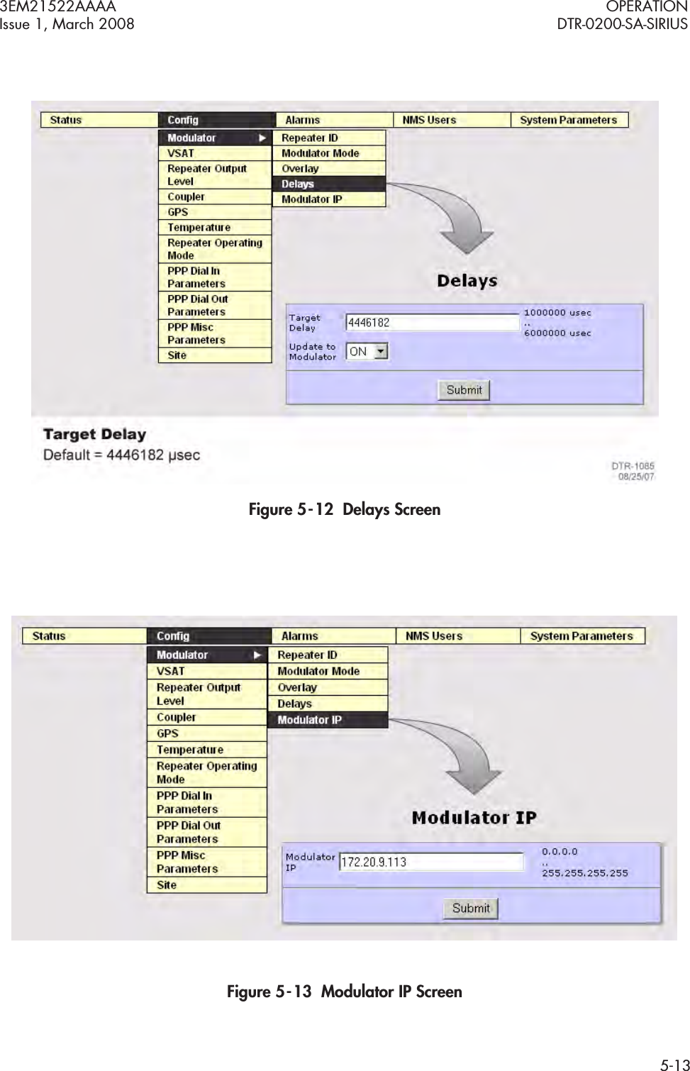
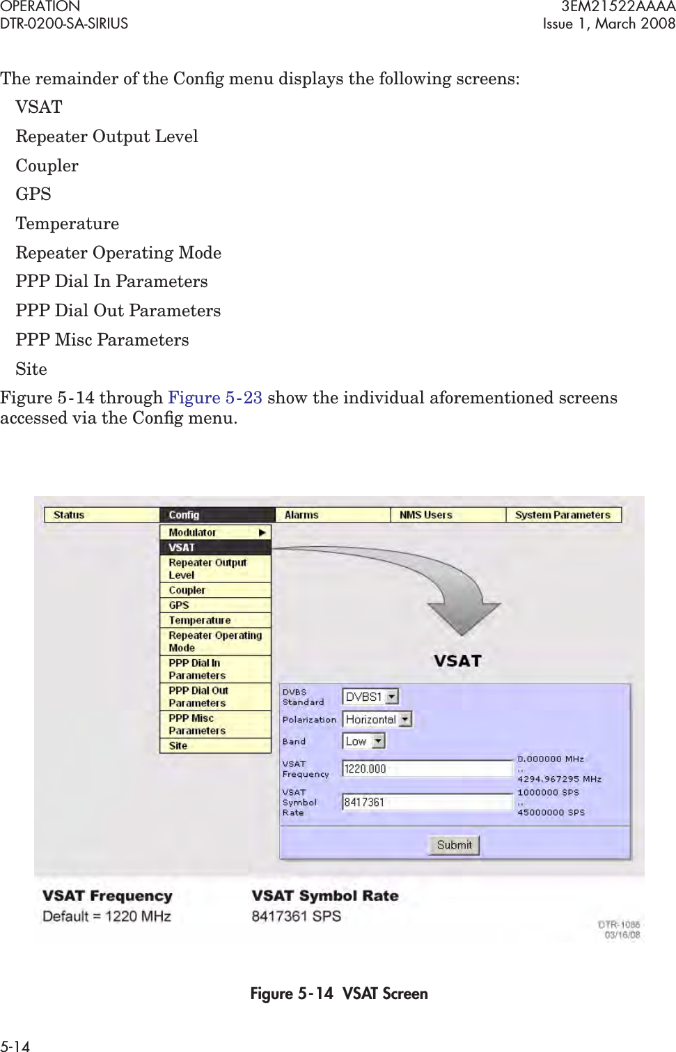
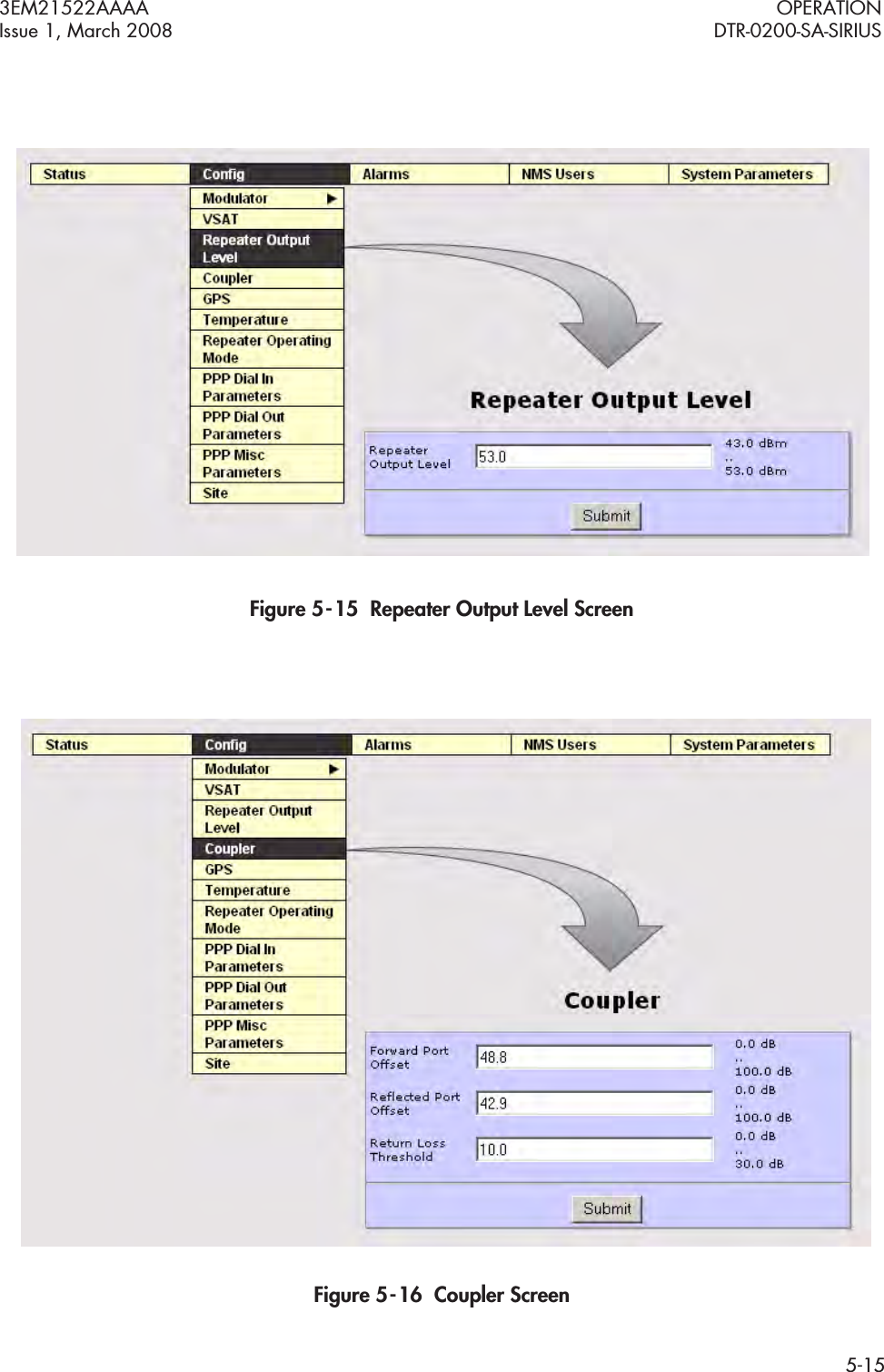
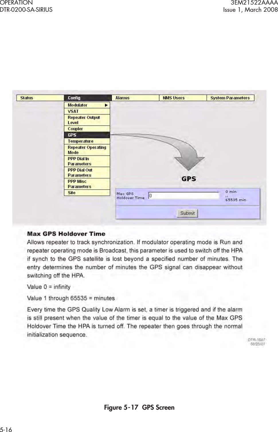
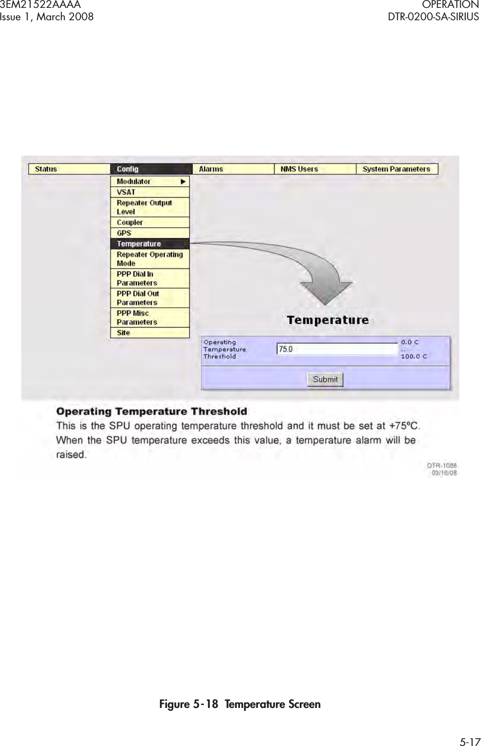
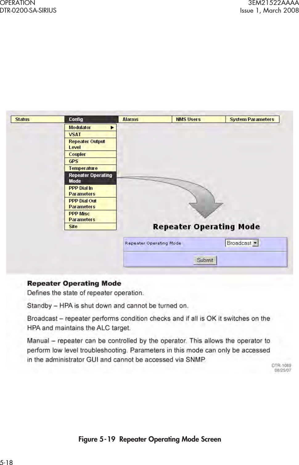
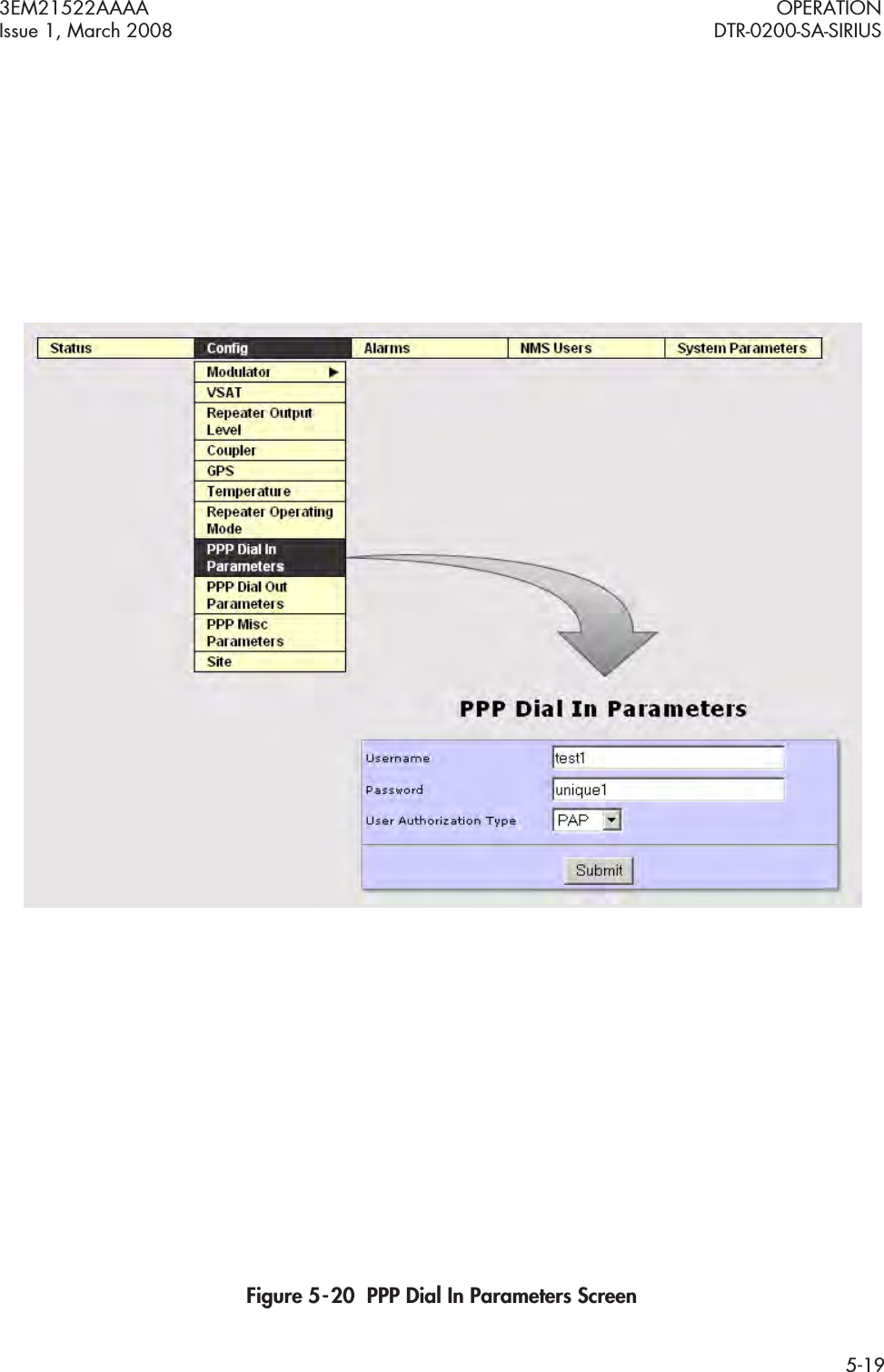
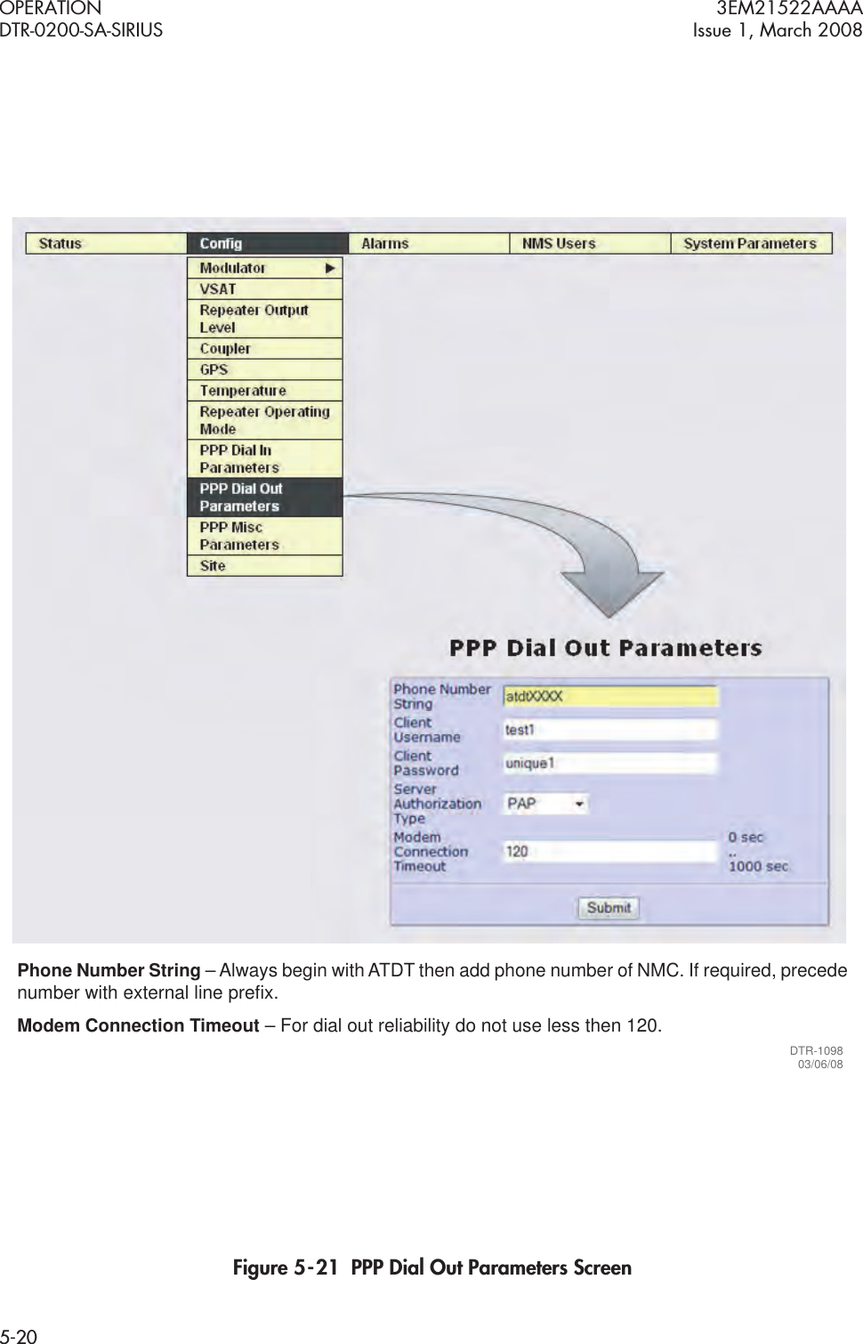
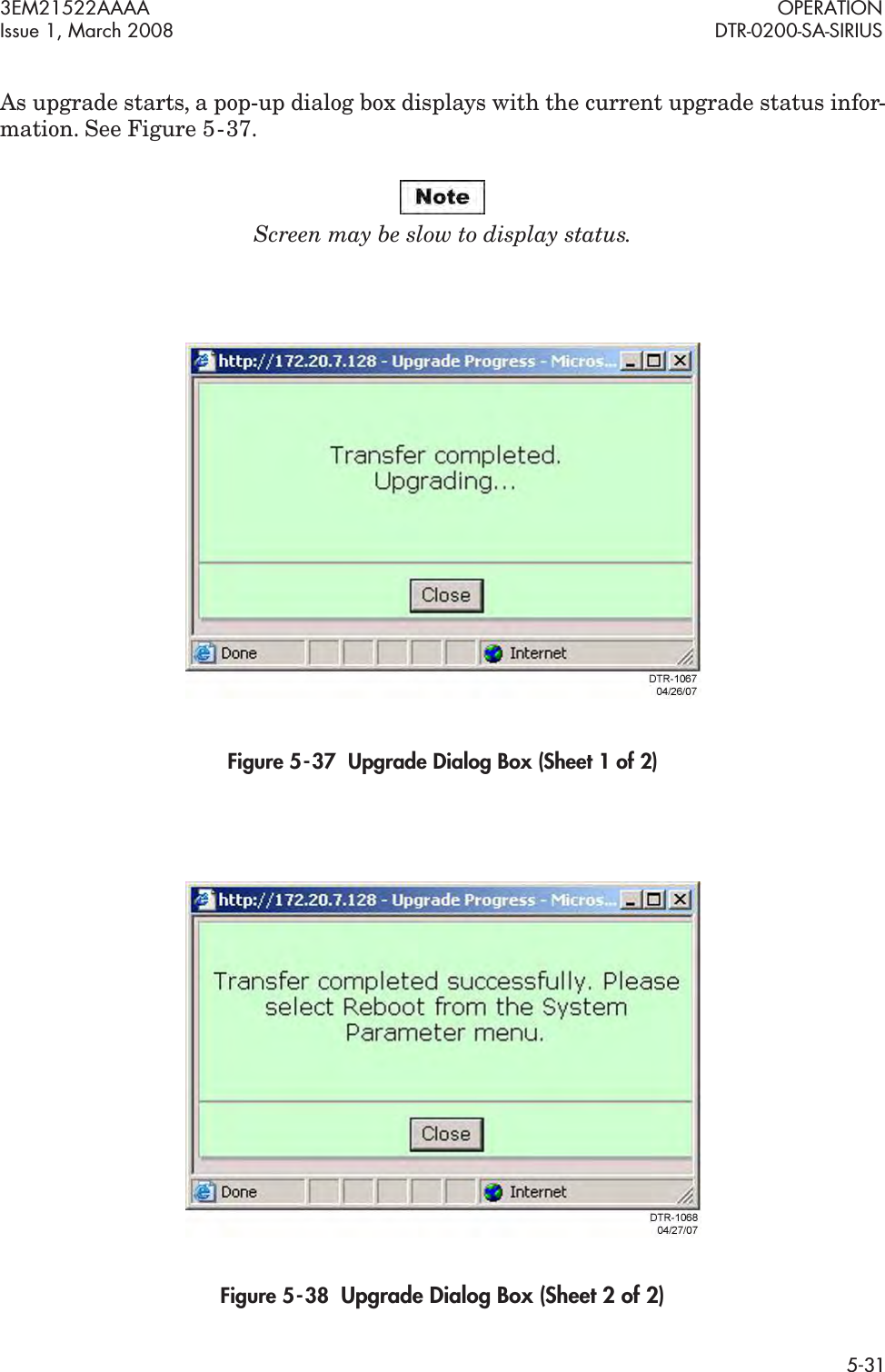
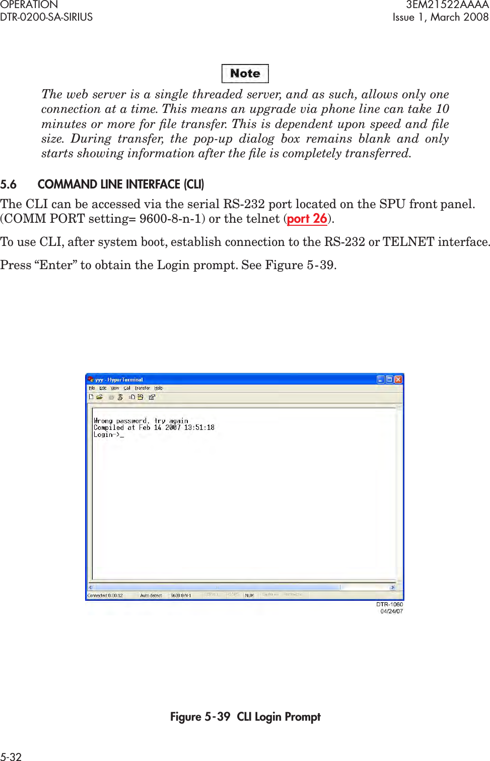
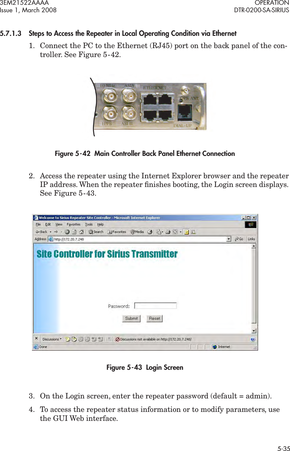
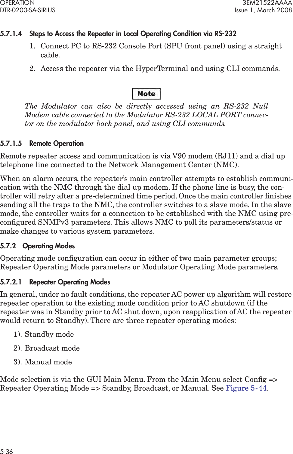
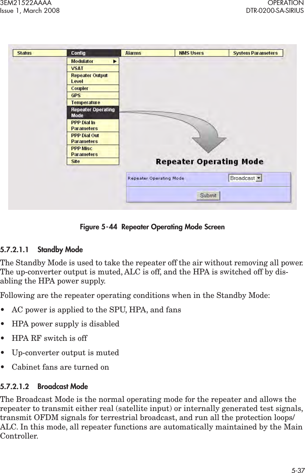
![OPERATION 3EM21522AAAADTR-0200-SA-SIRIUS Issue 1, March 20085-30Figure 5 - 35 System Parameters System Reset ScreenThe Upgrade screen allows the operator to upgrade system components by using the Browse button to select the proper upgrade file (e.g.; Main Controller, Supervisor Con-troller, VSAT Controller, Modulator [PPCO, PPCI, DSP, FPGA], Up-Converter, HPA). After file selection, click on “Start Download”. See Figure 5 - 36.Figure 5 - 36 System Parameters Upgrade Screen](https://usermanual.wiki/Sirius-XM-Radio/DTR0200.Users-Manual-Part-1/User-Guide-2178712-Page-96.png)