Sirius XM Radio DTR0200 ALU Repeater User Manual 00 DTR Iss 1
Sirius XM Radio Inc. ALU Repeater 00 DTR Iss 1
UserManual.wiki
>
Sirius XM Radio
>
DTR0200 User Manual
>
Users Manual Part 2
Contents
1.
Users Manual Part 1
2.
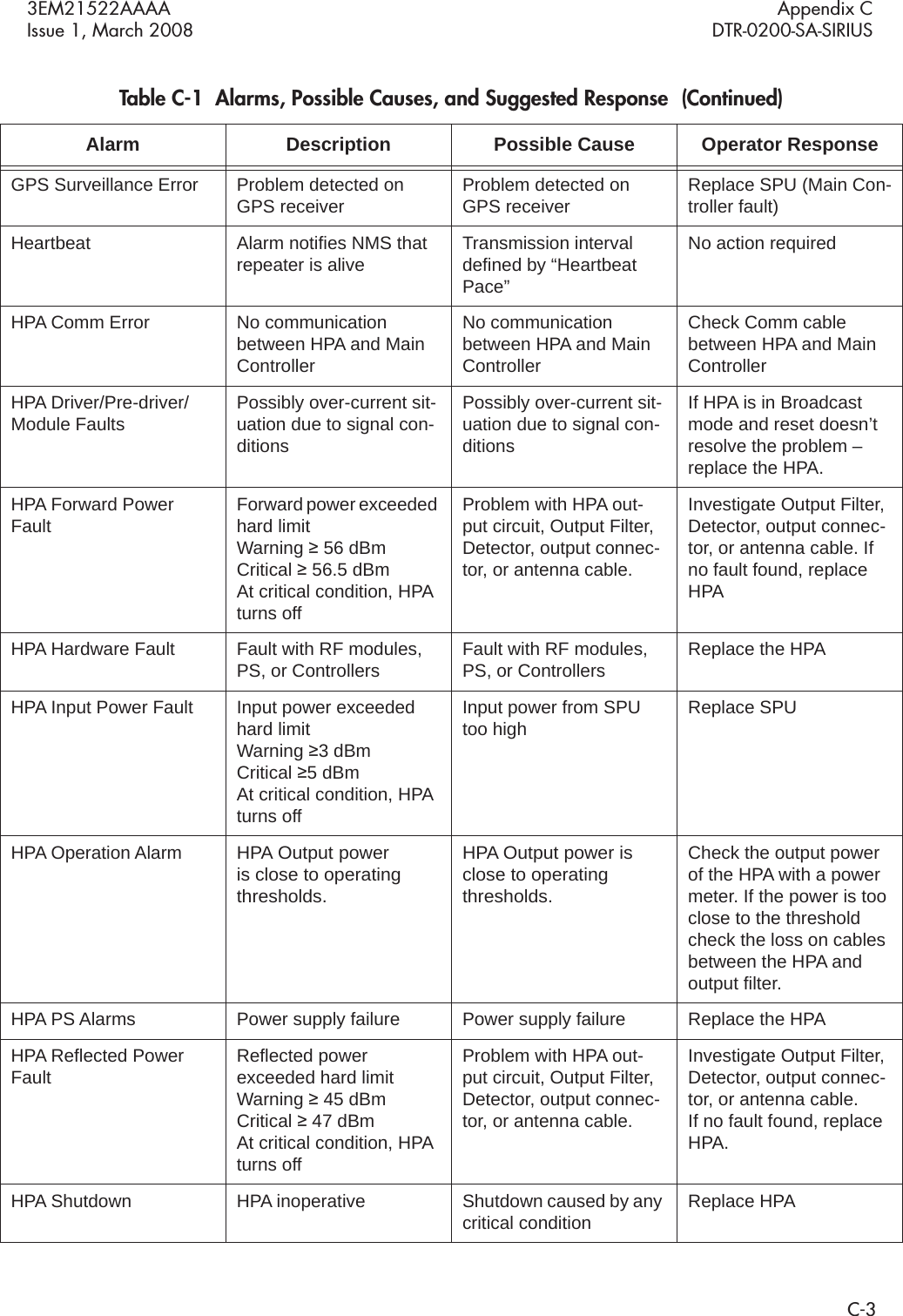
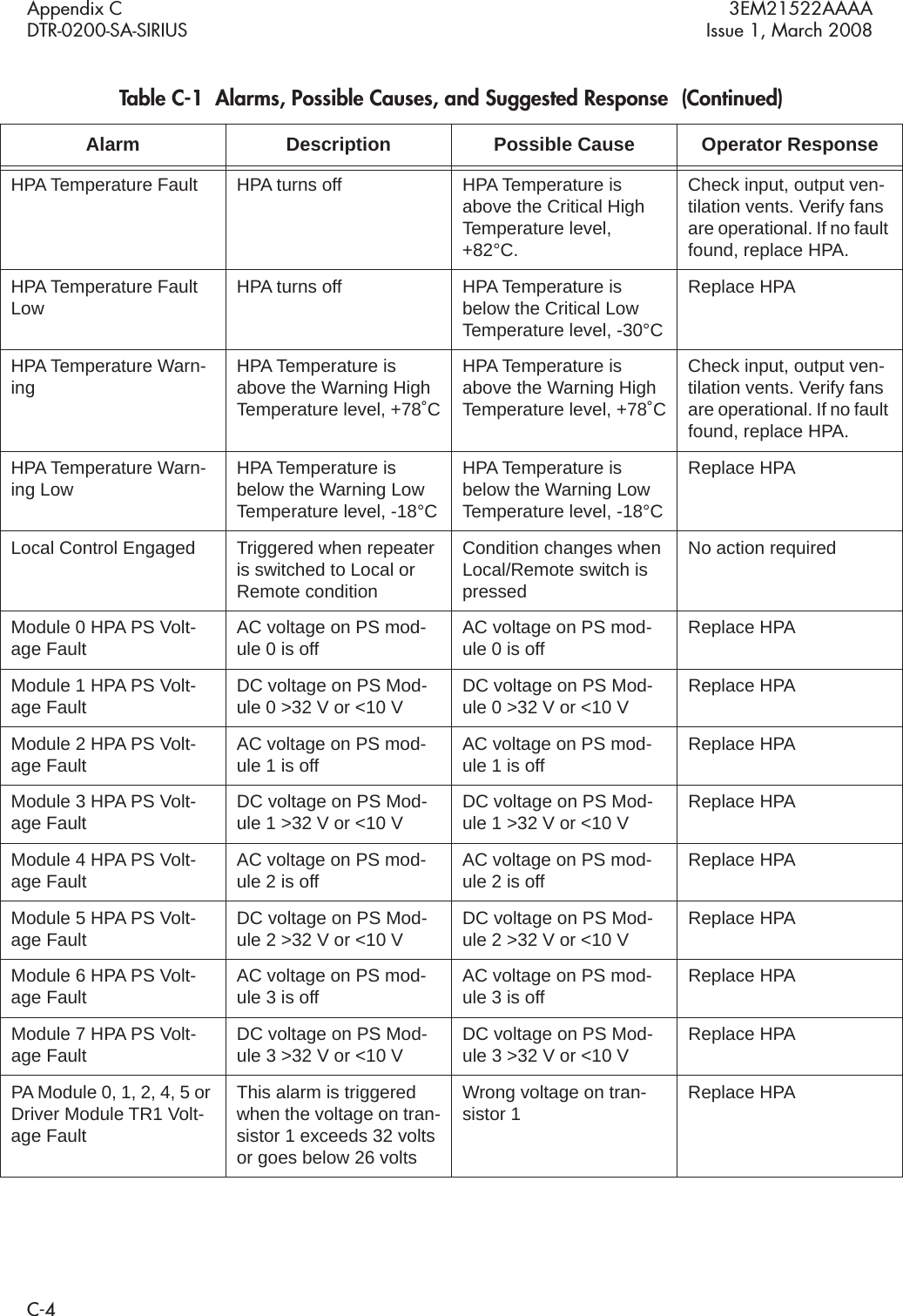
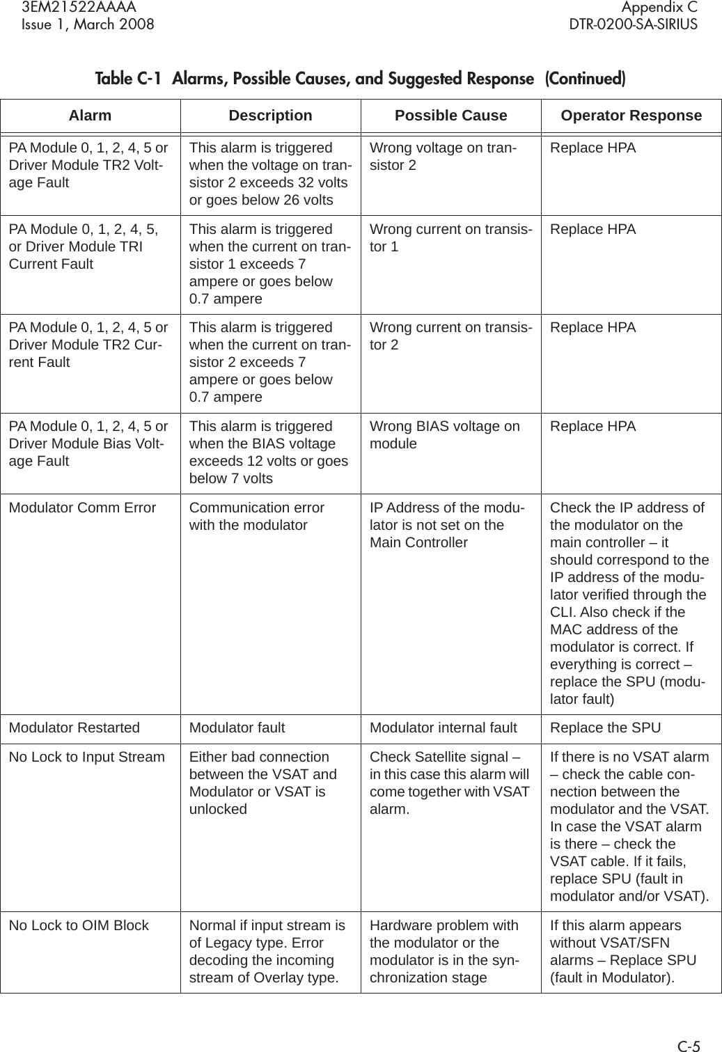
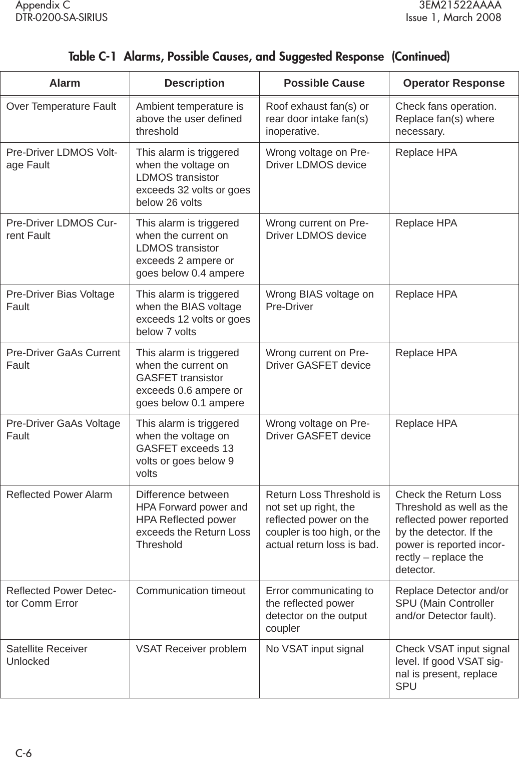
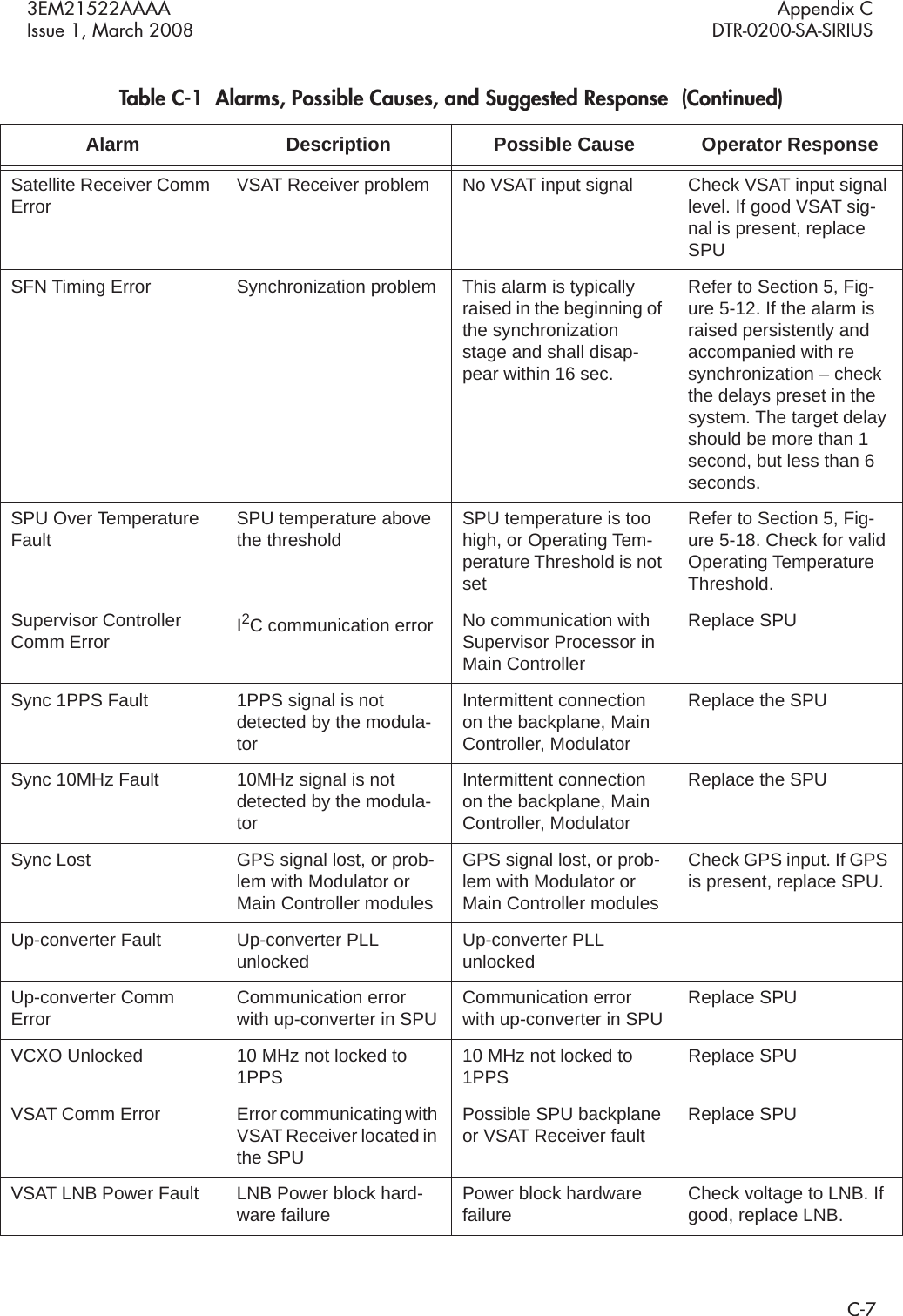
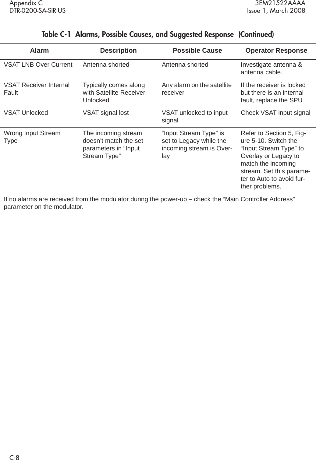
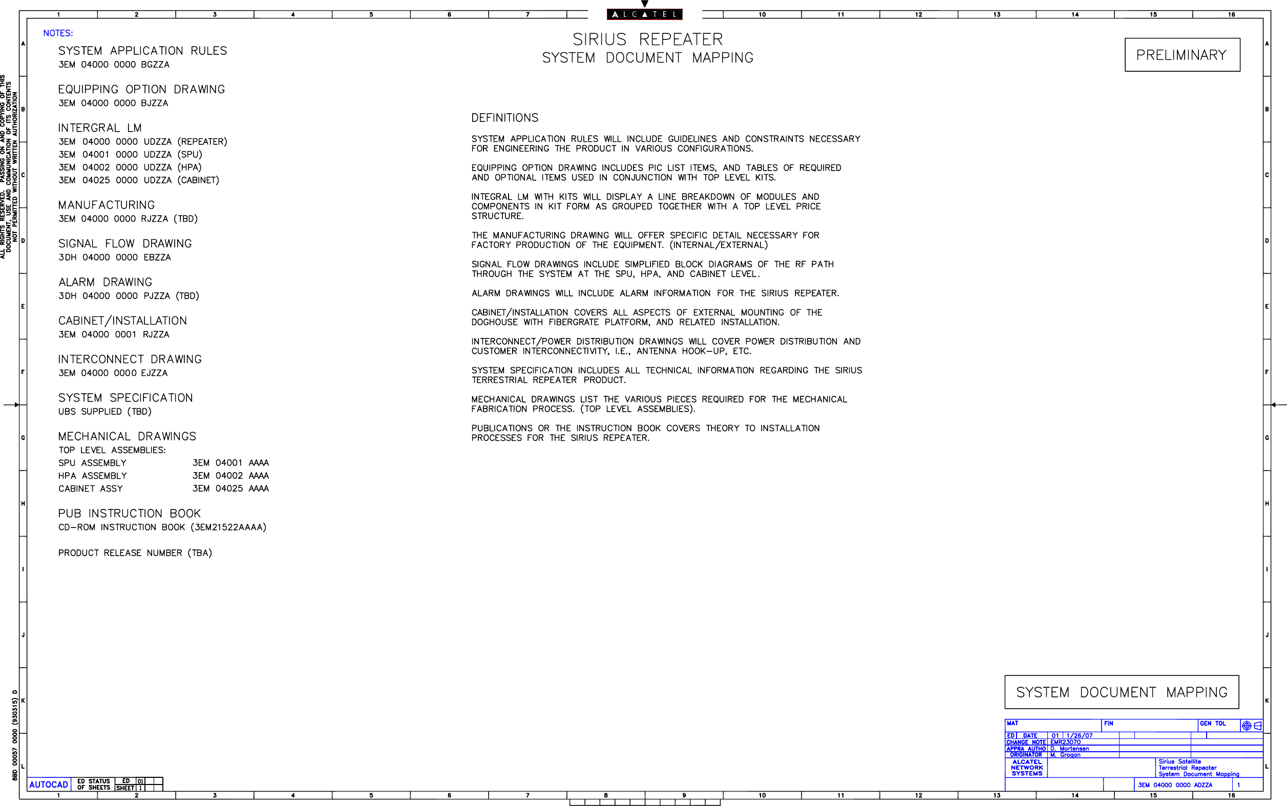
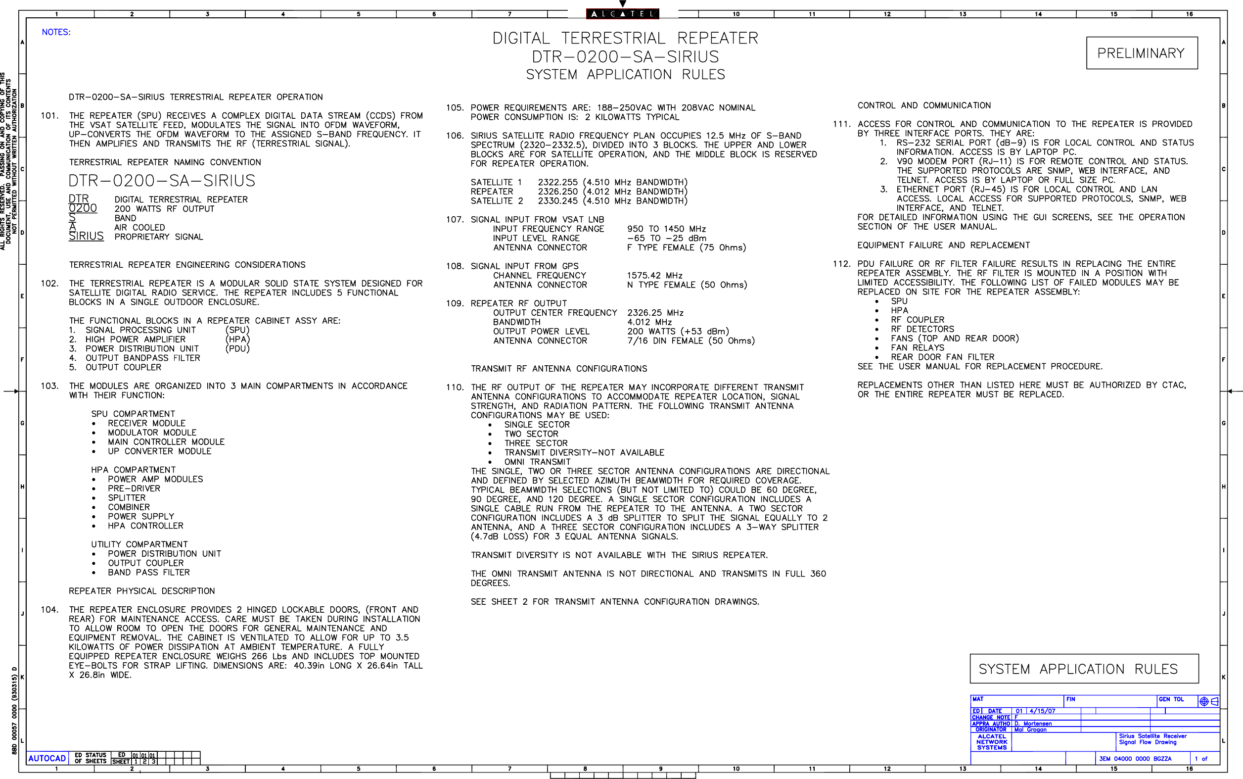
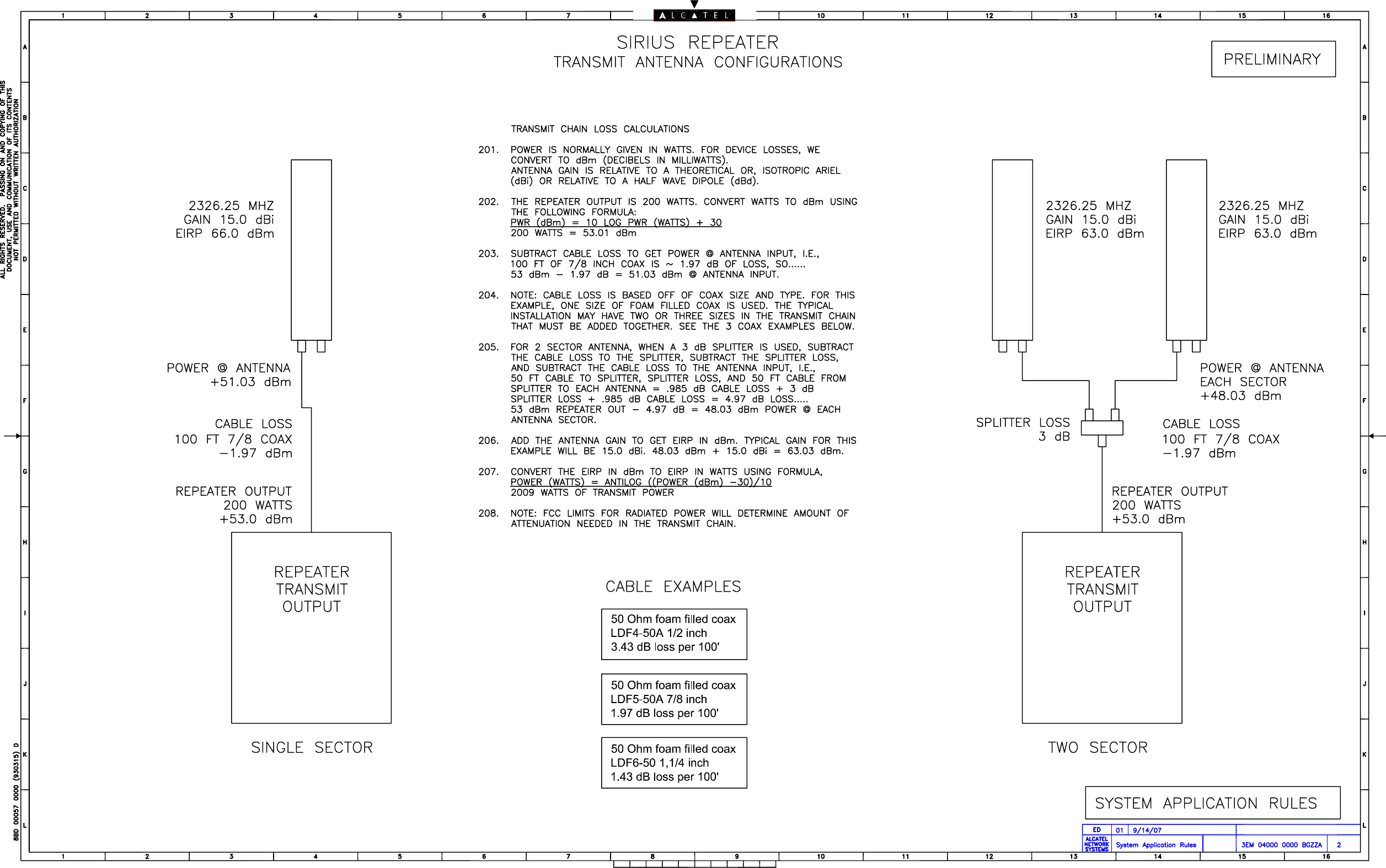
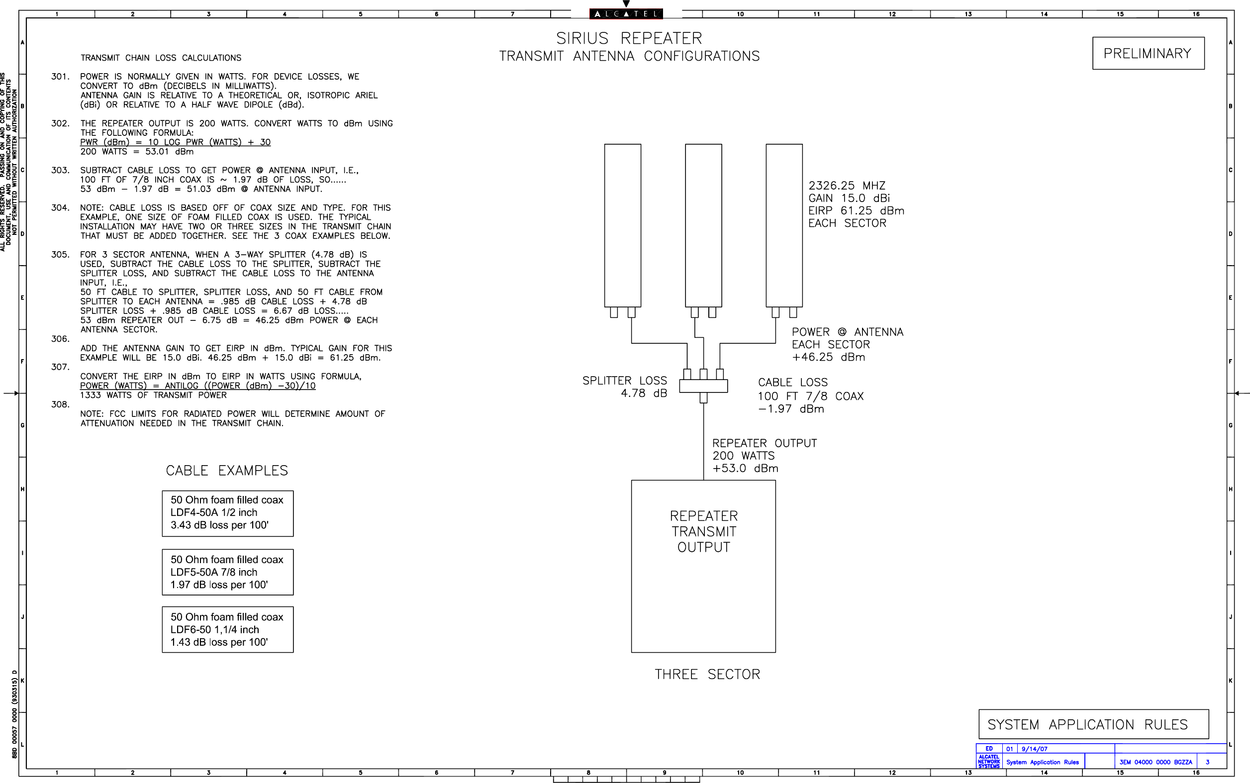
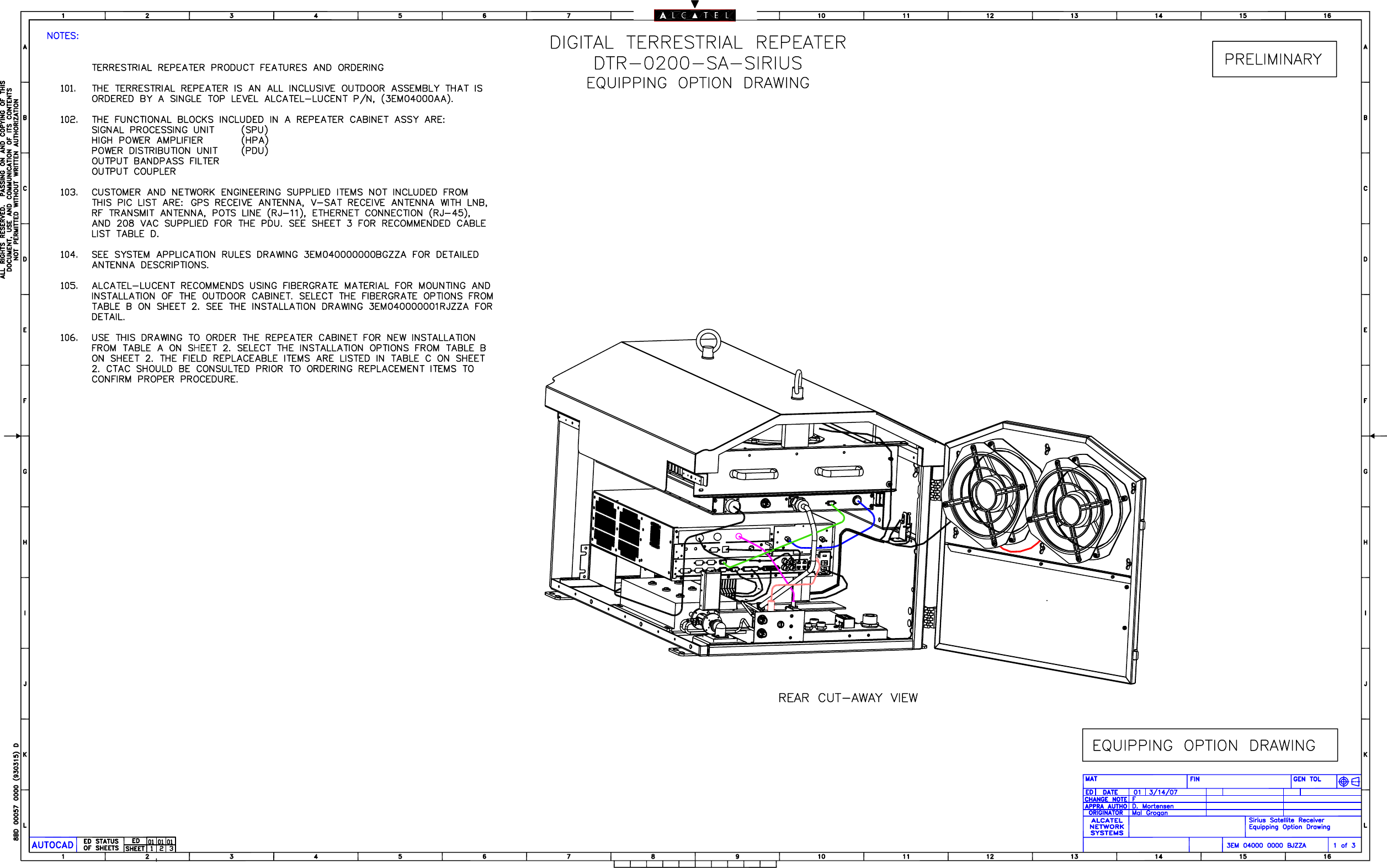
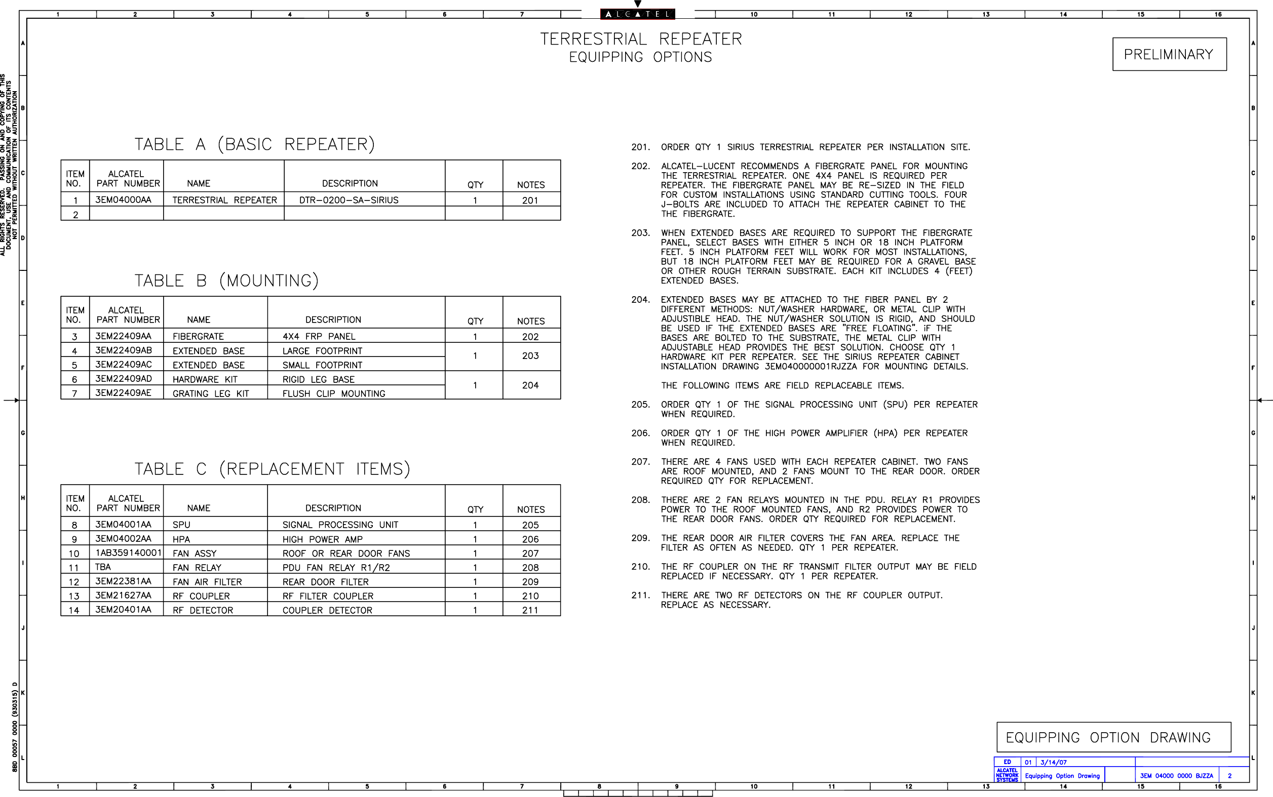
Users Manual Part 2
Users Manual Part 2
Navigation menu
Upload a User Manual
Namespaces
Wiki Guide
HTML
PDF
Info
Views
User Manual
Discussion / Help
Navigation