Sirius XM Radio DTR0200 ALU Repeater User Manual 00 DTR Iss 1
Sirius XM Radio Inc. ALU Repeater 00 DTR Iss 1
Contents
- 1. Users Manual Part 1
- 2. Users Manual Part 2
Users Manual Part 2
3EM21522AAAA Maintenance
Issue 1, March 2008 DTR-0200-SA-SIRIUS
6-1
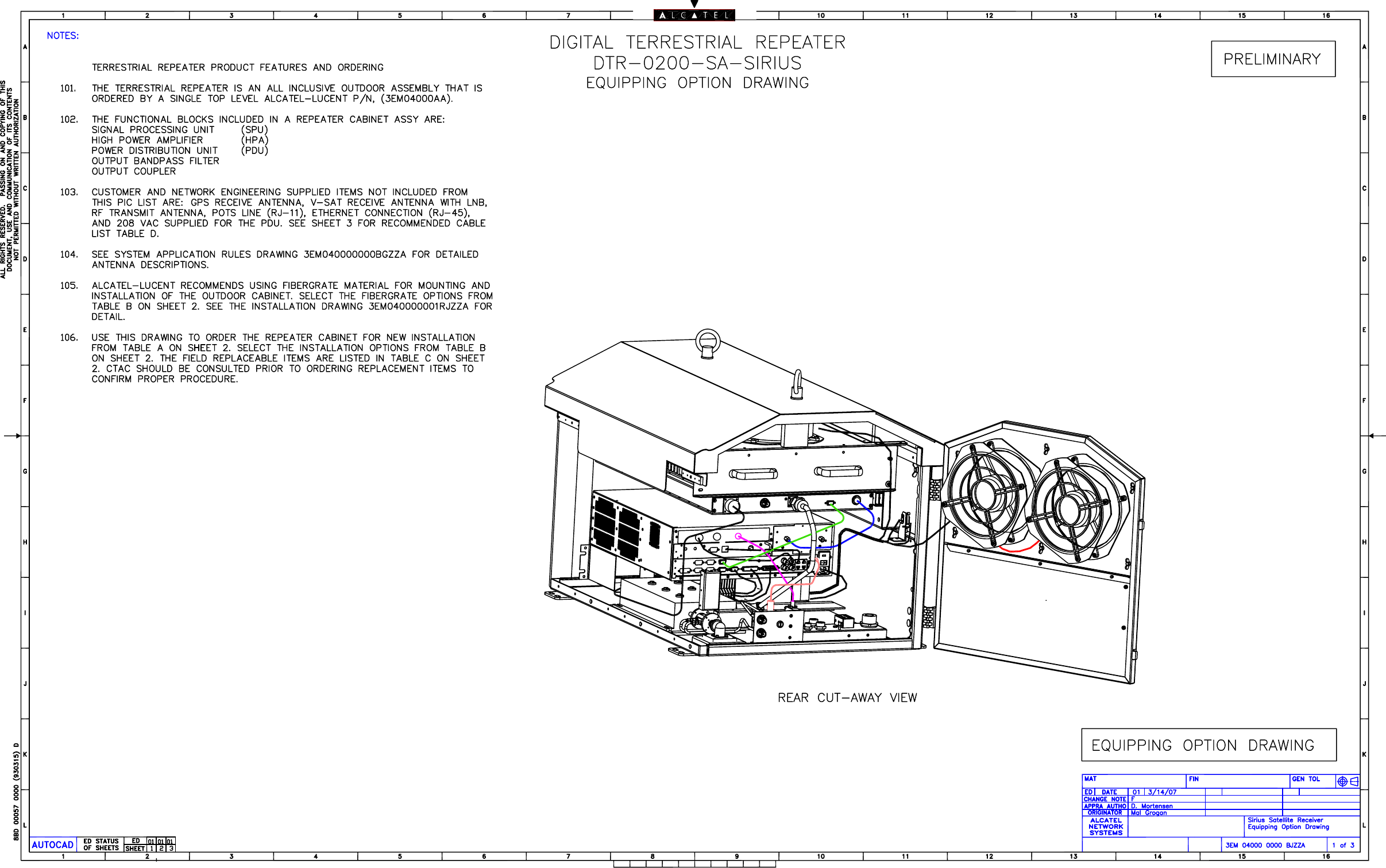
6 MAINTENANCE
6.1
GENERAL
This section addresses repeater faults, fault identification, fault troubleshooting,
removal and replacement of faulty item(s), and final system testing.
6.2
MAINTENANCE PHILOSOPHY
Repeater maintenance is limited to removal and replacement of least replaceable
units (SPU, HPA, RF Coupler, RF Detector(s) and fixed hardware components such as
air filter, fans, and cables) and modification of GUI screen parameters. The user is not
authorized to attempt repair of any LRU. Repair or replacement of any other compo-
nents, such as the PDU, Band Pass Filter, or internal heater requires replacement of
the entire repeater assembly
. Prior to shipping a repeater back to Alcatel-Lucent, con-
tact the Customer Technical Assistance Center (CTAC) to discuss the problem. See
CTAC contact instructions in the Front Matter section of this manual.
6.3
TEST EQUIPMENT
The only test equipment required is a PC.
6.4
SPECIAL TOOLS
Two special wrenches are required to perform maintenance on the HPA and the RF
Coupler.
•
HPA RF CONNECTOR WRENCH:
1 1/4-inch open-end, overall length not to exceed four inches. Maximum
thickness 1/2 inch.
•
RF COUPLER WRENCH:
1 1/8-inch open-end, overall length not to exceed five inches. Maximum
thickness 1/8 inch.
6.5
PREVENTIVE MAINTENANCE
The only required scheduled preventive maintenance is for the rear door air filter
assembly. As a general rule, it is recommended replacing the air filter every 6 months
under normal conditions or every 3 months in dusty environments. Under extremely
dusty conditions or in a windy environment near open areas with loose blowing sand/
dirt, it is recommended that filters be inspected more frequently and adjusting
replacement intervals as deemed necessary.
6.6
TROUBLESHOOTING OVERVIEW
Troubleshooting can be performed remotely and locally as described in the following
paragraphs.
6.6.1
Remote Troubleshooting Overview
Remote troubleshooting is performed at the NMC by an operator using the GUI screens.
When the cause of the fault is identified, the user determines if the fault can be cor-
rected from the NMC. If not, a maintenance technician is dispatched to the repeater site.

Maintenance 3EM21522AAAA
DTR-0200-SA-SIRIUS Issue 1, March 2008
6-2
6.6.2
Local Troubleshooting Overview
Local troubleshooting is performed at the repeater site by a dispatched technician
using a PC, GUI screens (or CLI), and external test equipment. When the fault is cor-
rected, the technician follows on with a system test. When satisfied that the repeater
is operating correctly
, coordination between the technician and the NMC operator
returns the repeater back to the remote operating condition and broadcast mode.
6.7
REPEATER ALARM INDICATORS
Alarms are indicated on GUI Status screens, GUI Alarms screens, and front panel
LEDs.
Refer to Appendix D, Alarm Descriptions, Causes, and Corrections
.
6.8
TROUBLESHOOTING PROCEDURES
6.8.1
Remote Troubleshooting/Repair Procedures
• Upon receipt of an alert via the repeater site TELCO line, NMC personnel
will evaluate the indicated problem(s). Refer to the Operations section for
instructions on use of the GUI.
• Access the GUI
• View the Alarms screens for indicated problem identification.
• View the Status screens for additional information.
• If it is determined that the problem(s) can be corrected remotely, access the
necessary GUI screens and correct as required.
• If it is determined that the problem(s) cannot be corrected from the NMC,
take the necessary steps to dispatch a technician to the repeater site to
perform local maintenance.
6.8.2
Local Troubleshooting/Repair Procedures
When indicated cautionary statements are adhered to by the technician during
maintenance, the equipment is unlikely to present a hazard to the technician or the
structure.
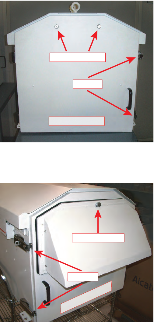
The front and rear doors of the repeater cabinet are secured by
draw latches and captive locking screws. There are two latches
and two locking screws on the cabinet front door and two latches
and one locking screw on the cabinet rear door (see figure 6-1). It is
imperative that opening and/or closing of these doors be done in
the provided sequence. Failure to follow the sequence could result
in door warping or bending and render the cabinet water protec-
tion system invalid.
WARNING
Possibility of
Damage
to Equipment
3EM21522AAAA Maintenance
Issue 1, March 2008 DTR-0200-SA-SIRIUS
6-3
Opening the Door – first release the captive locking screw(s) then
undo the draw latches.
Closing the Door – first secure the draw latches then tighten the
captive locking screw(s).
Figure 6 - 1 Locking Screws and Latches (Sheet 1 of 2)
Figure 6 - 1 Locking Screws and Latches (Sheet 2 of 2)
Locking Screws
Front Door
Latches
DTR-1092
10/28/07
Locking Screw
DTR-1093
10/28/07
Latches
Rear Door

Maintenance 3EM21522AAAA
DTR-0200-SA-SIRIUS Issue 1, March 2008
6-4
NMC coordination must be accomplished prior to repeater being
switched to Local operating condition. This will prevent conflict-
ing actions between the NMC and on-site operator(s) and preclude
possible personal injury and/or equipment damage.
• Switch the repeater to the Local operating condition.
• Connect the PC to a repeater Ethernet (LAN) connector on the back panel
of the Controller (or to the SPU front panel RS-232 connector for CLI if an
active LAN connector is not available).
• View the SPU front panel indicators.
• Access GUI (or CLI screens).
• Use the Alarms and Status
GUI
in conjunction with the SPU front panel
indications to help identify problem(s).
• Refer to Appendix D, “Alarm Descriptions, Causes, and Suggested
Responses”, for procedures to correct problems.
• Access the GUI screens and enter changes as required.
• Remove and replace components if required.
• Major unit replacement requires parameter updating.
• Run repeater test on completion of troubleshooting/repair.
• Coordinate with the NMC and return repeater to the Remote operating
condition.
When working in the vicinity of fans (under repeater roof or
replacing air filter on repeater back door), power to fans must be
removed.

3EM21522AAAA Maintenance
Issue 1, March 2008 DTR-0200-SA-SIRIUS
6-5
POSSIBILITY OF EQUIPMENT AND/OR STRUCTURE DAM-
AGE DUE TO FIRE. Any fuse replacement must be with an
exact fuse value (size, rating, capacity) as the fuse being
replaced.
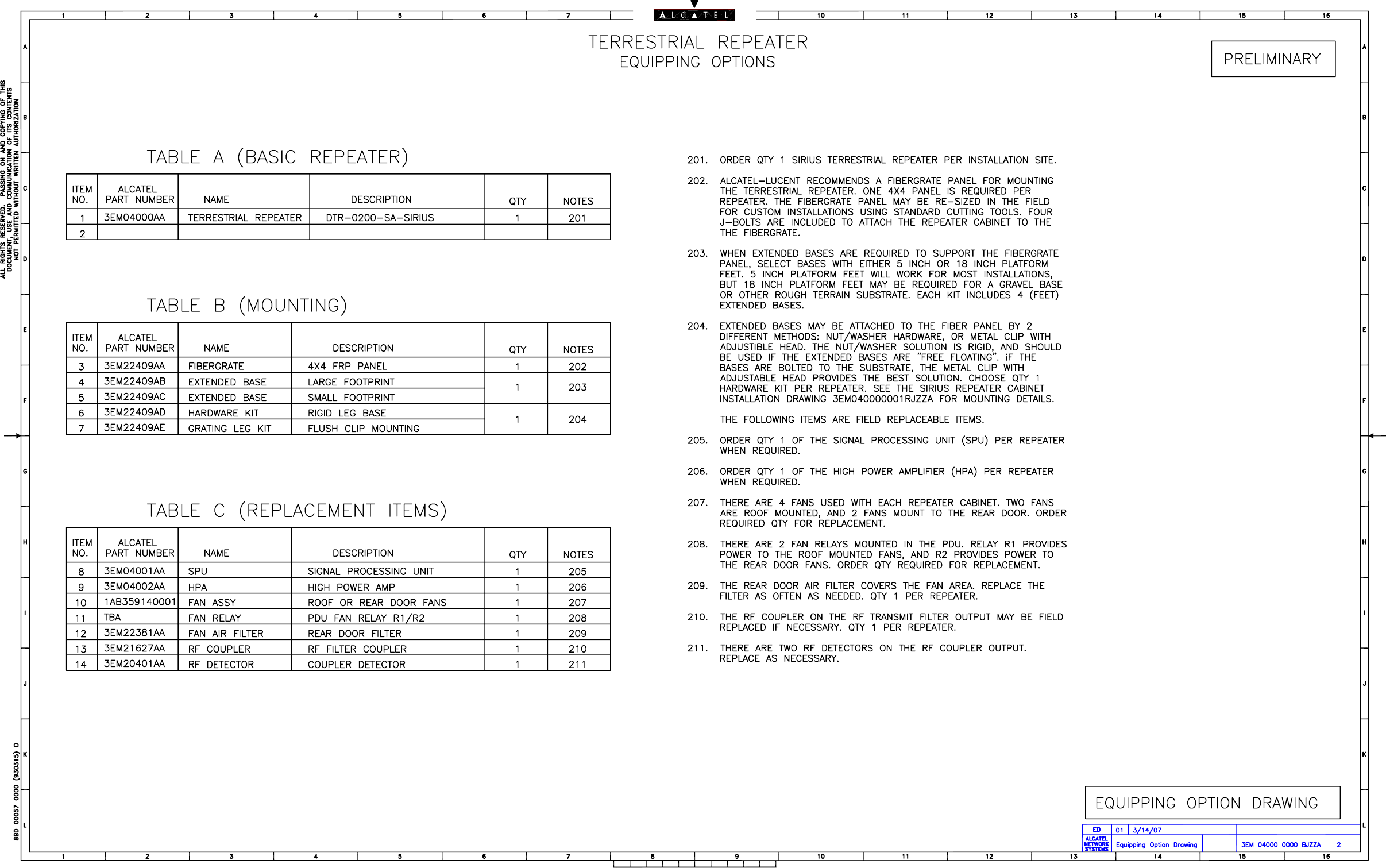
6.9
REMOVAL AND REPLACEMENT (R/R) PROCEDURES
Table 6-1 Remove/Replace Matrix
UNIT PROCEDURE
Signal Processing Unit (SPU) Refer to Chart 1
High Power Amplifier (HPA) Refer to Chart 2
RF Detectors Refer to Chart 3
RF Coupler Refer to Chart 4
Rear Door Intake Fans 1 & 2 Refer to Chart 5
Under Roof Exhaust Fans 3 & 4 Refer to Chart 6
Fan Relays R1/R2 Refer to Chart 7
Rear Door Air Filter Refer to Chart 8
PDU Front Access Circuit Breakers Refer to Chart 9
Power Distribution Unit (PDU) Replace Repeater
Band Pass Filter Replace Repeater
Internal Heater Replace Repeater
WARNING
Possibility of
Damage
to Equipment
6-6 This page intentionally left blank.

3EM21522AAAA Maintenance
Issue 1, March 2008 DTR-0200-SA-SIRIUS
6-7
Chart 1 Remove and Replace signal Processing Unit (SPU)
Main power to repeater must be off.
STEP PROCEDURE
REMOVAL
1Open front and rear doors
a To open front door
Release two locking screws then release two door latches.
bTo open rear door
Release one locking screw then release two door latches
2Coordinate with NMC and switch repeater to local operating condition.
3Switch all repeater PDU circuit breakers to OFF switching main
breaker last
4Switch OFF commercial power source breaker supplying power to
repeater.
5Hang “DANGER – DO NOT TURN ON – PERSONNEL WORKING” sign at
commercial power source breaker.
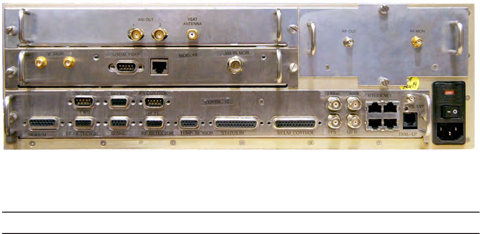
6See
Figure 6 - 2
for SPU rear cable connector panels (VSAT rcvr,
modulator, controller, and up–converter) and disconnect all cables. Be
sure to mark cables for ease in reconnecting.
7Remove SPU via front of cabinet.
Maintenance 3EM21522AAAA
DTR-0200-SA-SIRIUS Issue 1, March 2008
6-8
Figure 6 - 2 SPU Rear Connector Panels
STEP PROCEDURE CONT.
REPLACEMENT
8Insert new SPU into cabinet.
9Reconnect all cables.
10 Switch ON commercial power source breaker and remove danger sign.
11 Switch ON main PDU circuit breaker.
12 Switch ON remaining PDU circuit breaker.
13 Perform parameter changes.
When the SPU is replaced, various parameters must be changed. The
following steps identify the required parameter changes. The steps are
described using the GUI screens but the changes can also be made
using the CLI screens.
aCONFIG
• CONFIG>Modulator>Repeater ID
• CONFIG>Coupler
(enter the Forward and Reflected Port Offset values. These val-
ues are on labels affixed to the RF Detectors).
• CONFIG>PPP Parameters (Dial-in, Dial-out, Misc.).
(these values are obtained from the SIRIUS Network Manager).
• CONFIG>Site
(this information is furnished by the SIRIUS network Manager).

3EM21522AAAA Maintenance
Issue 1, March 2008 DTR-0200-SA-SIRIUS
6-9
STEP PROCEDURE CONT.
bALARMS
• ALARMS>Alarm Properties
(set SIRIUS specified alarm traps ON or OFF for NMS alerting).
cNMS USERS
• NMS USERS>User Properties
Auth Type = SHA
Priv Type = DES.
dSYSTEM PARAMETERS
• SYSTEM PARAMETERS>Network Parameters
(reset per SIRIUS network manager information).
• SYSTEM PARAMETERS>SNMP Parameters
(set SNMP Traps to ON and enter SNMP server IP address).
• SYSTEM PARAMETERS>Heartbeat Time
(set time for minimum NMC interference; Heartbeat will display
on Alarms Log).
• SYSTEM PARAMETERS>System Reset
At completion of System Parameters changes, perform System
Reset to allow changes to take effect.
eCONFIG
• CONFIG>Repeater Operating Mode
(set operating mode to Broadcast).
14 Perform repeater operational test as described in the Turn-Up section
of this manual.
15 Coordinate with NMC and return repeater to remote operating
condition.
a To Close Front Door
Secure two door latches then tighten two locking screws.
bTo Close Rear Door
Secure two door latches then tighten one locking screw.
6-10 This page intentionally left blank.

3EM21522AAAA Maintenance
Issue 1, March 2008 DTR-0200-SA-SIRIUS
6-11
Chart 2 Remove and Replace High Power Amplifier (HPA)
Main power to repeater must be off.
This procedure requires a 1 1/4” open end wrench with an overall length of
no more than 4 inches to disconnect and reconnect the RF OUT cable.
STEP PROCEDURE
REMOVAL
1Open front and rear doors.
a To open front door
Release two locking screws then release two door latches.
bTo open rear door
Release one locking screw then release two door latches.
2Coordinate with NMC and switch repeater to local operating condition.
3Switch all repeater PDU circuit breakers to OFF, switching main
breaker last.
4Switch OFF commercial power source breaker supplying power to
repeater.
5Hang “DANGER – DO NOT TURN ON – PERSONNEL WORKING” sign at
commercial power source breaker.
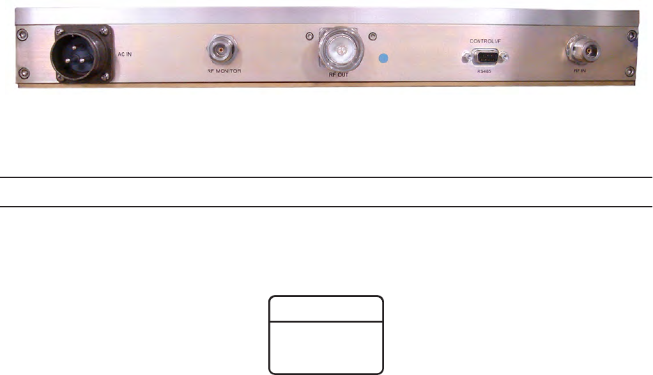
6See
Figure 6 - 3
for HPA rear panel cable connectors and disconnect HPA
cables (AC IN, RF OOUT, CONTROL I/F, RF IN). Be sure to mark
cables for proper reconnecting.
7Remove HPA via front of cabinet.
Maintenance 3EM21522AAAA
DTR-0200-SA-SIRIUS Issue 1, March 2008
6-12
Figure 6 - 3 HPA Rear Panel Connectors
STEP PROCEDURE CONT.
REPLACEMENT
8Insert new HPA into cabinet.
RF Connector must be installed properly to prevent RF leak-
age and/or arcing.
9Reconnect all cables (use 1 1/4” open-end wrench on RF OUT cable
connector).
10 Switch ON commercial power source breaker and remove danger sign.
11 Switch ON main PDU circuit breaker.
12 Switch ON remaining PDU circuit breakers.
13 Access GUI Global Status screen and check all values.
14 set repeater operating mode to Broadcast.
15 Coordinate with NMC and return repeater to Remote operating
condition.
16 Close front and rear doors.
a To close front door
Secure two door latches then tighten two locking screws.
bTo close rear door
Secure two door latches then tighten one locking screw.
WARNING
Possibility of
Damage
to Equipment
3EM21522AAAA Maintenance
Issue 1, March 2008 DTR-0200-SA-SIRIUS
6-13
Chart 3 Remove and Replace RF Detector(s)
Main power to repeater must be off.
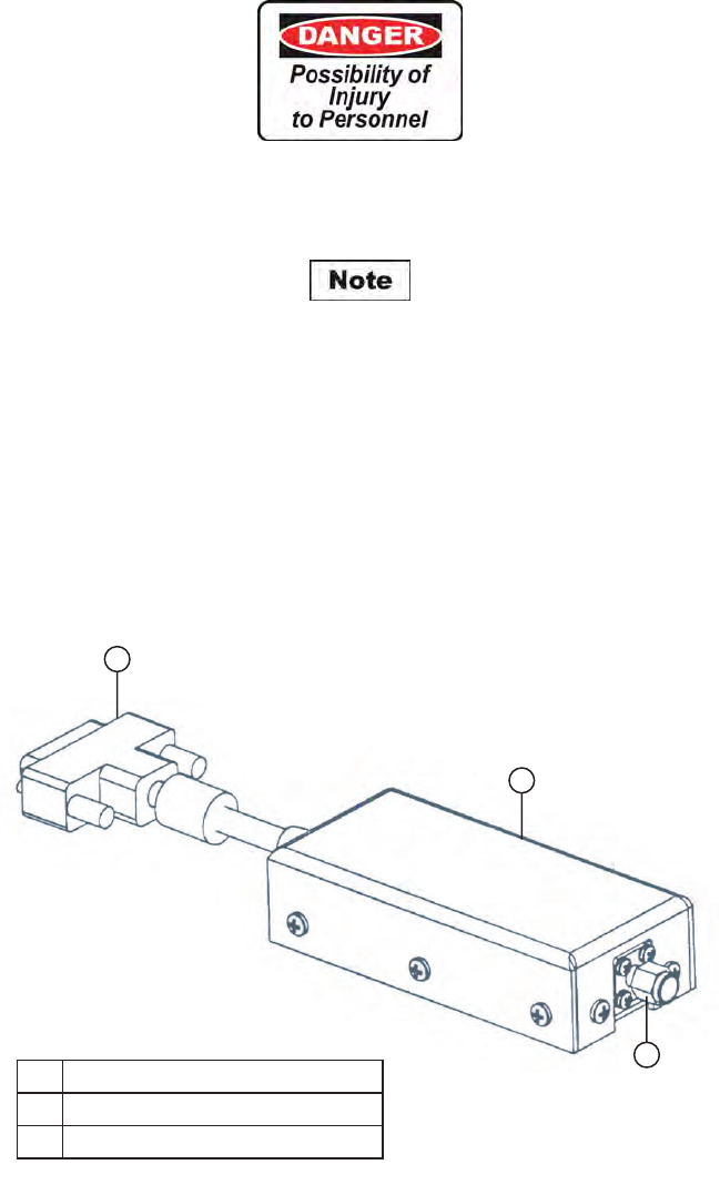
Prior to removal of detector(s), tag each to identify which is the forward RF
detector and which is the reflected RF detector. Failure to install detectors
correctly will cause the wrong feedback signals to be transmitted to the
main controller. This in turn will cause HPA power problems and inaccu-
rate power readings.
Figure 6 - 4 RF Detector
1
2
3
DTR-1045
07/17/07
1 DB-9 Connector to SPU Controller
2 RF Detector
3 SMA Connector to RF Coupler
Maintenance 3EM21522AAAA
DTR-0200-SA-SIRIUS Issue 1, March 2008
6-14
STEP PROCEDURE
REMOVAL
1Open front and rear doors.
a To Open Front Door
Release two locking screws then release two door latches
bTo Open Rear Door
Release one locking screw then release two door latches.
2Coordinate with NMC and switch repeater to Local operating condition.
3Switch OFF all repeater PDU circuit breakers, switching repeater main
breaker last.
4Switch OFF commercial power source breaker supplying power to
repeater.
5Hang “DANGER – DO NOT TURN ON – PERSONNEL WORKING” sign at
commercial power source breaker.
Before removing RF detectors, tag each as FWD or REFL. The vertical detec-
tor is the FWD and the horizontal detector is the REFL. If the detectors are
not connected properly during reinstallation, the RF power feedback signals
to the main controller will be incorrect.
6Loosen SMA connector(s) on detector(s) and remove detector(s) from RF
coupler.
7Disconnect detector cable connector(s) from SPU controller rear panel
(FWD RF DETECTOR, REF RF DETECTOR).
8Remove detector(s) from repeater.

3EM21522AAAA Maintenance
Issue 1, March 2008 DTR-0200-SA-SIRIUS
6-15
STEP PROCEDURE CONT.
REPLACEMENT
9Connect detector cable(s) to SPU controller rear panel (FWD RF
DETECTOR, REF RF DETECTOR) ensuring correct detector connects
to correct connector. Refer to NOTE preceding step 5.
10 Connect RF detector(s) to RF coupler and tighten SMA connector(s).
Ensure that proper detector is connected to the proper connector on the
RF coupler. Refer to NOTE preceding step 5 above.
11 Close commercial power source breaker and remove danger sign.
12 Close repeater main PDU circuit breaker.
13 Close remaining repeater PDU circuit breakers.
14 Access GUI Global Status screen and check RF Power Out values.
15 Set operating mode to Broadcast.
16 Coordinate with NMC and return repeater to remote operating
condition.
17 Close front and rear doors.
a To Close Front Door
Secure two door latches then tighten two locking screws.
bTo Close Rear Door
Secure two door latches then tighten one locking screw.
6-16 This page intentionally left blank.
3EM21522AAAA Maintenance
Issue 1, March 2008 DTR-0200-SA-SIRIUS
6-17
Chart 4 Remove and Replace RF Coupler
Main power to repeater must be off.
This procedure requires a 1 1/8” open end wrench with an overall length of
no more than 5 inches and a maximum thickness of 1/8” to disconnect and
reconnect the RF Coupler securing nuts.
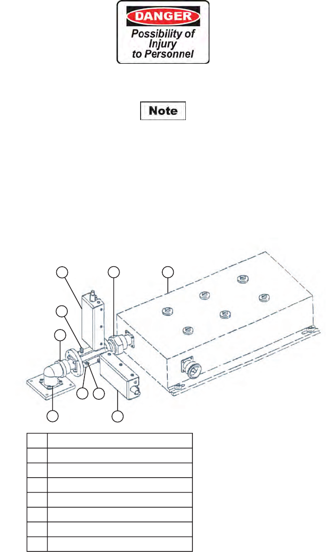
Figure 6 - 5 RF Coupler and Detectors
2
28
4
6
17
5
DTR-1046
07/17/07
3
1 Adapter Plate Securing Hardware
2 RF Coupler Connecting Nuts
3 RF Coupler
4 RF Monitor Cable Connector (FWD)
5 RF Monitor Cable Connector (REF)
6 RF Detector (FWD)
7 RF Detector (REF)
8 Band Pass Filter

Maintenance 3EM21522AAAA
DTR-0200-SA-SIRIUS Issue 1, March 2008
6-18
STEP PROCEDURE
REMOVAL
1Open front and rear doors.
a To Open Front Door
Release two locking screws then release two door latches.
bTo Open Rear Door
Release one locking screw and then release two door latches.
2Coordinate with NMC and switch repeater to Local operating condition.
3Switch OFF all repeater PDU circuit breakers switching repeater main
breaker last.
4Switch OFF commercial power source breaker supplying power to
repeater.
5Hang “DANGER – DO NOT TURN ON – PERSONNEL WORKING” sign at
commercial power source breaker.
Before removing RF detectors, tag each as FWD or REFL. The vertical detec-
tor is the FWD and the horizontal detector is the REFL. Also do the same
with the RF power monitor cables connected to the RF coupler
. If the detec-
tors and the monitor cables are not connected properly during reinstalla-
tion, the RF power feedback signals to the main controller and to the
junction box monitor jacks will be incorrect.
6Loosen SMA connectors on both detectors and remove detectors from
RF coupler.
7Remove monitor cables from RF coupler.
8Loosen RF coupler elbow adapter screws to allow movement of adapter.
9Loosen RF coupler connecting nuts and remove coupler/detector
assembly.

3EM21522AAAA Maintenance
Issue 1, March 2008 DTR-0200-SA-SIRIUS
6-19
STEP PROCEDURE CONT.
REPLACEMENT
10 Install coupler and tighten connecting nuts and elbow adapter screws.
11 Connect RF detectors to new coupler ensuring that proper detector is
connected to the proper connector. Refer to NOTE preceding step 6
above.
12 Connect RF monitor cables to the RF coupler ensuring that proper
cable is connected to proper connector. Refer to NOTE preceding step 6
above.
13 Switch ON commercial power source breaker and remove danger sign.
14 Switch ON repeater main PDU circuit breaker.
15 Switch ON remaining repeater PDU circuit breakers.
16 Access GUI Global Status screen and check RF Power Out values.
17 Set operating mode to Broadcast.
18 Coordinate with NMC and return repeater to Remote operating
condition.
19 Close front and rear doors.
a To Close Front Door
Secure two door latches then tighten two locking screws.
bTo Close Rear Door
Secure two door latches then tighten one locking screw.
6-20 This page intentionally left blank.
3EM21522AAAA Maintenance
Issue 1, March 2008 DTR-0200-SA-SIRIUS
6-21
Chart 5 Remove and Replace Rear Door Intake Fan(s)
Main power to repeater must be off.
Figure 6 - 6 Rear Door Intake Fans
Maintenance 3EM21522AAAA
DTR-0200-SA-SIRIUS Issue 1, March 2008
6-22
STEP PROCEDURE
REMOVAL
1Open front and rear doors
a To Open Front Door
Release two locking screws then release two door latches.
bTo Open Rear Door
Release one locking screw then release two door latches.
2Coordinate with NMC and switch repeater to Local operating condition.
3Switch OFF all repeater PDU circuit breakers switching main breaker
last.
4Switch OFF commercial power source breaker supplying power to
repeater.
5Hang “DANGER – DO NOT TURN ON – PERSONNEL WORKING” sign at
commercial power source breaker.
6Disconnect and remove power wires from fan terminal block (see Figure
6 - 7).
7Remove retaining hardware from fan mounting studs.
8Remove fan from mounting studs.
Figure 6 - 7 Fan Terminal Block

3EM21522AAAA Maintenance
Issue 1, March 2008 DTR-0200-SA-SIRIUS
6-23
STEP PROCEDURE CONT.
REPLACEMENT
9Install new fan on mounting studs.
10 Replace and tighten fan securing hardware.
11 Reconnect power wires to fan terminal block.
12 Switch ON commercial power source breaker and remove danger sign.
13 Switch ON main PDU circuit breaker.
14 Switch ON remaining PDU circuit breakers.
15 Set operating mode to Broadcast.
16 Coordinate with NMC and return repeater to Remote operating
condition.
17 Close front and rear doors.
a To Close Front Door
Secure two door latches then tighten two locking screws.
bTo Close Rear Door
Secure two door latches then tighten one locking screw.
6-24 This page intentionally left blank.
3EM21522AAAA Maintenance
Issue 1, March 2008 DTR-0200-SA-SIRIUS
6-25
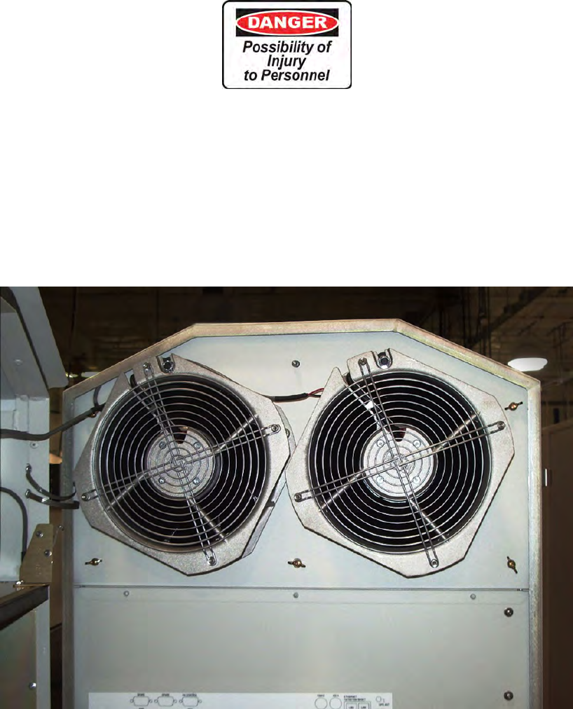
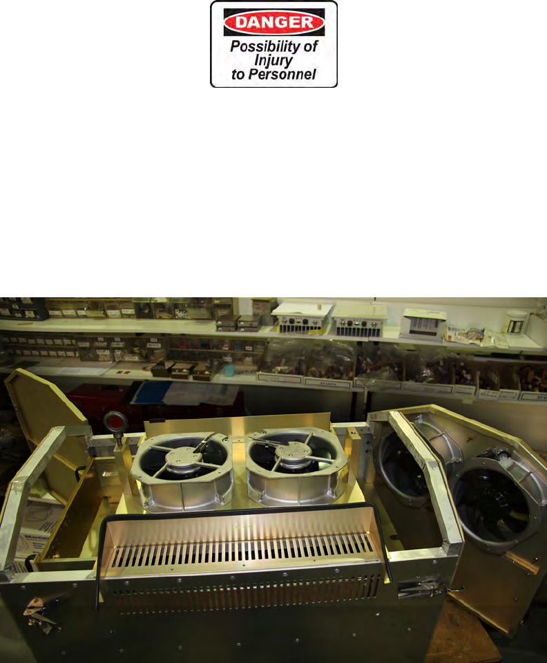
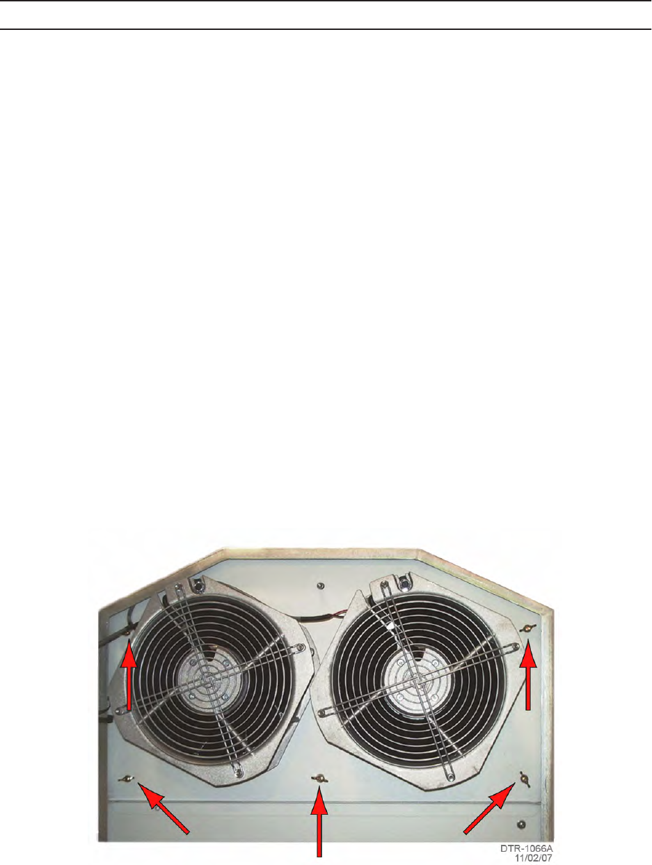
Chart 6 Remove and Replace Under Roof Exhaust Fan(s)
Main power to repeater must be off.
Figure 6 - 8 Under Roof Exhaust Fans

Maintenance 3EM21522AAAA
DTR-0200-SA-SIRIUS Issue 1, March 2008
6-26
STEP PROCEDURE
REMOVAL
1Open front and rear doors.
a To Open Front Door
Release two locking screws then release two door latches.
a To Open Rear Door
Release one locking screw then release two door latches.
2Coordinate with NMC to switch repeater to Local operating condition.
3Switch all repeater PDU circuit breakers to OFF, switching main
breaker last.
4Switch OFF the commercial power source main breaker which supplies
power to repeater.
5Hang “DANGER – DO NOT TURN ON – PERSONNEL WORKING” sign at
commercial power source breaker.
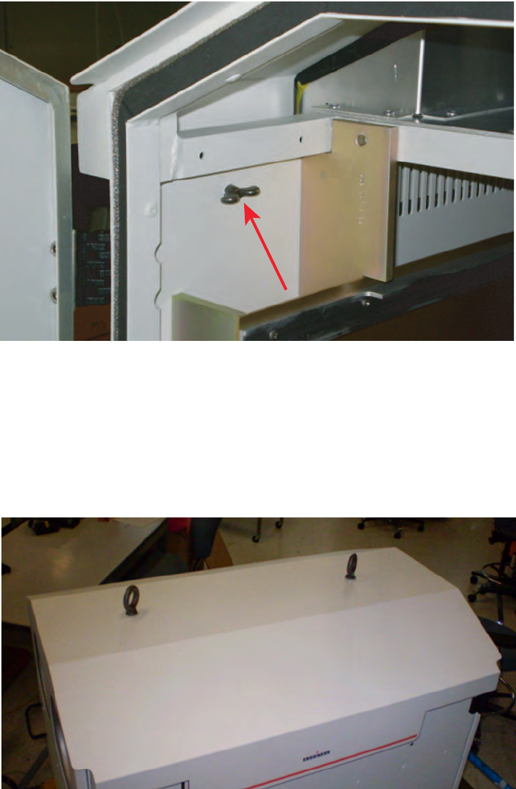
6Remove cabinet roof by removing four wing screws from interior of
cabinet (
Figure 6 - 9
) and two eye bolts and their plastic spacers from
exterior of roof (
Figure 6 - 10
).
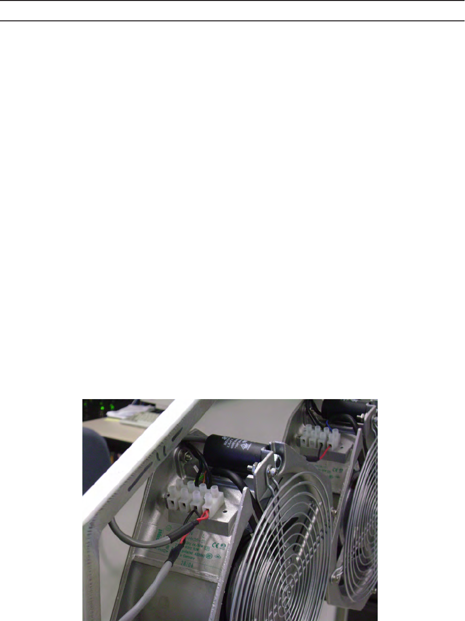
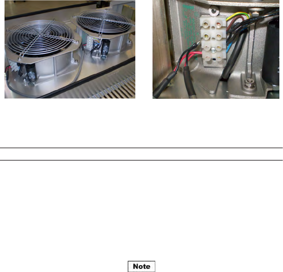
7Disconnect and remove power wires from fan terminal blocks
(
Figure 6 - 11
).
8Remove retaining hardware from fan mounting studs.
9Remove fan(s) from mounting studs.
3EM21522AAAA Maintenance
Issue 1, March 2008 DTR-0200-SA-SIRIUS
6-27
Figure 6 - 9 Internal Wing Screws (4)
Figure 6 - 10 External Eye Bolts and Spacers (2)
DTR-1094
10/31/07
Maintenance 3EM21522AAAA
DTR-0200-SA-SIRIUS Issue 1, March 2008
6-28
.
Figure 6 - 11 Fan Terminal Block
STEP PROCEDURE CONT.
REPLACEMENT
10 Install new fan(s) on mounting studs.
11 Replace and tighten fan securing hardware.
12 Reconnect power wires to fan terminal block.
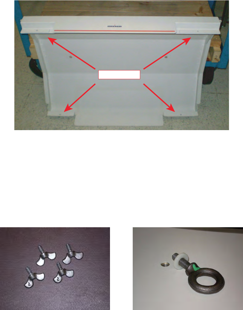
13 Reinstall cabinet roof (
Figure 6 - 12
) and roof securing hardware (
Figure
6 - 13
).
When reinstalling the roof, the side with the larger nut plate goes to the
front of the cabinet.
3EM21522AAAA Maintenance
Issue 1, March 2008 DTR-0200-SA-SIRIUS
6-29
Figure 6 - 12 Roof Showing Nut Plates
Figure 6 - 13 Roof Securing Hardware
Nut Plates
DTR-1095
10/28/07

Maintenance 3EM21522AAAA
DTR-0200-SA-SIRIUS Issue 1, March 2008
6-30
STEP PROCEDURE CONT.
14 Switch on commercial power source main breaker and remove danger
sign.
15 Switch on main PDU circuit breaker.
16 Switch on remaining PDU circuit breakers.
17 Set operating mode to Broadcast.
18 Coordinate with NMC and return repeater to Remote operating
condition.
19 Close front and rear doors.
a To Close Front Door
Secure two door latches then tighten two locking screws.
bTo Close Rear Door
Secure two door latches then tighten one locking screw.
3EM21522AAAA Maintenance
Issue 1, March 2008 DTR-0200-SA-SIRIUS
6-31
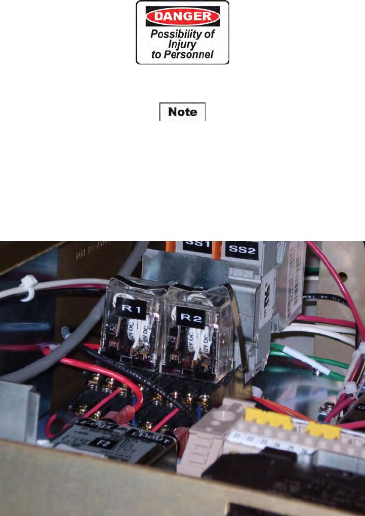
Chart 7 Remove and Replace Fan Relay R1 and/or R2
Main power to repeater must be off.
Relay R1 controls the roof fans; relay R2 controls the rear door fans.
Figure 6 - 14 Fan Relays

Maintenance 3EM21522AAAA
DTR-0200-SA-SIRIUS Issue 1, March 2008
6-32
STEP PROCEDURE
REMOVAL
1Open front and rear doors.
a To Open Front Door
Release two locking screws then release two door latches.
bTo Open Rear Door
Release one locking screw then release two door latches.
2Coordinate with NMC to switch repeater to local operating condition.
3Switch OFF all repeater PDU circuit breakers switching main breaker
last.
4Switch OFF commercial power source breaker supplying power to
repeater.
5Hang “DANGER – DO NOT TURN ON – PERSONNEL WORKING” sign at
commercial power source breaker.
6SPU –
aDisconnect all cables from rear of SPU.
bRemove rack screws from front panel of SPU.
cSlide SPU out of cabinet.
7PDU –
aDisengage the metal strap securing the relay. Use a flat object (e.g.,
screwdriver) along side the relay bottom to pry the band loose.
bUnplug the relay from its socket.

3EM21522AAAA Maintenance
Issue 1, March 2008 DTR-0200-SA-SIRIUS
6-33
STEP PROCEDURE CONT.
REPLACEMENT
8Insert the new relay into its socket.
9Replace metal securing strap on relay.
10 Insert SPU into cabinet.
11 Secure SPU by replacing mounting screws through front panel.
12 Reinstall all connecting cables to rear connectors of SPU.
13 Close rear cabinet door by securing two draw latches and then
tightening door locking screw.
14 Switch ON commercial power source breaker and remove danger sign.
15 Switch ON PDU main circuit breaker.
16 Switch ON PDU remaining circuit breakers.
17 Confirm that all fans are operational.
18 Set operating mode to Broadcast.
19 Coordinate with NMC and return repeater to Remote operating
condition.
20 Close front cabinet door by securing two draw latches and tightening
two door locking screws.
6-34 This page intentionally left blank.
3EM21522AAAA Maintenance
Issue 1, March 2008 DTR-0200-SA-SIRIUS
6-35
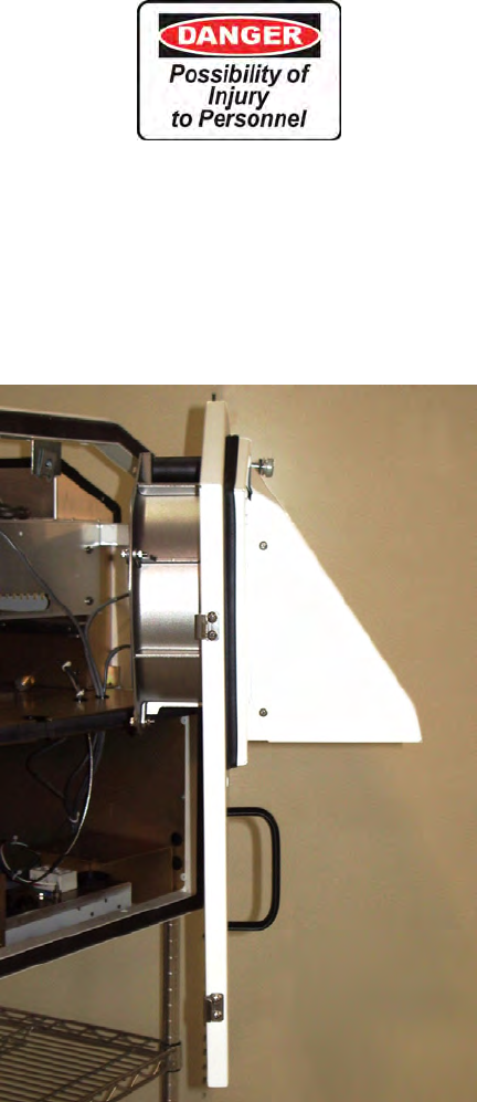
Chart 8 Remove and Replace Rear Door Air Filter
Main power to repeater must be off.
Figure 6 - 15 Rear Door and Filter Assembly
Maintenance 3EM21522AAAA
DTR-0200-SA-SIRIUS Issue 1, March 2008
6-36
STEP PROCEDURE
REMOVAL
1Open front and rear doors.
a To Open Front Door
Release two locking screws then release two door latches.
bTo Open Rear Door
Release one locking screw then release two door latches.
2Coordinate with NMC and switch repeater to Local operating condition.
3Switch OFF all repeater PDU circuit breakers switching main breaker
last.
4Switch OFF commercial power source main breaker supplying power to
repeater.
5Hang “DANGER – DO NOT TURN ON – PERSONNEL WORKING” sign at
commercial power source breaker.
6Remove five filter assembly retaining screws from inside of rear door
(Figure 6 - 16).
7Remove air filter assembly (Filter and Louver Plate/Storm Hood) from
rear door (see
Figure 6 - 17
and
Figure 6 - 18
).
Figure 6 - 16 Filter Assembly Retaining Screws (Inside of Rear Door)
3EM21522AAAA Maintenance
Issue 1, March 2008 DTR-0200-SA-SIRIUS
6-37
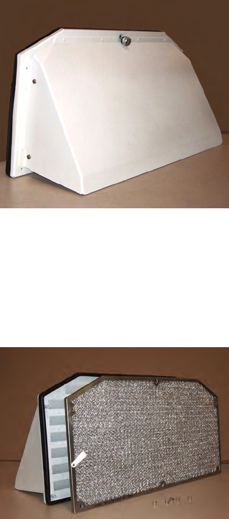
Figure 6 - 17 Air Filter Assembly
Figure 6 - 18 Air Filter Assembly (Filter and Louver Plate)

Maintenance 3EM21522AAAA
DTR-0200-SA-SIRIUS Issue 1, March 2008
6-38
STEP PROCEDURE CONT.
REPLACEMENT
8Install new filter onto louver plate.
9Using five retaining screws, re-attach filter assembly to cabinet rear
door.
10 Switch ON commercial power source main breaker and remove danger
sign.
11 Switch ON main PDU circuit breaker.
12 Switch ON remaining PDU circuit breakers.
13 Set operating mode to Broadcast.
14 Coordinate with NMC and return repeater to Remote operating
condition.
15 Close front and rear doors.
a To Close Front Door
Secure two door latches then tighten two locking screws.
bTo Close Rear Door
Secure two door latches then tighten one locking screw.
3EM21522AAAA Maintenance
Issue 1, March 2008 DTR-0200-SA-SIRIUS
6-39
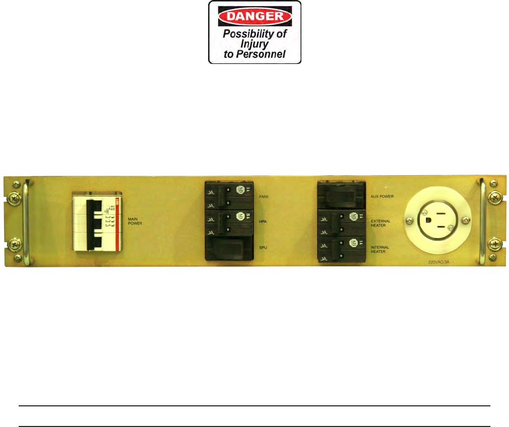
Chart 9 Remove and Replace PDU Front Access Circuit Breakers
Main power to repeater must be off.
Figure 6 - 19 PDU Front Panel
STEP PROCEDURE
REMOVAL
1Open front door.
a To Open Front Door
Release two locking screws then release two door latches.
2Coordinate with NMC and switch repeater to Local operating condition.
3Switch OFF all repeater PDU circuit breakers switching main breaker
last.

Maintenance 3EM21522AAAA
DTR-0200-SA-SIRIUS Issue 1, March 2008
6-40
STEP PROCEDURE CONT.
4Switch OFF commercial power source breaker supplying power to
repeater.
5Hang “DANGER – DO NOT TURN ON – PERSONNEL WORKING” sign at
commercial power source breaker.
6From front of cabinet remove PDU securing screws.
7Carefully pull the PDU away from the rack.
The PDU can only be pulled out approximately six inches.
8Remove the PDU face plate screws.
9For the circuit breaker in question note and label the breaker wiring.
10 Disconnect the wiring for the specific breaker.
11 Remove the breaker securing screws.
12 Remove the breaker.

3EM21522AAAA Maintenance
Issue 1, March 2008 DTR-0200-SA-SIRIUS
6-41
STEP PROCEDURE CONT.
REPLACEMENT
13 Insert new breaker; install and tighten breaker securing screws.
14 Connect and secure breaker wires.
15 Reposition face plate and secure with face plate screws.
16 Set PDU back into the cabinet and secure with mounting screws.
17 Switch ON commercial power source breaker and remove danger sign.
18 Switch ON PDU main circuit breaker.
19 Switch ON PDU remaining circuit breakers.
20 Set operating mode to Broadcast.
21 Coordinate with NMC and return repeater to Remote operating
condition.
22 Close front cabinet door by securing two draw latches and tightening
two door locking screws.
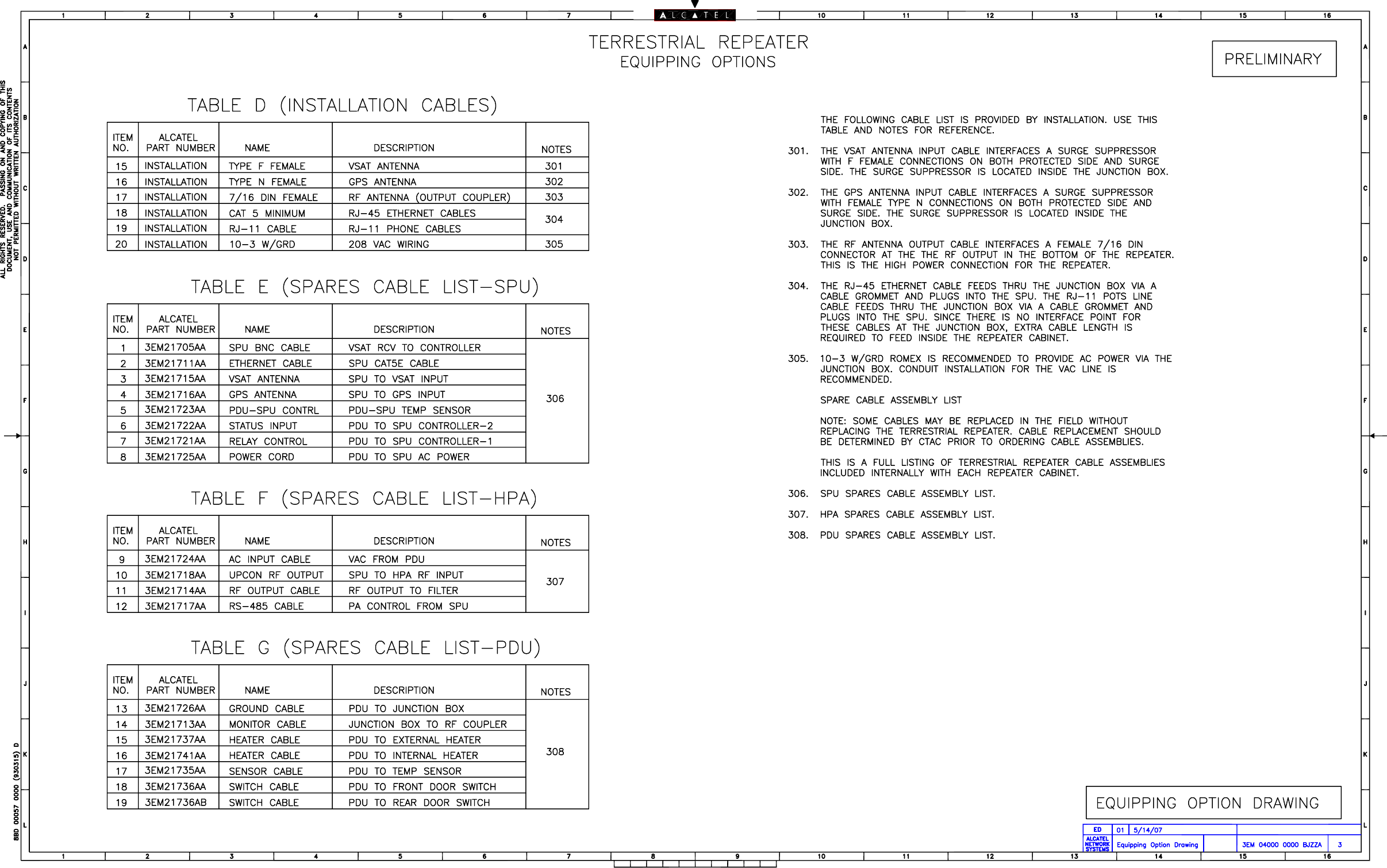
6.10
CABLE REPLACEMENT
For cable replacement refer to Repeater Cable Drawings and part number listing in
Appendix C.
6.11
FINAL SYSTEM TESTING
Refer to Turn-Up and Testing, Section 4, for Repeater System Test procedure.
6-42 This page intentionally left blank.
3EM21522AAAA Appen
d
ix A
Issue 1, March 2008 DTR-0200-SA-SIRIUS
A-1
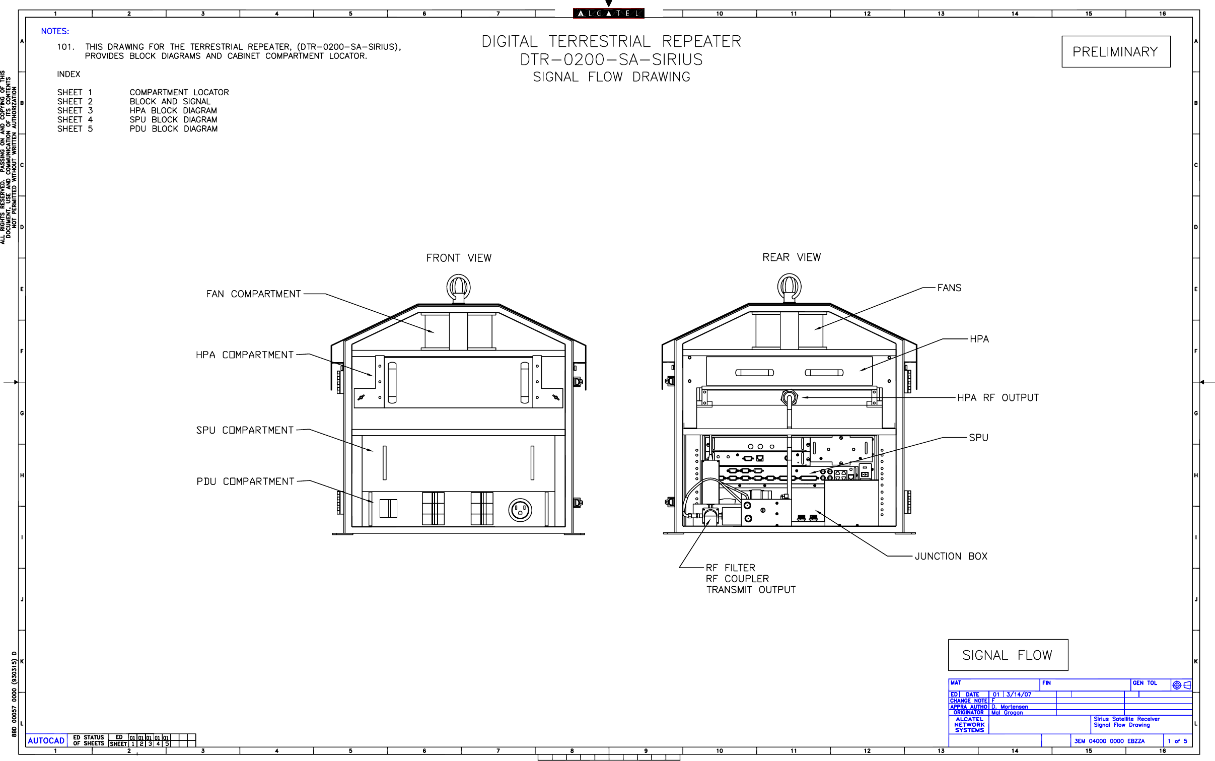
AREPEATER DIAGRAMS
A.1
GENERAL
This section contains repeater support information and drawings.
A.2
LIST OF DRAWINGS
Title Drawing No.
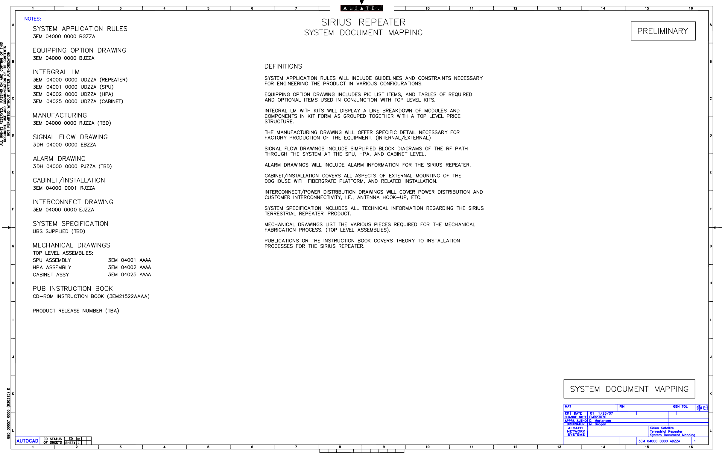
System Document Mapping..................................................................3EM 04000 0000 ADZZA
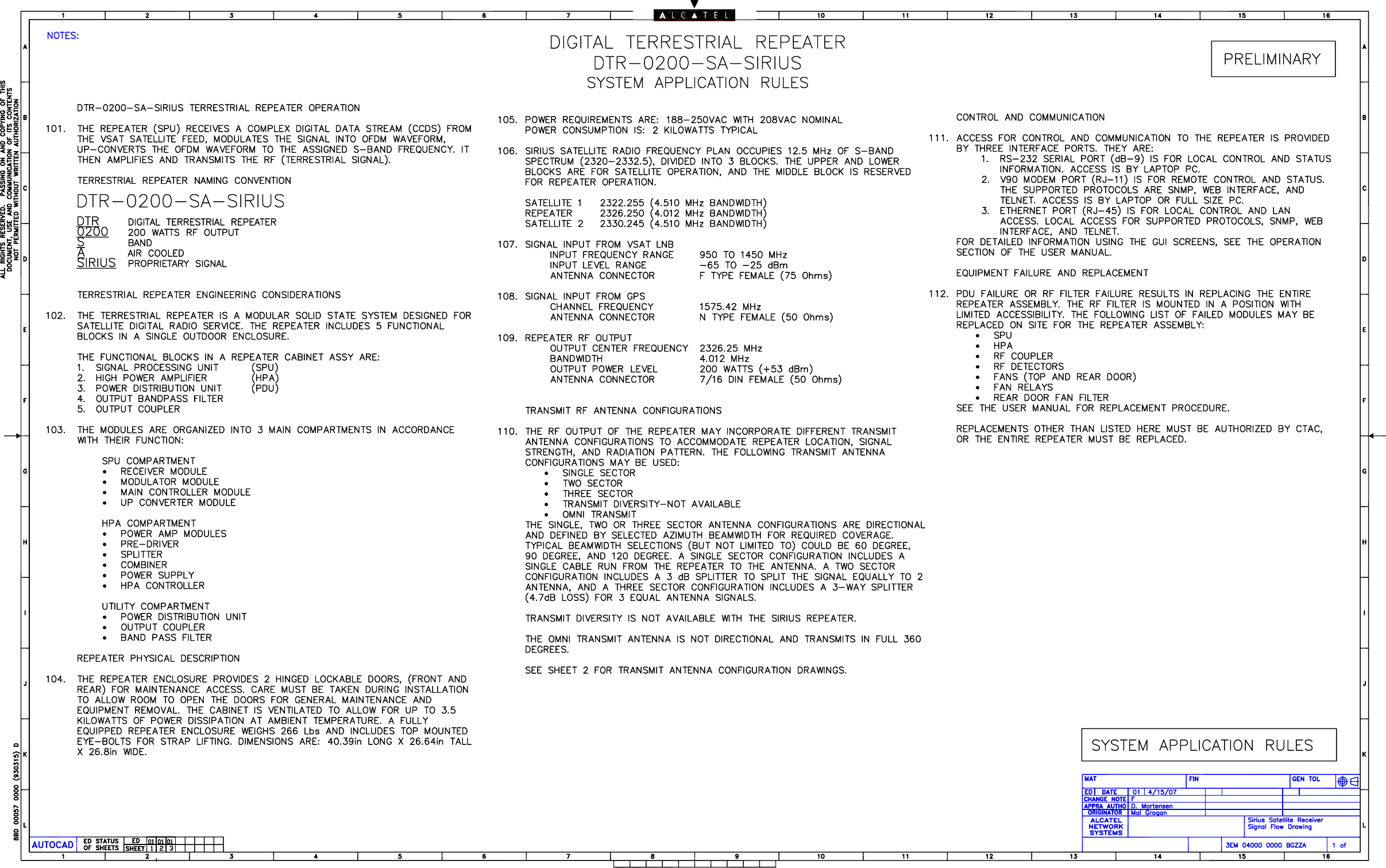
System Application Rules .................................................................... 3EM 04000 0000 BGZZA
(Sheet 1 of 3)
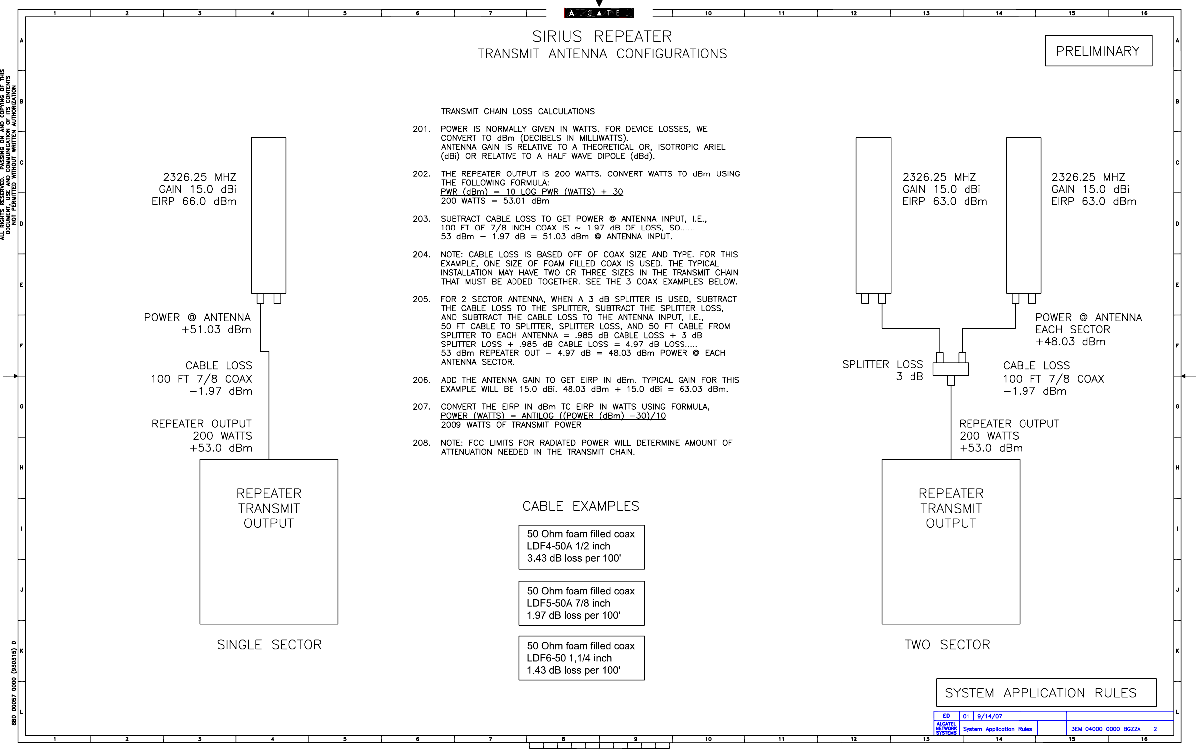
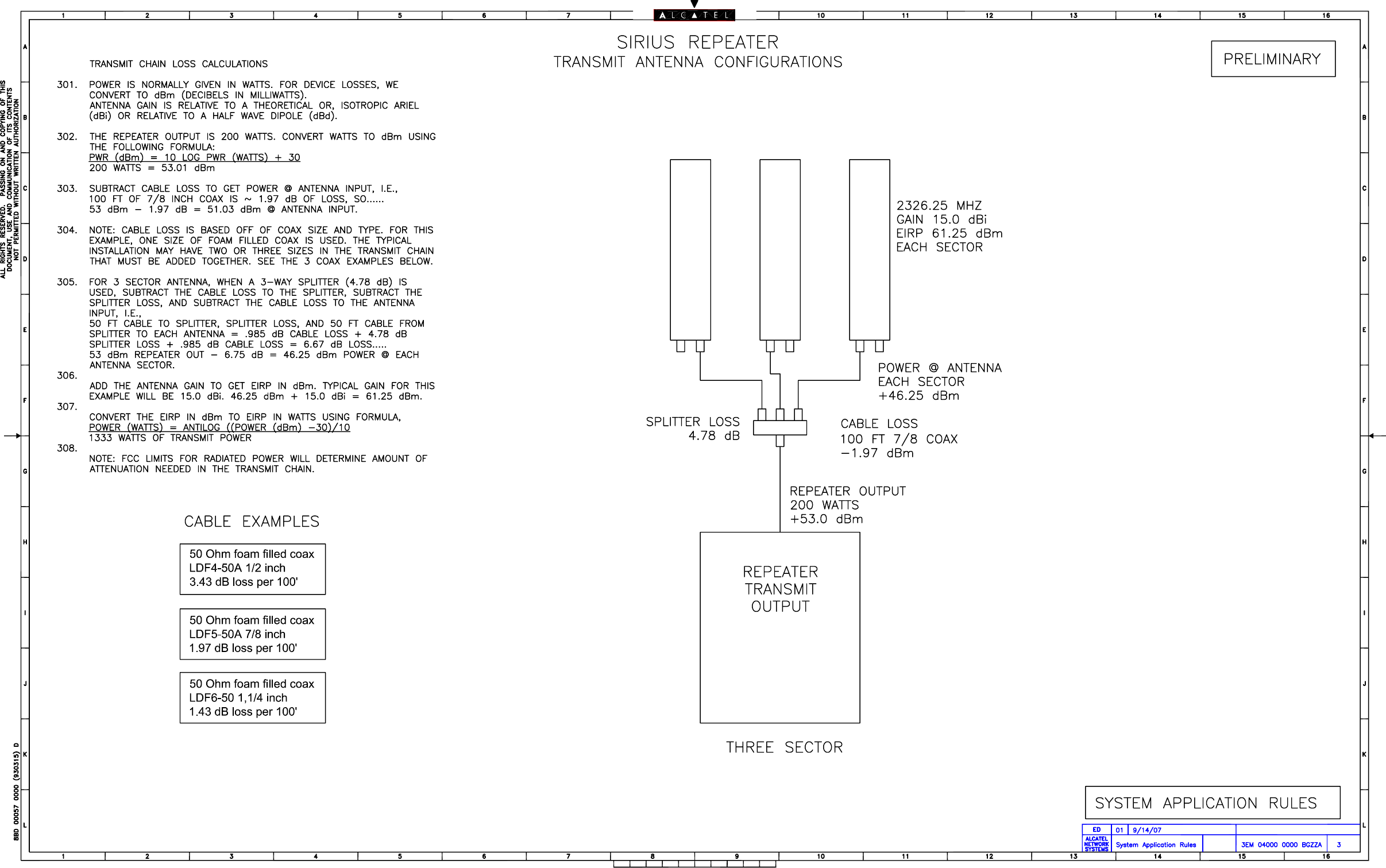
Transmit Antenna Configurations. ..................................................... 3EM 04000 0000 BGZZA
(Sheets 2 and 3 of 3)
Equipping Option Drawing................................................................... 3EM 04000 0000 BJZZA
(3 of 3)
Signal Flow Drawing.............................................................................3EM 04000 0000 EBZZA
(Sheet 1 of 5)
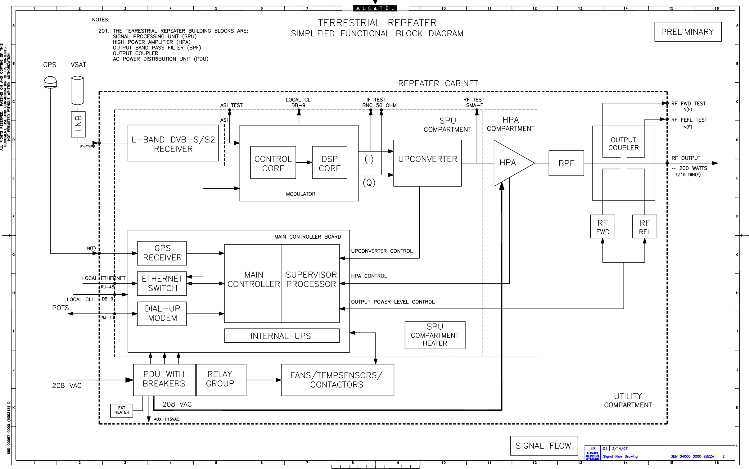
Simplified Functional Block Diagram ..................................................3EM 04000 0000 EBZZA
(Sheet 2 of 5)
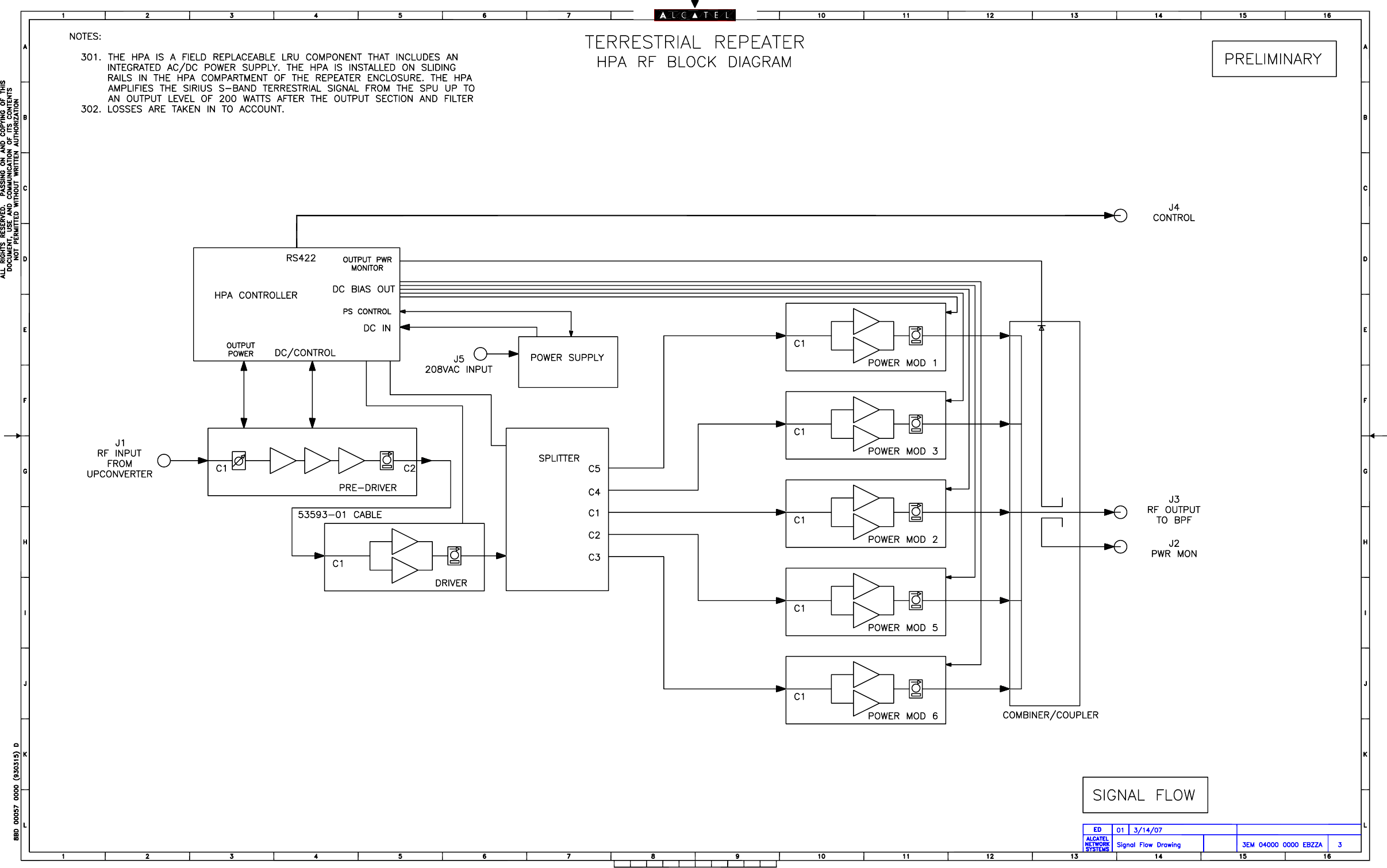
HPA RF Block Diagram ........................................................................3EM 04000 0000 EBZZA
(Sheet 3 of 5)
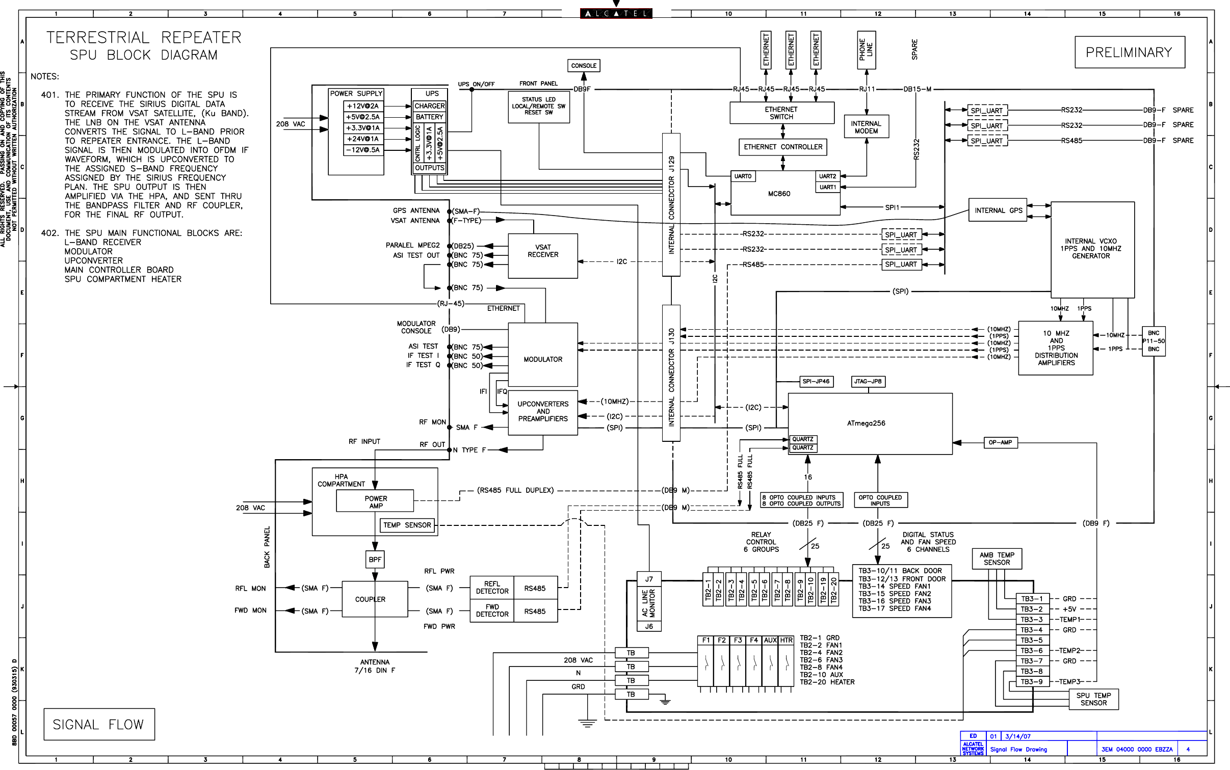
SPU Block Diagram ..............................................................................3EM 04000 0000 EBZZA
(Sheet 4 of 5)
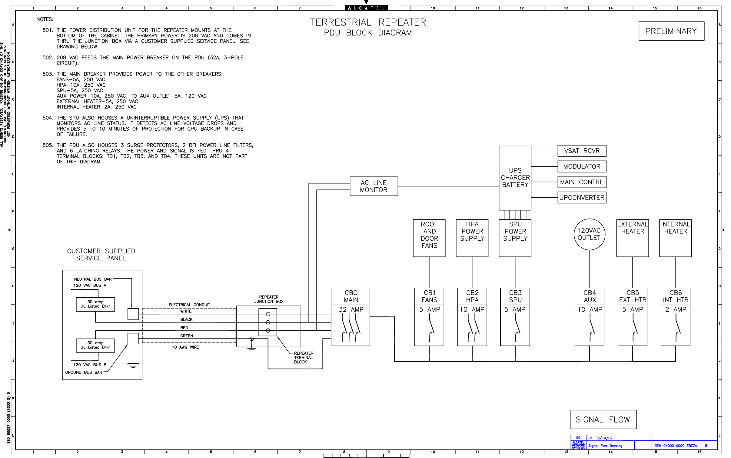
PDU Block Diagram..............................................................................3EM 04000 0000 EBZZA
(Sheet 5 of 5)
A-2 This page intentionally left blank.
3EM21522AAAA Appen
d
ix B
Issue 1, March 2008 DTR-0200-SA-SIRIUS
B-1
BALCATEL-LUCENT PART NUMBERS
B.1
LRU PART NUMBERS
See Table B-1 for Alcatel-Lucent LRU part numbers.
B.2
CABLE PART NUMBERS
See Table B-2 for module connecting cables part numbers and descriptions.
Table B-1 Repeater LRU Part Numbers
Item Alcatel-Lucent Part Number
Repeater Assembly 3EM04000AA
SPU 3EM04001AA
HPA 3EM04002AA
RF Coupler Assembly 3EM21627AA
RF Detector 3EM20401AA
Cabinet Fans 1AB 35914 0001
Fan Relay 1AB 37003 0001
Main Circuit Breaker CB0 1AB 36981 0001
SPU Circuit Breaker CB1 1AB 37239 0002
HPA Circuit Breaker CB2 1AB 37239 0004
Fans Circuit Breaker CB3 1AB 37239 0002
External Heater Circuit Breaker CB4 1AB 37239 0001
Aux Power Circuit Breaker CB5 1AB 37239 0003
Internal Heater Circuit Breaker CB6 1AB 37239 0002
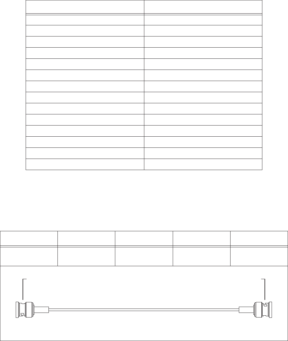
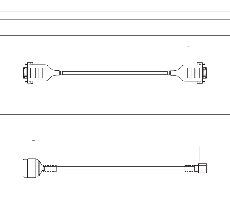
Table B-2 Intermodule Connecting Cables
ALU P/N Connects To Connector Type Connects To Connector Type
3EM21705AA VSAT RCVR
(ASI OUT 2) BNC Straight Plug SPU Controller
(ASI B) BNC Straight Plug
23EM21705AA
BNC Connectors on both ends
ASI OUT 2 on VSAT RX ASI B on Controller
23EM21705AA
06/30/07
Appen
d
ix B 3EM21522AAAA
DTR-0200-SA-SIRIUS Issue 1, March 2008
B-2
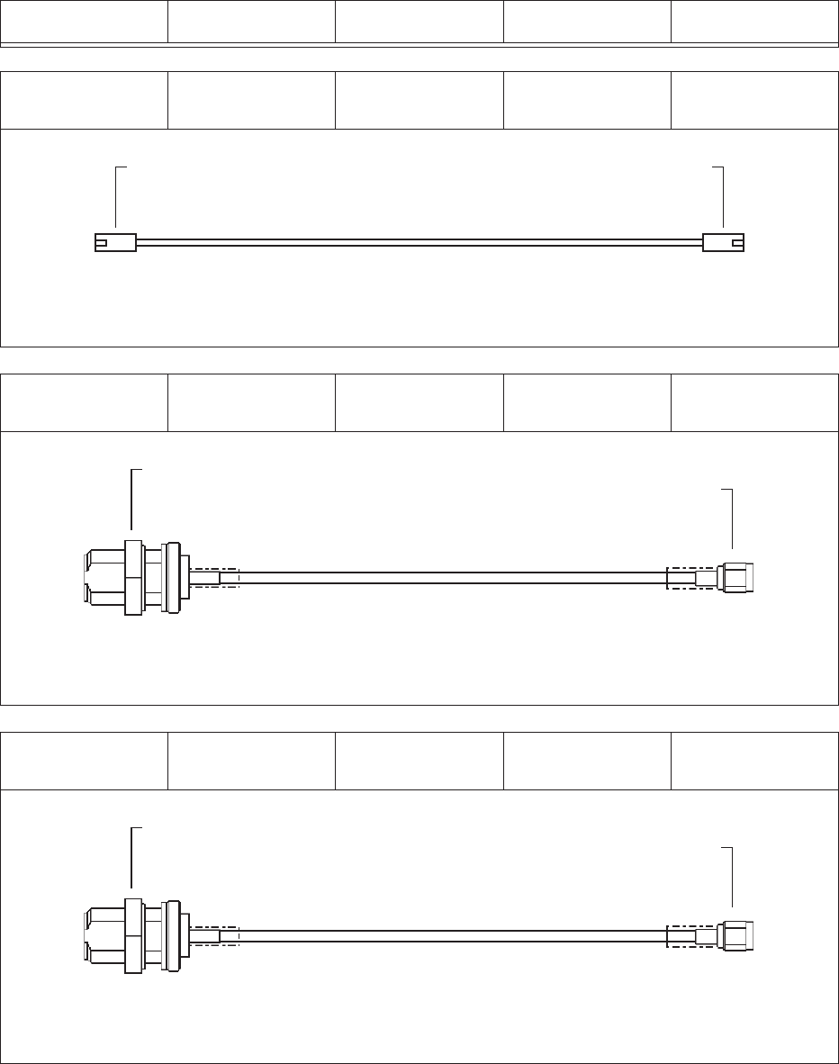
3EM21711AA SPU Modulator
(Ethernet) RJ-45 SPU Controller
(Ethernet) RJ-45
3EM21713AA Junction Box
(CPL FWD) N-Type Connector RF Coupler
(FWD) SMA Straight
Connector
3EM21713AA Junction Box
(CPL REF) N-Type Connector RF Detector
(REF) SMA Straight
Connector
Table B-2 Intermodule Connecting Cables (Continued)
ALU P/N Connects To Connector Type Connects To Connector Type
3EM21711AA
RJ-45 Connectors on both ends
Ethernet Port on Modulator Ethernet Port on Controller
3EM21711AA
06/30/07
3EM21713AA
N-Type Bulkhead Connector SMA Connector On Coupler Side
FWD on Junction Box Panel
FWD RF Coupler
3EM21713AA-FWD
06/30/07
REF on Junction Box Panel
REF RF Coupler
3EM21713AA-REF
06/30/07
3EM21713AA
N-Type Bulkhead Connector SMA Connector On Coupler Side
3EM21522AAAA Appen
d
ix B
Issue 1, March 2008 DTR-0200-SA-SIRIUS
B-3
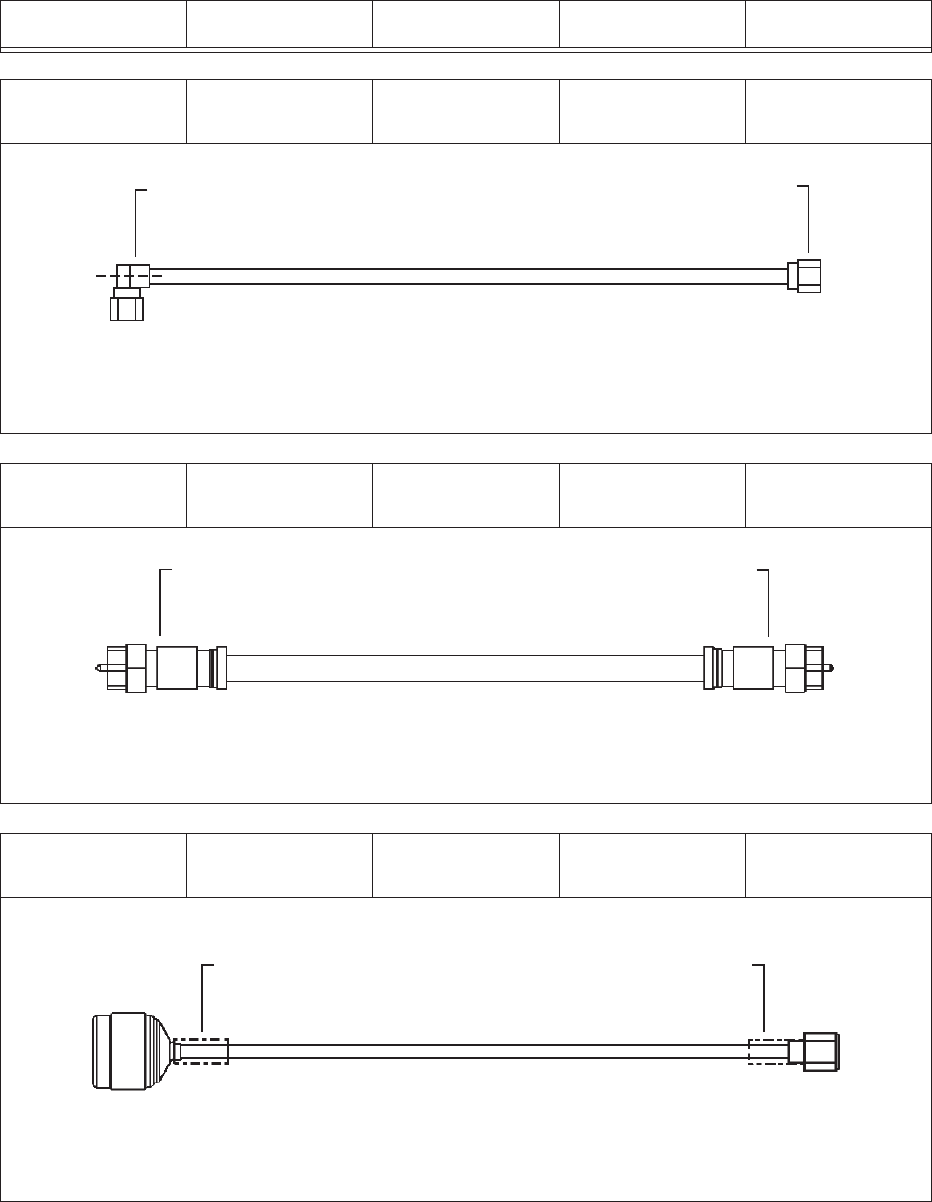
3EM21714AA BP Filter (RF IN) 7/16 DIN Male
Right Angle HPA (RF OUT) 7/16 DIN Male
3EM21715AA Junction Box
(VSAT IN) T&B Snap-N-Seal
Connector VSAT RCVR
(VSAT ANT) T&B Snap-N-Seal
Connector
3EM21716AA Junction Box
(GPS IN) N-Type Straight
Cable Plug SPU Controller
(GPS ANT) SMA Straight
Cable Plug
Table B-2 Intermodule Connecting Cables (Continued)
ALU P/N Connects To Connector Type Connects To Connector Type
3EM21714AA
SMA Connectors on both sides
RF IN on Band Pass Filter RF OUT on HPA
3EM21714A
A
06/30/07
3EM21715AA
T&B Snap-N-Seal Connectors on both sides
VSAT Connector on Junction Box VSAT ANTENNA on VSAT RX
3EM21715AA
06/30/07
3EM21716AA
N-Type Plug at junction box side SMA at Controller side
3EM21716A
A
06/30/07
Heat Shrink Tubing Heat Shrink Tubing
Appen
d
ix B 3EM21522AAAA
DTR-0200-SA-SIRIUS Issue 1, March 2008
B-4
B.3
INTAKE AIR FILTER
PN 3EM22381 AAAA HCZZA
3EM21717AA HPA (IF-RS485) DB-9, Male SPU Controller
(PA CONTROL) DB-9, Female
3EM21718AA HPA (RF IN) N-Type Straight
Cable Plug Up-Converter
(RF OUT) SMA Straight
Cable Plug
Table B-2 Intermodule Connecting Cables (Continued)
ALU P/N Connects To Connector Type Connects To Connector Type
3EM21717AA
DB-9 Connectors on both ends
CONTROL IF on HPA PA CONTROL on Connector
3EM21717AA
06/30/07
3EM21718AA
N-Type Plug at HPA RF OUT on Up-Converter
RF IN on HPA
RF OUT on Up-converter
3EM21718AA
06/30/07

3EM21522AAAA Appen
d
ix C
Issue 1, March 2008 DTR-0200-SA-SIRIUS
C-1
CALARM DESCRIPTION, LIKELY CAUSE, AND SUGGESTED RESPONSE
Alarms are listed alphabetically by alarm names as they appear on the GUI
Alarm screen
Deviating above a positive or below a negative temperature threshold will
cause an alarm as indicated in Table C-1. Following are the temperature
thresholds for the repeater:
C.1
HPA DEFAULT TEMPERATURE THRESHOLD
• HPA Warning Low Temperature . . . . . . . . . . . . . . . . . . . . . -18˚C
• HPA Warning High Temperature . . . . . . . . . . . . . . . . . . . . +78˚C
• HPA Critical Low Temperature. . . . . . . . . . . . . . . . . . . . . . -30˚C
• HPA Critical High Temperature . . . . . . . . . . . . . . . . . . . . . +82˚C
C.2
HPA COLD START OPERATING TEMPERATURE THRESHOLD
This value is in the HPA Controller firmware and cannot be changed by the
operator. When the repeater is cold started below -18˚C in Broadcast or Test
mode, HPA DC power will be on but RF will be off until temperature is
equal to or higher than -18˚C.
• HPA Cold Start Operating Temperature: . . . . . . . . . . . . . . -18˚C
C.3
SPU OPERATING TEMPERATURE THRESHOLD
This value is set on the GUI screen under Config > Temperature
•SPU Operating Temperature Threshold: +75˚C

Appen
d
ix C 3EM21522AAAA
DTR-0200-SA-SIRIUS Issue 1, March 2008
C-2
C.4
ALARM TABLE
See Table C-1 for alarm names, causes, and corrective responses.
Table C-1 Alarms, Possible Causes, and Suggested Response
Alarm Description Possible Cause Operator Response
3.3V Voltage too high SPU 3.3V Voltage is too
high >3.6V SPU Power Supply Fault Replace the SPU
5.0V Voltage too high SPU 5.0V Voltage too
high >5.5V SPU Power Supply Fault Replace the SPU
12.0V Voltage too high SPU 12V Voltage is too
high >13.2V SPU Power Supply Fault Replace the SPU
3.3V Voltage too low SPU 3.3V Voltage is too
low <2.8V SPU Power Supply Fault Replace the SPU
5.0V Voltage too low SPU 5.0V Voltage too
low <4.3V SPU Power Supply Fault Replace the SPU
12.0V Voltage too low SPU 12V Voltage is too
low <10.2V SPU Power Supply Fault Replace the SPU
AC Interruption Occurred 12VDC toggles more
than 10 µs AC power supply voltage
interruption Check AC Power
AC Power Lost UPS 12V, 10V No AC Power Check AC Power
Cabinet Front Door Open Door Open Door Open Close cabinet front door
Cabinet Rear Door Open Door Open Door Open Close cabinet rear door
DSP Error DSP is not responding Possibly there is a hard-
ware problem or software
issue.
If reset doesn’t clear the
problem – Replace SPU
(fault in Modulator).
Ethernet Connection
Failure No communication via
Main Controller Ethernet
switch port
Communication Error Check Ethernet cable
Forward Power Detector
Comm Error Communication timeout Error communicating to
the Forward power
detector on the output
coupler
Replace Detector and/or
SPU (Main Controller
and/or Detector fault).
GPS Comm Error Problem communicating
with GPS receiver Problem communicating
with GPS receiver Replace SPU (Main Con-
troller fault)
GPS Holdover Duration
Exceeded Holdover process is too
long Check “Max GPS Hold-
over Time” parameter
and make sure it is set
properly.
Refer to Section 5, Fig-
ure 5-17. Adjust “Max
GPS Holdover Time”
parameter.
GPS Quality Low GPS Signal Quality is low Antenna disconnected Check Antenna connec-
tion to the GPS

3EM21522AAAA Appen
d
ix C
Issue 1, March 2008 DTR-0200-SA-SIRIUS
C-3
GPS Surveillance Error Problem detected on
GPS receiver Problem detected on
GPS receiver Replace SPU (Main Con-
troller fault)
Heartbeat Alarm notifies NMS that
repeater is alive Transmission interval
defined by “Heartbeat
Pace”
No action required
HPA Comm Error No communication
between HPA and Main
Controller
No communication
between HPA and Main
Controller
Check Comm cable
between HPA and Main
Controller
HPA Driver/Pre-driver/
Module Faults Possibly over-current sit-
uation due to signal con-
ditions
Possibly over-current sit-
uation due to signal con-
ditions
If HPA is in Broadcast
mode and reset doesn’t
resolve the problem –
replace the HPA.
HPA Forward Power
Fault Forward power exceeded
hard limit
Warning ≥ 56 dBm
Critical ≥ 56.5 dBm
At critical condition, HPA
turns off
Problem with HPA out-
put circuit, Output Filter,
Detector, output connec-
tor, or antenna cable.
Investigate Output Filter,
Detector, output connec-
tor, or antenna cable. If
no fault found, replace
HPA
HPA Hardware Fault Fault with RF modules,
PS, or Controllers Fault with RF modules,
PS, or Controllers Replace the HPA
HPA Input Power Fault Input power exceeded
hard limit
Warning ≥3 dBm
Critical ≥5 dBm
At critical condition, HPA
turns off
Input power from SPU
too high Replace SPU
HPA Operation Alarm
HPA Output power is close to operating
thresholds.
HPA Output power is
close to operating
thresholds.
Check the output power
of the HPA with a power
meter. If the power is too
close to the threshold
check the loss on cables
between the HPA and
output filter.
HPA PS Alarms Power supply failure Power supply failure Replace the HPA
HPA Reflected Power
Fault Reflected power
exceeded hard limit
Warning ≥ 45 dBm
Critical ≥ 47 dBm
At critical condition, HPA
turns off
Problem with HPA out-
put circuit, Output Filter,
Detector, output connec-
tor, or antenna cable.
Investigate Output Filter,
Detector, output connec-
tor, or antenna cable.
If no fault found, replace
HPA.
HPA Shutdown HPA inoperative Shutdown caused by any
critical condition Replace HPA
Table C-1 Alarms, Possible Causes, and Suggested Response (Continued)
Alarm Description Possible Cause Operator Response

Appen
d
ix C 3EM21522AAAA
DTR-0200-SA-SIRIUS Issue 1, March 2008
C-4
HPA Temperature Fault HPA turns off HPA Temperature is
above the Critical High
Temperature level,
+82°C.
Check input, output ven-
tilation vents. Verify fans
are operational. If no fault
found, replace HPA.
HPA Temperature Fault
Low HPA turns off HPA Temperature is
below the Critical Low
Temperature level, -30°C
Replace HPA
HPA Temperature Warn-
ing HPA Temperature is
above the Warning High
Temperature level, +78˚C
HPA Temperature is
above the Warning High
Temperature level, +78˚C
Check input, output ven-
tilation vents. Verify fans
are operational. If no fault
found, replace HPA.
HPA Temperature Warn-
ing Low HPA Temperature is
below the Warning Low
Temperature level, -18°C
HPA Temperature is
below the Warning Low
Temperature level, -18°C
Replace HPA
Local Control Engaged Triggered when repeater
is switched to Local or
Remote condition
Condition changes when
Local/Remote switch is
pressed
No action required
Module 0 HPA PS Volt-
age Fault AC voltage on PS mod-
ule 0 is off AC voltage on PS mod-
ule 0 is off Replace HPA
Module 1 HPA PS Volt-
age Fault DC voltage on PS Mod-
ule 0 >32 V or <10 V DC voltage on PS Mod-
ule 0 >32 V or <10 V Replace HPA
Module 2 HPA PS Volt-
age Fault AC voltage on PS mod-
ule 1 is off AC voltage on PS mod-
ule 1 is off Replace HPA
Module 3 HPA PS Volt-
age Fault DC voltage on PS Mod-
ule 1 >32 V or <10 V DC voltage on PS Mod-
ule 1 >32 V or <10 V Replace HPA
Module 4 HPA PS Volt-
age Fault AC voltage on PS mod-
ule 2 is off AC voltage on PS mod-
ule 2 is off Replace HPA
Module 5 HPA PS Volt-
age Fault DC voltage on PS Mod-
ule 2 >32 V or <10 V DC voltage on PS Mod-
ule 2 >32 V or <10 V Replace HPA
Module 6 HPA PS Volt-
age Fault AC voltage on PS mod-
ule 3 is off AC voltage on PS mod-
ule 3 is off Replace HPA
Module 7 HPA PS Volt-
age Fault DC voltage on PS Mod-
ule 3 >32 V or <10 V DC voltage on PS Mod-
ule 3 >32 V or <10 V Replace HPA
PA Module 0, 1, 2, 4, 5 or
Driver Module TR1 Volt-
age Fault
This alarm is triggered
when the voltage on tran-
sistor 1 exceeds 32 volts
or goes below 26 volts
Wrong voltage on tran-
sistor 1 Replace HPA
Table C-1 Alarms, Possible Causes, and Suggested Response (Continued)
Alarm Description Possible Cause Operator Response

3EM21522AAAA Appen
d
ix C
Issue 1, March 2008 DTR-0200-SA-SIRIUS
C-5
PA Module 0, 1, 2, 4, 5 or
Driver Module TR2 Volt-
age Fault
This alarm is triggered
when the voltage on tran-
sistor 2 exceeds 32 volts
or goes below 26 volts
Wrong voltage on tran-
sistor 2 Replace HPA
PA Module 0, 1, 2, 4, 5,
or Driver Module TRI
Current Fault
This alarm is triggered
when the current on tran-
sistor 1 exceeds 7
ampere or goes below
0.7 ampere
Wrong current on transis-
tor 1 Replace HPA
PA Module 0, 1, 2, 4, 5 or
Driver Module TR2 Cur-
rent Fault
This alarm is triggered
when the current on tran-
sistor 2 exceeds 7
ampere or goes below
0.7 ampere
Wrong current on transis-
tor 2 Replace HPA
PA Module 0, 1, 2, 4, 5 or
Driver Module Bias Volt-
age Fault
This alarm is triggered
when the BIAS voltage
exceeds 12 volts or goes
below 7 volts
Wrong BIAS voltage on
module Replace HPA
Modulator Comm Error Communication error
with the modulator IP Address of the modu-
lator is not set on the
Main Controller
Check the IP address of
the modulator on the
main controller – it
should correspond to the
IP address of the modu-
lator verified through the
CLI. Also check if the
MAC address of the
modulator is correct. If
everything is correct –
replace the SPU (modu-
lator fault)
Modulator Restarted Modulator fault Modulator internal fault Replace the SPU
No Lock to Input Stream Either bad connection
between the VSAT and
Modulator or VSAT is
unlocked
Check Satellite signal –
in this case this alarm will
come together with VSAT
alarm.
If there is no VSAT alarm
– check the cable con-
nection between the
modulator and the VSAT.
In case the VSAT alarm
is there – check the
VSAT cable. If it fails,
replace SPU (fault in
modulator and/or VSAT).
No Lock to OIM Block Normal if input stream is
of Legacy type. Error
decoding the incoming
stream of Overlay type.
Hardware problem with
the modulator or the
modulator is in the syn-
chronization stage
If this alarm appears
without VSAT/SFN
alarms – Replace SPU
(fault in Modulator).
Table C-1 Alarms, Possible Causes, and Suggested Response (Continued)
Alarm Description Possible Cause Operator Response

Appen
d
ix C 3EM21522AAAA
DTR-0200-SA-SIRIUS Issue 1, March 2008
C-6
Over Temperature Fault Ambient temperature is
above the user defined
threshold
Roof exhaust fan(s) or
rear door intake fan(s)
inoperative.
Check fans operation.
Replace fan(s) where
necessary.
Pre-Driver LDMOS Volt-
age Fault This alarm is triggered
when the voltage on
LDMOS transistor
exceeds 32 volts or goes
below 26 volts
Wrong voltage on Pre-
Driver LDMOS device Replace HPA
Pre-Driver LDMOS Cur-
rent Fault This alarm is triggered
when the current on
LDMOS transistor
exceeds 2 ampere or
goes below 0.4 ampere
Wrong current on Pre-
Driver LDMOS device Replace HPA
Pre-Driver Bias Voltage
Fault This alarm is triggered
when the BIAS voltage
exceeds 12 volts or goes
below 7 volts
Wrong BIAS voltage on
Pre-Driver Replace HPA
Pre-Driver GaAs Current
Fault This alarm is triggered
when the current on
GASFET transistor
exceeds 0.6 ampere or
goes below 0.1 ampere
Wrong current on Pre-
Driver GASFET device Replace HPA
Pre-Driver GaAs Voltage
Fault This alarm is triggered
when the voltage on
GASFET exceeds 13
volts or goes below 9
volts
Wrong voltage on Pre-
Driver GASFET device Replace HPA
Reflected Power Alarm
Difference between
HPA Forward power and
HPA Reflected power
exceeds the Return Loss
Threshold
Return Loss Threshold is
not set up right, the
reflected power on the
coupler is too high, or the
actual return loss is bad.
Check the Return Loss
Threshold as well as the
reflected power reported
by the detector. If the
power is reported incor-
rectly – replace the
detector.
Reflected Power Detec-
tor Comm Error Communication timeout Error communicating to
the reflected power
detector on the output
coupler
Replace Detector and/or
SPU (Main Controller
and/or Detector fault).
Satellite Receiver
Unlocked VSAT Receiver problem No VSAT input signal Check VSAT input signal
level. If good VSAT sig-
nal is present, replace
SPU
Table C-1 Alarms, Possible Causes, and Suggested Response (Continued)
Alarm Description Possible Cause Operator Response

3EM21522AAAA Appen
d
ix C
Issue 1, March 2008 DTR-0200-SA-SIRIUS
C-7
Satellite Receiver Comm
Error VSAT Receiver problem No VSAT input signal Check VSAT input signal
level. If good VSAT sig-
nal is present, replace
SPU
SFN Timing Error Synchronization problem This alarm is typically
raised in the beginning of
the synchronization
stage and shall disap-
pear within 16 sec.
Refer to Section 5, Fig-
ure 5-12. If the alarm is
raised persistently and
accompanied with re
synchronization – check
the delays preset in the
system. The target delay
should be more than 1
second, but less than 6
seconds.
SPU Over Temperature
Fault SPU temperature above
the threshold SPU temperature is too
high, or Operating Tem-
perature Threshold is not
set
Refer to Section 5, Fig-
ure 5-18. Check for valid
Operating Temperature
Threshold.
Supervisor Controller
Comm Error I2C communication error No communication with
Supervisor Processor in
Main Controller
Replace SPU
Sync 1PPS Fault 1PPS signal is not
detected by the modula-
tor
Intermittent connection
on the backplane, Main
Controller, Modulator
Replace the SPU
Sync 10MHz Fault 10MHz signal is not
detected by the modula-
tor
Intermittent connection
on the backplane, Main
Controller, Modulator
Replace the SPU
Sync Lost GPS signal lost, or prob-
lem with Modulator or
Main Controller modules
GPS signal lost, or prob-
lem with Modulator or
Main Controller modules
Check GPS input. If GPS
is present, replace SPU.
Up-converter Fault Up-converter PLL
unlocked Up-converter PLL
unlocked
Up-converter Comm
Error Communication error
with up-converter in SPU Communication error
with up-converter in SPU Replace SPU
VCXO Unlocked 10 MHz not locked to
1PPS 10 MHz not locked to
1PPS Replace SPU
VSAT Comm Error Error communicating with
VSAT Receiver located in
the SPU
Possible SPU backplane
or VSAT Receiver fault Replace SPU
VSAT LNB Power Fault LNB Power block hard-
ware failure Power block hardware
failure Check voltage to LNB. If
good, replace LNB.
Table C-1 Alarms, Possible Causes, and Suggested Response (Continued)
Alarm Description Possible Cause Operator Response

Appen
d
ix C 3EM21522AAAA
DTR-0200-SA-SIRIUS Issue 1, March 2008
C-8
VSAT LNB Over Current Antenna shorted Antenna shorted Investigate antenna &
antenna cable.
VSAT Receiver Internal
Fault Typically comes along
with Satellite Receiver
Unlocked
Any alarm on the satellite
receiver If the receiver is locked
but there is an internal
fault, replace the SPU
VSAT Unlocked VSAT signal lost VSAT unlocked to input
signal Check VSAT input signal
Wrong Input Stream
Type The incoming stream
doesn’t match the set
parameters in “Input
Stream Type”
“Input Stream Type” is
set to Legacy while the
incoming stream is Over-
lay
Refer to Section 5, Fig-
ure 5-10. Switch the
“Input Stream Type” to
Overlay or Legacy to
match the incoming
stream. Set this parame-
ter to Auto to avoid fur-
ther problems.
If no alarms are received from the modulator during the power-up – check the “Main Controller Address”
parameter on the modulator.
Table C-1 Alarms, Possible Causes, and Suggested Response (Continued)
Alarm Description Possible Cause Operator Response