Sirius XM Radio DTR0200 ALU Repeater User Manual 00 DTR Iss 1
Sirius XM Radio Inc. ALU Repeater 00 DTR Iss 1
Contents
- 1. Users Manual Part 1
- 2. Users Manual Part 2
Users Manual Part 1
3EM21522AAAA
Front Matter
Issue 1, March 2008
DTR-0200-SA-SIRIUS
FM-
1
FRONT MA
TTER:
Inc
ludes the general manual la
yout by section,
customer service cen
-
ter information,
telephone tec
hnical support information,
safety precautions
,
and
w
arranty/repair information.
GENERAL
– SECTION 1:
Provides a general description of the system to inc
lude its pur
-
pose and a high level breakdown of components
.
T
ables list physical,
environmental,
and electrical c
haracteristics;
equipment supplied;
optional equipment;
and equip
-
ment required but not supplied.
FUNCTIONAL DESCRIPTION
– SECTION 2:
Describes operation of the overall equipment,
any subsystems/sub functions
,
and the purpose/function of eac
h module/unit.
INSTALLATION
– SECTION 3:
Contains instructions for the installation of the SIRIUS
repeater;
also references supporting engineering dra
wings
.
TURNUP AND TEST – SECTION 4:
Procedures to turn-up the DTR-0200-SA-SIRIUS
repeater after installation.
Also provides post-installation and post-maintenance sys
-
tem test procedures
.
OPERA
TION
– SECTION 5:
Provides procedures/information for normal operation,
use
of graphical user interface
,
and all controls
,
indicators
,
test points
,
and connectors
used for installation,
operation,
and maintenance
.
MAINTENANCE – SECTION 6:
Describes the maintenance philosophy and method
applicable to the equipment,
lists recommended test equipment,
identifi
es and
inc
ludes recommended periodic c
hec
ks
,
inc
ludes troubleshooting/analysis informa
-
tion,
identifi
es actions required after module replacement,
and inc
ludes post-
repair/replacement c
hec
k and adjustment procedures
.
APPENDIX A:
Contains repeater dra
wings to support information presented in this
Operation and Maintenance (O & M) manual.
APPENDIX B:
Contains
Alcatel-Lucent part numbers
.
APPENDIX C:
Lists locally correctable alarms
,
their probable causes
,
and suggested
responses
.

NORTH AMERICA CUSTOMER SERVICE CENTER
24 HOURS PER DAY, 7 DAYS PER WEEK
PHONE the Call Center at
888-252-2832 (US and Canada)
or
613-784-6100 (International)
ALCATEL-LUCENT’S PRIMARY MISSION IS
SATISFYING OUR CUSTOMERS' QUALITY EXPECTATIONS.
The Call Center Agent (CSA)
Will help connect you with Technical Assistance (TAC)
Or assist you with a Repair and Return
• Phone-based technical support
• After-hour emergencies
• On-site technical support
• E-mail support ml-tac.support@alcatel-lucent.com
• Software and hardware upgrades
TAC
• Module repair
Repair and Return
• Training http://www.alcatel-lucent.com>support
– Technical Training
Other Services Offered
• Field Services
– Installation and test
• Customized and Comprehensive Service Agreements
• Registration http://www.alcatel-lucent.com>MyAccess
– Once registered
– From “MyAlcatel” go to “Alcatel Support Documentation”
–
Register for access to Documentation and e-mail Update notifications
For Product Change Notices (PCN), Product Documentations, etc.
– Software and Hardware upgrade documentation

Telephone Assistance, Normal Working Hours (CST 8am 5pm M-F)
TAC supports all Alcatel North America Microwave products. This includes routine questions and
emergency service.
Telephone Assistance, Emergency After-Hours
• Defined as loss of traffic, standby equipment, or network visibility on traffic-bearing systems.
• Available through our Customer Service Agents (CSA).
Contact Information Ask the Customer Service Agent (CSA) for a Microwave (MW) or a Network
Management Service engineer (NMS).
Please provide the following information to the Customer Service Agent (CSA):
• Last and First name
• Company name
• Telephone number
• City and state (Street address if applicable) or Site Name and Location
• Equipment type
• A brief description of the problem affecting their equipment
• Customer Priority: High, Medium, or Low.
• TL-9000 Severity as described below.
Creating a TAC Action Request (AR)
Critical
TL-9000 Severities Defined
Major
Minor Problems not classified as critical or major.
Problems severely affecting service, traffic, capacity, or network
management. They require immediate corrective action. (Ex.
Loss of network management capability, loss of traffic imminent
or existing).
Conditions seriously affecting system operation. They require
immediate attention. (Ex. processor outage, loss of standby
equipment, loss of remote access, or network managers).
TAC
Technical Assistance Center

Front Matter
3EM21522AAAA
DTR-0200-SA-SIRIUS
Issue 1, March 2008
FM-
4
SAFETY PRECAUTIONS
P
ersonnel should use caution when installing, testing, operating, and servicing this
equipment.
As with all electronic equipment, care should be taken t avoid electrical shock where
substantial currents or voltages may be present.
Definitions of Danger, Warnings, Cautions, and Notes used throughout this manual
are described below.
An operating pr
ocedure, practice, etc., which, if not correctly
followed could result in personal injury or loss of life.
An operating pr
ocedure, practice, etc., which, if not strictly
observed, could result in damage to equipment.
An operating procedure, practice, etc., which, if not strictly
observed, could result in an interruption of service.
An operating procedure
, condition, etc., which is essential to highlight.

3EM21522AAAA
Front Matter
Issue 1, March 2008
DTR-0200-SA-SIRIUS
FM-
5
ELECTRICAL SAFETY
: GENERAL RULES
Carefully observe the specifi
c procedures for installation, turnup, and mainte-
nance where AC or DC power is present and observe the following general infor-
mation/rules.
• Remove rings, watches, and other metal jewelry. Short circuits in low-voltage, low-
impedance DC circuits can cause severe arcing that my result in burns or eye
injury. Exercise caution to avoid shorting power input terminals.
•
This equipment is intended for installation in a RESTRICTED ACCESS
LOCATION ONLY.
•
Installation and maintenance are to be performed only by technically qualified
professional personnel.
ST
ATIC ELECTRICITY
When the above symbol or letters are displayed, observe special precautions.
An electrostatic-sensitive device can be weakened, damaged or destroyed even by a
minute discharge that would even go unnoticed by a technician.
Common plastics, clothing, and paper or cardboard are the most common sources of
static charges.
Common plastic, white foam, cellophane and masking adhesive tapes must not come
in contact with ESS devices or their packaging.
Front Matter 3EM21522AAAA
DTR-0200-SA-SIRIUS Issue 1, March 2008
FM-6
MODULE HANDLING
To minimize risk of damage to an ESS device:
• All modules should be handled as static sensitive devices
• Heel straps are only effective while standing on conductive or static dissipative
surfaces
• Ground straps, either wrist (PN 055-9357-010) or heel (PN 055-9357-020), should
be worn prior to and while touching or handling modules containing ESS devices.
• Surfaces (with resistance to ground in excess of 100 Meg-ohms), such as ordinary
tile, should be covered with properly grounded static dissipative runners or waxed
with a static dissipative wax (PN 057-4000-006)
• Modules (even temporarily) should be stored, packed, or shipped in antistatic bags
or containers
• Do not handle modules by touching the electrical components and circuit board.
Use the plastic handle or other outside casing
• Use only ESS rated cleaning devices to clean modules
• Be sure to handle failed modules with the same precautions as good modules
WARRANTY/REPAIR INFORMATION
GENERAL WARRANTY PROVISIONS
Alcatel-Lucent guarantees to repair or replace, or refund the complete purchase
price of any equipment, accessories or parts manufactured by Alcatel-Lucent, which
are defective as to workmanship, or material, provided that:
• Notice of the claimed defect or unsuitability is given in writing to Alcatel-Lucent
within the warranty period after delivery, acceptance, or use, whichever is earlier.
• The defective or unsuitable equipment, accessory, or part is returned to Alcatel-
Lucent at its factory (transportation prepaid), in accordance with the instructions
given in the Module Return section below.
• An inspection of the returned goods by Alcatel-Lucent at its factory indicates that
the defect was not caused by abuse or improper use, maintenance, repair, or alter-
ation by other than Alcatel-Lucent or its authorized service center.
3EM21522AAAA Front Matter
Issue 1, March 2008 DTR-0200-SA-SIRIUS
FM-7
MODULE RETURN
Call Repair and Return Customer Service Agent (CSA) at 1-888-252-2832
• To receive a Return Authorization (RA) number
• For Emergency Orders
• For Advance Replacement
Please follow this procedure when returning equipment:
For the unit(s) to be repaired, include the following information
• Serial Number of the part
• Company name, billing and shipping address, phone number, and contact
name(s)
• Description of all known facts as to the nature of the failure(s)
• Purchase order number or requisition number
• Type number, part number, description of unit, and quantity to be repaired
• Description of any additional repair instructions
Note: With any correspondence the RA number must be prominently noted or
marked on all shipping labels, packing lists, and other communications.
FM--8 This page intentionally left blank.
3EM21522AAAA Genera
l
Issue 1, March 2008 DTR-0200-SA-SIRIUS
1-1
1GENERAL
1.1
INTRODUCTION
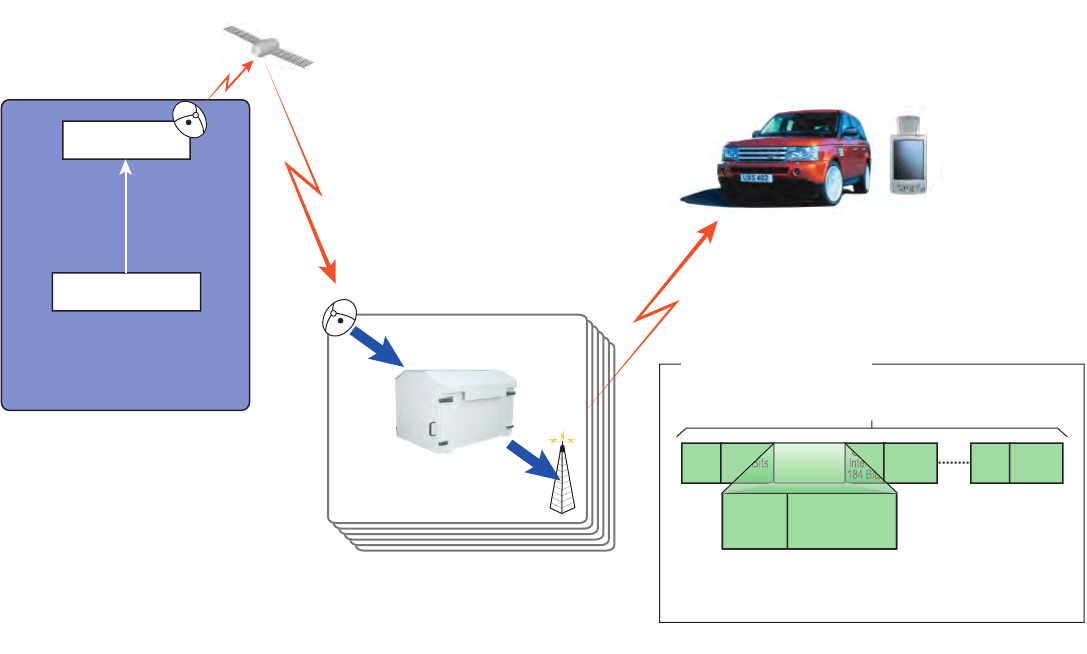
The Terrestrial Satellite Repeater is a modular solid-state device that receives audio/
video multiplexed data transmissions via a SIRIUS Satellite. The repeater then pro-
cesses the received
data and retransmits it through tower mounted antennas to end
users’
receivers.
Figure 1 - 1 is a simplified diagram of a SIRIUS Terrestrial Repeater broadcast system.
A repeater site (part of the broadcast system) includes a Very Small Aperture Termi-
nal (VSAT) antenna with a Low Noise Block converter (LNB) attached, a Global
Positioning System (GPS) antenna, a repeater unit, and tower mounted transmitting
antennas.
The repeater site interfaces to a SIRIUS Network Management Center (NMC) via
TELCO lines to monitor repeater operational status.
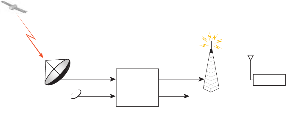
Figure 1 - 2
illustrates a typical repeater site layout.
Figure 1 - 1 Typical Sirius Terrestrial Repeater Broadcast System
CDDS
Over RS-422
Multiplex Source
VSAT Uplink
Studio
Intelsat 6 Ku Band
COFDM
Mobile Receivers
DTR-1000
02/22/07
Terrestrial Repeater
DVB-S
DVB-S2
Duration: 347.38 mSec
COFDM Clock Rate: 8.1921375 Mbaud
Terrestrial Broadcasting
COFDM Transmission Frame
Guard
Interval
184 Bits
2048 Bits
Guard
Interval
184 Bits
2048 Bits
Guard
Interval
184 Bits
2048 Bits
1275 Segments
Guard
Interval
184 Bits 2048 Bits
Genera
l
3EM21522AAAA
DTR-0200-SA-SIRIUS Issue 1, March 2008
1-2
Figure 1 - 2 Typical Sirius Terrestrial Repeater Site
1.2
REPEATER MAIN COMPONENT BREAKDOWN
The terrestrial repeater can be divided into the following main components:
• Signal Processing Unit (SPU)
• High Power Amplifier (HPA)
• Power Distribution Unit (PDU)
The cabinet also contains the following
• Output Band Pass Filter
• Output Coupler
Each of these components is addressed in the Functional Description section of this
manual.
CDDS Signal
From Satellite
VSAT + LNB
Antenna
COFDM RF Signal
To Customer
DTR-1001
02/22/07
REPEATER
TRANSMIT ANTENNA
Customer Equipment
GPS
Antenna PSTN
Alarms
to NMS
3EM21522AAAA Genera
l
Issue 1, March 2008 DTR-0200-SA-SIRIUS
1-3
1.3
REPEATER COMPOSITION
The repeater functional components comprise the following:
•HPA (located at the top level of the cabinet)
Power Amplifier
Module Pre-Driver
Splitter
Combiner
Power Supply
HPA Controller
• SPU (located at the middle level of the cabinet)
VSAT Receiver Module
Modulator Module
Main Controller Module
Up-Converter Module
Uninterruptible Power Supply (UPS)
• PDU (located t the bottom level of the cabinet)
Main power distribution source for the repeater
• Utility Compartment (shared with PDU)
Band Pass Filter
Output Coupler
Input/Output Junction Box
RF Detectors
The repeater cabinet contains hinged and lockable front and rear doors which provide
access to the internals of the repeater. The cabinet, designed to protect the repeater
internal components against adverse environmental conditions, is provided with ven-
tilating fans and heater units.
See
Figure 1 - 3
and
Figure 1 - 4
for front and rear views of the repeater cabinet.
Genera
l
3EM21522AAAA
DTR-0200-SA-SIRIUS Issue 1, March 2008
1-4
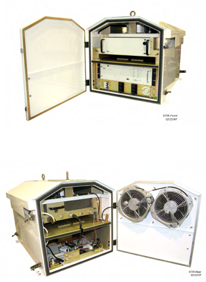
Figure 1 - 3 Front View of the Terrestrial Repeater
Figure 1 - 4 Rear View of the Terrestrial Repeater

3EM21522AAAA Genera
l
Issue 1, March 2008 DTR-0200-SA-SIRIUS
1-5
1.4
DIGITAL TERRESTRIAL REPEATER NAMING CONVENTION
DTR-0200-SA-SIRIUS
Mobile TV Standard
DVB-T/H DAB
DMB-S/T/H Eurika 147
ISDBT
FLO
CUST (Custom COFDM Waveform)
SIRIUS… Proprietary Signal
Method of Cooling
A = Air Cooled
L = Liquid Cooled
Frequency Band
V =
VHG Band III (174 to 230 MHz)
U = UHF (470 to 862 MHz)
L = L-Band (~1.4 to 1.7 GHz)
S = S-Band (~2.1 to 2.7 GHz)
Output Power in Watts
0200 = 200 Watts
1000 = 1000 Watts
Digital Terrestrial Repeater
DTR-1002
02/22/07

Genera
l
3EM21522AAAA
DTR-0200-SA-SIRIUS Issue 1, March 2008
1-6
1.5
SYSTEM CONFIGURATIONS
At the selected site the repeater can be mounted one of three ways:
• ground mount
• roof mount
• shelf mount
The repeater electrical and physical configuration is the same for either mounting.
1.6
TERRESTRIAL REPEATER TECHNICAL SPECIFICATIONS
Table 1-1 Physical, Electrical, and Environmental Specifications
Weight Approx. 121 kg (266 lbs.)
Dimensions 60.10 x 102.55 x 67.63 cm / 26.81 x 36 x
40.38 x 26.63 in.
Cooling Forced Air
Power Requirements 188-250VAC, 208 VAC NOMINAL, 57-63 HZ
Power Consumption 2.0 KW, TYPICAL
UPS Duration For Main Controller 5 minutes
Operating Temperature -25ºC to +55ºC / -13ºF to +131ºF
Storage Temperature -50ºC to +65ºC / -58ºF to +149ºF
Humidity 95% Non-condensing
Ratings/Circuit Breaker Max Effective Load/Circuit Breaker
CB1 – SPU: 240V, 5A – 1.20kW
@ MAX 55ºC Max current 0.75A
CB2 - HPA: 240V, 25A – 6.00 kW
@ MAX 55ºC Max current 12.5A
CB3 - FANS: 240V, 5A – 1.20 kW
@ MAX 55ºC4 fans, 80W each – 320W total
Max. current 1.5A
CB4 - EXTERNAL
HEATER: 120V, 5A – 0.240 kW
@ MAX 55ºCMax. power 200W
Max. current 1.7A
CB5 - AUXILIARY
POWER: 120V, 10A – 0.600
kW @ MAX 55ºC Max. current 5A
CB6 – INTERNAL
HEATER: 240V, 5A – 1.20 kW
@ MAX 55ºC2 Heaters 500W (nominal)
Max total. current @ 240VAC, 4.2A
CB0 – MAIN
CIRCUIT BREAKER: LINE 1 - 240V, 32A
@ MAX 55ºC
LINE 2 - 240V, 32A
@ MAX 55ºC
NEUTRAL - 32A
@ MAX 55ºC
Max. load per Line and Neutral:
LINE 1: Max current 25.7A
LINE 2: Max current 19A
NEUTRAL: Max current 6.7A

3EM21522AAAA Genera
l
Issue 1, March 2008 DTR-0200-SA-SIRIUS
1-7
Table 1-2 Transmitter RF Output Performance
Operating Frequency 2326.25 MHz
Bandwidth 4.012 MHz
Rated Output Power +53.0 dBm
Output Power Set Point Range 10 dB
Step Size 0.5 dB
Output Level Stability vs. Time ≤ -0.25 dB/24 hrs. max
Output Level Accuracy ≤ ±0.5 dB about selected level (+47 to +53 dBm range)
Spectral Re-growth See Note 1 and Note 2
In-Band Carrier to Intermodulation Ratio >25 dB
Spurious Level Outside Channel < -60 dBm
Amplitude Flatness Center Frequency ±2.006 MHz, ±0.5 dB
Connector Type 7/16'' DIN, female, 50 ohm
Output VSWR ≤ 1.3:1
Note 1:The total RMS power in a bandwidth of 4.20 MHz centered around 2322.255 MHz, measured at
the input to the antenna/cable system, is better than 40 dB down with respect to the RMS power in the
transmitter COFDM signal measured at the same reference point.
Note 2:The total RMS power in a bandwidth of 4.20 MHz centered around 2330.245 MHz, measured at
the input to the antenna/cable system, is better than 40 dB down with respect to the RMS power in the
transmitter COFDM signal measured at the same reference point.
Table 1-3 Control Interfaces
NOC Interface
Connector RJ11
Standard V90
Protocol SNMP, WEB Interface
Ethernet Interface
Connector RJ45, 10/100/1000 Base T
Protocol SNMP, WEB Interface
RS 232
Connector DB9 (M)
Protocol Local Console Interface
GPS Antenna
Connector N-Type, female, 50 ohms, with bias voltage

Genera
l
3EM21522AAAA
DTR-0200-SA-SIRIUS Issue 1, March 2008
1-8
Table 1-4 Repeater Signal Inputs
VSAT Ku Band (L-Band after LNB)
Frequency Range 950 – 2150 MHz
Nominal Input Level -65 to -25 dBm
Waveform S1, S2
LNB Bias Provided
Connector F-type, female, 75 ohms
Ethernet Input
Signal IP multicast, standard 10/100 Base T interface
Connector RJ45
ASI Input
Connector BNC, 75 ohms
Table 1-5 Signal Processing
Aggregate Data Rate 7.340625 Mbps
COFDM nominal bandwidth used 4.012 MHz
Modulation Type Pi/4 Differential QPSK with adjustable amplitude
and phase offset for hierarchical modulation
Number of Active Carriers 1000 (+2 unmodulated pilots +1 central null)
Intercarrier Spacing 4 kHz
FFT Size 2048 points (2 times oversampling)
COFDM Sampling Rate (1/T_COFDM) 4.096 MHz (with no oversampling)
COFDM FFT Rate (1/T_FFT) 3.6703125 kHz
Total Symbol Duration 272.4564 us
Useful Symbol Duration 250 us
Guard Interval 22.4564 us
COFDM Demodulator Output Symbol Rate (1/Ts) 3.6703125 Mbaud QPSK
Time and Clock Reference Internal GPS
Phase Noise SSB 100Hz: < -72 dBc/Hz
1kHz: < -77 dBc/Hz
4kHz < -81 dBc/Hz
10kHz: < -84 dBc/Hz
100kHz: < -112 dBc/Hz
1MHz: < -123 dBc/Hz
Sirius Transmission Frame Buffering (terrestrial
signal time delay) Up to 17 frames (approx. 6 sec.)

3EM21522AAAA Genera
l
Issue 1, March 2008 DTR-0200-SA-SIRIUS
1-9
1.7
REPEATER COMPONENTS LOCATION
The repeater enclosure cabinet contains field replaceable subassemblies called “Least
Replaceable Units (LRUs)” as listed in Table 1-8.
Figure 1 - 5
locates the repeater components including the LRUs.
The part number for the entire repeater enclosure cabinet with all electronics and
internal equipment is P/N 3EM04000AA.
Table 1-6 Repeater Test Ports
Repeater Out Forward Power Connector: N-type, female, 50 ohms, Coupling: -50 dB
Repeater Out Reflected Power Connector: N-type, female, 50 ohms, Coupling: -40 dB
HPA RF Monitor Connector: N-type, female, 50 ohms, Coupling: -50 dB
Upconverter RF Out Monitor Connector: SMA, female, 50 ohms, Coupling: -20 dB
Table 1-7 Repeater Test Modes
CW Signal COFDM spectrum replaced by a single carrier 4kHz aside from the
center frequency. The RMS level of the single carrier is equivalent to
average RMS level of normal COFDM spectrum. The signal is
intended for testing of in-band signal-to-noise ratio.
Notch Signal Movable group-of-carriers hole for test of intermodulation and quanti-
zation noise
PRBS Signal Empty DARS frames (PRBS sequence)
Table 1-8 Repeater Least Replaceable Units (LRUs)
Signal Processing Unit (SPU)
Refer to Appendix B
for part numbers
High Power Amplifier (HPA)
RF Output Coupler
RF Detector (Two; one forward, one reflected)
Cabinet Exhaust Fan (two exhaust fans under roof)
Cabinet Exhaust Fan Relay
Cabinet Intake Fan (two intake fans in rear door)
Cabinet Intake Fan Relay
PDU Circuit Breakers
Genera
l
3EM21522AAAA
DTR-0200-SA-SIRIUS Issue 1, March 2008
1-10
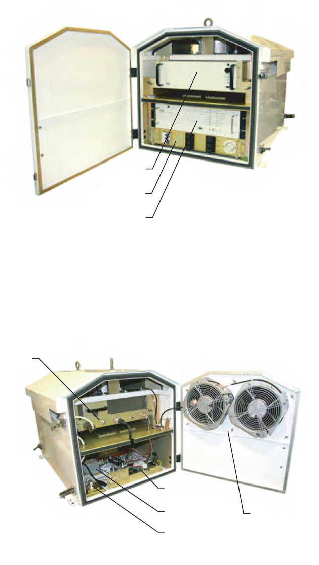
Figure 1 - 5 Components Location (Sheet 1 of 2)
Figure 1 - 5 Components Location (Sheet 2 of 2)
DTR-1074
07/30/07
Front View
PDU
SPU
HPA
DTR-1075
07/30/07
Rear View
RF Coupler
and Detectors
BP Filter Filter Assembly
(inside of door)
Junction
Box
HPA
3EM21522AAAA Functiona
l
Description
Issue 1, March 2008 DTR-0200-SA-SIRIUS
2-1
2FUNCTIONAL DESCRIPTION
2.1
GENERAL
This section presents a functional description of the Sirius Terrestrial Repeater.
2.2
SYSTEM FUNCTIONAL OVERVIEW
Figure 2 - 1
shows the basic Repeater Simplified Functional Block Diagram.
The Sirius Terrestrial Repeater transmits at the 2.3265 GHz frequency with a 4.012
MHz signal bandwidth. Refer to the tables in Section 1 for the technical characteris-
tics and the major components.
2.2.1
SIGNAL FLOW
The Sirius Terrestrial Repeater receives the video/audio Complex Digital Data
Stream (CDDS) signal in a TDM format at the KuBand from the satellite by means
of a Very Small Aperture Terminal (VSAT) parabolic antenna.
The CDDS signal passes through a Low Noise Block (LNB) converter to the DVB-S
L-Band satellite receiver; an integral part of the Signal Processing Unit (SPU). The
satellite receiver demodulates the incoming stream and outputs the processed data
via the Asynchronous serial Interface (ASI) to the SIRIUS modulator stage.
The output of the modulator is an Orthogonal Frequency Division Multiplexed IF
(I and Q signals).
The IF is up-converted to an S-band frequency for insertion into the High Power
Amplifier (HPA). The output of the HPA goes through the output bandpass filter
(BPF) where “out of band” generated signals are removed.
The output BPF signal (200W RF) goes through the output RF coupler to the tower
mounted antennas and is transmitted to the end user
2-2 This page intentionally left blank.
2
-
3
Figure 2 - 1 Repeater Simplified Functional Block Diagram
DTR-1008
03/04/08
DVB-S/S2
Receiver
Power Distribution
Unit
(with breakers)
Relay
Group
Ext
Heater
Aux 115V AC
Fans/Temperature Sensors/
Contactors
SPU Compartment
Heater
Modulator
IF I
IF Q
RF Test
SMA-F
RF Fwd Test
N (F)
RF Refl Test
N (F)
RF Out (200W)
To Antenna
IF Test I & Q
BNC 50 Ohm
VSAT
ASI
Local CLI (serial)
DB8
POTS
Up-Converter Control
HPA Control
Output Power Level Control
208V AC
Main Controller
Board
Main
Controller Supervisor
Processor
Modulator Control
Internal UPS
GPS
Receiver
Ethernet
Switch
Dial-up
Modem
Control
Core Up-
Converter BPF
Output
Coupier
RF
Fwd RF
Fwd
HPA
DSP
Core
208V AC
HPA
Compartment
Utility
Compartment
SPU
Repeater Cabinet
L
N
B
GPS
F Type
N(F)
Local Ethernet
RJ-45
Local CLI (serial)
DB-9
RJ-11
Power
Supply
7-16 DIN (F)
2-4
This page intentionally left blank.
3EM21522AAAA Functiona
l
Description
Issue 1, March 2008 DTR-0200-SA-SIRIUS
2-5
2.3
MAIN FUNCTIONS
The Sirius Terrestrial Repeater consists of the following main functions:
•
Receiver
– Receives the down converted input signal from the VSAT Antenna/
LBN via coax cable. Processes the received signal for transmission to the modula-
tor.
•
Transmitter
– (modulator, up converter, HPA, bandpass filter, and output
coupler) Transmits the received and processed RF signal, via tower mounted
antenna, to the end user’s equipment.
•
Timing
– A GPS receiver provides signals for synchronization within the Signal
Processing Unit (SPU).
•
Monitor and Control
– This function is primarily performed by the main con-
troller board which receives information from all external devices, including
temperature, power to antenna, output signal control parameters, and equipment
condition.
•
Power Distribution
– Power is controlled and distributed by a power distribu-
tion unit (PDU) and a relay control group.
Functional description of the components involved in these main functions follows.
2.3.1
SIGNAL PROCESSING UNIT (SPU) SUB-ASSEMBLY
Figure 2 - 2
and
Figure 2 - 3
respectively show a physical representation and functional
block diagram of the SPU.
The primary function of the SPU is to receive the complex digital data stream
(CDDS) from the VSAT satellite, modulate the received signal into a COFDM wave-
form, up-convert the waveform to the assigned S-Band frequency within the user’s
frequency plan, and forward this waveform to the HPA in the transmitter portion of
the repeater.
The SPU contains the L-Band satellite receiver, modulator, up-converter, main con-
troller, and Uninterruptible Power Supply (UPS).

Functiona
l
Description 3EM21522AAAA
DTR-0200-SA-SIRIUS Issue 1, March 2008
2-6
Figure 2 - 2 Signal Processing Unit (SPU)
2
-
7
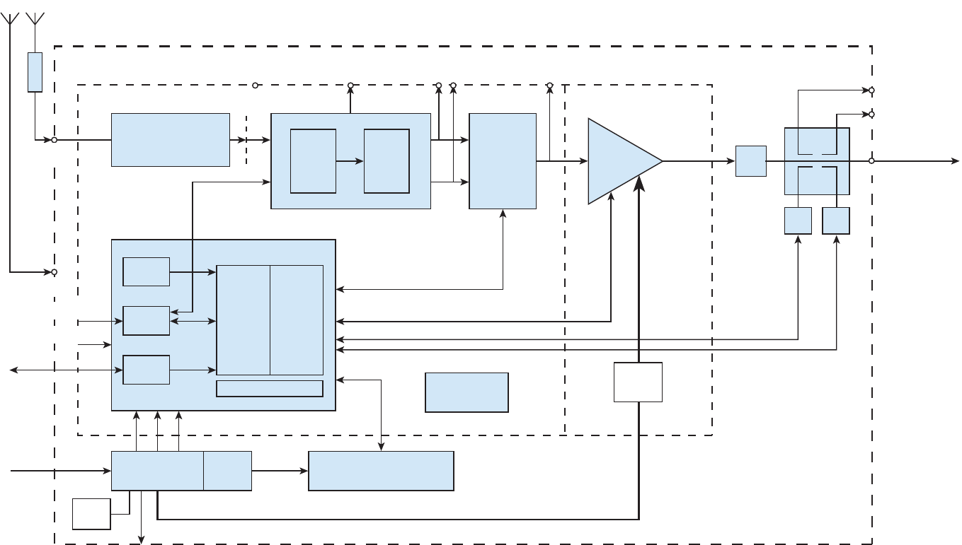
Figure 2 - 3 Sirius Signal Processing Unit (SPU) Functional Block Diagram
2-8
This page intentionally left blank.

3EM21522AAAA Functiona
l
Description
Issue 1, March 2008 DTR-0200-SA-SIRIUS
2-9
2.3.1.1
L-Band (VSAT) Receiver
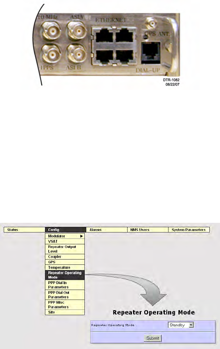
The VSAT L-Band receiver connector panel is shown in Figure 2-4.
The receiver module is located on the SPU sub-assembly.
The module receives the DVB-S/S2 signal data stream (which carries the SIRIUS
proprietary CDDS) from the L-band LNB module located on the Ku-band VSAT
antenna.
The receiver processes the down-converted L-band signal by DVB-S/S2 transport
stream removal and data recovery
.
The final receiver output is a stream of CDDS encapsulated into pseudo MPEG TS
packets.
Figure 2 - 4 VSAT (L-Band) Receiver Panel
2.3.1.2
Modulator
The modulator panel is shown in
Figure 2 - 5
.
The modulator, located on the SPU sub-assembly, converts the digital coded stream
to an IF.
It receives Sirius CDDS stream input data from the L-band receiver in the form of
MPEG TS packets transferred by DVB-ASI.
The modulator also receives reference system clock signals in the form of 10MHz and
1PPs from the GPS distribution amplifiers. These clock signals enter the modulator
at J17A and J17B and synchronize the modulator clock and, in turn, the modulator
output.
COFDM converts the MPEG TS frames to an IF in the form of I and Q signals with a
center frequency of 76.25 MHz ready for up conversion.
The modulator contains a DB-9 serial port wired as a DTE device and requires a null
modem cable to communicate with the serial port on a PC.
Functiona
l
Description 3EM21522AAAA
DTR-0200-SA-SIRIUS Issue 1, March 2008
2-10
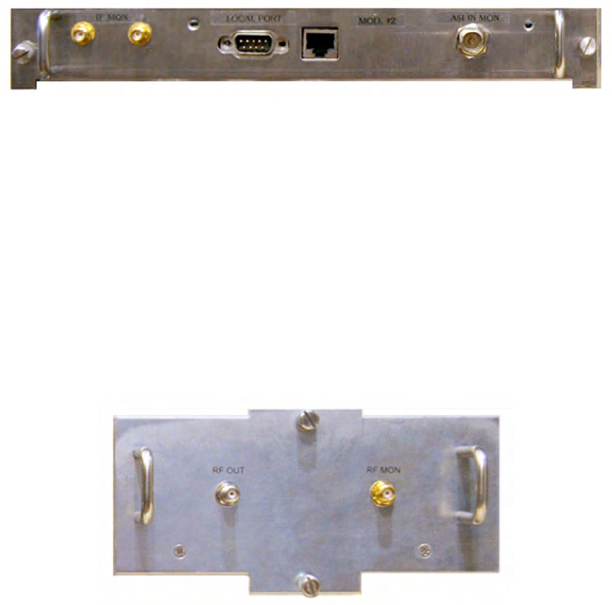
Figure 2 - 5 Modulator Module
2.3.1.3
Up-Converter
Figure 2 - 6 shows the up-converter panel. The up-converter converts the modulator
IF (I and Q channels) output to S-Band.
An up converter controller applies DAC-controlled DC offset to each IF channel,
attenuates and filters the channels, and then sends them to the up-converter for
S-Band frequency con-version.
The 2.32625 GHz S-Band output of the up-converter feeds into the pre-driver of the
HPA.
Figure 2 - 6 Up-Converter Module Panel
2.3.1.4
SPU Main Controller Board
See Figure 2 - 7 and Figure 2 - 8 connector panel and functional block diagram.
The main controller supports the repeater site operation, configuration, manage-
ment, and status reporting. It manages power-up, power-down and RF control pro-
cesses. The controller provides capability for remote upgrade of repeater software,
and provides local and remote interfacing for all command and status functions
(including digital, thermal, power, and RF performance of the repeater).
3EM21522AAAA Functiona
l
Description
Issue 1, March 2008 DTR-0200-SA-SIRIUS
2-11
Control commands for status requests and operating parameter modifications from
the operator interfaces are received and processed by the main controller.
The controller reports problem conditions through dedicated interfaces and also indi-
cates current status and alarms via front panel LEDs.
Repeater identity can be configured remotely or locally via the controller. Configura-
tion includes repeater identity (repeater name, password, local IP address, two
remote NMS IP addresses, and SNMP security variables).
The functional software components of the controller are:
• Repeater protection via continuous local monitoring of all main blocks.
The output coupler, HPA, and HPA power supply are continually monitored. If any
monitored parameter exceeds its threshold, the RF is shut down and the Network
Management Center (NMC) is notified. Hazardous conditions shut down the
repeater. Under certain conditions clearing the event will automatically restart the
repeater.
• HPA RF output Automatic Power Level Control (APLC).
The APLC loop checks RF output level reported by the RF output coupler and
changes the up converter out-put level.
• Performance of two-way communication with the NMC.
Communication can be via either of the following:
Dial-up modem through a PSTN line
Ethernet to the Management Center via WAN
Forward channel using the input channel and satellite return channel.
• Load, initialize, and monitor the supervisor controller, the GPS receiver, the up
converter, the VSAT receiver, the modem, and the modulator.
• Perform software upgrade for the main controller, supervisor controller, and mod-
ulator.
• Monitor RF subsystems; HPA, HPA power supply, and RF coupler
• Event Logging is written to the EEPROM and accessible from WEB/embedded
FTP server via NMC.
• Self monitoring and environment monitoring (temperature, fans, voltage, cur-
rent)
Power-up Test
– on power-up the main controller performs a self-test (POST) and
waits for all other subsystems to perform POST of their major components and
report results. Any main block problem causes the repeater to shut down and an
attempt is made to notify the NMC. Notification is attempted via the modem or
Ethernet to the NMC.
Functiona
l
Description 3EM21522AAAA
DTR-0200-SA-SIRIUS Issue 1, March 2008
2-12
Back-up Test
– continuous self-monitoring of controller and all subsystems. Anoma-
lies are reported to NMC. Major faults cause the controller to shut down the repeater
Heartbeat
– a special trap/message is transmitted regularly (transmission inter-val
set by user via GUI, See Figure 5-34 in Section 5) to the NMC. This message indi-
cates to the NMC operator that the repeater is alive; a valid connection exists
between the repeater and the NMC, and the repeater main controller is operational.
• Local/remote software upgrade – software upgrade is initiated via a web browser
by directly uploading the upgrade file to the controller. When the file is success-
fully received, the web server task will invoke the upgrade procedure. Upgrade
applies to any of the controller software components or any of the other system
components.
• Parameter database clearing in EEPROM will return to default settings.
The functional physical components of the controller are:
• Main Controller microprocessor chip MPC860x
• Supervisor Processor microprocessor chip ATmega2560
• GPS receiver
• Dial-up modem
• Ethernet Switch
• Internal UPS
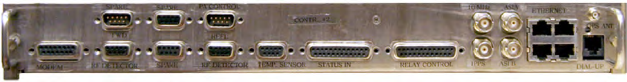
Figure 2 - 7 Controller Board Panel
3EM21522AAAA Functiona
l
Description
Issue 1, March 2008 DTR-0200-SA-SIRIUS
2-13
Figure 2 - 8 Main Controller Board Functional Block Diagram
Functiona
l
Description 3EM21522AAAA
DTR-0200-SA-SIRIUS Issue 1, March 2008
2-14
2.3.1.4.1
Main Controller Microprocessor Chip
The MPC860 microprocessor performs all site management to include control of the
GPS receiver, modem, and L-band DVB-S/S2 receiver. The controller also communi-
cates with the SPU modules and on-board components via dedicated interfaces using
soft-ware defined protocols. The MPC860 chip connects to the Ethernet, to an exter-
nal monitoring/controlling console (PC), to the VSAT receiver, the internal modem, to
the upconverter, to the power amplifier, and to the following front panel components:
the status LED, the Local/Remote switch, and the Reset switch. The MPC860 also
connects, via the module internal I2C bus, to the ATmega256 control processor
(supervisor controller).
• Ethernet connection-via an internal Ethernet controller connected to an internal
Ethernet switch and terminating at four RJ-45 connectors (J115A, J115B, J115C,
and J115D). External Console connection via a UART (UART0) internal to the
MPC860 chip and connected to module internal connector J129 (DB9-F).
• VSAT Receiver- connects to the MPC860 chip via the module internal I2C bus
and internal connector J129.
• Internal Modem connection-from UART2 in the MPC860 chip to the modem and
then to the RJ-11 connector at J119.
• The Upconverter-connected to the MPC860 chip via the module internal I2C bus.
• Power Amplifier connection-to the MPC860 chip via RS485 bus. This is a full
duplex PA control line.
• Front panel components-the status LED, the Local/Remote switch, and the Reset
switch connect to the J129 internal connector on to the I_C bus and into the main
processor chip.
2.3.1.4.2
Supervisor or Control Processor
The ATmega256 chip monitors status, temperature, and RF power. The chip also con-
trols output digital relays required for interface with the external equipment.
• Relay Control – The ATmeg a256 connects to the Relay Control Group via back
panel DB25 connector P18 for fan control (four channels).
• Fan Speed & Door Monitoring – The processor connects to DB25 back panel con-
nector P17A to receive digital inputs (up to 12 lines). Four channels are for fan
speed monitoring, and two for front and back door monitoring. Six additional
switches can be connected as required.
• Temperature Sensing – There are three temperature sensing thermistors (ambi-
ent, HPA compartment and SPU) connected to terminal board 3 (TB3). The pro-
cessor provides +5 VDC to each thermistor and reads the temperature from -55˚C
to + 180˚C of each thermistor. The TB3 connections to the processor are via DB9-
F panel connector P7B.
3EM21522AAAA Functiona
l
Description
Issue 1, March 2008 DTR-0200-SA-SIRIUS
2-15
•RF Power: Monitoring is two channel and RS485 full duplex. The path is from the
reflected power and forward power detectors through DB9-M panel connector
P6B into the processors UART1 and UART2. The Atmega256 processor initial-
izes the GPS Receiver, makes all necessary settings and then monitors important
stats (refer to GPS Receiver below).
2.3.1.4.3
GPS Receiver
The GPS receiver provides 10 MHz and 1 pps signals for synchronization purposes.
The signals’ exact alignment to a UTC/GPS second is monitored via a message
received by the controller as a response to the correspondent’s request. The receiver
supports proprietary binary messages and also NMEA formatted message protocol.
A subset of the protocols is used by the MPC860 microprocessor to control receiver
operation. After initialization, the GPS starts tracking the satellites to determine its
position; the accuracy of the GPS output signals depends on the GPS satellite recep-
tion. The Controller communicates continuously with the GPS to deter-mine if the
GPS is still operating correctly and still receiving the satellite signals, etc., or if it
has any alarm (malfunction) to report. The output of the GPS (1 pps and 10MHz
pulses) is to the Distribution Amplifiers, which in turn feed the pulses to the Modula-
tor and Up-converter via internal connector J130.
2.3.1.4.4
Dial-up Modem
Two chips, Si2457 and Si3018, make up an internal modem and provide the required
connectivity to POTS (PSTN). The phone line connection is via an RJ11connector
(J119 on the front panel). This telephone communication channel provides the main
control interface for repeater monitoring by the Sirius repeater NMS. Information
exchange between site and NMS is via SNMP.
2.3.1.4.5
Ethernet Switch
The Ethernet switch is a built-in 10/100 Base-T switch and provides four RJ-45
Ethernet ports allowing the controller to communicate with other Ethernet devices.
2.3.1.4.6
Uninterruptible Power Supply (UPS)
See
Figure 2 - 9
. The UPS monitors the AC line status and if the AC voltage drops, it
provides +5V and +3.3V for CPU backup. The UPS provides CPU back-up power for
up to 5 minutes, enough time to store the current state of the repeater, store param-
eters in volatile memory, notify NMS, and completely and safely shut down the
repeater. The unit comprises a bank of five Ultra Capacitors, 350F/2.5V each, a DC/
DC converter, over-voltage protection and charging/discharging circuitry. During
repeater power-up, the capacitors charge through a current limiting resistor with
the bulk of the power going to the SPU and no interruption of power during this
period. When power is interrupted, the capacitors discharge to the load through the
DC/DC converter at a steady five volts until they reach approximately seven volts at
which time the SPU power is terminated.
Functiona
l
Description 3EM21522AAAA
DTR-0200-SA-SIRIUS Issue 1, March 2008
2-16
A manual ON/OFF control switch is located on the front panel of the UPS and
allows the unit to be manually switched on or off. This is used primarily by mainte-
nance technicians when servicing the repeater.
An internal automatic ON/OFF switch switches the unit off when the +5 or 3.3
input voltages drop. This prevents back current feed to the power supply. The UPS
has a 3-wire interface for connection of an optocoupled AC sensor.
Figure 2 - 9 Uninterruptible Power Supply (UPS)
2.3.1.4.7
SPU Power Supply
The power supply is 208VAC, 30-50 W brick power supply AC/DC converter and pro-
vides all required voltages for the SPU:
+5V @ 3A
+3.3V@1A
+12V@2A
-12V@0.5A
+24V@1A
The power supply input is 208VAC/50-60 Hz.
2.3.1.4.8
SPU Compartment Heater
The SPU compartment heater protects the SPU enclosure from freezing and/or con-
densation.
3EM21522AAAA Functiona
l
Description
Issue 1, March 2008 DTR-0200-SA-SIRIUS
2-17
2.4
HIGH POWER AMPLIFIER (HPA)
See
Figure 2 - 10
and
Figure 2 - 11
for the HPA sub-assembly front and rear panels and
the HPA functional block diagram.
The HPA amplifies the S-Band terrestrial signal to an output level of 200 watts
(after the output filter). The HPA is a solid-state device operating in Class A/B linear
mode over a frequency range of 2305 MHz to 2360 MHz and is fully protected against
input overdrive, temperature, and output load VSWR conditions. The protection cir-
cuitry is self-correcting and allows restoration of the HPA to normal operation upon
removal of the fault.
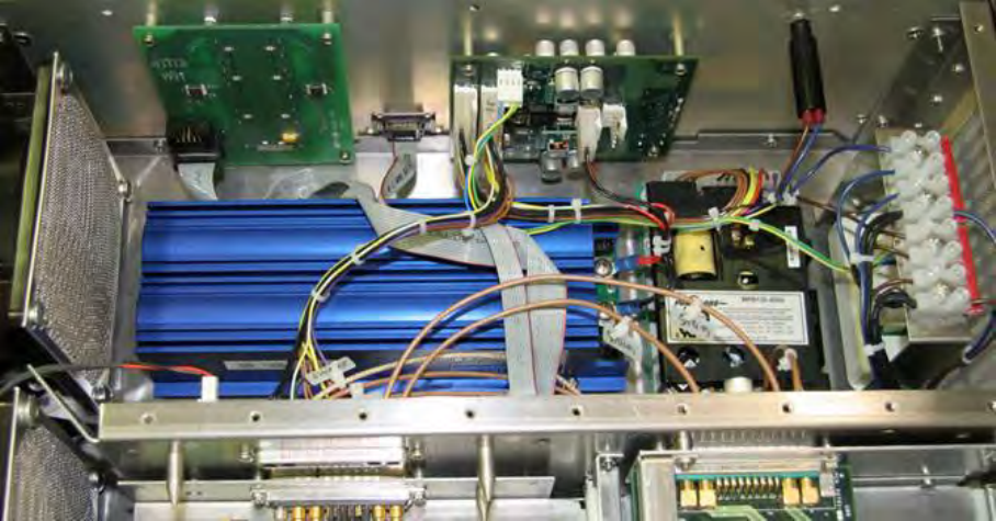
The HPA is a separate sub-assembly Least Replaceable Unit (LRU) installed on slid-
ing rails in the repeater enclosure. It contains an integrated AC/DC power supply, a
pre--driver, a driver, a 5-way splitter, five individual power amplifier modules, a 5-
way combiner, and an HPA controller.
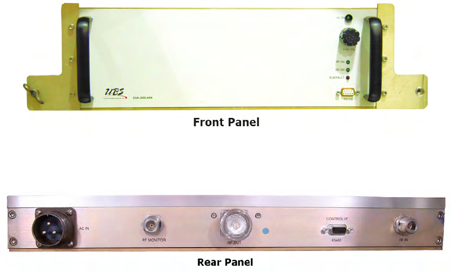
Figure 2 - 10 HPA Panels
Functiona
l
Description 3EM21522AAAA
DTR-0200-SA-SIRIUS Issue 1, March 2008
2-18
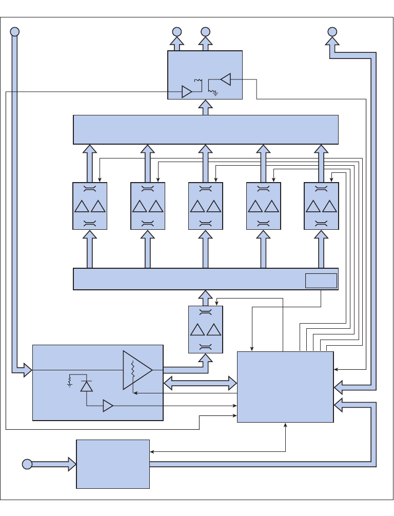
Figure 2 - 11 HPA Functional Block Diagram
RF Output
Coupler
J1
RF INPUT J3
RF OUTPUT J4
CONTROL
J2
FWR PWR
MONITOR
50dB
5-WAY OUTPUT COMBINER
SIRIUS HPA BLOCK DIAGRAM
40dB
50dB
DTR-1013
03/10/07
Output Pwr
DC BIAS OUT
DC & CONTROL RS422
DC IN
DC IN
HPA
CONTROLLER
Preamplifier
Power Supply
Temperature
Sensing
J5
AC INPUT
Monitor
Output Pwr
Monitor &
Control
3-WAY SPLITTER
20dB
3EM21522AAAA Functiona
l
Description
Issue 1, March 2008 DTR-0200-SA-SIRIUS
2-19
2.4.1
HPA CONTROLLER
The HPA Controller monitors various parameters and reports current values and
summary alarms to the repeater main controller via the RS485 interface. The vari-
ous monitored parameters and statuses are the power modules working conditions
(DC voltages and currents), the temperature inside the HPA assembly, the HPA for-
ward and reflected power levels, input power and gain, RF power inhibit, HPA power
supply enabled/disabled, input/output overdrive alarm, over-temp alarm (announced
prior to shut-down), over-temp fault, HPA shut-down alarm, output device failure
alarm, driver device failure alarm, HPA low gain alarm, power supply AC fault, and
power supply DC fault.
The HPA Controller also performs HPA pre-driver control, provides the HPA power-
up and shut-down procedure, and interfaces the HPA to the host (SPU Main Control-
ler). If the HPA controller detects a problem with a specific PA module, it shuts down
the entire HPA. The SPU main controller can restart the HPA utilizing the remain-
ing operational PAs. If the number of faulty PAs exceeds a predetermined threshold,
the HPA can not be restarted by the host.
Since the HPA is a constant gain block, it is individually calibrated to maintain RF
performance under varying operating conditions. Calibration is performed on the
forward, reflected, and input power sensors. A calibration table dependent on tem-
perature and frequency is stored in the internal EEPROM of the HPA controller.
The HPA controller reports alarms to the main controller and maintains a log of
alarms. Alarm entries contain the alarm ID and monitored parameters prior to
alarm activation. The alarm log is stored in an internal EEPROM. The HPA control-
ler can enable/disable the output RF and also turn the integrated power supply DC
power ON and OFF.
2.4.2
HPA POWER SUPPLY
The HPA Power Supply is a high performance power source that delivers appropri-
ate voltages and current necessary to operate the HPA at its required performance
level. The power supply resides in a separate compartment inside the HPA module
and employs four independent AC-to-DC converters operating in parallel. The con-
verters’ outputs are combined on a single bus and connect to the input terminal of
the Power Distribution/Controller board located in the power supply compartment.
The Power Supply contains supervisory circuitry to report the status of the AC input
voltage and DC/DC converters operation status to the Power Distribution/Controller
module. This Controller module also monitors the Power Supply DC output voltage
and the current draw of each of the HPA sub-modules, and reports these parameters
back to the Main System Controller via the serial port. In addition, the Power Sup-
ply has the ability to enable/disable the power to the HPA when so commanded by
the Main System Controller.
Functiona
l
Description 3EM21522AAAA
DTR-0200-SA-SIRIUS Issue 1, March 2008
2-20
2.4.3
HPA PREAMPLIFIER (PREDRIVER)
The pre-driver is the first amplifying stage of the HPA. It employs three stages of
amplification-a Monolithic Microwave Integrated Circuit (MMIC) amplifier and two
LDMOS transistors. The pre-driver raises the output power of the RF from the up-
converter by 38 dB and feeds the amplified RF into the HPA driver amplifier. The RF
signal from the pre-driver input is also coupled to the RF detector circuit which pro-
vides detected RF to the HPA controller for monitoring and gain control. The coupled
RF signal is routed through a PIN diode attenuator to maintain the HPA gain con-
trol loop. The pre-driver amplifier, via a Gallium Arsenide (GaAs) MMIC RF switch,
can turn the RF signal on or off by way of a logic level HIGH RF Shutdown TTL con-
trol signal.
2.4.4
HPA DRIVER AMPLIFIER
The driver amplifier, employing two parallel amplifiers, receives the RF output from
the pre-driver and amplifies it by 13.3 dB. The output of the driver amplifier is fed
into a five-way splitter at a power level of 43 dBm.
2.4.5
HPA POWER SPLITTER
The five-way power splitter is connects directly to the HPA driver amplifier RF out-
put. The splitter evenly distributes this RF power to the five individual output power
amplifier modules.
2.4.6
POWER AMPLIFIER MODULES
The five power amplifier modules are identical to the driver amplifier module. These
modules are paralleled and receive equal inputs from the five-way power splitter.
The amplifiers each contribute a gain of 13.3 dB to their respective input, the five-
way combiner/coupler.
2.4.7
COMBINER/COUPLER
The five RF power amplifier outputs are combined into one via a zero-degree star
combiner. Two stripline couplers provide output signal sampling. One coupler’s out-
puts are terminated with SMA connectors and are used to provide external forward
and reflected RF monitoring ports. The other coupler’s outputs are detected using
true-type RF detectors installed on a coupler printed circuit board. These detected
signals are fed to the HPA Controller for control and monitoring purposes. The
detected signals and DC power for the on-board detectors are routed through 6-pin
Molex connectors installed on a coupler board. The 5-way combiner/coupler requires
external +5VDC ± 0.5 volts. When the combiner/coupler is installed on the HPA chas-
sis, the inputs are connected directly to the power modules’ output pins. The output
of the combiner is connected to the central conductor of the HPA output connector.
3EM21522AAAA Functiona
l
Description
Issue 1, March 2008 DTR-0200-SA-SIRIUS
2-21
2.5
S-BAND OUTPUT FILTER
The output filter is a bandpass filter and provides attenuation of the out-of-band
emissions generated by the HPA. The attenuation is to comply with the require-
ments of TN-SPEC-2.1.0, Terrestrial Network Technical Specification, Transmitter
RF Emissions.
2.6
OUTPUT COUPLER
The output coupler, connected to the output port of the transmit filter, is the final
component in the transmitter chain. The coupler samples the composite RF power
level at the repeater RF output. The RF levels at the FWD and REF ports are mea-
sured with the RF detectors and reported to the repeater main controller via the
RS485 interface. The output coupler provides test ports for connection to external
test equipment.
2.7
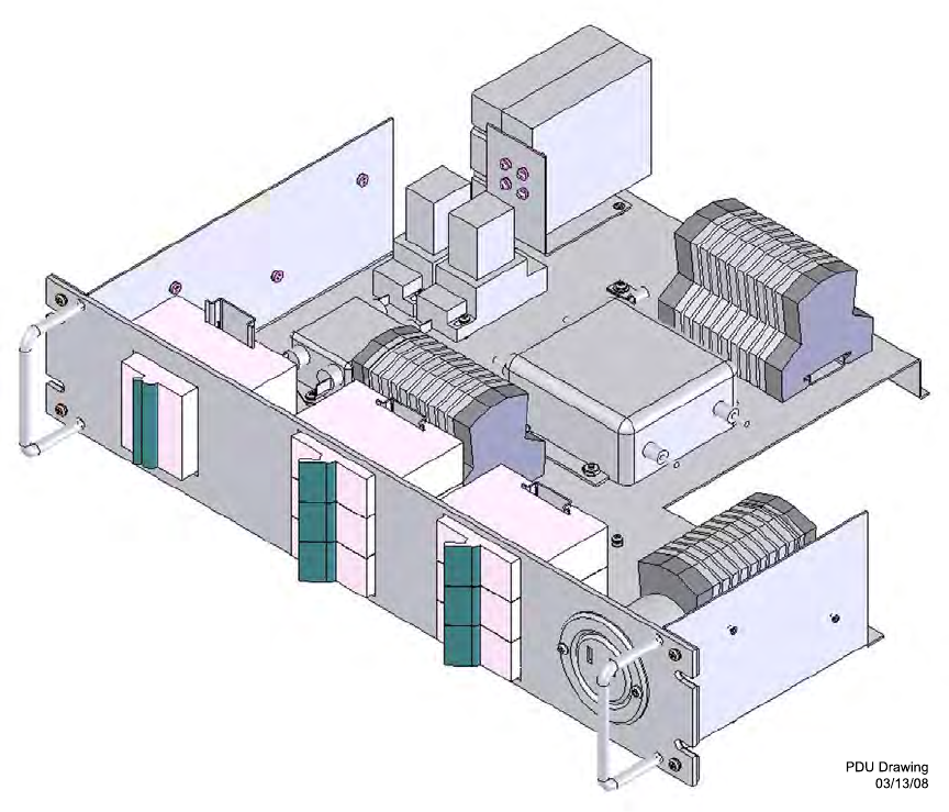
POWER DISTRIBUTION
See
Figure 2 - 12
and
Figure 2 - 13
for a simplified block diagram and an isometric view
of the Power Distribution Unit (PDU). The PDU is mounted on the bottom of the
repeater cabinet (see
Figure 1 - 5
), receives the input commercial 208VAC power, and
distributes required power to the repeater modules.
The PDU is comprised of seven circuit breakers, two surge protectors, two RFI power
line filters, two latching relays, forty two-stage feed through terminal blocks, and one
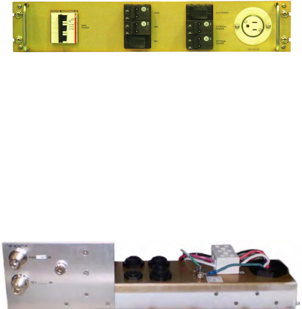
double grounding terminal. The front panel of the PDU houses the seven circuit
breakers and one power outlet.
The circuit breakers are as follows:
MAIN POWER – one 32A, 250VAC, 3-pole circuit breaker controls the incoming
208VAC to the repeater from the commercial source. Throwing this breaker will
remove all power from the repeater.
FANS – one 5A, 250VAC, 2-pole breaker powers the axial fans.
HPA – one 25A, 250VAC, 2-pole breaker supplies the HPA power supply. SPU – one
5A, 250VAC, 2-pole breaker supplies the SPU power supply
EXT HEATER – one 5A, 250VAC, 2-pole breaker powers the external heater
INT HEATER – one 5A, 250VAC, 2-pole breaker powers the internal heater
AUX POWER – one 10A, 250VAC, 2-pole breaker supplies 120VAC, 5A, to the AUX
OUTLET
.

Functiona
l
Description 3EM21522AAAA
DTR-0200-SA-SIRIUS Issue 1, March 2008
2-22
Figure 2 - 12 Simplified Block Diagram of Main Power Paths
HPA POWER SUPPLY
AUX PWR
AUX OUTLET
EXT HTR
INT HTR
FANS
HPA
VSAT RX
UPS
SPU
MAIN PWR
MODULATOR
MAIN CONTROLLER
UP-CONVERTER
DTR-1009
03/06/07
3EM21522AAAA Functiona
l
Description
Issue 1, March 2008 DTR-0200-SA-SIRIUS
2-23
Figure 2 - 13 Power Distribution Unit (Sheet 1 of 2)
Functiona
l
Description 3EM21522AAAA
DTR-0200-SA-SIRIUS Issue 1, March 2008
2-24
Figure 2 - 13 Power Distribution Unit (Sheet 2 of 2)
2.8
JUNCTION BOX ASSEMBLY
The junction box is mounted on the floor of the cabinet just behind the rear door.
It is the interface for the external connections for the AC power line, the VSAT
antenna, the GPS antenna, and the telephone line. It also houses the input power
(208VAC) terminal block, lightning protectors for the VSAT receiver and GPS
receiver, and the cable glands for Ethernet and telephone cables.
Figure 2 - 14 Junction Box Assembly
3EM21522AAAA Insta
ll
ation
Issue 1, March 2008 DTR-0200-SA-SIRIUS
3-1
3INSTALLATION
3.1
INTRODUCTION
This section describes the installation of Alcatel-Lucent’s Sirius Digital Terrestrial
Repeater, DTR-0200-SA-SIRIUS, Alcatel-Lucent part number 3EM04000AA and
associated antennas at a designated site. This equipment is to be installed in a
restricted access location.
3.2
SAFETY ON SITE
3.2.1
Installation Safety
Installation shall be performed by trained, qualified personnel. For installation and
wiring of the SIRIUS Terrestrial Repeater and associated antennas in the USA, the
installer will adhere to the applicable clauses of the National Electric Code and all
applicable local codes. For installation in Canada, the installer will adhere to the
applicable National Canadian Electric Code and all applicable local codes.
3.2.2
Grounding
Grounding will be in accordance with MOTOROLA STANDARDS AND GUIDE-
LINES FOR COMMUNICATION SITES, 68P81089E50-B, 9/1/05 — UP, local codes
and requirements, SIRIUS requirements, and Alcatel-Lucent construction/installa-
tion drawings in the order stated. Ensure that the grounding wire of the wiring con-
duit is properly attached to the customer-supplied service panel ground bar.
3.2.3
Electrical Safety
1.
A readily accessible disconnect device shall be incorporated in the build-
ing installation wiring.
2.
A capital letter “N” located adjacent to an electrical terminal indicates
that terminal is intended exclusively for connection of the primary power
neutral conductor.
3.
Personnel will obey all safety/hazard/warning signs and labels.
4.
All repeater equipment electrical power must be off during installation.
5.
Ensure that the main power switch to the repeater equipment is turned
off and a “DANGER-DO NOT TURN ON - Personnel Working” sign is hung
on the switch prior to working on internal parts of the repeater.
6.
Ensure that all repeater circuit breakers are turned off prior to working
on internal parts or connecting cables of the repeater.
7.
Ensure that the main power cable to the repeater PDU is the last cable
to be connected to the repeater when installing repeater cables.
Insta
ll
ation 3EM21522AAAA
DTR-0200-SA-SIRIUS Issue 1, March 2008
3-2
3.2.4
Physical Safety
1.
The repeater will be secured to the building/pad before operation.
2.
Installation crew members must wear hard hats during installation.
3.
A minimum of two technicians is required for any lifting and/or position-
ing of the repeater cabinet.
3.3
INSTALLATION OVERVIEW
Site configuration, antenna configurations and locations, electrical service location,
phone line service location, and SIRIUS Repeater location, will all be in accordance
with Alcatel-Lucent provided construction/installation drawings that have been
approved for building permits and zoning and have been A&E stamped.
3.4
SITE POWER
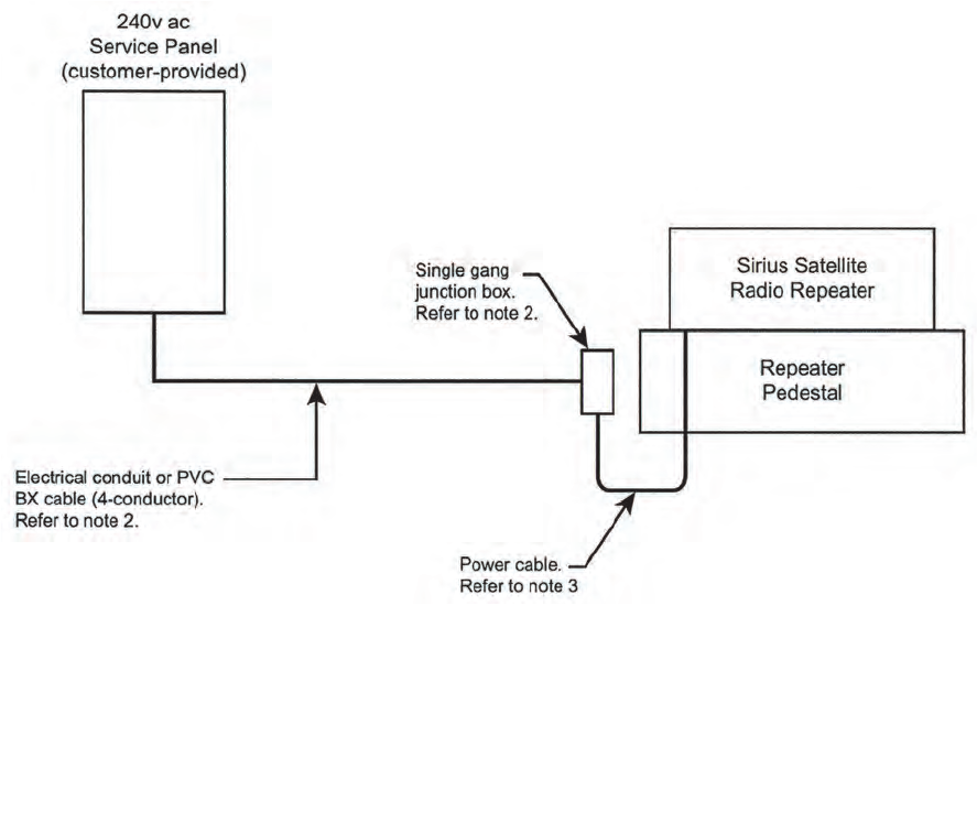
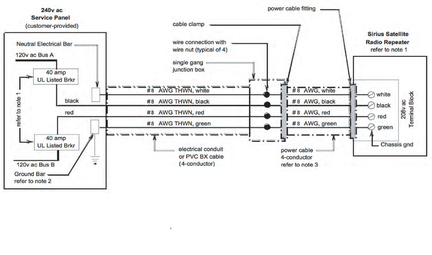
Figure 3 - 1 depicts the recommended site ac power wiring:
Figure 3 - 1 AC Wiring (Sheet 1 of 2)
Notes:
1. Refer to Sheet 2 for ac power wiring schematic.
2. Conduit or BX cable will be routed to a single gang junction box installed on the
repeater pedestal or in close proximity to the repeater enclosure.
3. 4-conductor #8 power cable will be installed between the junction box and the
repeater power terminal block. Refer to Sheet 2, note 3. DTR-1076
03/16/08
3
-
3
Figure 3 - 1 AC Wiring (Sheet 2 of 2)
DTR-1079
03/16/08
Notes:
1. The repeater must be powered directly from a 240v ac service panel with 40 amp UL listed circuit breakers.
2. The green ground wire is to be connected to a safety ground derived from a copper ground plane or rod.
3. A 4-conductor #8 power cable with rubber jacket rated at 90 C will be used.
4. The ac power wiring design and installation must conform to all local and national electrical codes.
3
-
4 This page intentionally left blank.
3EM21522AAAA Insta
ll
ation
Issue 1, March 2008 DTR-0200-SA-SIRIUS
3-5
3.5
REPEATER UNPACKING AND INSPECTION
The repeater equipment containers and the Fibergrate platform containers (or what-
ever platform is being utilized) should be unpacked and inspected at the earliest date
to ensure that all required material has been received and is in good condition.
Equipment should be checked against packing lists and site drawings.
3.5.1
Freight Damage
Any damage to material while in transit should be immediately directed to the
freight carrier. The carrier will issue instructions regarding freight damage claims.
3.5.2
Material Missing or Damaged
Questions pertaining to missing or damaged materials not due to the carrier should
be directed to Alcatel-Lucent at Longview, Texas, telephone number 1-903-236-5200.
Ask for Product Engineering.
3.6
SUGGESTED TOOL LIST
3.6.1
Installation Tools
No special tools are required to install DTR-0200-SA-SIRIUS (3EM04000AA)
Repeater equipment.
3.7
ANTENNA INSTALLATION
All antenna Installation, alignment, adjustment, and connecting procedures will be in
accordance with the antenna manufacturer’s instruction manual, A&E stamped Alca-
tel-Lucent construction/installation drawings, and tower owner specific requirements.
3.8
REPEATER CABINET INSTALLATION
3.8.1
Support Base
The support base to be used will depend on the individual site and the required
mounting position. Specific information is contained in the A&E Construction Draw-
ings for the particular site.
3.9
CABLE CONNECTIONS
(See
Figure 3 - 2
)
3.9.1
Module Connecting Cables and Module Connection Points
Refer to
Appendix B
for cable to-from descriptions and cable part numbers.

Insta
ll
ation 3EM21522AAAA
DTR-0200-SA-SIRIUS Issue 1, March 2008
3-6
3.9.2
External Cables and Connections
Prior to making any external connections, ensure that main
power to the repeater is turned off at the source and a
“
Warning, Do Not Turn On, Personnel Working
” sign is hang-
ing on the main source power switch.
3.9.2.1
External Connection Current Ratings
3.9.2.2
Chassis Ground Connection
The PDU chassis ground connecting wire will connect to the grounding terminal on
the repeater junction block.
3.9.2.3
Satellite Dish Receiving Antenna (VSAT) to Repeater
The feed cable from the VSAT antenna will connect to the Repeater Junction Box
VSAT IN connector. The actual cable type, length, connectors, etc., will be specified
on the construction drawings.
3.9.2.4
GPS Receiving Antenna to Repeater
The feed cable from the GPS antenna will connect to the Repeater Junction Box GPS
IN connector. The actual cable type, length, connectors, etc., will be specified on the
construction drawings.
3.9.2.5
Repeater to Tower Mounted Transmit Antenna
The feed cable to the transmit antenna will connect to the repeater RF output con-
nector on the underside of the repeater cabinet. The actual cable type, length, con-
nectors, etc., will be specified on the construction drawings.
EXTERNAL CONNECTION MAX CURRENT
External Heater Connection Max. Current 1.7A @ 120 VAC
Auxiliary Power Outlet Max. Current 5A @ 120 VAC

3EM21522AAAA Insta
ll
ation
Issue 1, March 2008 DTR-0200-SA-SIRIUS
3-7
3.9.2.6
Telephone Line (TELCO) Connections
To reduce the risk of fire, use only No. 26 AWG or larger (e.g.,
24 AWG) UL Listed or CSA Certified Telecommunication Line
Cord.
TELCO will determine the type and length of cable to be used. Connection will be to
the TELCO connector located on the rear panel of the SPU.
3.9.2.7
Electrical Service Connection
Refer to
Paragraph 3.4, SITE POWER
.
3-8 This page intentionally left blank.
3
-
9
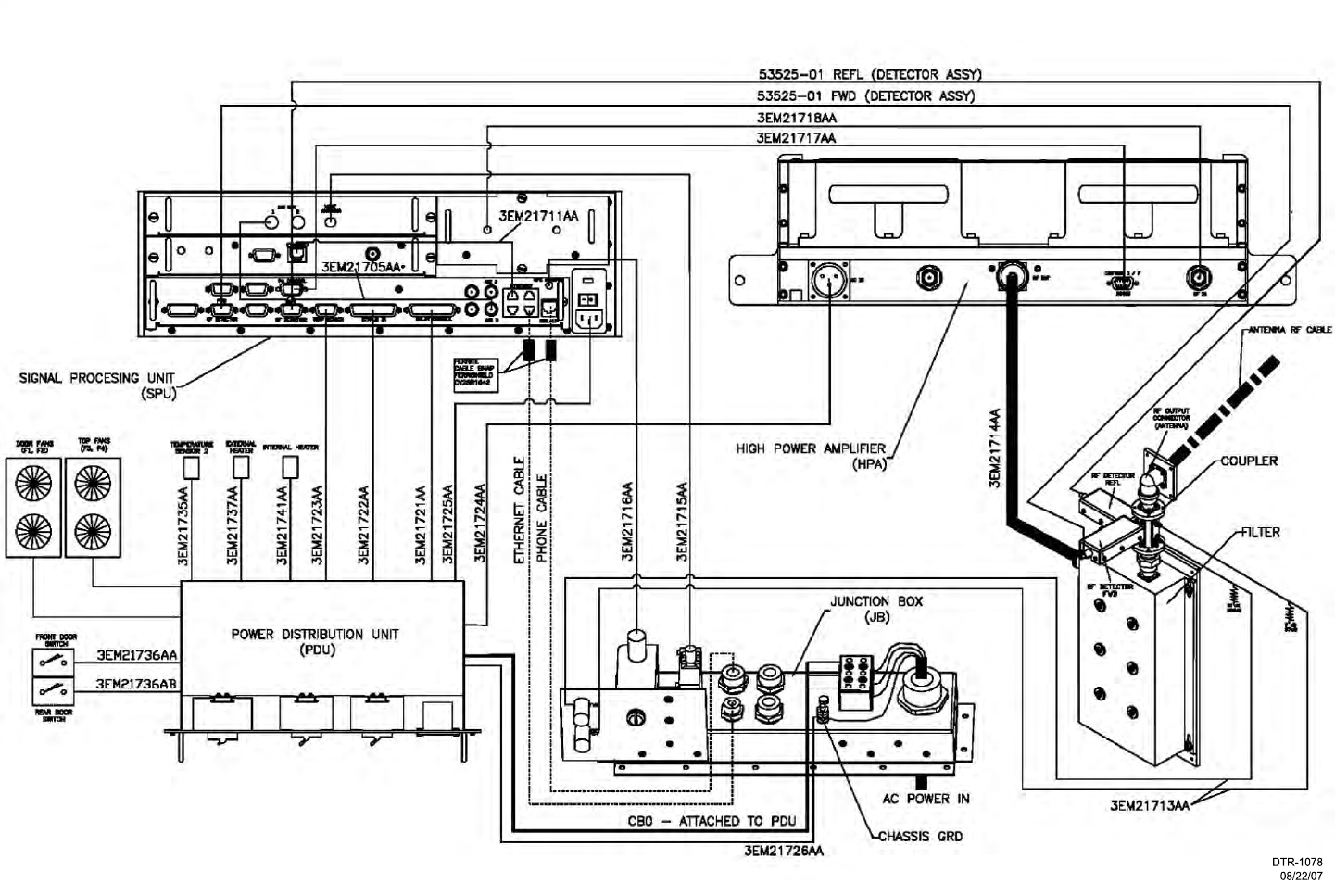
Figure 3 - 2 Repeater Interconnection Diagram
3
-
10 This page intentionally left blank.
3EM21522AAAA Insta
ll
ation
Issue 1, March 2008 DTR-0200-SA-SIRIUS
3-11
3.10
POST-INSTALLATION INSPECTION/TEST
Post installation inspecting/testing is described below as phase one, two, and three
inspecting and/or testing. Phase one and two inspecting/testing is to satisfy the site
owner that the system conforms to the owner’s requirements. Phase three testing is
the Alcatel-Lucent SIRIUS field test performed after installation or major equipment
maintenance to ensure that the repeater is performing according to SIRIUS require-
ments. An inspection/test form template is provided at the end of this section. A field
test report form template is provided at the end of the Turn-up and Testing section of
this manual.
3.10.1
Inspection/Test Phases
Post installation inspection/testing will normally consist of three phases involving
the site owner’s representative, Alcatel-Lucent’s representative, and SIRIUS
Radio’s representative. A written record of each phase will be made identifying the
specific inspections and/or test(s) accomplished and the satisfactory or unsatisfac-
tory result(s) of each. A copy of the results will be furnished to each participating
representative.
3.10.1.1
Phase One Inspection/Testing
Phase one inspection/testing will be performed at the discretion of the site owner’s
representative. The purpose is to ensure that Alcatel-Lucent installed equipment
meets all requirements established by the site owner. The site owner’s representa-
tive
(s) in conjunction with the Alcatel-Lucent representative and the SIRIUS Radio
representative will be involved in the inspection/testing process. Deficiencies will be
identified, recorded, and presented to the Alcatel-Lucent representative for correction.
3.10.1.2
Phase Two Inspection/Testing
Phase two will only be required if there were discrepancies found during the phase
one inspection/testing. After correction of the discrepancies, the site owner’s repre-
sentative, Alcatel-Lucent’s representative, and SIRIUS Radio’s representative will
once again be involved in an inspection/test to ensure satisfactory correction. Results
of the phase two inspection/testing will be recorded and signed by all representatives
and a copy distributed to each.
3.10.1.3
Phase Three Testing
Phase three testing consists of The Alcatel-Lucent representative in conjunction with
a SIRIUS Radio representative performing repeater system field testing to ensure
satisfactory system operation. Final test results will be recorded and signed by each
representative who in turn will receive a signed copy.
3.10.2
Repeater System Field Testing
Refer to
Section 4, Turn-Up and Testing
in this manual for the system field test proce-
dure and
Paragraph 3.11, Post Installation Inspection/Test Form
template.
3-12 This page intentionally left blank.
3EM21522AAAA Insta
ll
ation
Issue 1, March 2008 DTR-0200-SA-SIRIUS
3-13
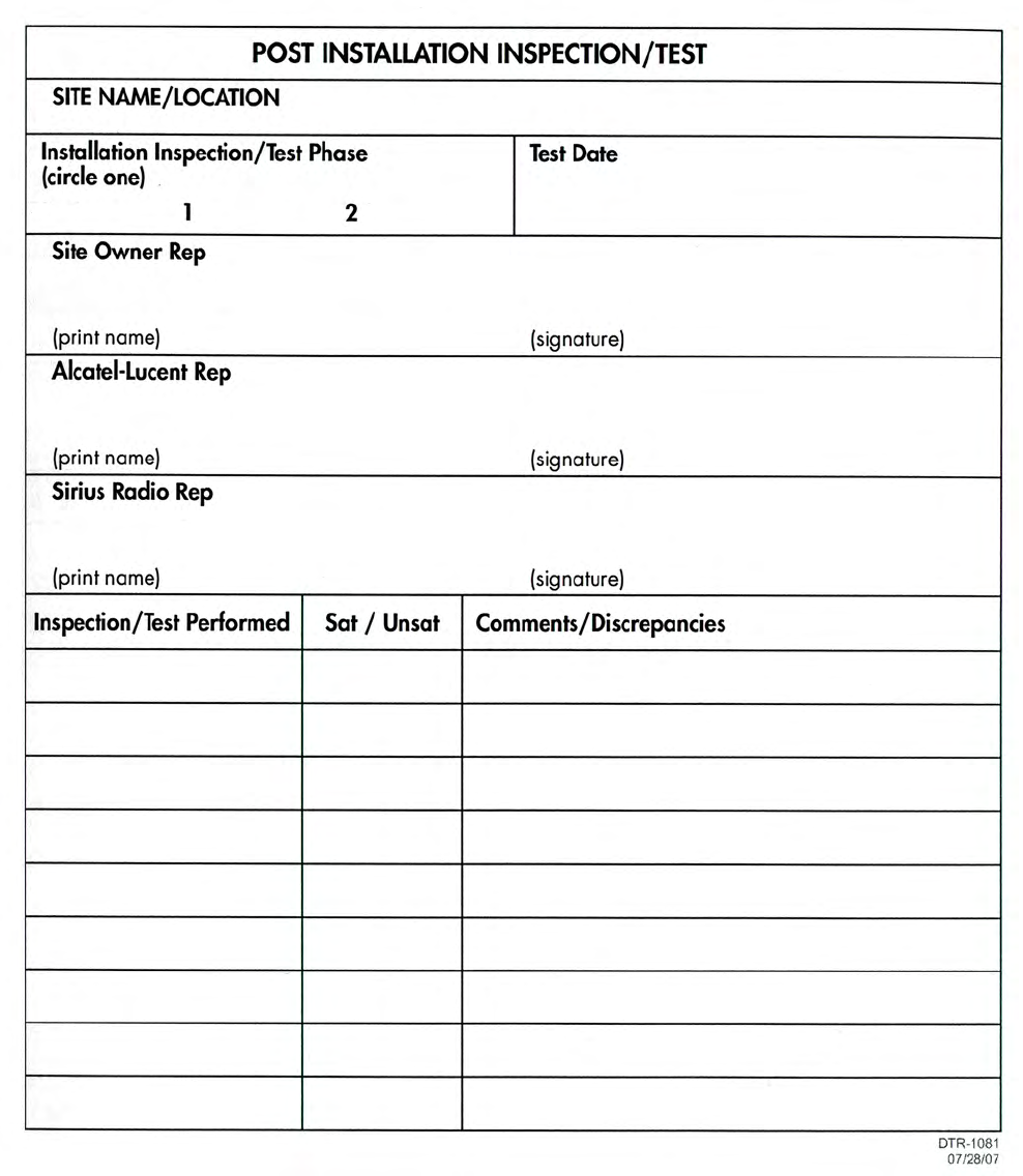
3.11
POST INSTALLATION INSPECTION/TEST FORM
3-14 This page intentionally left blank.

3EM21522AAAA Turn-Up an
d
Testing
Issue 1, March 2008 DTR-0200-SA-SIRIUS
4-1
4TURN-UP AND TESTING
4.1
GENERAL
This section describes the procedures required to turn-up and test the DTR-0200-SA-
SIRIUS repeater (ALU Part Number 3EM04000AA) after replacement of the Signal
Processor Unit (SPU), software upgrading, and/or other maintenance. These proce-
dures consist of repeater provisioning and field testing.
These procedures require GUI software screen access. For screen access pro-
cedures, refer to the Operations section of this manual.
4.2
TEST EQUIPMENT REQUIRED
Refer to Table 4-1 for required test equipment. Become familiar with the operation of
any test equipment before using it. Operating instructions for test equipment are not
included in this manual except for precautionary notes or special instrument settings
required for performance of a test procedure. When further information regarding test
equipment is required, refer to the equipment manufacturer’s instructional data.
Table 4-1 Test Equipment Required
Type
Power Meter
Power Meter Test Sensor
PC/Laptop
Turn-Up an
d
Testing 3EM21522AAAA
DTR-0200-SA-SIRIUS Issue 1, March 2008
4-2
4.3
REPEATER PROVISIONING
Provisioning is the process of checking, changing, and/or installing parameter values
to allow the repeater to operate from its assigned location. Normally, no parameter
changes will be required except after replacement of the SPU.
1
Turn on repeater power
2
Connect computer to repeater controller Ethernet port
3
Access repeater GUI
4
Set repeater to Standby mode
5
Provision Repeater (check, change, install parameters as indicated by GUI
screen readings and consistent with local network engineering require-
ments)
6
Return repeater to Broadcast mode
7
Connect repeater to NMC.
4.4
FIELD TESTS
The purpose of the field test is to verify that the repeater meets specifications after
on-site repair. The field test will be performed with the Ku-Band Receive Chain of the
specific site.
A field test report form is provided to record the operating conditions and critical per-
formance parameters of the repeater after repair. This report should be kept on file
and referred to whenever the repeater is retested (after maintenance, etc.).
4.4.1
Test Set-Up
1
Remove power from repeater by opening repeater main power circuit
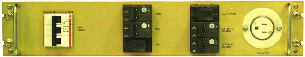
breaker on the PDU (see Figure 4 - 1).
Figure 4 - 1 PDU Circuit Breaker Panel
3EM21522AAAA Turn-Up an
d
Testing
Issue 1, March 2008 DTR-0200-SA-SIRIUS
4-3
2
Set up the test system as shown in Figure 4 - 2.
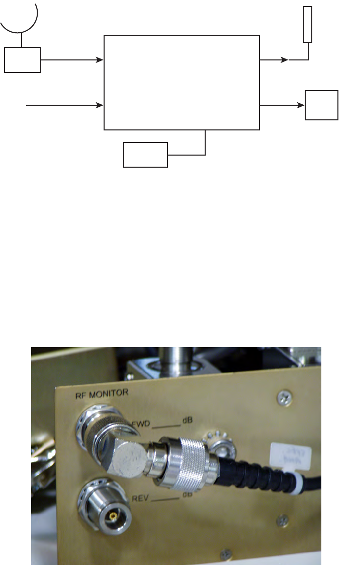
Figure 4 - 2 Field Test Setup For Terrestrial Repeater
• Connect the power meter to the FWD RF MONITOR connector on the
junction box panel.
• Enter into the power meter the dB offset value listed at the FWD RF
MONITOR connector. See Figure 4 - 3.
Figure 4 - 3 RF Monitor Connectors on Junction Box Panel
Sirius Repeater
LNB
Ethernet
Test PC
Fw MON
RF OutVSAT In
DTR-1070
03/16/08
DVB/S Signal
Ku Band
Antenna
208V AC
Power
Meter
Antenna
The input power value can be anywhere from 188 to 250
VAC depending on the available site power.
Turn-Up an
d
Testing 3EM21522AAAA
DTR-0200-SA-SIRIUS Issue 1, March 2008
4-4
• The Ethernet connection for the PC is on the back panel of the Main
Controller (one of the Ethernet ports in the four port block). See
Figure 4 - 4.
Figure 4 - 4 Ethernet Ports on Main Controller Back Panel
• The input power value can be anywhere from 188 to 250 VAC depend-
ing on the available site power.
4.4.2
Operating Mode
1
Power up the repeater.
2
Wait 5 minutes (after the Main Controller finishes initialization).
3
Start GUI.
4
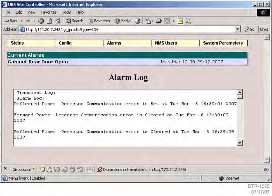
Access the Repeater Operating Mode screen and set repeater to Standby
Mode (see Figure 4 - 5).
Figure 4 - 5 Repeater Operating Mode
3EM21522AAAA Turn-Up an
d
Testing
Issue 1, March 2008 DTR-0200-SA-SIRIUS
4-5
4.4.3
Alarm Checking
1
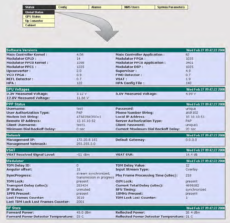
Access to Alarm Log and read system faults/alarms from controller (see
Figure 4 - 6).
2
No fault/alarm shall be reported other than Cabinet Rear Door Open. This
alarm will appear because of the PC connection to the rear panel of the
Main Controller.
Figure 4 - 6 GUI Alarm Log
Turn-Up an
d
Testing 3EM21522AAAA
DTR-0200-SA-SIRIUS Issue 1, March 2008
4-6
4.4.4
Software/Firmware Configuration Test
1
Access the Global Status screen.
2
Check and record software/firmware versions used in the repeater.
Figure 4 - 7 Global Status Screen
3
The version numbers shall match those defined by the repeater
configuration.

3EM21522AAAA Turn-Up an
d
Testing
Issue 1, March 2008 DTR-0200-SA-SIRIUS
4-7
4.4.5
VSAT Receiver Test
1
View the Global Status screen.
2
Confirm that the receive antenna is correctly pointed at the satellite (deter-
mined by VSAT Receiver Signal Strength reading on GUI screen).
3
Ensure that the receive antennas are correctly pointed at the satellite
(determined by signal strength reading on GUI screen).
4
If necessary, reconfigure the repeater VSAT receiver to match the satellite
signal.
Default settings are in place for the repeater for DVBS Standard (DVBS1),
Polarization (Horizontal), Band (Low) and Symbol Rate (8417361). In the
factory VSAT Frequency is set to 1222.000 MHz. All of the settings are based
on the SIRIUS satellite broadcast signal and are made in the factory. The
only settings that could need to be changed in the field based on a change in
the SIRIUS satellite broadcast signal would be Frequency and Symbol Rate.
5
Verify that the TDM lock is present, and that the VSAT SNR is better than
10 dB.
4.4.6
GPS Receiver Test
Verify from the GUI Global Status screen that 1 PPS and 10 MHz signals are present.
4.4.7
Output Power Test
1
Access the Repeater Operating Mode screen (see Figure 4 - 5).
2
Set the Repeater Operating Mode to Broadcast.
3
Access the Modulator Mode screen (Figure 4 - 8).
4
Set the Modulator Operating Mode to CW.

Turn-Up an
d
Testing 3EM21522AAAA
DTR-0200-SA-SIRIUS Issue 1, March 2008
4-8
Figure 4 - 8 Modulator Mode Screen
5
Set RF output power to +53.0 dBm, and measure the RF output power at
the junction box forward coupled jack, CPL FWR, with power meter. The
measured RF power level shall be within ±0.5 dB from the set RF power
level indicated on the GUI Global Status screen.
6
Remove the power meter from the FWD RF MONITOR connector.
No alarm shall be reported other than door(s) open.
4.5
CONNECT REPEATER SYSTEM TO NMC
Coordinate with NMC and place repeater in remote operating condition.

3EM21522AAAA Turn-Up an
d
Testing
Issue 1, March 2008 DTR-0200-SA-SIRIUS
4-9
4.6
FIELD TEST REPORT
DTR-1073
05/16/08
SITE:
Test Requirement Result
DATE OF TEST:
TEST TECHNICIAN
Printed Name:
COMPANY:
Printed Name:
Alarm Check
Firmware Configuration
VSAT Receiver
GPS Receiver
Output Power
No fault/alarm
Match versions in SPU, Controller,
and HPA
S/N ratio>10dB
1 ppm and 10MHz present
Within ±0.5 dB of set power level
COMPANY:
FIELD TEST REPORT
4-10 This page intentionally left blank.
3EM21522AAAA OPERATION
Issue 1, March 2008 DTR-0200-SA-SIRIUS
5-1
5OPERATION
5.1
GENERAL
This section addresses control, communication, and parameter modifications of the
DTR-0200-SA-SIRIUS terrestrial repeater. It also provides descriptions of controls,
indicators, test points, and connectors for the repeater.
Refer to Paragraph 5.7 for repeater operating procedures.
Refer to Paragraph 5.8 for controls and indicators.
5.2
CONTROL AND COMMUNICATION
The DTR-0200-SA-SIRIUS terrestrial repeater can operate in either of two condi-
tions; remote control condition or local control condition
5.2.1
Remote Control Condition
In the remote control condition the Network Management Center (NMC) operator can
control and monitor the repeater from his/her position via telephone line dial-up, and
by use of WEB and SNMP interfaces to perform network management.
5.2.2
Local Control Condition
In the local control condition the technician can control and monitor the repeater from
the terrestrial site location. The technician uses a laptop PC for local control and
maintenance procedures. The PC communicates with the repeater via Ethernet and
Graphical User Interface (using Internet Explorer) or Command Line Interface (CLI)
protocol using the RS-232 Comm Port.
5.2.3
Control and Communication Interfaces
There are three interface ports provided for control and communication. They are:
• RS-232 Serial Port (DB9) –used for local control, status information, initial setup,
and troubleshooting. Access is local via laptop PC and the supported protocol is
Command Line Interface (CLI).
• V90 Modem Port (RJ11) – used for remote control and status information. Access
is from the NMC via dial-up modem and telephone and the supported protocols
are SNMP
, WEB Interface, and Telnet.
• Ethernet Port (RJ45) – used for local control and LAN access. Access is local and
the supported protocols are SNMP, WEB Interface, and Telnet.
5.2.4
Remote/Local Control Switching
The normal condition for repeater operation is the remote control condition. For a tech-
nician to perform testing and maintenance from the local terrestrial site, the repeater
must be switched to the local control condition. Switching is activated by the use of an
SPU front panel push-button switch. LEDs on either side of the switch identify the
repeater control condition as being in local or remote. Placing the repeater in the local
OPERATION 3EM21522AAAA
DTR-0200-SA-SIRIUS Issue 1, March 2008
5-2
mode prevents a remote operator from accidentally turning on the HPA from the
remote site and applying high RF level from the repeater. This could seriously injure
the technician working on the repeater at the local site and/or damage the repeater.
5.3
MODES OF OPERATION
There are two main parameter groups which determine the operating mode. They are
the Repeater Operating Mode parameter group and the Modulator Operating Mode
parameter group.
5.3.1
Repeater Operating Modes
The three repeater operating modes are Broadcast, Standby, and Manual. The
repeater’s normal operating mode is Broadcast. Under normal, no-fault, conditions if
the repeater has an AC power shut-down, upon return of power its AC power-up algo-
rithm will restore operation to the same mode of operation prior to the loss of power.
5.3.1.1
Broadcast Mode
This mode allows the repeater to transmit real signals or test signals, run all the pro-
tection loops and ALC. This is the normal operating mode for the repeater. It receives
its input signal from the satellite, or generates a test signal, and transmits an orthog-
onal frequency division multiplexing (OFDM) signal for terrestrial broadcast. In this
mode, the Main Controller automatically maintains all repeater functions. To operate
in the Broadcast mode, the following conditions must be met:
• The repeater must be receiving an input signal and be locked to the input
stream (if the modulator is in the test mode, the VSAT satellite signal
presence is ignored).
• The ALC loop must be running.
• There must be good GPS signal quality (if the modulator is in the test
mode, the GPS signal presence is ignored).
• There must be no modulator alarms.
• There must be no VSAT alarms (if the modulator is in the test mode, the
VSAT satellite signal presence is ignored).
• There must be no GPS alarms (if the modulator is in the test mode, the
GPS signal presence is ignored).
• There must be no Up-converter alarms.
• There must be no Reflected Power alarms.
5.3.1.2
Standby Mode
In this mode the repeater is off the air and affirms that the HPA is off while all other
components are operating normally. The up-converter output is muted, ALC is off, and
the HPA is switched off by disabling the HPA power supply.

3EM21522AAAA OPERATION
Issue 1, March 2008 DTR-0200-SA-SIRIUS
5-3
The operating conditions in the Standby mode are:
• AC power is applied to the SPU, HPA, and fans.
• The HPA power supply is disabled.
• The HPA RF switch is OFF.
• The Up-converter output is muted.
• The cabinet fans are turned on.
5.3.1.3
Manual Mode
This mode allows manual control of the repeater for the technician to perform mainte-
nance and/or testing or troubleshooting. In the Manual Mode most commands can
only be accessed through the “administrator” login. The operator must log in as a sys-
tem administrator using the default password “ipradmin”. The operator now has
authority to alter parameters.
The manual mode must be used with caution. If parameters
are changed indiscriminately, unintentional damage to the
repeater and loss of factory settings could occur.
When the repeater is switched to the Manual Mode, it maintains all its system set-
tings which were in effect prior to the switchover. The RF output DAC last value will
remain until changed by the operator. The range of DAC values is limited to those
within the minimum and maximum permitted values required to maintain the up-
converter output power.
5.3.2
Modulator Operating Modes
• The modulator has seven operating modes:
• Standby Mode
• Run Mode
• CW Mode
• Two Tones Mode
• Notch Mode
• Comb Mode
• PRBS Mode
Of these seven operating modes, the technician will only use Standby Mode and Run
Mode. All other modes are for factory use only.
WARNING
Possibility of
Damage
to Equipment
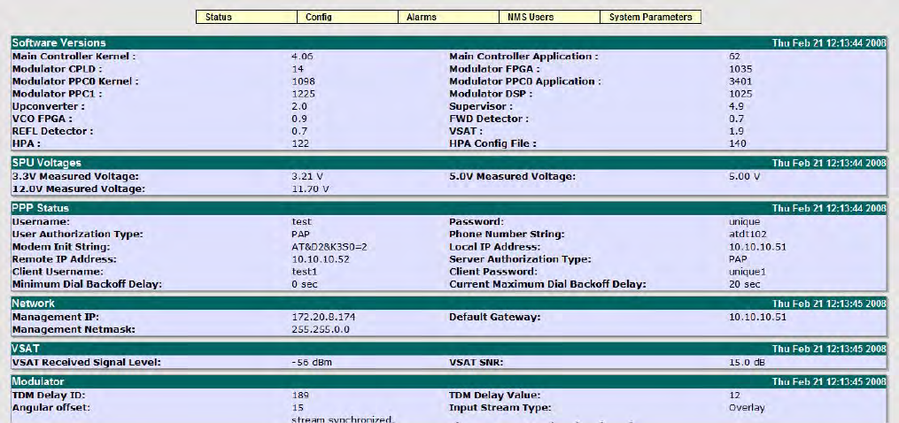
OPERATION 3EM21522AAAA
DTR-0200-SA-SIRIUS Issue 1, March 2008
5-4
5.4
GRAPHICAL USER INTERFACE (GUI)
The GUI WEB interface uses a PC for maintenance and support of the repeater,
and for fault and status reporting. The interface uses a simple hierarchical menu
structure which is user friendly and provides access to parameters. The parameters
are classified in five categories; Status, Configuration, Alarms, NMS User, and System
Parameter. Figure 5 - 1 shows the GUI Main Menu which, in addition to providing cur-
rent repeater operating information, provides access to set up or change parameters as
required. The parameter categories and their pull down submenus are accessed from
the
GUI Main Menu. These submenu screens are self-explanatory and subdivide the
repeater’s status and parameters according to their functionalities. See
Figure 5 - 2
.
Figure 5 - 1 GUI Main Menu

3EM21522AAAA OPERATION
Issue 1, March 2008 DTR-0200-SA-SIRIUS
5-5
Figure 5 - 2 GUI Pull-Down Menus
5.5
GUI MENU DESCRIPTIONS
5.5.1
Status Sub-Menu Breakdown
Status shows the repeater current operating status.
To access the Status sub-menu; GUI Main Menu => Status
The Status sub-menus are divided as follows:
Global Status
GPS Status
Up Converter
Cabinet
Status
Global Status
GPS Status
Up-Converter
Cabinet
Modulator
VSAT
Repeater Output Level
Coupler
GPS
Temperature
Repeater Operating Mode
PPP Dial In Parameters
PPP Dial Out Parameters
PPP Misc Parameters
Site
Alarms
Identification
Access Control
Network Parameters
SNMP Parameters
Heartbeat Time
System Reset
Upgrade
User Properties
Alarm Properties
Clear Logs
Alarm Status
Config NMS Users System Parameters
DTR-1016
06/11/07
GUI CONTROLLER MAIN MENU
Repeater ID
Modulator Mode
Overlay
Delays
Modulator IP
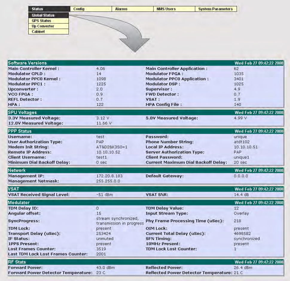
OPERATION 3EM21522AAAA
DTR-0200-SA-SIRIUS Issue 1, March 2008
5-6
Their individual GUI screens follow.
Figure 5 - 3 Global Status Screen
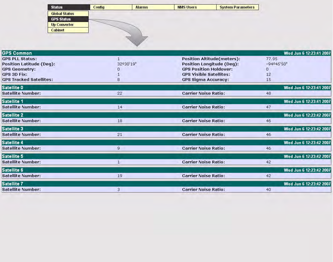
3EM21522AAAA OPERATION
Issue 1, March 2008 DTR-0200-SA-SIRIUS
5-7
Figure 5 - 4 GPS Status Screen
OPERATION 3EM21522AAAA
DTR-0200-SA-SIRIUS Issue 1, March 2008
5-8
Figure 5 - 5 Up-Converter Status Screen
Figure 5 - 6 Cabinet Status Screen
5.5.2
Configuration (Config) Sub-Menu Breakdown
Configuration screens allow modification of the parameters according to operator
requirements. To access the Configuration sub-menu; GUI Main Menu =>Config
The Configuration sub-menus are divided as follows:
Modulator
VSAT
Repeater Output Level
Coupler
GPS
Temperature
Repeater Operating Mode
PPP Dial In Parameters
PPP Dial Out Parameters
PPP Misc Parameters
Site
3EM21522AAAA OPERATION
Issue 1, March 2008 DTR-0200-SA-SIRIUS
5-9
Figure 5 - 7 GUI Main Menu Config Drop-Down Menu
Config Modulator breaks down into a further sub-menu as follows:
Repeater ID
Modulator Mode
Overlay
Delays
Modulator IP
To access the Modulator sub-menu; GUI Main Menu=>Config=>Modulator=> (sub-
menu selection). See Figure 5 - 8.
Figure 5 - 8 Config Modulator Sub-Menu
OPERATION 3EM21522AAAA
DTR-0200-SA-SIRIUS Issue 1, March 2008
5-10
Figure 5 - 9 through Figure 5 - 13 show the individual screens accessed via the Config
Modulator sub- menu.
Figure 5 - 9 Repeater ID Screen
The Modulator Mode screen, Figure 5 - 10, allows changeover from Repeater Operat-
ing Mode to Modulator Operating Mode (refer to para Paragraph 5.3.2). Mode selec-
tion is from the Modulator Mode drop-down screen and allows access to the following
modes (only Standby and Run are used in the field, the remaining five are for factory
use only):
Standby
Run
CW
Two Tones
Notch
Comb
PRBS Spectrum
3EM21522AAAA OPERATION
Issue 1, March 2008 DTR-0200-SA-SIRIUS
5-11
I
Figure 5 - 10 Modulator Mode Screen
OPERATION 3EM21522AAAA
DTR-0200-SA-SIRIUS Issue 1, March 2008
5-12
Figure 5 - 11 Overlay Screen
3EM21522AAAA OPERATION
Issue 1, March 2008 DTR-0200-SA-SIRIUS
5-13
Figure 5 - 12 Delays Screen
Figure 5 - 13 Modulator IP Screen
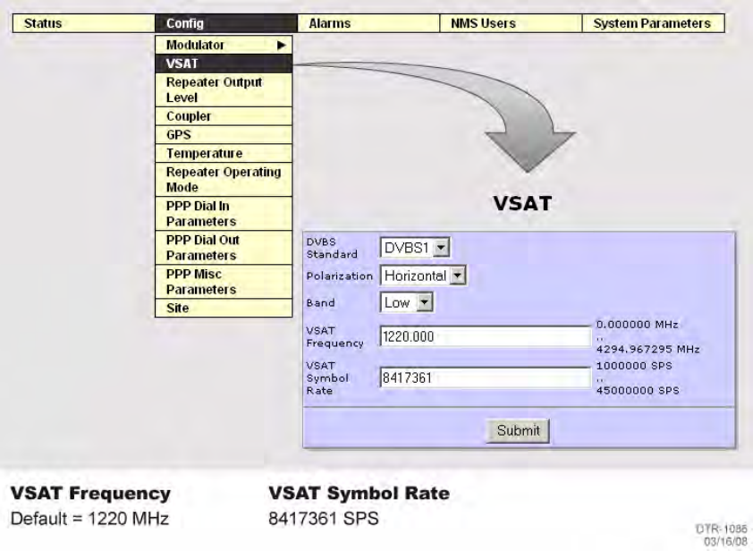
OPERATION 3EM21522AAAA
DTR-0200-SA-SIRIUS Issue 1, March 2008
5-14
The remainder of the Config menu displays the following screens:
VSAT
Repeater Output Level
Coupler
GPS
Temperature
Repeater Operating Mode
PPP Dial In Parameters
PPP Dial Out Parameters
PPP Misc Parameters
Site
Figure 5 - 14 through Figure 5 - 23 show the individual aforementioned screens
accessed via the Config menu.
Figure 5 - 14 VSAT Screen
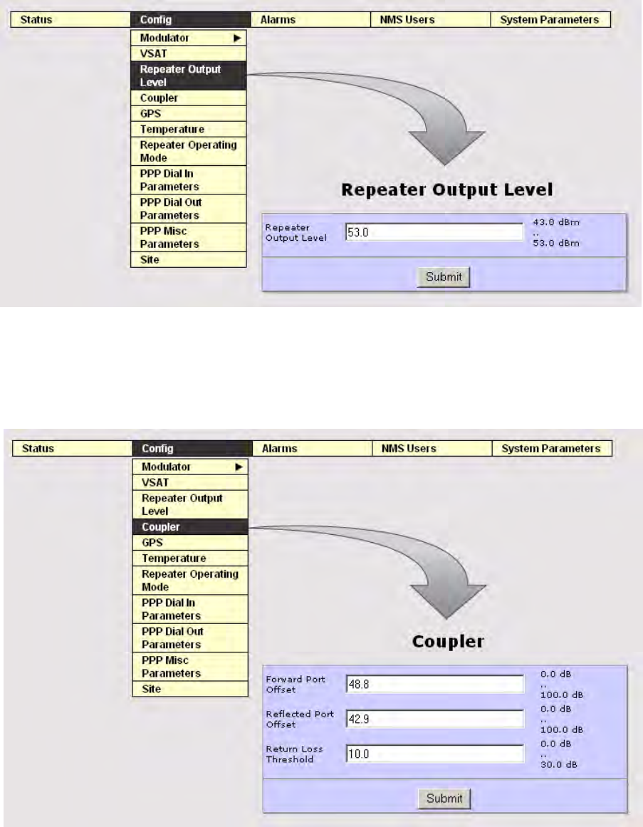
3EM21522AAAA OPERATION
Issue 1, March 2008 DTR-0200-SA-SIRIUS
5-15
Figure 5 - 15 Repeater Output Level Screen
Figure 5 - 16 Coupler Screen
OPERATION 3EM21522AAAA
DTR-0200-SA-SIRIUS Issue 1, March 2008
5-16
Figure 5 - 17 GPS Screen
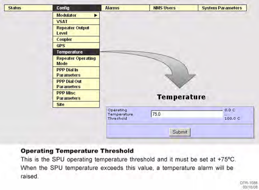
3EM21522AAAA OPERATION
Issue 1, March 2008 DTR-0200-SA-SIRIUS
5-17
Figure 5 - 18 Temperature Screen
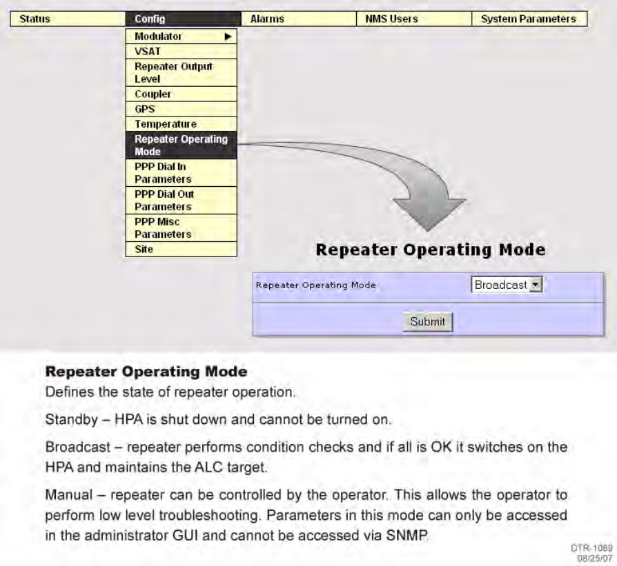
OPERATION 3EM21522AAAA
DTR-0200-SA-SIRIUS Issue 1, March 2008
5-18
Figure 5 - 19 Repeater Operating Mode Screen
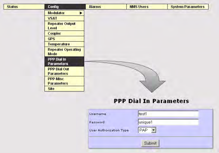
3EM21522AAAA OPERATION
Issue 1, March 2008 DTR-0200-SA-SIRIUS
5-19
Figure 5 - 20 PPP Dial In Parameters Screen
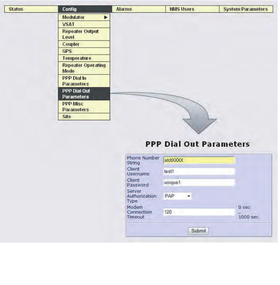
OPERATION 3EM21522AAAA
DTR-0200-SA-SIRIUS Issue 1, March 2008
5-20
Figure 5 - 21 PPP Dial Out Parameters Screen
DTR-1098
03/06/08
Phone Number String – Always begin with ATDT then add phone number of NMC. If required, precede
number with external line prefix.
Modem Connection Timeout – For dial out reliability do not use less then 120.
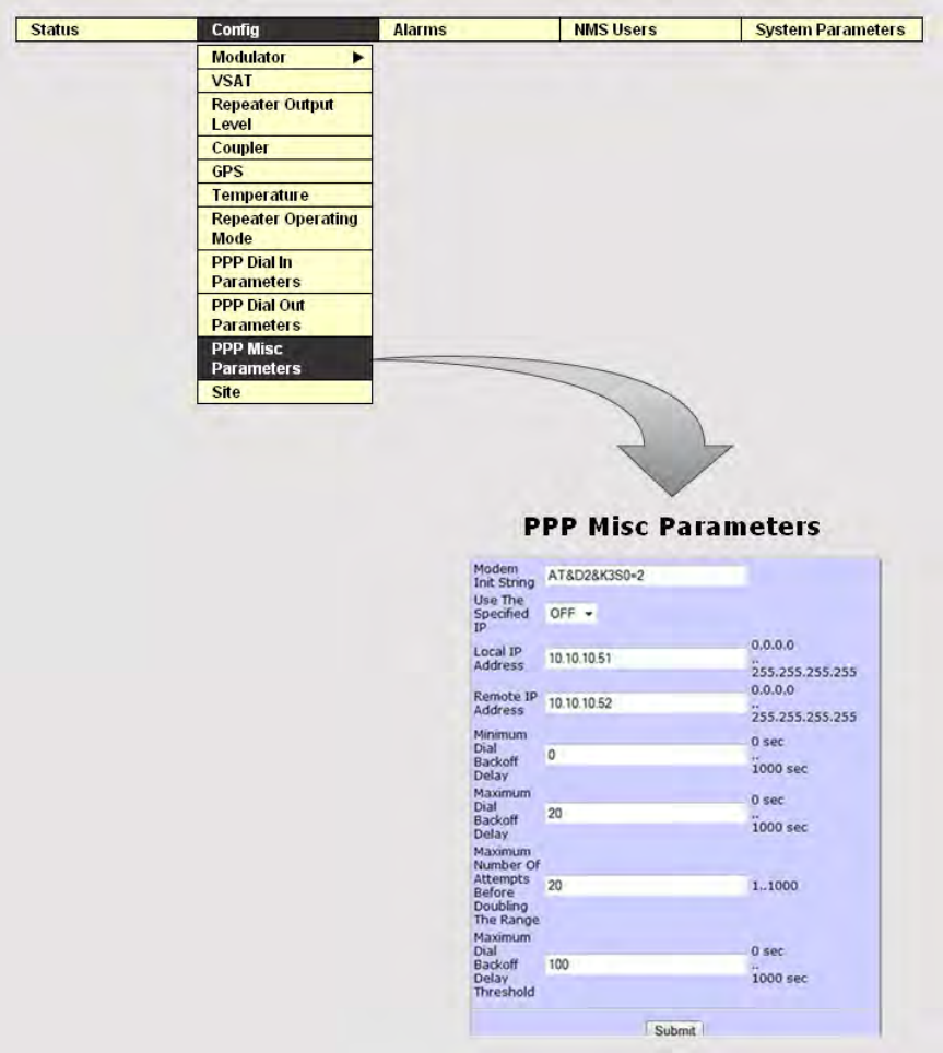
3EM21522AAAA OPERATION
Issue 1, March 2008 DTR-0200-SA-SIRIUS
5-21
Figure 5 - 22 PPP Misc Parameters Screen
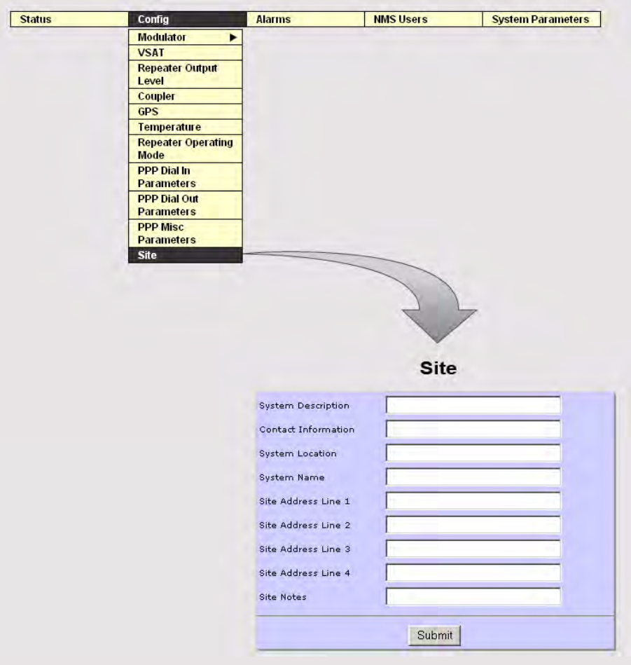
OPERATION 3EM21522AAAA
DTR-0200-SA-SIRIUS Issue 1, March 2008
5-22
Figure 5 - 23 Site Screen
5.5.3
Alarms Sub-Menu Breakdown
Alarms shows the repeater current alarm status, alarm log, and allows the user to
configure alarms according to user requirements.
To access the Alarms sub-menu; GUI Main Menu => Alarms
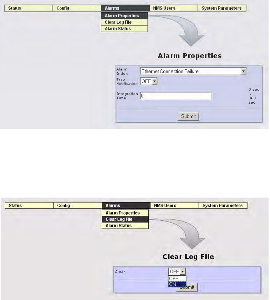
3EM21522AAAA OPERATION
Issue 1, March 2008 DTR-0200-SA-SIRIUS
5-23
The Alarm sub-menus are divided as follows:
Alarm Properties
Clear Log File
Alarm Status
The individual GUI screens follow.
Figure 5 - 24 Alarm Properties Screen
Figure 5 - 25 Clear Log File Screen
DTR-1100
03/06/08
Integration Time = Time in seconds that the repeater software will sample the condition
causing the alarm - to make sure the cause is present during the whole period of time. This is
used when the alarm changes from Cleared to Set. Value 0 means that the first time the condi-
tion is detected, the alarm will be set.
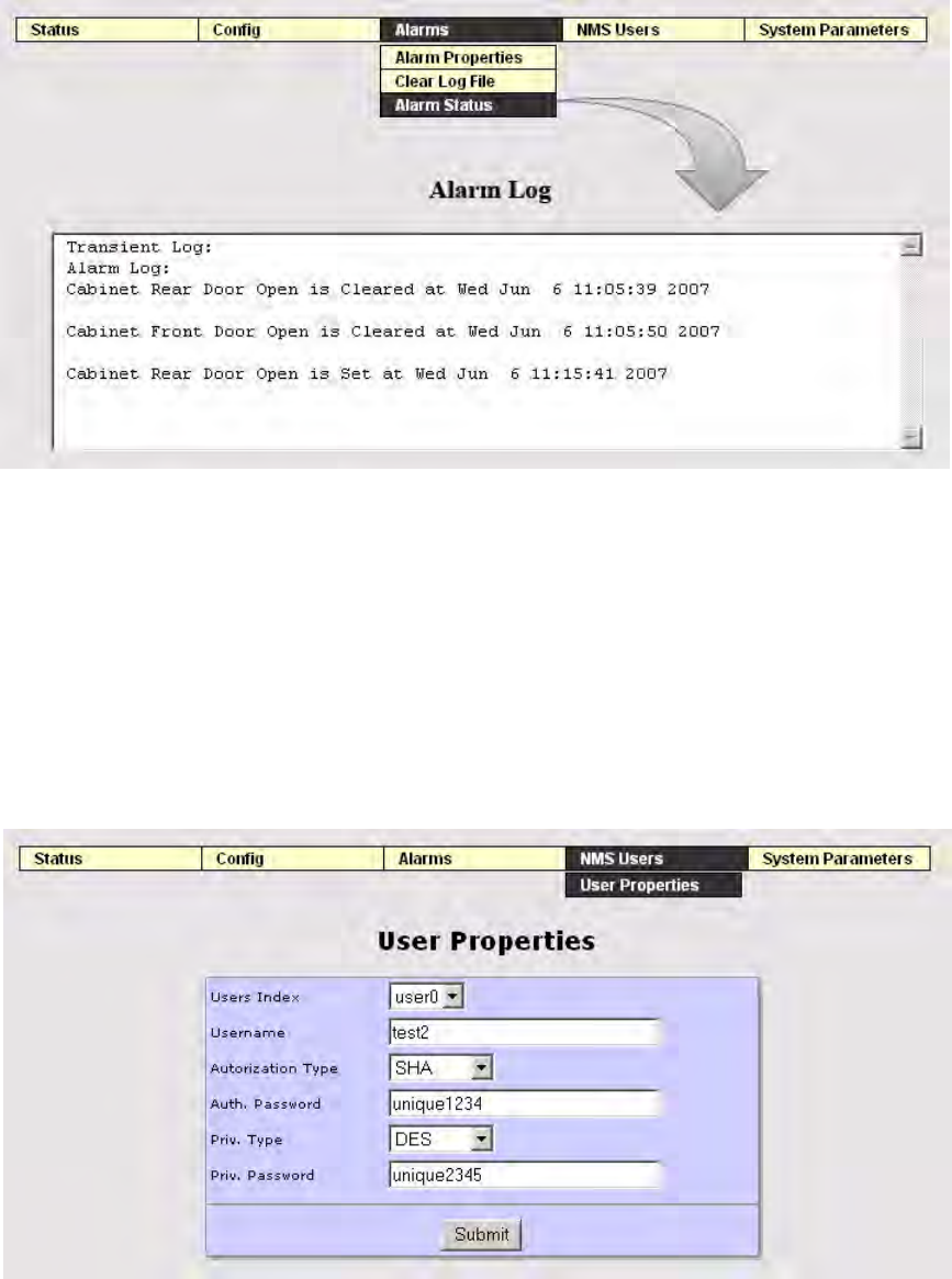
OPERATION 3EM21522AAAA
DTR-0200-SA-SIRIUS Issue 1, March 2008
5-24
Figure 5 - 26 Alarm Status Screen
5.5.4
NMS Users Sub-Menu Breakdown
The NMS Users screen shows identification and authorization parameters. To access
the NMS Users sub-menu; GUI Main Menu => NMS Users => User Properties. See
Figure 5 - 27.
Figure 5 - 27 Access to User Properties Screen
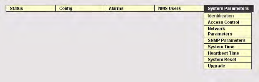
3EM21522AAAA OPERATION
Issue 1, March 2008 DTR-0200-SA-SIRIUS
5-25
5.5.5
System Parameters Menu
To access the System Parameters sub-menu: GUI Main Menu=>System Parameters.
See Figure 5 - 28.
Figure 5 - 28 Access to System Parameters Sub-Menu
The System Parameters sub-menu is divided as follows:
Identification
Access Control
Network Parameters
SNMP Parameters
System Time
Heartbeat Time
System Reset
Upgrade
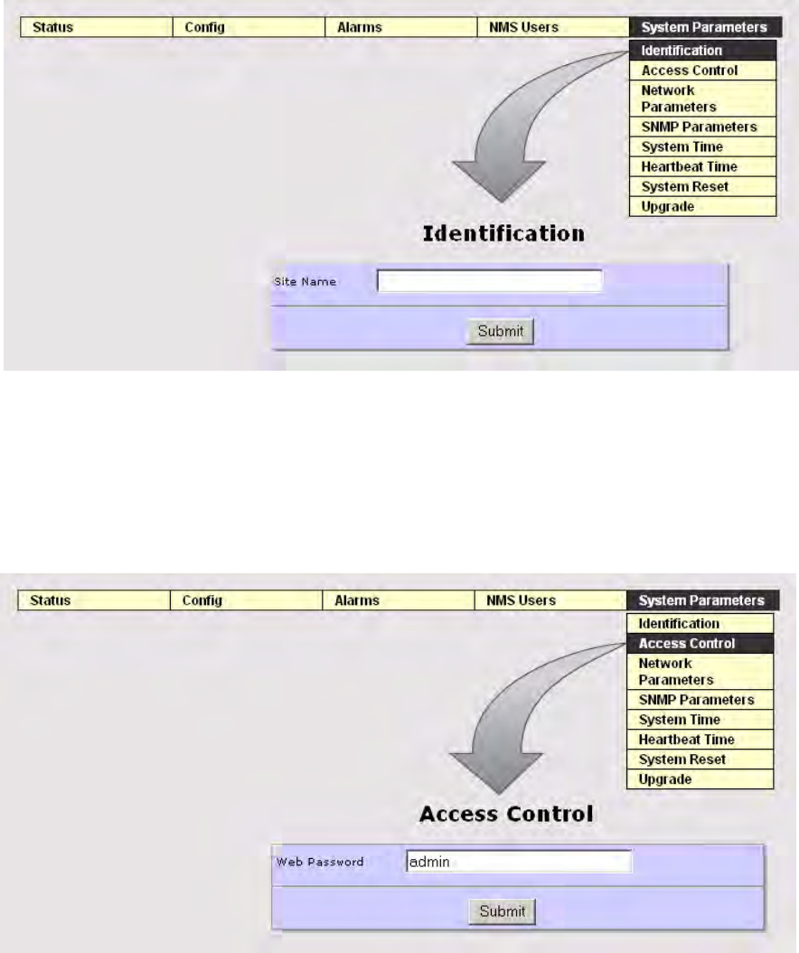
OPERATION 3EM21522AAAA
DTR-0200-SA-SIRIUS Issue 1, March 2008
5-26
The individual GUI screens follow:
Figure 5 - 29 System Parameters Identification Screen
Figure 5 - 30 System Parameters Access Control Screen
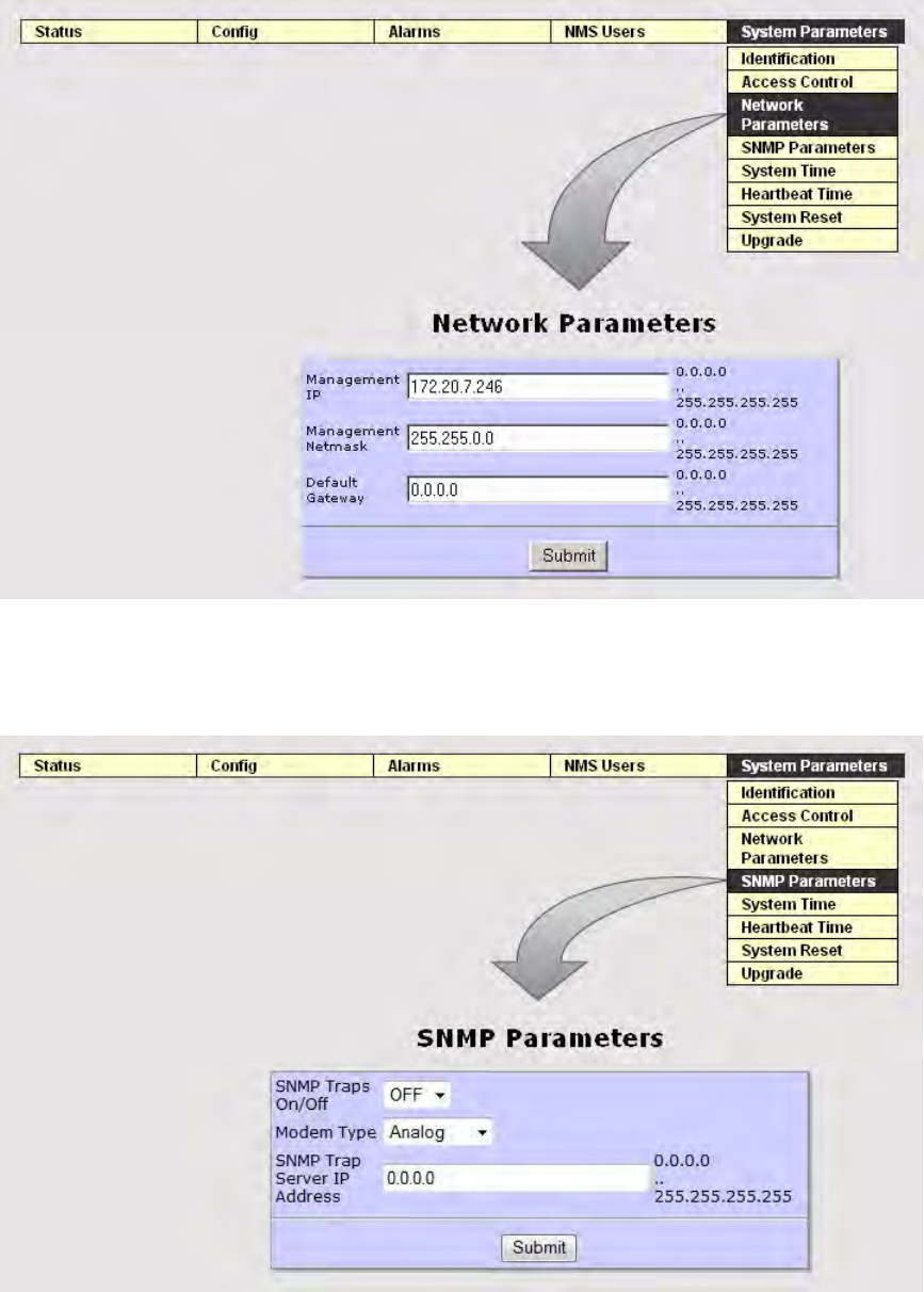
3EM21522AAAA OPERATION
Issue 1, March 2008 DTR-0200-SA-SIRIUS
5-27
Figure 5 - 31 System Parameters Network Parameters Screen
Figure 5 - 32 System parameters SNMP Parameters Screen
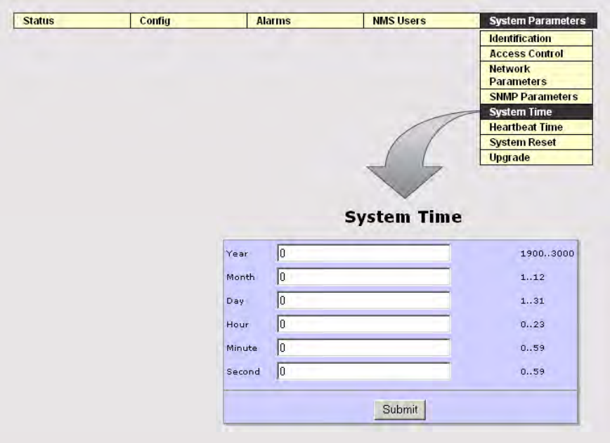
OPERATION 3EM21522AAAA
DTR-0200-SA-SIRIUS Issue 1, March 2008
5-28
Figure 5 - 33 System Parameters System Time Screen
3EM21522AAAA OPERATION
Issue 1, March 2008 DTR-0200-SA-SIRIUS
5-29
Figure 5 - 34 System Heartbeat Time Screen
DTR-1090
03/05/08
The Heartbeat screen allows the user to set the Heartbeat transmission inter-
val to the NMC
Heartbeat Hour Start*
Reference hour from the current day
Heartbeat Minute Start*
Reference minute
Heartbeat Pace
Interval in minutes that the heartbeat traps are generated.
Warning
A Heartbeat pace of less than 10 minutes could prevent remote dial-in and
possibly require local access in order to perform any reconfiguration.
* Hour and minute define a reference point from which the heartbeat alarm will
be generated. Changes to the heartbeat alarm property require a reset.
Refer to Section 2, Functional Description, Paragraph 2.3.1.4, SPU Main
Controller Board, for Heartbeat information.
OPERATION 3EM21522AAAA
DTR-0200-SA-SIRIUS Issue 1, March 2008
5-30
Figure 5 - 35 System Parameters System Reset Screen
The Upgrade screen allows the operator to upgrade system components by using the
Browse button to select the proper upgrade file (e.g.; Main Controller, Supervisor Con-
troller, VSAT Controller, Modulator [PPCO, PPCI, DSP, FPGA], Up-Converter, HPA).
After file selection, click on “Start Download”. See Figure 5 - 36.
Figure 5 - 36 System Parameters Upgrade Screen

3EM21522AAAA OPERATION
Issue 1, March 2008 DTR-0200-SA-SIRIUS
5-31
As upgrade starts, a pop-up dialog box displays with the current upgrade status infor-
mation. See Figure 5 - 37.
Screen may be slow to display status.
Figure 5 - 37 Upgrade Dialog Box (Sheet 1 of 2)
Figure 5 - 38 Upgrade Dialog Box (Sheet 2 of 2)
OPERATION 3EM21522AAAA
DTR-0200-SA-SIRIUS Issue 1, March 2008
5-32
The web server is a single threaded server, and as such, allows only one
connection at a time. This means an upgrade via phone line can take 10
minutes or more for file transfer. This is dependent upon speed and file
size. During transfer, the pop-up dialog box remains blank and only
starts showing information after the file is completely transferred.
5.6
COMMAND LINE INTERFACE (CLI)
The CLI can be accessed via the serial RS-232 port located on the SPU front panel.
(COMM PORT setting= 9600-8-n-1) or the telnet (port 26).
To use CLI, after system boot, establish connection to the RS-232 or TELNET interface.
Press “Enter” to obtain the Login prompt. See Figure 5 - 39.
Figure 5 - 39 CLI Login Prompt

3EM21522AAAA OPERATION
Issue 1, March 2008 DTR-0200-SA-SIRIUS
5-33
At login, the default password is “admin.” This can be changed through the Web pass-
word parameter.
Figure 5 - 40 CLI Main Menu Screen
5.7
REPEATER OPERATING PROCEDURES
5.7.1
Local/Remote Operation
The repeater can be controlled and monitored either locally on site or remotely from a
network management center (NMC). The SPU front panel LOCAL REMOTE switch
controls the operating mode of the repeater.
All locally performed actions require the repeater to be in
the LOCAL operating condition. Prior to switching the
repeater to LOCAL, the on-site technician will coordinate
with the NMC operator. This will prevent conflicting actions
between the NMC and on-site operators and preclude possi-
ble personnel injury and/or equipment damage.
OPERATION 3EM21522AAAA
DTR-0200-SA-SIRIUS Issue 1, March 2008
5-34
5.7.1.1
Local Operation
For repeater local control (during initial setup and/or maintenance sessions, etc.) and
status information, a PC can be connected to the LAN and established via the Ether-
net (RJ45) port which provides access to the Web and GUI interface. This is the pre-
ferred method.
An alternate access method is via the RS-232 (DB9) serial port using the Command
Line Interface (CLI) protocol. The RS-232 provides access to CLI and allows the oper-
ator to perform initial setup and/or troubleshooting when network connectivity may
not be available or desired.
5.7.1.2
Setting to Local Operating Condition
1. Coordinate with the NMC operator.
2. Press the SPU front panel LOCAL/REMOTE switch to change to the
LOCAL position (see Figure 5 - 41).
3. Wait for the LOCAL LED to switch from Red to Green (approximately 2.5
minutes).
Figure 5 - 41 SPU Front Panel Local/Remote Switch
SYS ALARM
OUT POWER
ALARM
CABINET
HPA
LOCAL REMOTE RESET
DTR-1039A
04/20/07
REFL Power
AC MAIN
AC
UPCONVERTER
SPU
ALARMS
MODULATION
INPUT INTERFACE
1PPS/10MHZ STATUS
SFN TIMING
SYNCH
STREAM LOCK
TEMPERATURE
3EM21522AAAA OPERATION
Issue 1, March 2008 DTR-0200-SA-SIRIUS
5-35
5.7.1.3
Steps to Access the Repeater in Local Operating Condition via Ethernet
1. Connect the PC to the Ethernet (RJ45) port on the back panel of the con-
troller. See Figure 5 - 42.
Figure 5 - 42 Main Controller Back Panel Ethernet Connection
2. Access the repeater using the Internet Explorer browser and the repeater
IP address. When the repeater finishes booting, the Login screen displays.
See Figure 5 - 43.
Figure 5 - 43 Login Screen
3. On the Login screen, enter the repeater password (default = admin).
4. To access the repeater status information or to modify parameters, use
the GUI Web interface.

OPERATION 3EM21522AAAA
DTR-0200-SA-SIRIUS Issue 1, March 2008
5-36
5.7.1.4
Steps to Access the Repeater in Local Operating Condition via RS-232
1. Connect PC to RS-232 Console Port (SPU front panel) using a straight
cable.
2. Access the repeater via the HyperTerminal and using CLI commands.
The Modulator can also be directly accessed using an RS-232 Null
Modem cable connected to the Modulator RS-232 LOCAL PORT connec-
tor on the modulator back panel, and using CLI commands.
5.7.1.5
Remote Operation
Remote repeater access and communication is via V90 modem (RJ11) and a dial up
telephone line connected to the Network Management Center (NMC).
When an alarm occurs, the repeater’s main controller attempts to establish communi-
cation with the NMC through the dial up modem. If the phone line is busy, the con-
troller will retry after a pre-determined time period. Once the main controller finishes
sending all the traps to the NMC, the controller switches to a slave mode. In the slave
mode, the controller waits for a connection to be established with the NMC using pre-
configured SNMPv3 parameters. This allows NMC to poll its parameters/status or
make changes to various system parameters.
5.7.2
Operating Modes
Operating mode configuration can occur in either of two main parameter groups;
Repeater Operating Mode parameters or Modulator Operating Mode parameters.
5.7.2.1
Repeater Operating Modes
In general, under no fault conditions, the repeater AC power up algorithm will restore
repeater operation to the existing mode condition prior to AC shutdown (if the
repeater was in Standby prior to AC shut down, upon reapplication of AC the repeater
would return to Standby). There are three repeater operating modes:
1). Standby mode
2). Broadcast mode
3). Manual mode
Mode selection is via the GUI Main Menu. From the Main Menu select Config =>
Repeater Operating Mode => Standby
, Broadcast, or Manual. See Figure 5 - 44.
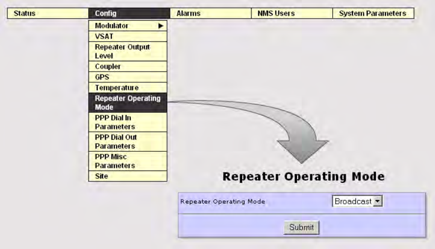
3EM21522AAAA OPERATION
Issue 1, March 2008 DTR-0200-SA-SIRIUS
5-37
Figure 5 - 44 Repeater Operating Mode Screen
5.7.2.1.1
Standby Mode
The Standby Mode is used to take the repeater off the air without removing all power.
The up-converter output is muted, ALC is off, and the HPA is switched off by dis-
abling the HPA power supply.
Following are the repeater operating conditions when in the Standby Mode:
• AC power is applied to the SPU, HPA, and fans
• HPA power supply is disabled
• HPA RF switch is off
• Up-converter output is muted
• Cabinet fans are turned on
5.7.2.1.2
Broadcast Mode
The Broadcast Mode is the normal operating mode for the repeater and allows the
repeater to transmit either real (satellite input) or internally generated test signals,
transmit OFDM signals for terrestrial broadcast, and run all the protection loops/
ALC. In this mode, all repeater functions are automatically maintained by the Main
Controller.

OPERATION 3EM21522AAAA
DTR-0200-SA-SIRIUS Issue 1, March 2008
5-38
5.7.2.1.3
Manual Mode
The Manual Mode is for testing and troubleshooting. Refer to the Maintenance sec-
tion of this manual for use of the Manual Mode. When switched to the Manual mode,
the repeater maintains all the system settings that were in effect in the previous
mode.
Table 5-1 summarizes the repeater status under the three modes of operation.
Table 5-1 Summary of Repeater Status Under the Three Modes of Operation
Standby Mode Broadcast Mode
(Real Signal) Broadcast Mode
(Test)) Manual Mode
Satellite Input On or Off On On or Off On or Off (if no satellite input)
Up Converter
Output Muted On On On
HPA RF Output Muted On On On or Off (user must turn HPA
on or off as required).
ALC Off On On Off
SPU AC & DC
Power On On On On
HPA AC & DC
Power Off On On On or Off
Fans Assemblies
(Rear door fans
will not operate
with cabinet rear
door open).
On On On On
IF Output On or Off
(depends on state
of modulator)
On On
On or Off
(user must unmute IF
as required).
GPS On or Off On On or Off On or Off
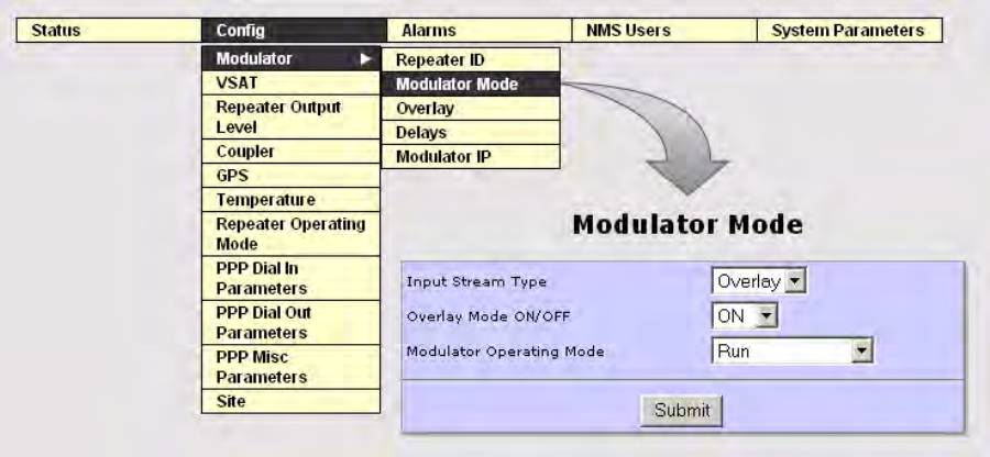
3EM21522AAAA OPERATION
Issue 1, March 2008 DTR-0200-SA-SIRIUS
5-39
5.7.2.2
Modulator Modes
There are seven modulator operating modes but only two are used in the field; the
remainder are factory modes. The two modes used by the operator/technician are:
1). Standby mode
2). Run
Mode selection is via the GUI Main Menu. From the Main Menu select Config =>Mod-
ulator => Modulator Mode => Standby or Run. See Figure 5 - 45.
Figure 5 - 45 Modulator Mode Screen
5.8
CONTROLS, INDICATORS, AND CONNECTORS
Controls, indicators, and connectors used in normal operation or referenced in proce-
dures are shown in Figure 5 - 46 through Figure 5 - 53.
5.8.1
Signal Processing Unit (SPU) Controls and Indicators
The SPU front panel has a series of LED indicators to warn of SPU Alarms, Sync con-
ditions, and HPA alarms and conditions. Specific alarms appear on the GUI ALARM
screen and are addressed in Appendices D and E. Also on the front panel is the Local
Remote push-button switch and its related indicator LEDs. Front panel indicators are
addressed in Figure 5 - 46.
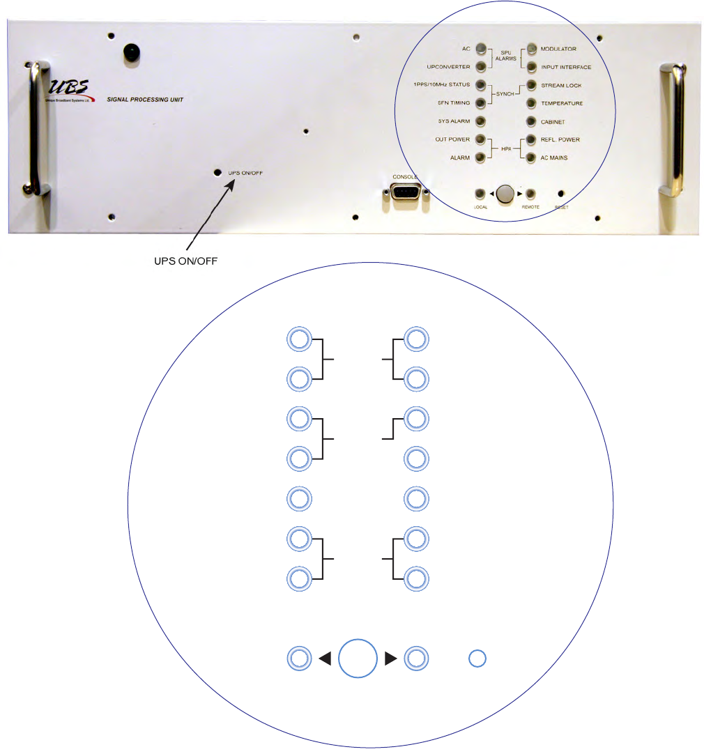
OPERATION 3EM21522AAAA
DTR-0200-SA-SIRIUS Issue 1, March 2008
5-40
Figure 5 - 46 Signal Processing Unit (SPU) Front Panel (Sheet 1 of 3)
SYS ALARM
OUT POWER
ALARM
CABINET
HPA
LOCAL REMOTE RESET
DTR-1039A
04/20/07
REFL Power
AC MAIN
AC
UPCONVERTER
SPU
ALARMS
MODULATION
INPUT INTERFACE
1PPS/10MHZ STATUS
SFN TIMING
SYNCH
STREAM LOCK
TEMPERATURE

3EM21522AAAA OPERATION
Issue 1, March 2008 DTR-0200-SA-SIRIUS
5-41
˙
Figure 5 - 46 Signal Processing Unit (SPU) Front Panel (Sheet 2 of 3)
SPU ALARMS
INDICATOR COMMENTS INDICATION
AC Fault occurs when 12 Vdc is out of limits Normal = Green
Fault Alarm = Red
MODULATOR Caused by any alarm from the modulator includ-
ing Communication error with the modulator Normal = Green
Fault Alarm = Red
UPCONVERTER This LED is red when there is a communication
error with the upconverter or the upconverter’s
LO PLL is not locked
Normal = Green
Fault Alarm = Red
INPUT INTERFACE VSAT Communication error or any error coming
from the VSAT Normal = Green
Fault Alarm = Red
SYNCHRONIZATION ALARMS
1 PPS/10MHz STATUS PLD not locked or 1PPS/10MHz alarms on the
modulator Normal = Green
Fault Alarm = Red
STREAM LOCK No lock to input stream alarm from the modulator Normal = Green
Fault Alarm = Red
SFN TIMING An alarm from the modulator indicating that the
Single Frequency Network margins are violated Normal = Green
Fault Alarm = Red
HPA ALARMS
OUT POWER HPA Forward Power Fault Normal = Green
Fault Alarm = Red
REFL POWER HPA Reflected power fault or Repeater Reflected
power fault Normal = Green
Fault Alarm = Red
ALARM Any alarm from the HPA will cause the LED to go
red Normal = Green
Fault Alarm = Red
AC MAINS Any summary alarm from the HPA power supply
modules will cause the LED to go red Normal = Green
Fault Alarm = Red

OPERATION 3EM21522AAAA
DTR-0200-SA-SIRIUS Issue 1, March 2008
5-42
Figure 5 - 46 Signal Processing Unit (SPU) Front Panel (Sheet 3 of 3)
5.8.2
High Power Amplifier (HPA) Controls and Indicators
5.8.2.1
The HPA front panel houses four status LEDs; AC ON, RF ON, DC ON, and SUM
FAULT. The panel also houses a type DB-9 RS-232 connector and a 15A Fuse Holder.
See
Figure 5 - 47
.
SUMMARY ALARMS
INDICATOR COMMENTS INDICATION
TEMPERATURE Alarm when Ambient temperature goes too high
over the Operating Temperature Threshold. Normal = Green
Fault Alarm = Red
SYS ALARM LED goes red for any alarm in the system Normal = Green
Fault Alarm = Red
CABINET Currently behaves the same way as Temperature
LED Normal = Green
Fault Alarm = Red
OTHER CONTROLS / CONNECTORS / INDICATORS
CONTROL/
CONNECTOR/
INDICATOR COMMENTS INDICATION
UPS ON/OF Push-button switch When the SPU is pow-
ered off, holding the
push-button keeps the
UPS off
CONSOLE RS-232 connector for external console
LOCAL/REMOTE Mode switch and mode indicators. Press twice to
switch to Local and disconnect the HPA Individual LEDs indicate
mode
RESET Push-button to reset controller
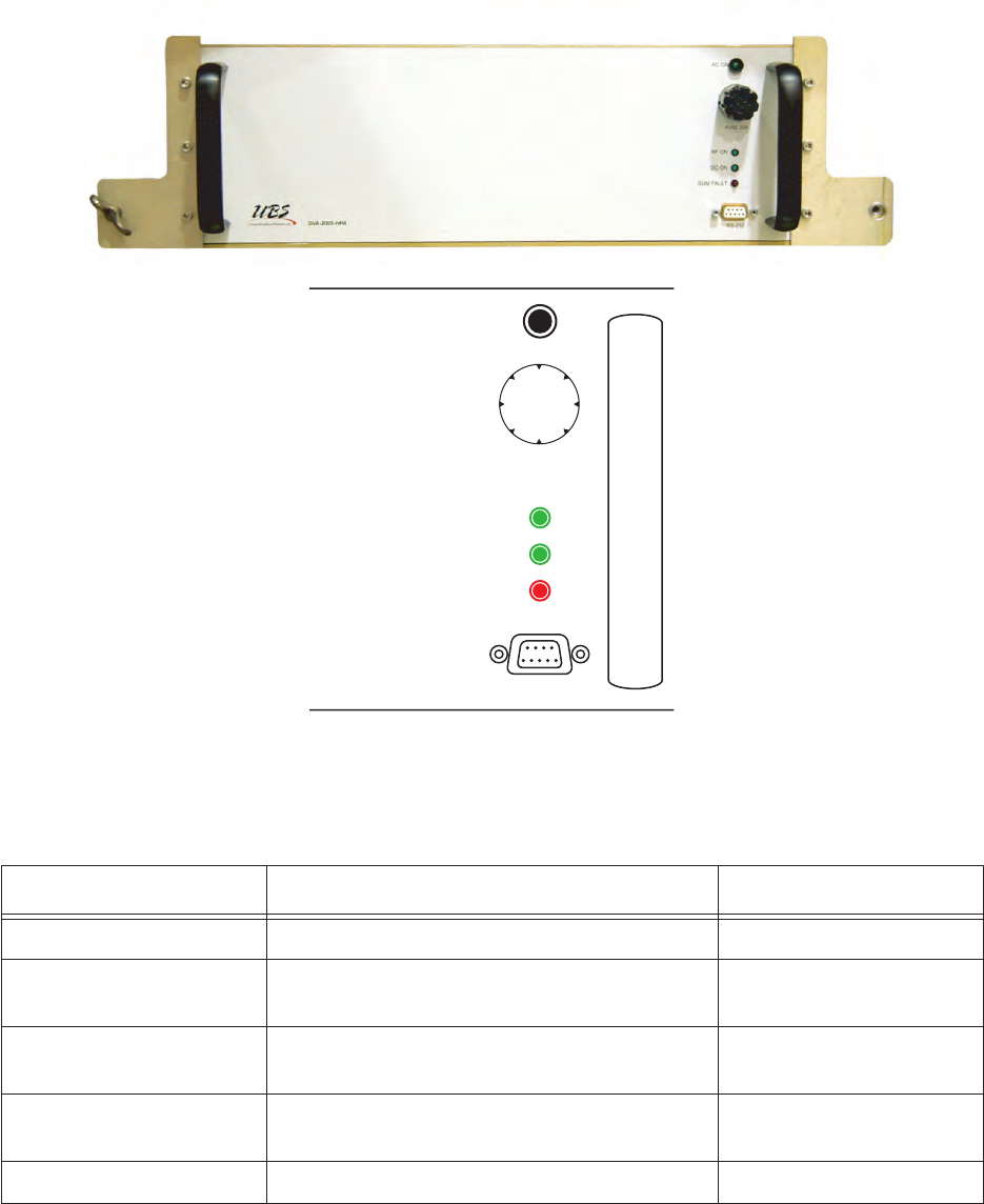
3EM21522AAAA OPERATION
Issue 1, March 2008 DTR-0200-SA-SIRIUS
5-43
Figure 5 - 47 HPA Front Panel
CONTROL/INDICATOR COMMENTS INDICATION
AC ON Indicates 204VAC into HPA power supply LED Green
RF ON HPA internal RF switch is enabled and RF
power is present at HPA output LED Green
DC ON HPA power supply is enabled and DC voltage
is applied to the amplifier LED Green
SUM FAULT Internal fault. Specific fault message sent via
RS-485 interface to Main Controller LED Red
(only on during fault)
RS-232 Future connecting point for external console
FUSE 20A
RF ON
DC ON
AC ON
RS-232 DTR-1042
08/08/07
SUM FAULT
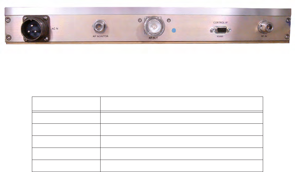
OPERATION 3EM21522AAAA
DTR-0200-SA-SIRIUS Issue 1, March 2008
5-44
5.8.2.2
The HPA rear panel houses five connectors; AC IN, RF MONITOR, RF OUT, CON-
TROL IF, and RF IN. See Figure 5 - 48.
Figure 5 - 48 HPA Rear Panel
CONNECTORS COMMENTS
AC IN Connects to PDU for AC power
RF MONITOR For monitoring/testing. Terminated with 50 ohm load
RF OUT Connects to output bandpass filter
CONTROL I/F Connects to Main Controller PA Control connector
RF IN Connects to Up-Converter RF OUT connector
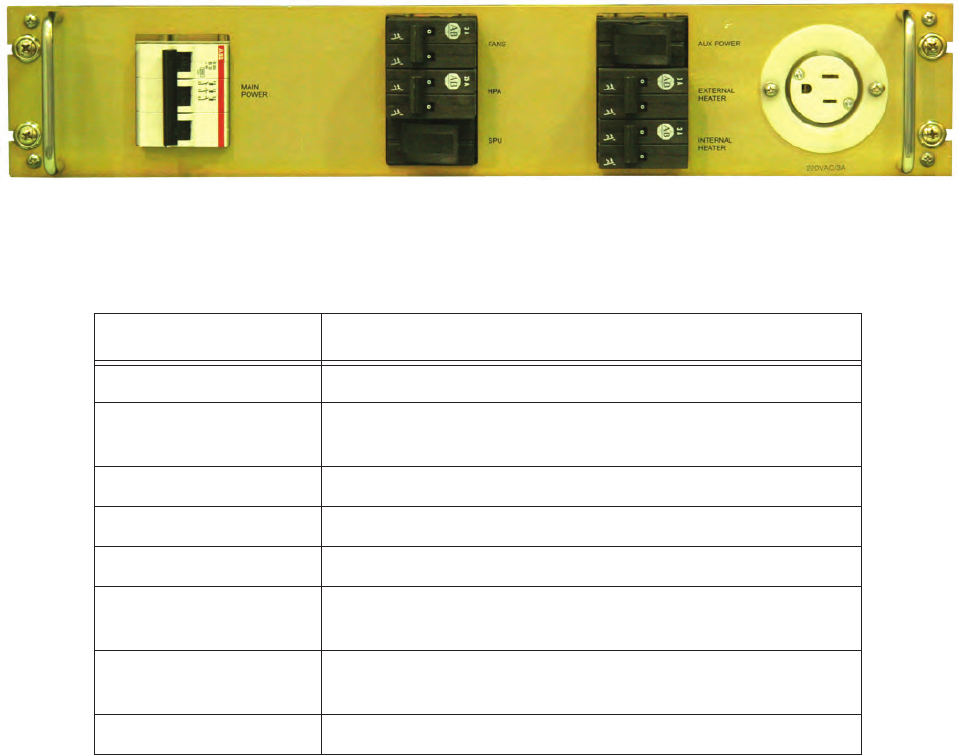
3EM21522AAAA OPERATION
Issue 1, March 2008 DTR-0200-SA-SIRIUS
5-45
5.8.3
Power Distribution Unit (PDU) Front Panel Controls
The PDU front panel houses seven circuit breakers for controlling repeater electrical
power. There is also an auxiliary power receptacle for future use. See Figure 5 - 49.
Figure 5 - 49 Power Distribution Unit Front Panel
CONTROL COMMENTS
MAIN POWER Removes all power from the entire repeater cabinet.
FANS Removes power from the four axial fans; two on the top of
the HPA and two on the back door of the cabinet.
HPA Removes input power from the HPA drawer.
SPU Removes input power from the SPU drawer.
AUX POWER Removes power from the AUX receptacle.
EXTERNAL HEATER This is an optional connection for use by the customer as
desired.
INTERNAL HEATER Removes power from the SPU area heater. The heater is
not part of the SPU.
AUX OUTLET Controlled by AUX POWER CB. Supplies 120v, 5A.
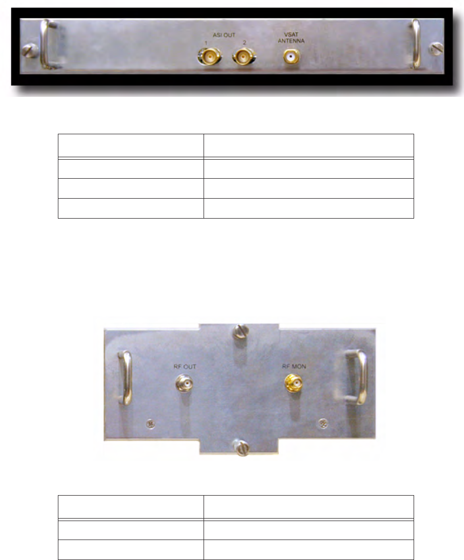
OPERATION 3EM21522AAAA
DTR-0200-SA-SIRIUS Issue 1, March 2008
5-46
5.8.4
VSAT Receiver Rear Panel Connectors
The
VSAT
Receiver rear panel has three connectors;
ASI OUT 1, ASI OUT
2, and
VSAT ANTENNA
. See Figure 5 - 50.
Figure 5 - 50 VSAT Receiver Rear Panel
5.8.5
Up-Converter Rear Panel Connectors
The Up-converter rear panel has two connectors;
RF OUT
and
RF MON
. See Figure 5 - 51.
Figure 5 - 51 Up-Converter Rear Panel
CONNECTOR COMMENTS
ASI OUT 1 Not connected
ASI OUT 2 Connects to ASI B on Main Controller
VSAT ANTENNA Connects to VSAT antenna signal cable
CONNECTOR COMMENTS
RF OUT Connects to HPA RF IN
RF MON Not connected
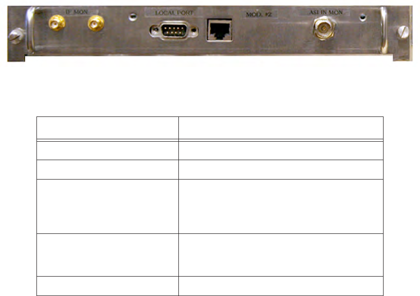
3EM21522AAAA OPERATION
Issue 1, March 2008 DTR-0200-SA-SIRIUS
5-47
5.8.6
Modulator Rear Panel Connectors
The Modulator rear panel has five connectors;
IF MON I, IF MON Q, LOCAL PORT,
ETHERNET
, and
ASI IN MON
. See Figure 5 - 52.
Figure 5 - 52 Modulator Rear Panel
CONNECTOR COMMENTS
IF MON I Not connected
IF MON Q Not connected
LOCAL PORT RS-232 Serial Port (DB9 connector) for PC
direct connection to Modulator via null
modem cable. Used to access parameters
and status via CLI protocol.
ETHERNET Connects to Main Controller ETHERNET
connection to allow communication between
Main Controller and Modulator.
ASI IN MON Not connected
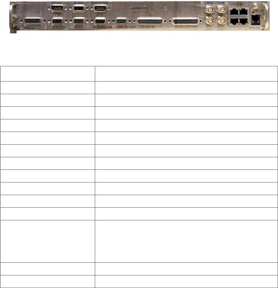
OPERATION 3EM21522AAAA
DTR-0200-SA-SIRIUS Issue 1, March 2008
5-48
5.8.7
Main Controller Rear Panel Connectors
The Main Controller rear panel has 20 connectors;
MODEM
, spare (3),
FWD RF
DETECTOR, REFL RF DETECTOR, PA CONTROL, TEMP.SENSOR, STATUS IN,
RELAY CONTROL, 10MHZ, 1PPS, ASI A, ASI B, ETHERNET 10/100/1000 BASE T (4),
GPS ANT, DIAL-UP
. See Figure 5 - 53.
Figure 5 - 53 Main Controller Rear Panel
CONNECTOR COMMENTS
MODEM Not connected
FWD RF DETECTOR Connects to RF forward power detector for RF monitoring
REFL. RF DETECTOR Connects to RF reflected power detector for RF monitoring
PA CONTROL Connects to HPA Control I/F
TEMP.SENSOR Connects to PDU
STATUS IN Connected to Status Cable inside repeater and indicates Door Status
RELAY CONTROL
Connected to Relay Cable inside repeater and indicates Relay Status
10 MHZ Not connected
1 PPS Not connected
ASI A Not connected
ASI B Connected to VSAT RX ASI OUT 2
ETHERNET 10/100 BASE T There are four Ethernet connectors. Any one of the four must connect
by cable to the Modulator back panel Ethernet connector. This pro-
vides communication between the Modulator and Main Controller.
The remaining three Ethernet connectors connect to external equip-
ment such as a PC (for troubleshooting, parameter monitoring, etc.).
GPS ANT Connects to GPS Antenna cable.
DIAL-UP Phone cable connection