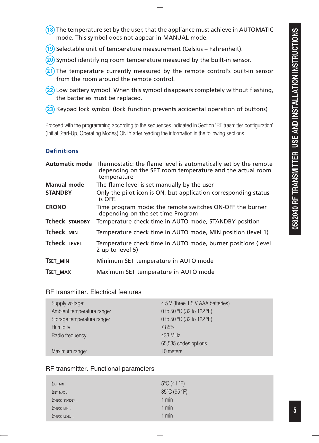
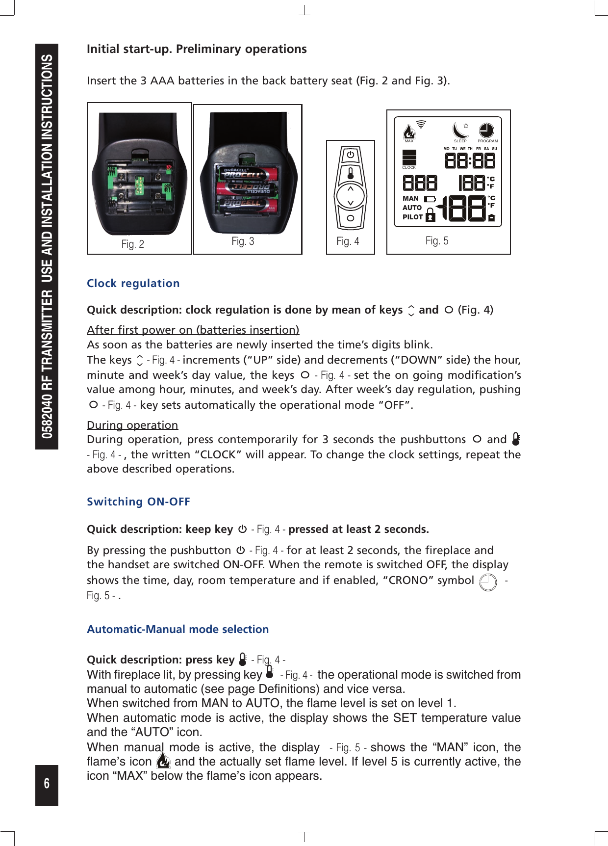
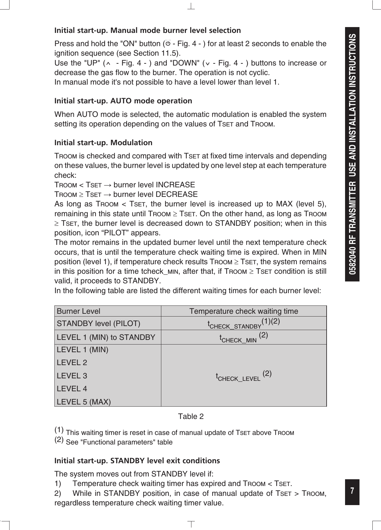
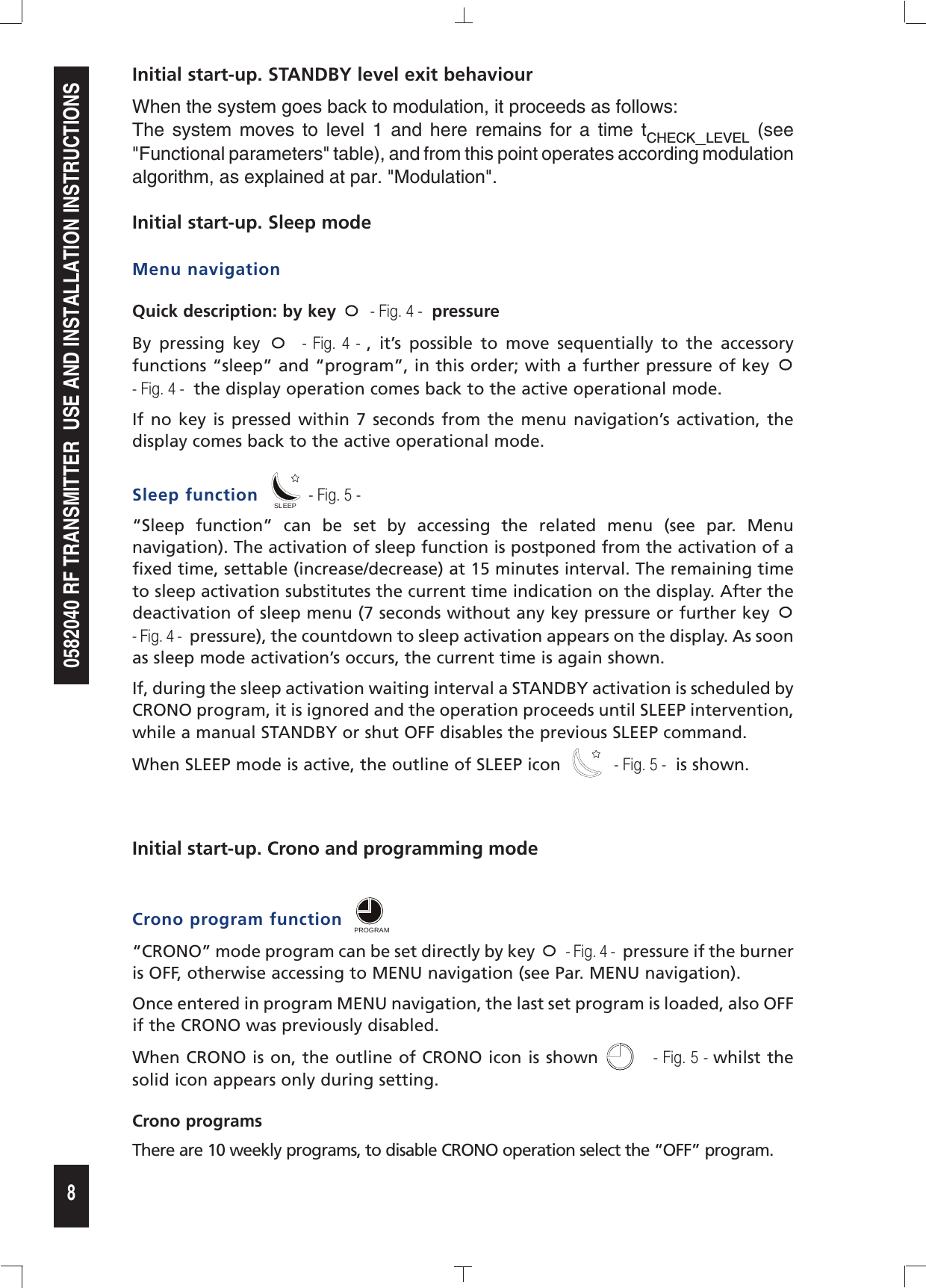
Sit La Precisa S p A 0582040 Remote Control Transmitter User Manual

Sit La Precisa S.p.A. Remote Control Transmitter

User Manual

grazieamoregraziegrazieamoregraziegrazieamoregraziegrazieamoregraziegrazieamoregraziegrazieamoregraziegrazieamoregrazie9.957.109   01        DATE: May ,02, 20120582040 RF TRANSMITTERUSE AND INSTALLATION INSTRUCTIONSRead the instructions before using the device. This control must be installed in compliance with current legislationSIT La Precisa S.p.A.Viale dell’Industria 31-3335129 PADOVA - ITALY
grazieamoregraziegrazieamoregraziegrazieamoregraziegrazieamoregraziegrazieamoregraziegrazieamoregraziegrazieamoregrazie0582040 RF TRANSMITTER  USE AND INSTALLATION INSTRUCTIONS2FOREWORDIntroduction to the manualThe purpose of this manual is to provide the information you need to install and use this product properly and safely.This information is the outcome  of ongoing, systematic data processing and technical tests recorded and validated by the Manufacturer, in compliance with its in-house information quality and safety procedures.The  contents  of  this  manual  are  intended  exclusively  for  skilled,  informed  and  trained  users,  capable  of operating in conditions that are safe for people, the system and the environment, and fully compliant with the requirements discussed in the following pages and in current occupational health and safety legislation.The information concerning assembly/installation, servicing, replacement and repair is intended for authorized and skilled technicians, who are always the only people allowed to carry out said activities.For the proper handling of the system, it is essential to ensure the readability and proper preservation of this manual, also for future reference. Contact the Manufacturer directly in the event of its deterioration, or to ask for any further technical and operational information you may need.The text, descriptions, images, examples and all other details contained in this document are the exclusive property of the Manufacturer. All rights reserved. Product descriptionThe RF handset is a remote control based on RF transmission, specifically designed to operate in combination with a specific RF receiver module.SYSTEM IDENTIFICATION0582012, RF receiver: 0582040,  RF transmitter:NOTE: when placing the RF receiver module, it is recommended to straighten the antenna as much as possible by keeping it as far as possible from metallic surfaces.CAUTION! It is strictly forbidden to remove or damage the labels. Where necessary, have them replaced urgently and exclusively by the Manufacturer.For any information and/or technical needs relating to the use and servicing of the device, always provide the following preliminary details:-  Product code-  Product revision-  Date of manufactureExample: -  0584040-  Revision: 00;-  Date of manufacture: : 12 - 06;-  Date of issue of the manual (as shown on the cover).The devices in the "582” Series are manufactured by SIT La Precisa. Any, even partial reproduction of the product, auxiliary assemblies and accompanying documentation is strictly forbidden.829 NOVA millivoltCombination Gas Control PROFLAMETransmitter PROFLAME Receiver PROFLAME FMC820 NOVA millivolt HI-LOWCombination Gas ControlRF REMOTE CONTROLRF RECEIVER
0582040 RF TRANSMITTER  USE AND INSTALLATION INSTRUCTIONSgrazieamoregraziegrazieamoregraziegrazieamoregraziegrazieamoregraziegrazieamoregraziegrazieamoregraziegrazieamoregrazieFig. 1: RF Remote Control3RF Remote ControlSee Fig. 1 and the table 1:1 Position of room temperature sensor2 LCD display3 ON-OFF/PILOT Key4 MANUAL-AUTOMATIC Key5 UP-DOWN arrow Key6 FUNCTION (SLEEP-PROGRAM)(*) Key or keyboard lock-release(**)7 Base and battery compartment712345' 65Ref. Icon Description3MAXCLOCKMANAUTOPILOTSLEEP PROGRAMON-OFF/PILOT4MAXCLOCKMANAUTOPILOTSLEEP PROGRAMMANUAL-AUTOMATIC mode5MAXCLOCKMANAUTOPILOTSLEEP PROGRAMIncrease 5'MAXCLOCKMANAUTOPILOTSLEEP PROGRAMDecrease6MAXCLOCKMANAUTOPILOTSLEEP PROGRAMSLEEP-PROGRAM mode (*)Keyboard lock-release (**)Table. 1: RF Control panel keyboardNote: when RF remote is associated to BIC 05844XX, where Direct Burner Ignition is present, PILOT position of the remote is equivalent to OFF position for the application.(*)The button (6) moves between SLEEPand PROGRAM and with a thirth pressure ot the button return into previous status ( MANUAL o AUTO).(*)See Initial start-up. Keyboard lock-unlock at page 9.
grazieamoregraziegrazieamoregraziegrazieamoregraziegrazieamoregraziegrazieamoregraziegrazieamoregraziegrazieamoregrazie0582040 RF TRANSMITTER  USE AND INSTALLATION INSTRUCTIONS48 Functioning mode symbols (MANUAL - THERMOSTATIC - PILOT).9 Digits identifying the weekly TIMER program currently selected.10  Clock  setting  symbol.  When  this  symbol  appears,  you  can  adjust  the  clock setting displayed by the digits. 11  Flame power bars: 1 bar = level 1, 2 bar = level 2, 3 bar = level 3, 4 bar = level 4, 5 bar = level maximum. These bars appear only in manual mode.12  Flame symbol, indicating the current flame power. If flame power is at level 5, the MAX message appears.13  Symbol for data transmission to receiver14  SLEEP function symbol. If this symbol does not appear, the SLEEP function is not active. If only the outline of the symbol appears, the SLEEP function is active, meaning that the appliance will switch off at the end of the countdown period set by the user and shown by symbol 17. A solid black symbol indicates that you are in the SLEEP setting menu .15  TIMER symbol. If this symbol does not appear, the TIMER is not active. If only the  outline  of  the  symbol appears,  the  TIMER  is  active. A  solid  black  symbol indicates that you are in the TIMER setting menu.16  Symbols indicating the current day.17 Internal clock. The clock functions as a countdown when the SLEEP function is selected .MAXCLOCKMANAUTOPILOTSLEEP PROGRAM812212091013 14 151617181919112223LCD Display
0582040 RF TRANSMITTER  USE AND INSTALLATION INSTRUCTIONSgrazieamoregraziegrazieamoregraziegrazieamoregraziegrazieamoregraziegrazieamoregraziegrazieamoregraziegrazieamoregrazie518  The temperature set by the user, that the appliance must achieve in AUTOMATIC mode. This symbol does not appear in MANUAL mode.19  Selectable unit of temperature measurement (Celsius – Fahrenheit).20  Symbol identifying room temperature measured by the built-in sensor.21  The  temperature  currently  measured  by  the  remote  control’s  built-in  sensor from the room around the remote control.22  Low battery symbol. When this symbol disappears completely without flashing, the batteries must be replaced.23  Keypad lock symbol (lock function prevents accidental operation of buttons)Proceed with the programming according to the sequences indicated in Section "RF trasmitter configuration" (Initial Start-Up, Operating Modes) ONLY after reading the information in the following sections.RF transmitter. Electrical featuresSupply voltage:         4.5 V (three 1.5 V AAA batteries)Ambient temperature range:      0 to 50 °C (32 to 122 °F)Storage temperature range:      0 to 50 °C (32 to 122 °F)Humidity          ≤ 85%Radio frequency:        433 MHz              65,535 codes optionsMaximum range:         10 metersRF transmitter. Functional parameterstset_min :           5°C (41 °F)tset_max ::          35°C (95 °F)tcheck_standby :          1 mintcheck_min :          1 mintcheck_level :          1 minDefinitionsAutomatic mode  Thermostatic: the flame level is automatically set by the remote depending on the SET room temperature and the actual room temperatureManual mode  The flame level is set manually by the userSTANDBY  Only the pilot icon is ON, but application corresponding status is OFF.CRONO  Time program mode: the remote switches ON-OFF the burner depending on the set time Program Tcheck_standby Temperature check time in AUTO mode, STANDBY positionTcheck_min Temperature check time in AUTO mode, MIN position (level 1)Tcheck_level Temperature check time in AUTO mode, burner positions (level    2 up to level 5)Tset_min Minimum SET temperature in AUTO modeTset_max Maximum SET temperature in AUTO mode
grazieamoregraziegrazieamoregraziegrazieamoregraziegrazieamoregraziegrazieamoregraziegrazieamoregraziegrazieamoregrazie0582040 RF TRANSMITTER  USE AND INSTALLATION INSTRUCTIONS6Initial start-up. Preliminary operationsInsert the 3 AAA batteries in the back battery seat (Fig. 2 and Fig. 3).Fig. 2 Fig. 3 MAXCLOCKMANAUTOPILOTSLEEP PROGRAMFig. 4 MAXCLOCKMANAUTOPILOTSLEEP PROGRAMFig. 5Clock regulationQuick description: clock regulation is done by mean of keys MAXCLOCKMANAUTOPILOTSLEEP PROGRAM and MAXCLOCKMANAUTOPILOTSLEEP PROGRAM (Fig. 4)After first power on (batteries insertion) As soon as the batteries are newly inserted the time’s digits blink.The keys MAXCLOCKMANAUTOPILOTSLEEP PROGRAM - Fig. 4 - increments (“UP” side) and decrements (“DOWN” side) the hour, minute and week’s day value, the keys MAXCLOCKMANAUTOPILOTSLEEP PROGRAM - Fig. 4 - set the on going modification’s value among hour, minutes, and week’s day. After week’s day regulation, pushing MAXCLOCKMANAUTOPILOTSLEEP PROGRAM - Fig. 4 - key sets automatically the operational mode “OFF”.During operationDuring  operation,  press  contemporarily  for  3 seconds  the pushbuttons MAXCLOCKMANAUTOPILOTSLEEP PROGRAM  and MAXCLOCKMANAUTOPILOTSLEEP PROGRAM - Fig. 4 - , the written “CLOCK” will appear. To change the clock settings, repeat the above described operations.Switching ON-OFFQuick description: keep key MAXCLOCKMANAUTOPILOTSLEEP PROGRAM - Fig. 4 - pressed at least 2 seconds.By pressing the pushbutton MAXCLOCKMANAUTOPILOTSLEEP PROGRAM - Fig. 4 - for at least 2 seconds, the fireplace and the handset are switched ON-OFF. When the remote is switched OFF, the display shows the time, day, room temperature and if enabled, “CRONO” symbol MAXCLOCKMANAUTOPILOTSLEEP PROGRAM - Fig. 5 - .Automatic-Manual mode selectionQuick description: press key MAXCLOCKMANAUTOPILOTSLEEP PROGRAM - Fig. 4 - With fireplace lit, by pressing key MAXCLOCKMANAUTOPILOTSLEEP PROGRAM  - Fig. 4 -  the operational mode is switched from manual to automatic (see page Definitions) and vice versa. When switched from MAN to AUTO, the flame level is set on level 1. When automatic mode is active, the display shows the SET temperature value and the “AUTO” icon.When  manual  mode  is  active,  the  display   -  Fig.  5  - shows  the  “MAN”  icon,  the flame’s icon MAXCLOCKMANAUTOPILOTSLEEP PROGRAM and the actually set flame level. If level 5 is currently active, the icon “MAX” below the flame’s icon appears.
0582040 RF TRANSMITTER  USE AND INSTALLATION INSTRUCTIONSgrazieamoregraziegrazieamoregraziegrazieamoregraziegrazieamoregraziegrazieamoregraziegrazieamoregraziegrazieamoregrazie7Initial start-up. Manual mode burner level selectionPress and hold the "ON" button (MAXCLOCKMANAUTOPILOTSLEEP PROGRAM - Fig. 4 - ) for at least 2 seconds to enable the ignition sequence (see Section 11.5).Use the "UP" (MAXCLOCKMANAUTOPILOTSLEEP PROGRAM  - Fig. 4 - ) and "DOWN" (MAXCLOCKMANAUTOPILOTSLEEP PROGRAM - Fig. 4 - ) buttons to increase or decrease the gas flow to the burner. The operation is not cyclic.In manual mode it's not possible to have a level lower than level 1.Initial start-up. AUTO mode operationWhen AUTO mode is selected, the automatic modulation is enabled the system setting its operation depending on the values of Tset and Troom. Initial start-up. ModulationTroom is checked and compared with Tset at fixed time intervals and depending on these values, the burner level is updated by one level step at each temperature check:Troom < Tset → burner level INCREASETroom ≥ Tset → burner level DECREASEAs  long  as  Troom  <  Tset,  the  burner  level  is  increased  up  to  MAX  (level  5), remaining in this state until Troom ≥ Tset. On the other hand, as long as Troom ≥ Tset, the burner level is decreased down to STANDBY position; when in this position, icon “PILOT” appears. The motor remains in the updated burner level until the next temperature check occurs, that is until the temperature check waiting time is expired. When in MIN position (level 1), if temperature check results Troom ≥ Tset, the system remains in this position for a time tcheck_min, after that, if Troom ≥ Tset condition is still valid, it proceeds to STANDBY.In the following table are listed the different waiting times for each burner level:Burner Level Temperature check waiting time STANDBY level (PILOT) tcheck_standby(1)(2) LEVEL 1 (MIN) to STANDBY tcheck_min (2)LEVEL 1 (MIN) LEVEL 2LEVEL 3LEVEL 4LEVEL 5 (MAX)tcheck_level (2)                Table 2(1) This waiting timer is reset in case of manual update of Tset above Troom(2) See "Functional parameters" tableInitial start-up. STANDBY level exit conditionsThe system moves out from STANDBY level if:1)  Temperature check waiting timer has expired and Troom < Tset.2)  While in  STANDBY position, in case  of manual update of Tset > Troom, regardless temperature check waiting timer value.
grazieamoregraziegrazieamoregraziegrazieamoregraziegrazieamoregraziegrazieamoregraziegrazieamoregraziegrazieamoregrazie0582040 RF TRANSMITTER  USE AND INSTALLATION INSTRUCTIONS8Initial start-up. STANDBY level exit behaviourWhen the system goes back to modulation, it proceeds as follows:The  system  moves  to  level  1  and  here  remains  for  a  time  tcheck_level  (see "Functional parameters" table), and from this point operates according modulation algorithm, as explained at par. "Modulation". Initial start-up. Sleep modeMenu navigationQuick description: by key MAXCLOCKMANAUTOPILOTSLEEP PROGRAM  - Fig. 4 -  pressureBy  pressing  key MAXCLOCKMANAUTOPILOTSLEEP PROGRAM  -  Fig.  4  - ,  it’s  possible  to  move  sequentially  to  the  accessory functions “sleep” and “program”, in this order; with a further pressure of key MAXCLOCKMANAUTOPILOTSLEEP PROGRAM  - Fig. 4 -  the display operation comes back to the active operational mode.If  no  key  is  pressed  within 7  seconds from the  menu  navigation’s  activation,  the display comes back to the active operational mode.Sleep function  MAXCLOCKMANAUTOPILOTSLEEP PROGRAM - Fig. 5 - “Sleep  function”  can  be  set  by  accessing  the  related  menu  (see  par.  Menu navigation). The activation of sleep function is postponed from the activation of a fixed time, settable (increase/decrease) at 15 minutes interval. The remaining time to sleep activation substitutes the current time indication on the display. After the deactivation of sleep menu (7 seconds without any key pressure or further key MAXCLOCKMANAUTOPILOTSLEEP PROGRAM  - Fig. 4 -  pressure), the countdown to sleep activation appears on the display. As soon as sleep mode activation’s occurs, the current time is again shown.If, during the sleep activation waiting interval a STANDBY activation is scheduled by CRONO program, it is ignored and the operation proceeds until SLEEP intervention, while a manual STANDBY or shut OFF disables the previous SLEEP command.When SLEEP mode is active, the outline of SLEEP icon  MAXCLOCKMANAUTOPILOTSLEEP PROGRAM  - Fig. 5 -  is shown.Initial start-up. Crono and programming modeCrono program function  MAXCLOCKMANAUTOPILOTSLEEP PROGRAM“CRONO” mode program can be set directly by key MAXCLOCKMANAUTOPILOTSLEEP PROGRAM  - Fig. 4 -  pressure if the burner is OFF, otherwise accessing to MENU navigation (see Par. MENU navigation).Once entered in program MENU navigation, the last set program is loaded, also OFF if the CRONO was previously disabled.When CRONO is on, the outline of CRONO icon is shown MAXCLOCKMANAUTOPILOTSLEEP PROGRAM  - Fig. 5 - whilst the solid icon appears only during setting.Crono programs There are 10 weekly programs, to disable CRONO operation select the “OFF” program.
0582040 RF TRANSMITTER  USE AND INSTALLATION INSTRUCTIONSgrazieamoregraziegrazieamoregraziegrazieamoregraziegrazieamoregraziegrazieamoregraziegrazieamoregraziegrazieamoregrazie9N° Program Type DaysMon - FriSat - SunMon - FriSat - SunMon - FriSat - SunMon - Sat SunMon - Sat SunMon - FriSat - SunMon - FriSat - SunMon - FriSat - SunMon - FriSat - SunFriSat - SunONOFFWeekly ProgramsP10 Week-EndP09 Workman / ClerkP08 Workman / ClerkP07 Workman / ClerkP06 Workman / ClerkP05 ShopkeeperP04 ShopkeeperP03 ShopP02 Shift worker8.00 PM9.00 PM10.00 PM11.00 PM12.00 AMP01 Householder2.00 PM3.00 PM4.00 PM5.00 PM6.00 PM7.00 PM8.00 AM9.00 AM10.00 AM11.00 AM12.00 PM1.00 PMWeekly program Timetable12.00 AM1.00 AM2.00 AM3.00 AM4.00 AM5.00 AM6.00 AM7.00 AMInitial start-up. Keyboard lock-unlockBy  keeping  pressed  “O”  key  al  least  for  5  seconds,  the  keyboard  is  locked-unlocked. The locking icon appears: MAXCLOCKMANAUTOPILOTSLEEP PROGRAMInitial start-up. °C-°FWith remote OFF, keeping pressed “MAXCLOCKMANAUTOPILOTSLEEP PROGRAM” key at least for 5 seconds, the temperature unit changes from Celsius to Fahrenheit degrees and vice versa.Initial start-up. Battery level indicationWhen the batteries have to be changed, the related icon appears: MAXCLOCKMANAUTOPILOTSLEEP PROGRAM Shutdown procedureIn RUN mode, when the remote MAXCLOCKMANAUTOPILOTSLEEP PROGRAM button is pressed for a time < 1 second, the system goes to "PILOT" status.
10grazieamoregraziegrazieamoregraziegrazieamoregraziegrazieamoregraziegrazieamoregraziegrazieamoregraziegrazieamoregrazie0582040 RF TRANSMITTER  USE AND INSTALLATION INSTRUCTIONSRegulatory Compliance (FCC)This equipment has been tested and found to comply with Part 15 of the FCC Rules. NOTE: Any changes or modification not approved by SIT LA PRECISA S.p.A. could void the user’s authority to operate the equipment.
110582040 RF TRANSMITTER  USE AND INSTALLATION INSTRUCTIONSgrazieamoregraziegrazieamoregraziegrazieamoregraziegrazieamoregraziegrazieamoregraziegrazieamoregraziegrazieamoregrazieTHIS PAGE IS INTENTIONALLY LEFT BLANK
grazieamoregraziegrazieamoregraziegrazieamoregraziegrazieamoregraziegrazieamoregraziegrazieamoregraziegrazieamoregrazie0582040 RF TRANSMITTER  USE AND INSTALLATION INSTRUCTIONS

Navigation menu