SofaWare Technologies SBX-11GWLAN-7 Safe@office/VPN-1 Edge User Manual Check Point Safe Office User Guide
SofaWare Technologies Ltd. Safe@office/VPN-1 Edge Check Point Safe Office User Guide
UserManual.wiki
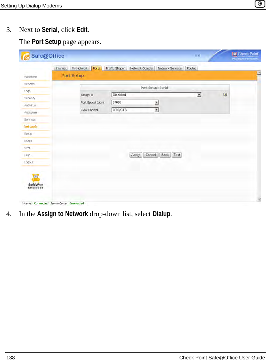
>
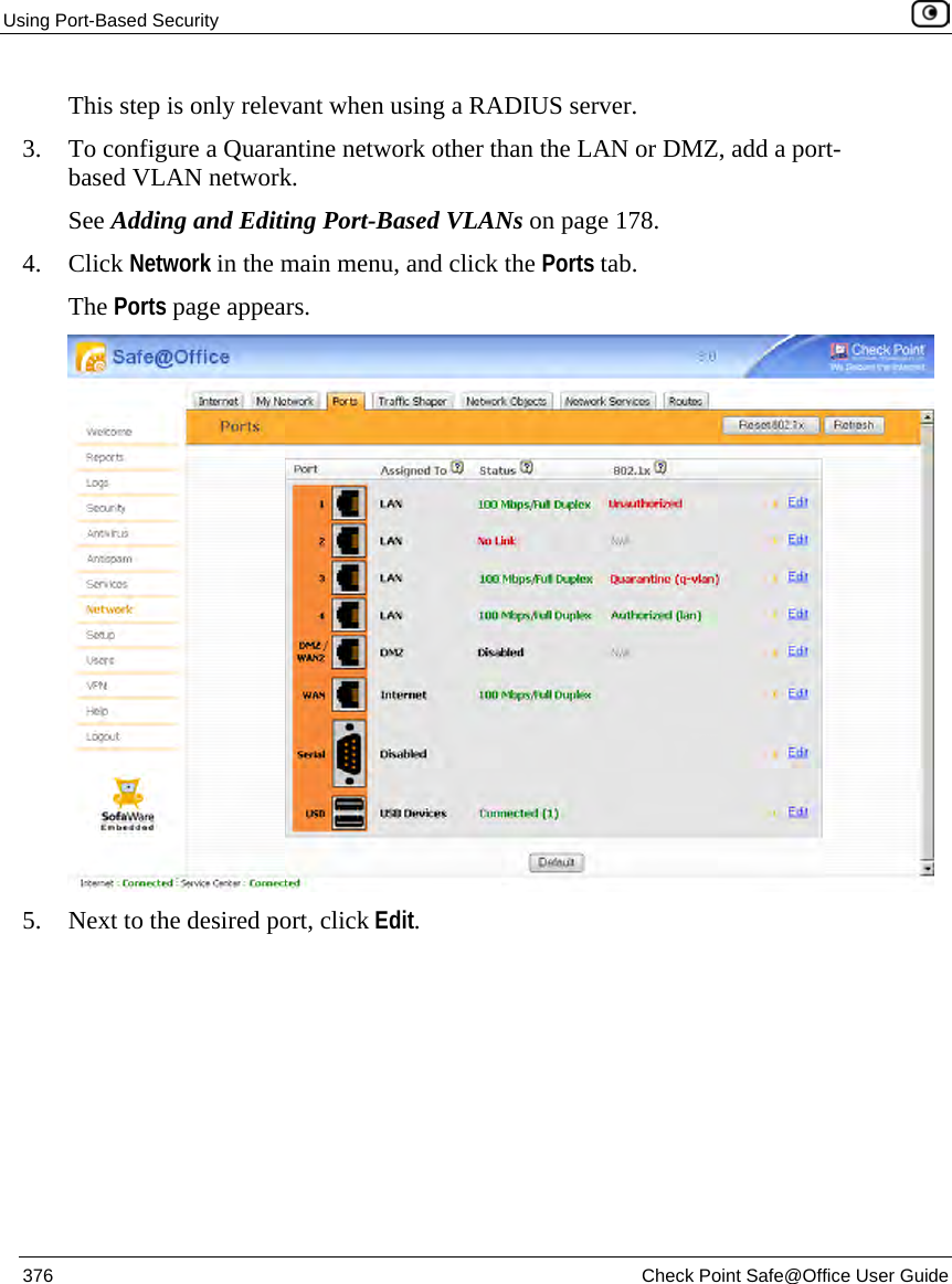
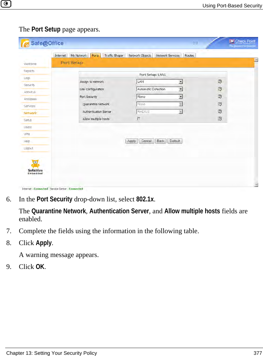
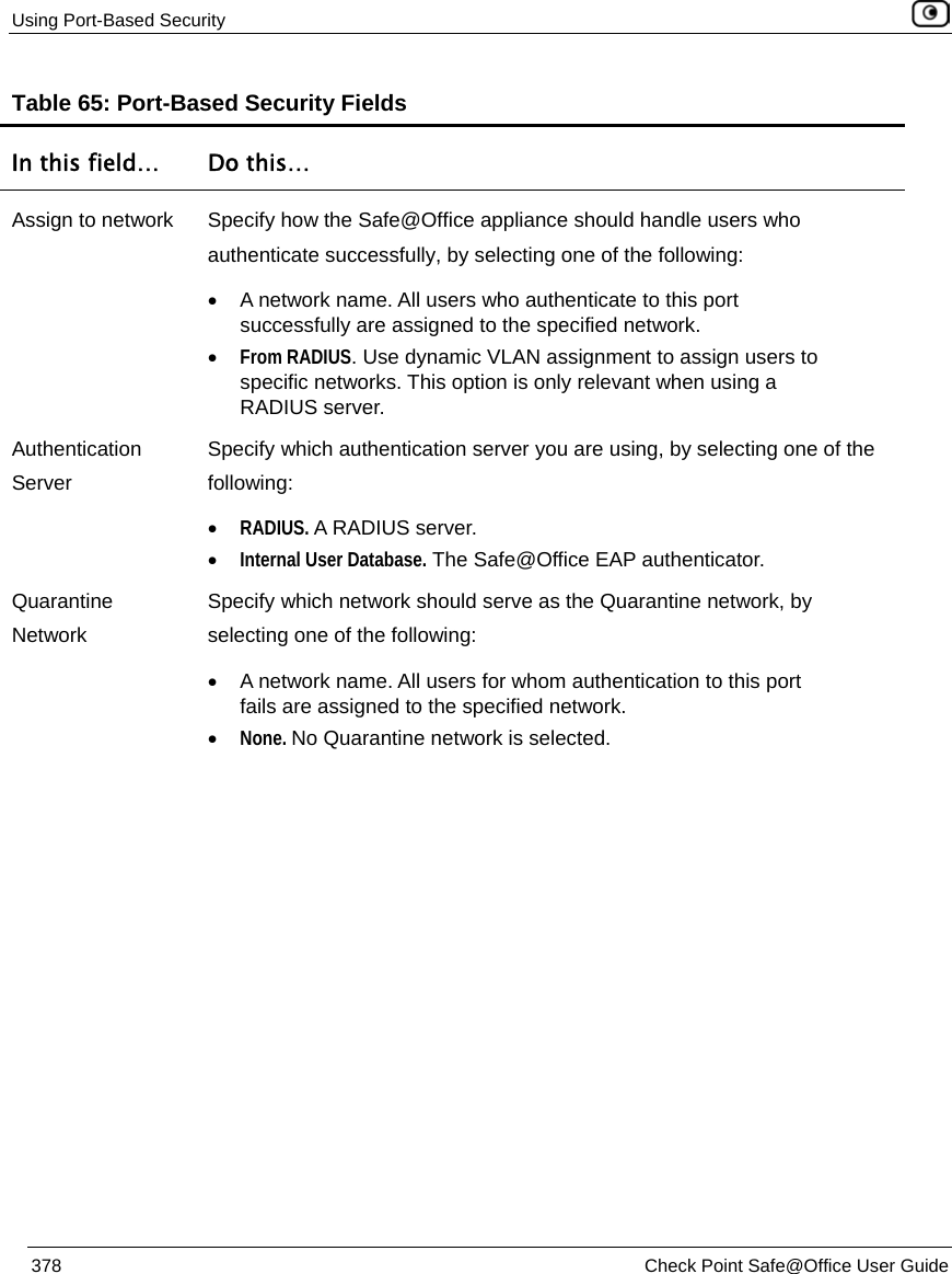
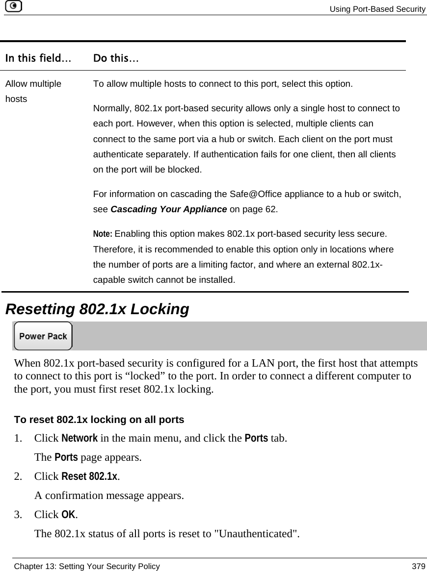
SofaWare Technologies
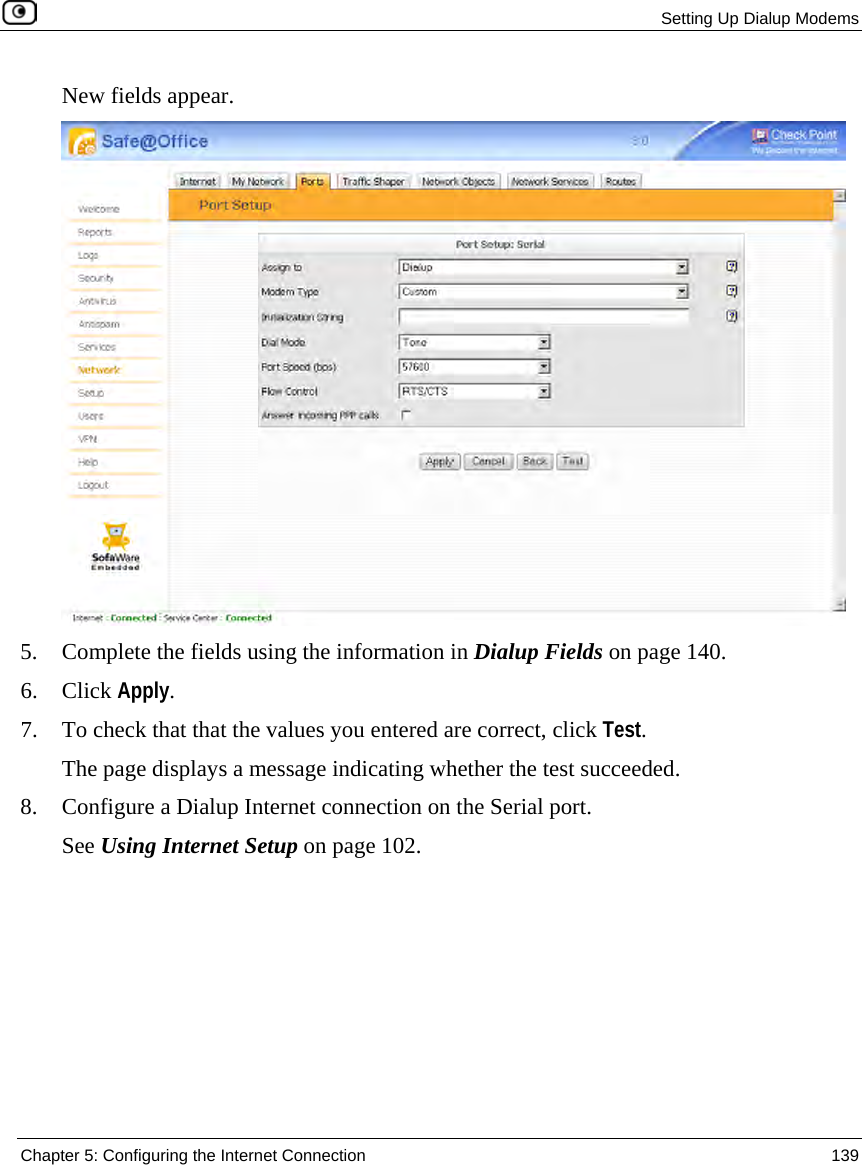
>
SBX-11GWLAN-7 User Manual
>
manual part 1
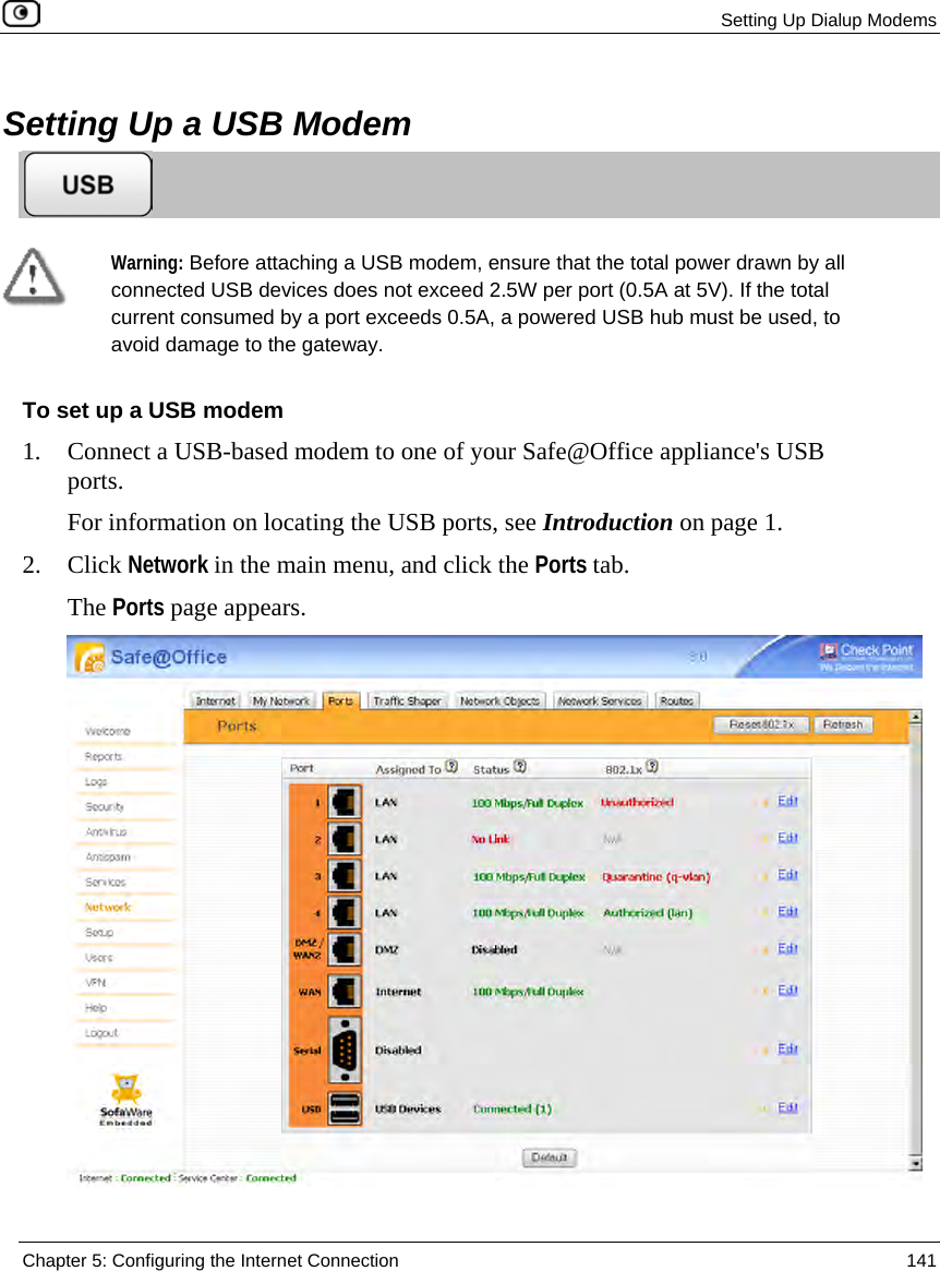
Contents
1.
manual part 1
2.
manual part 2
manual part 1
Navigation menu
Upload a User Manual
Namespaces
Wiki Guide
HTML
PDF
Info
Views
User Manual
Discussion / Help
Navigation


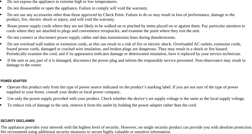
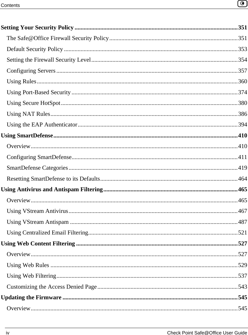


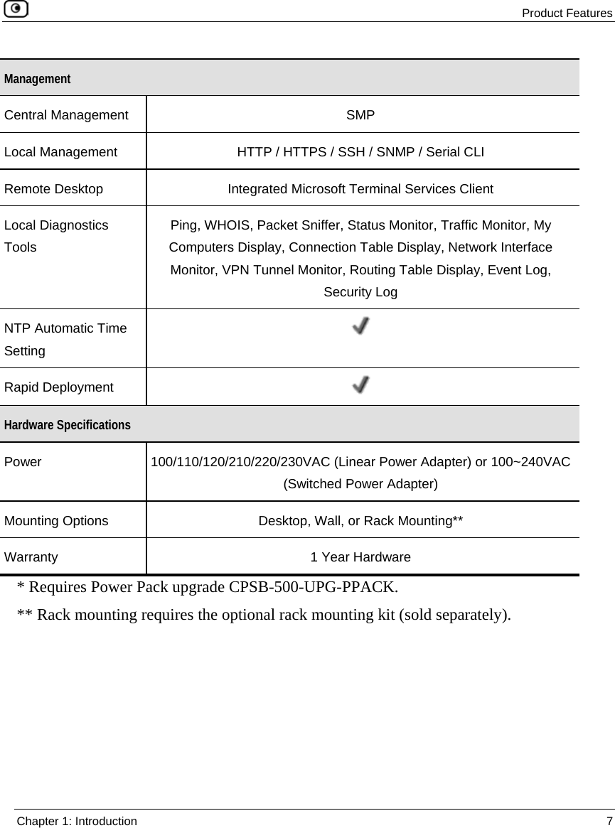
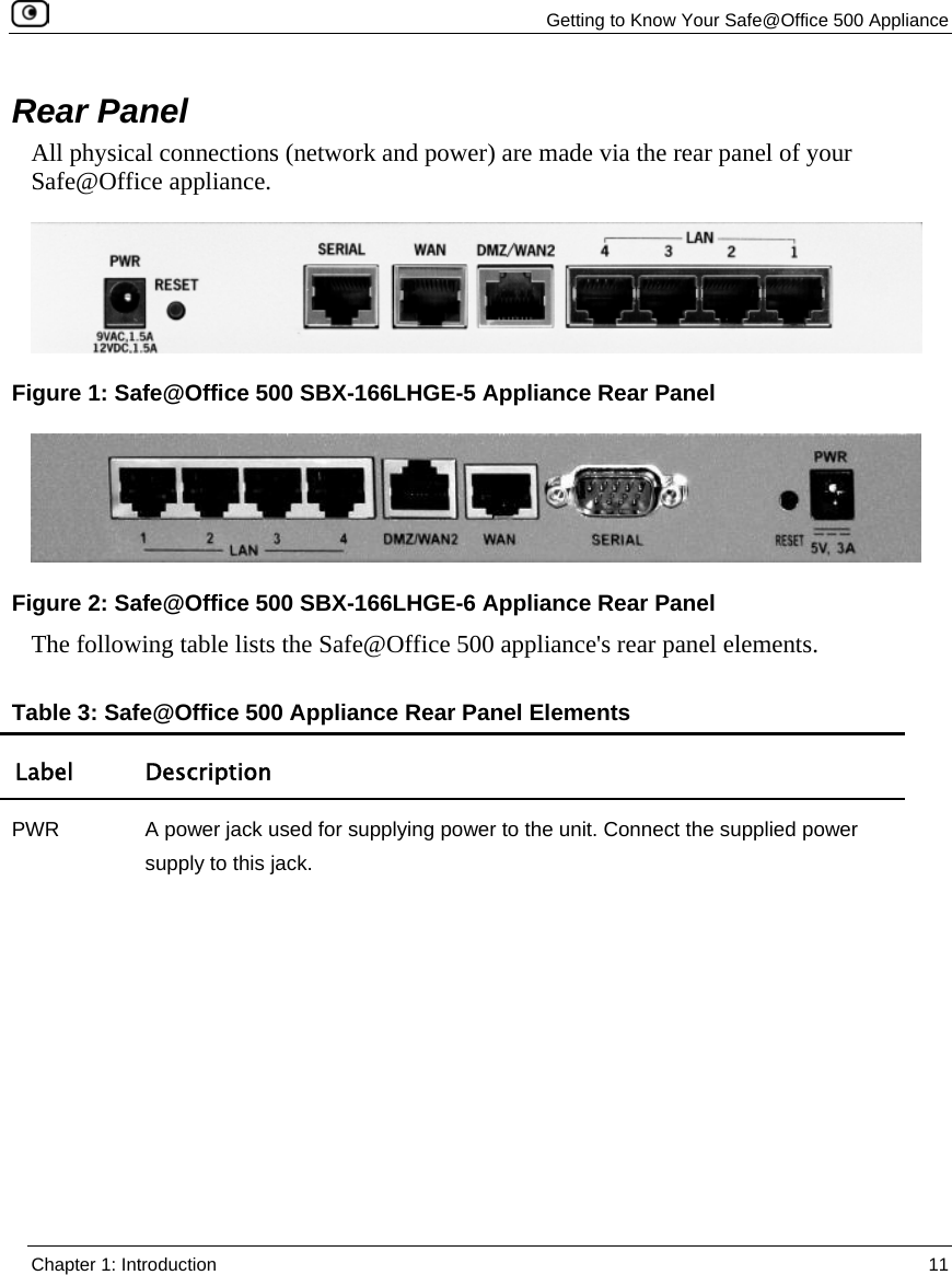
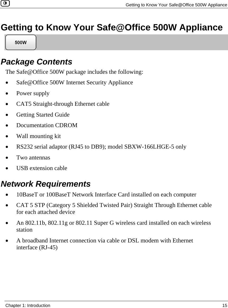
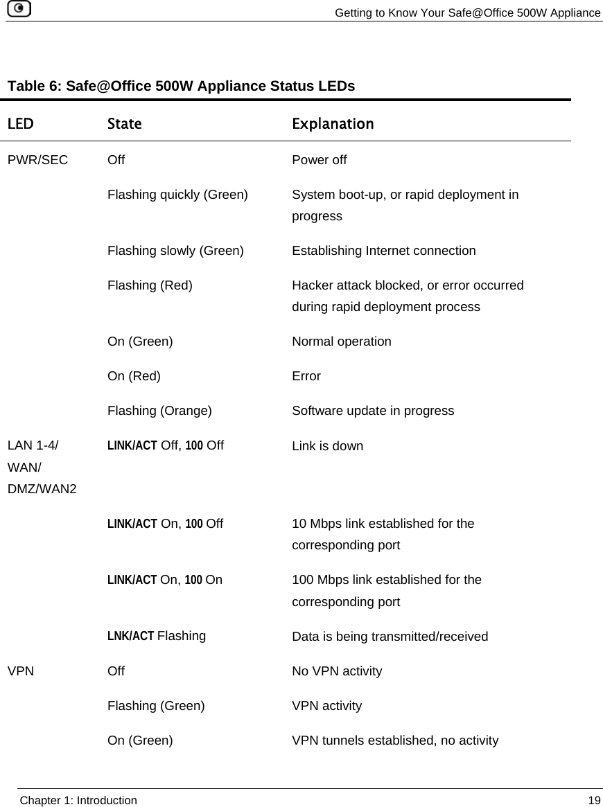


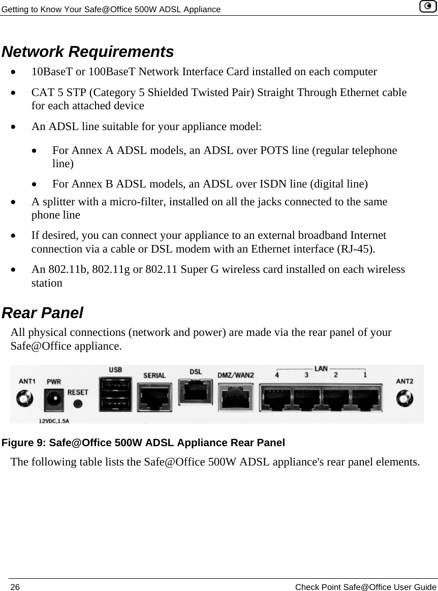

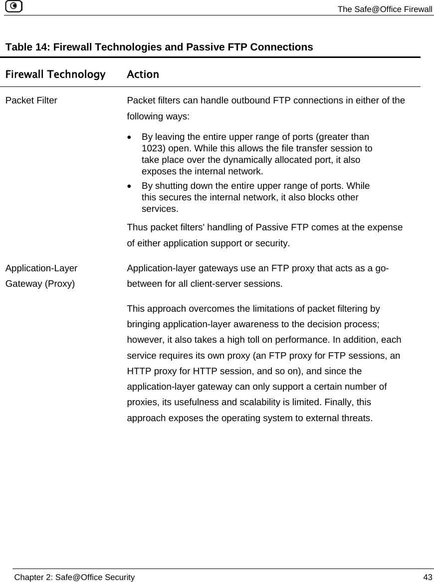
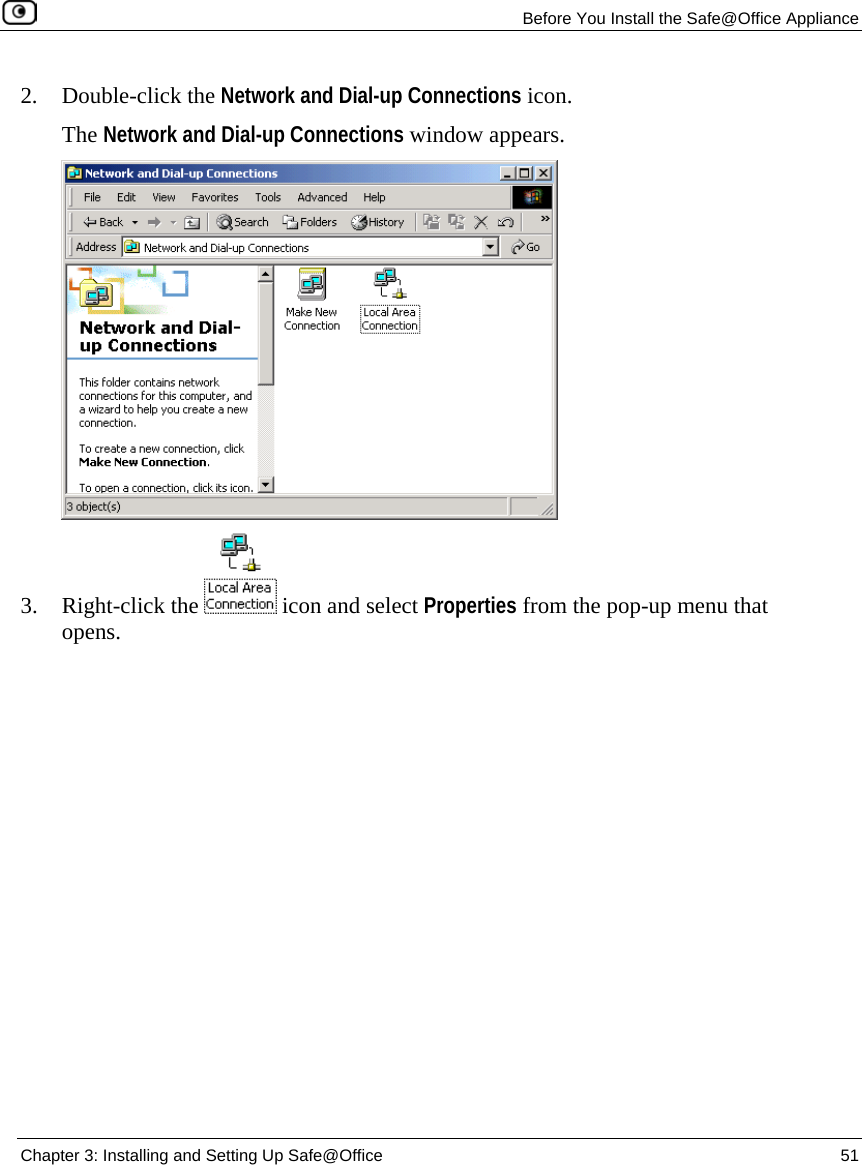


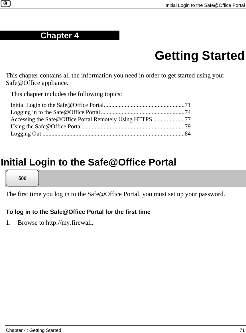
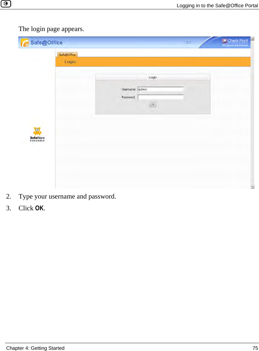
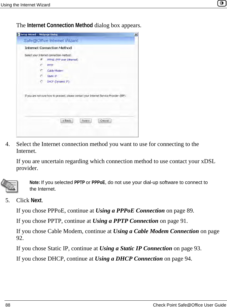
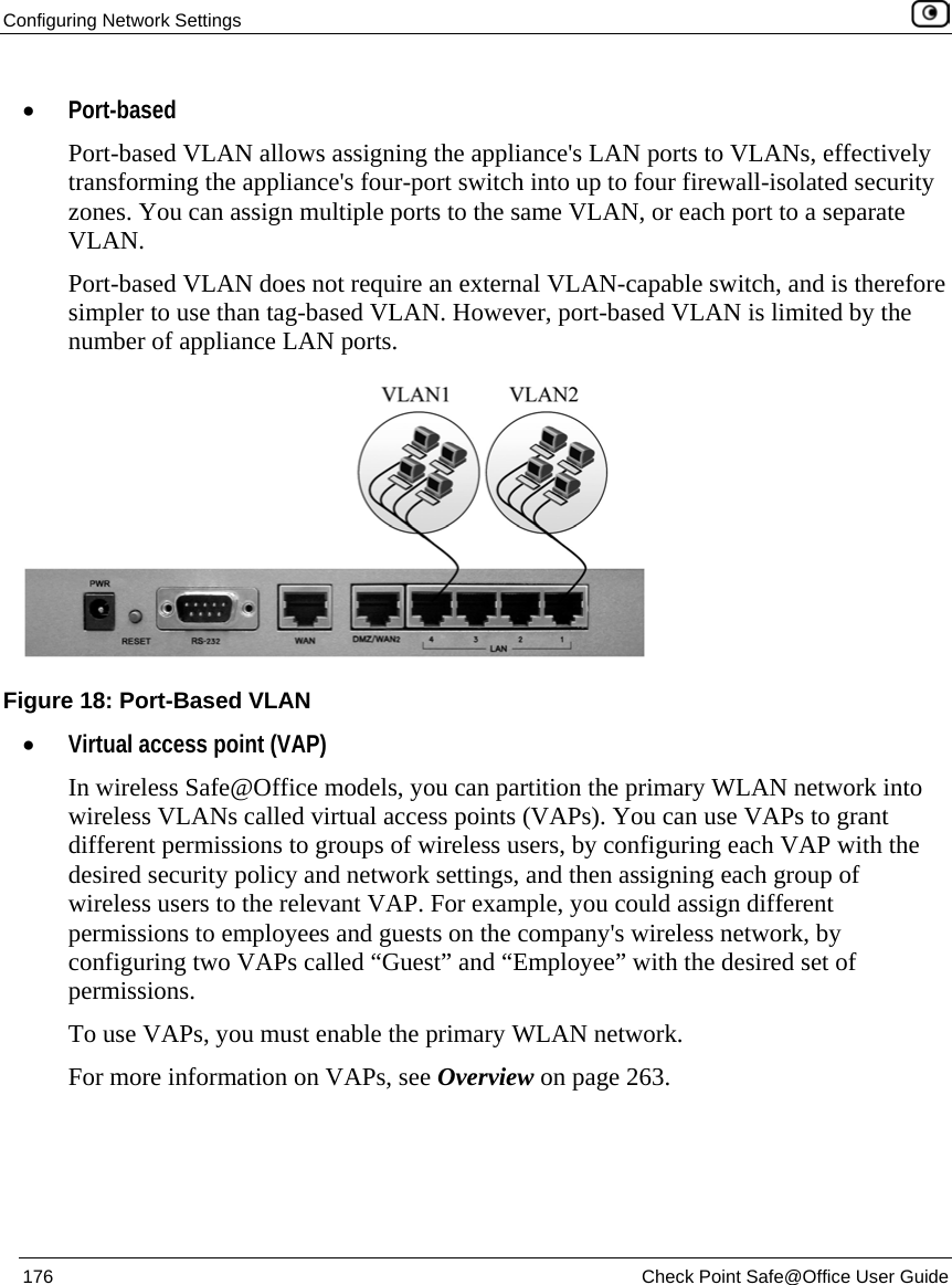
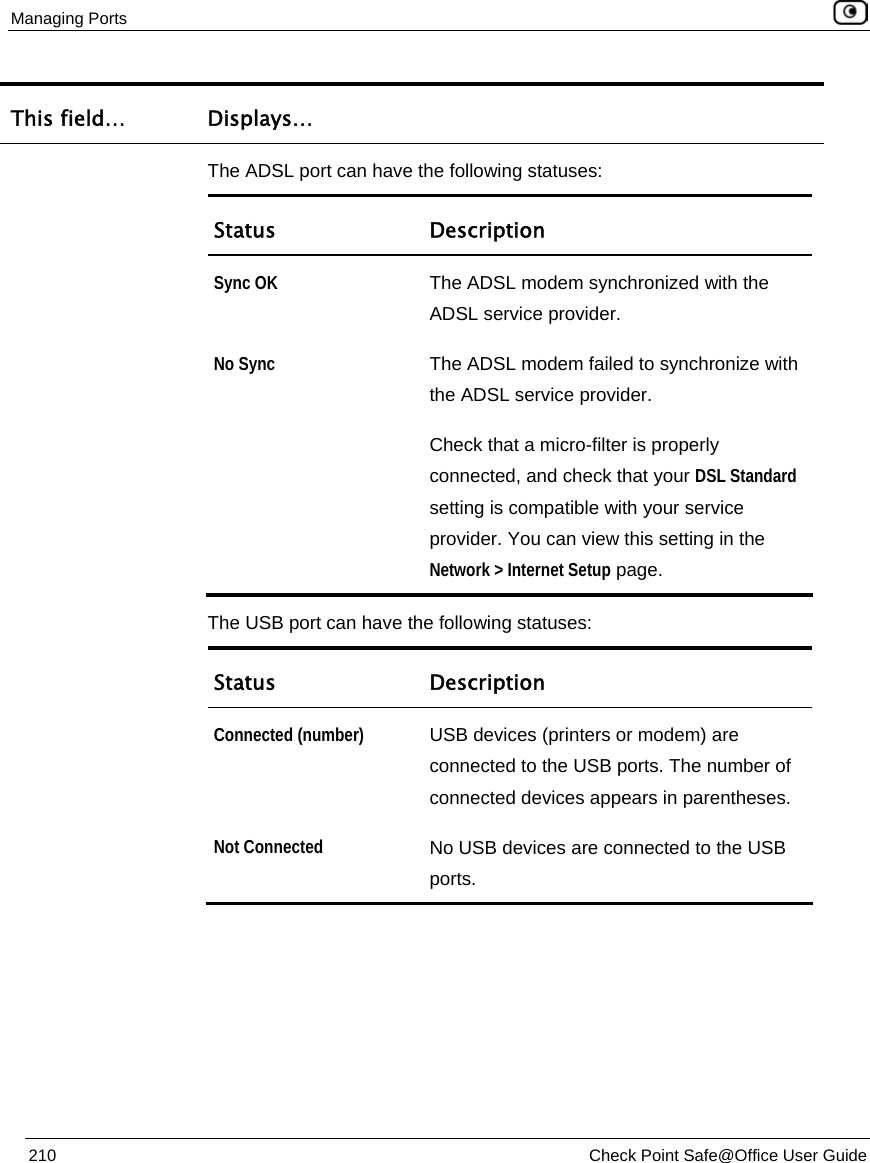
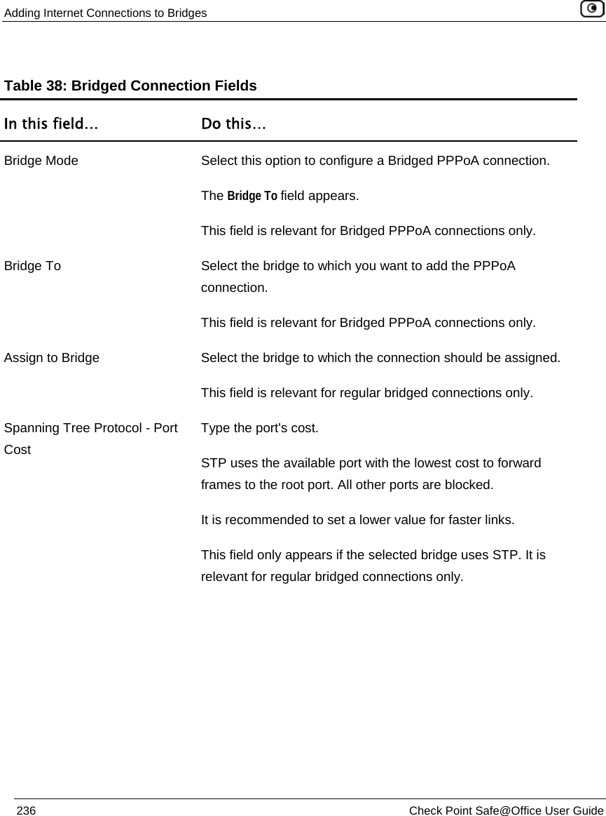
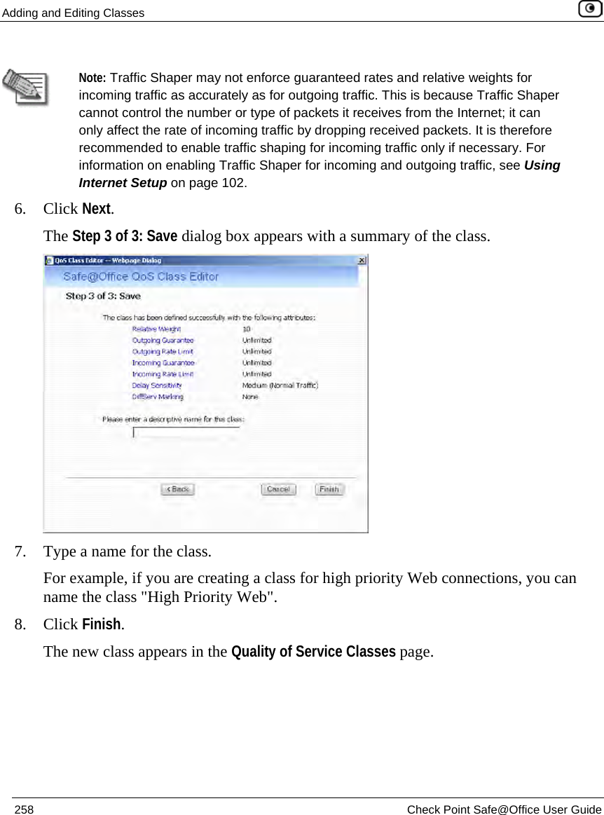
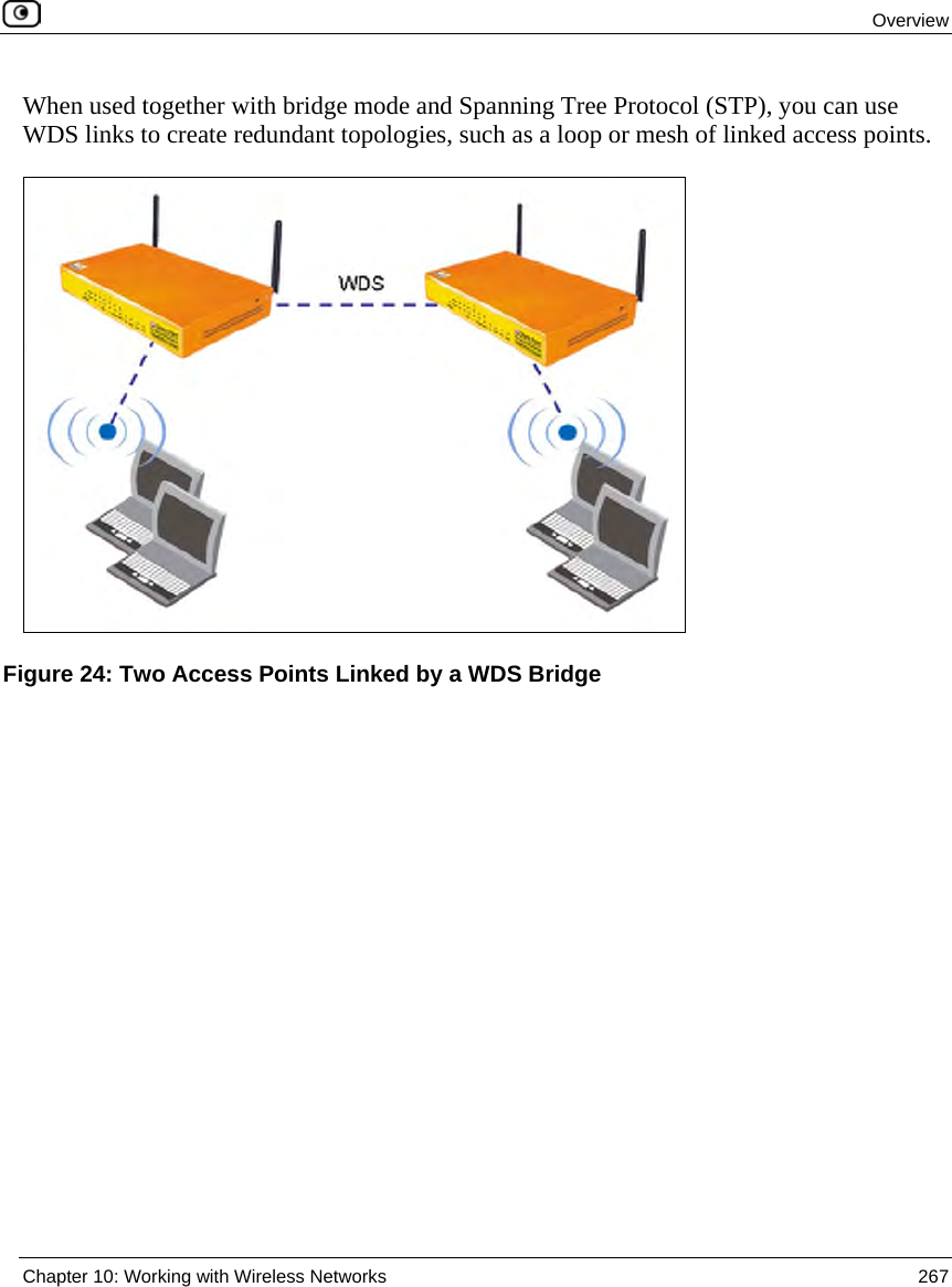
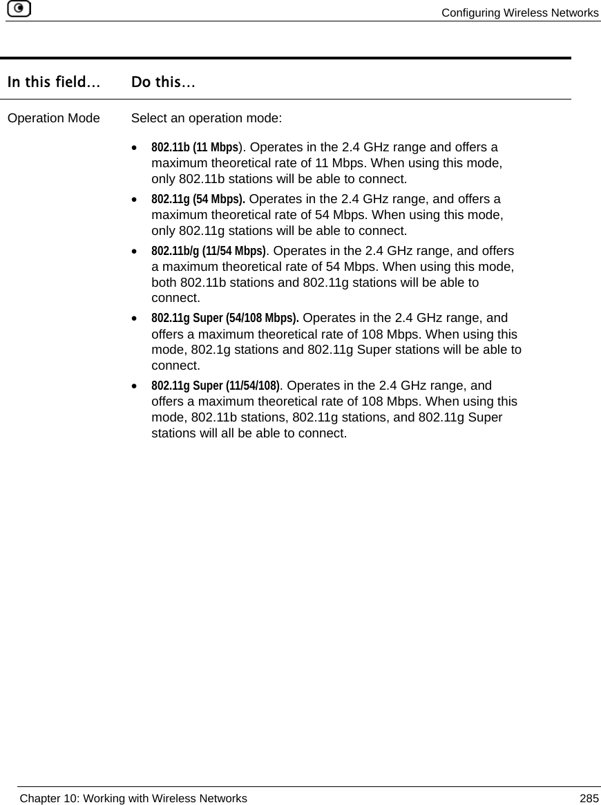
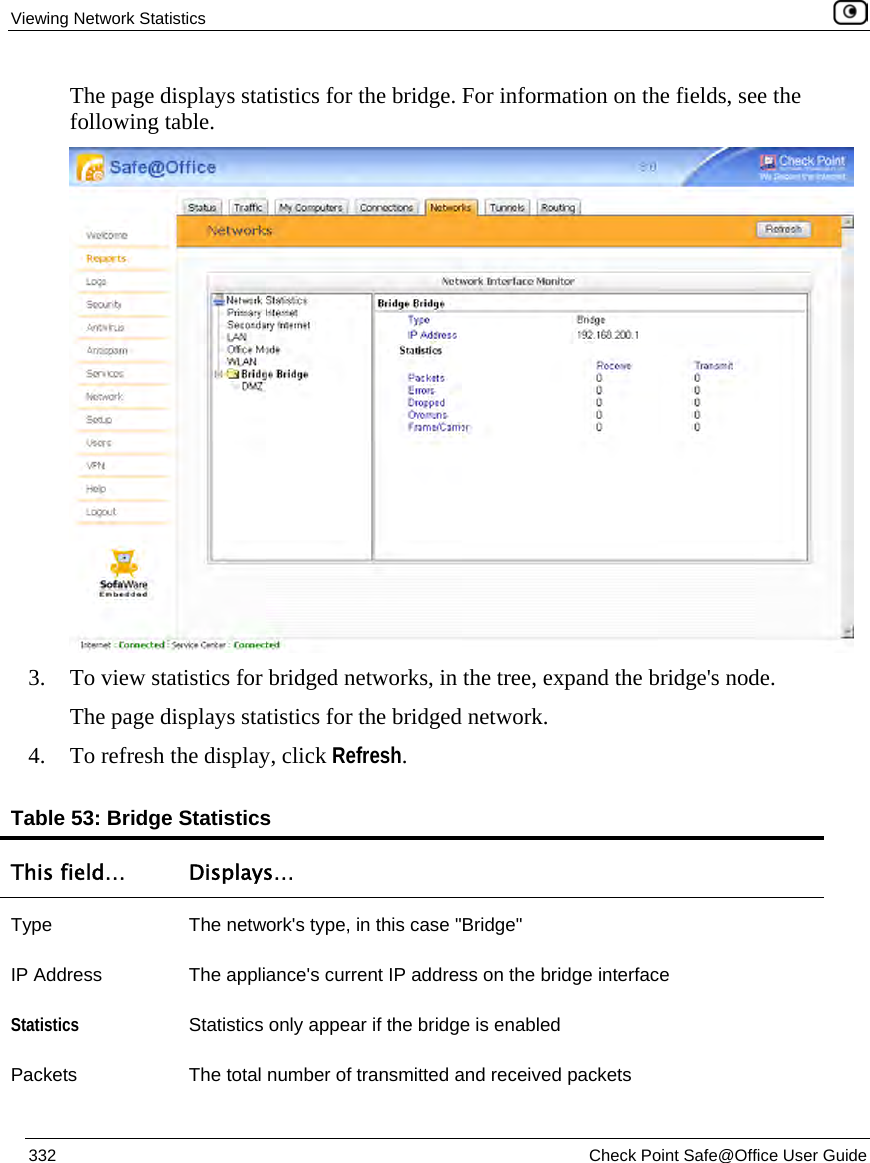
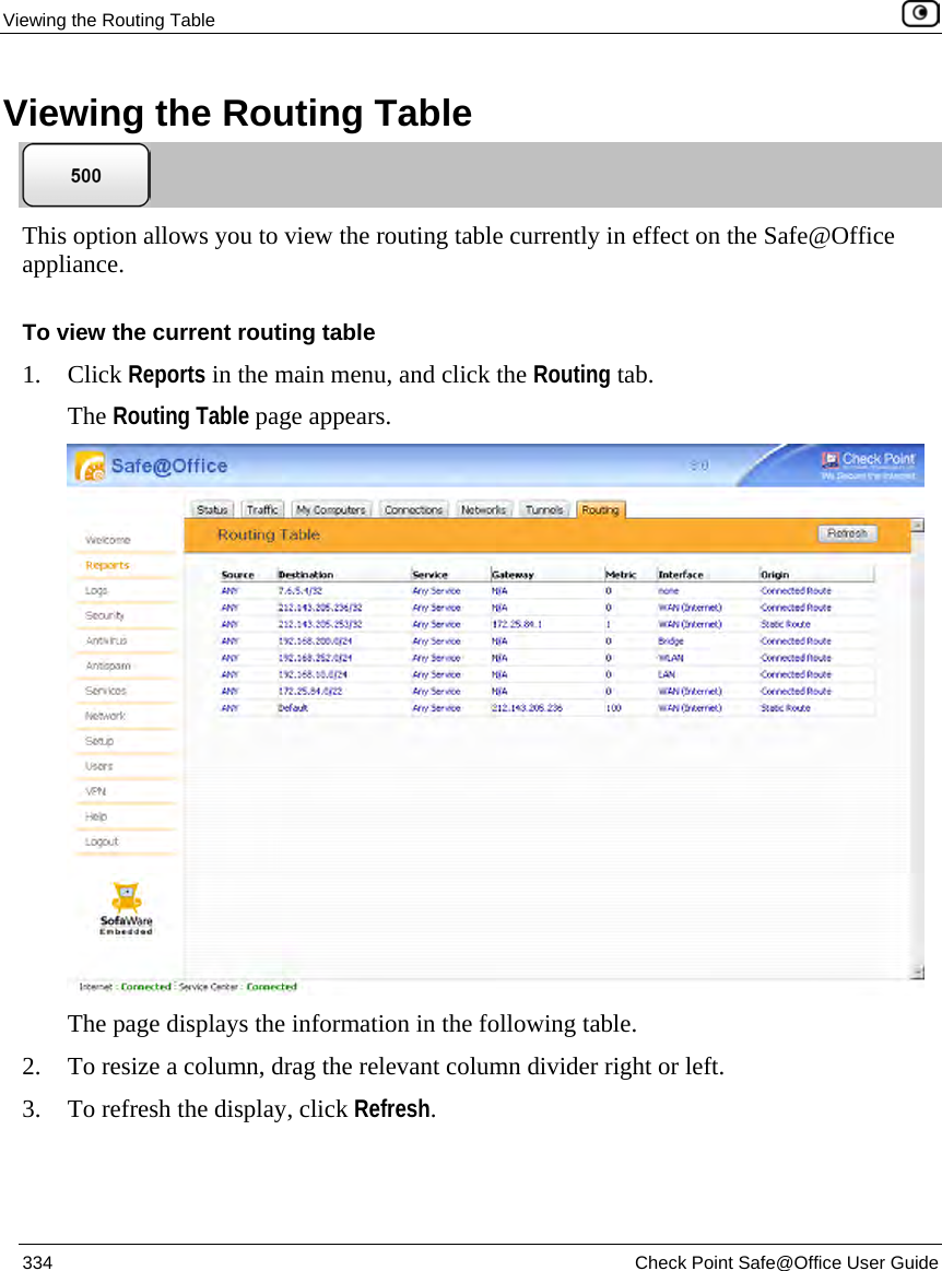
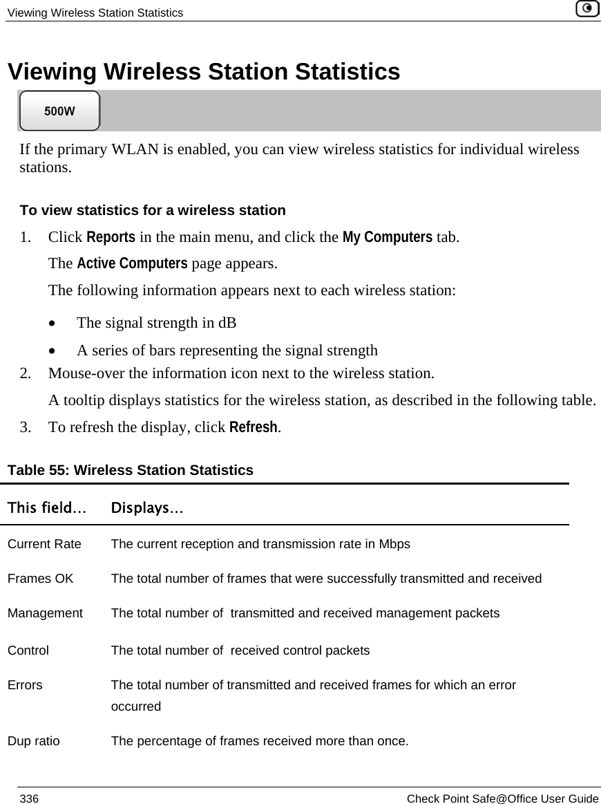
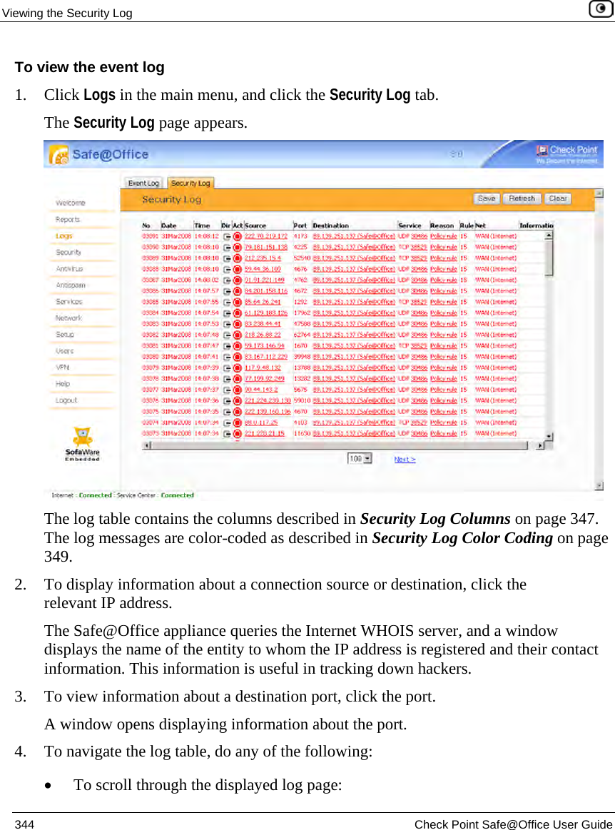
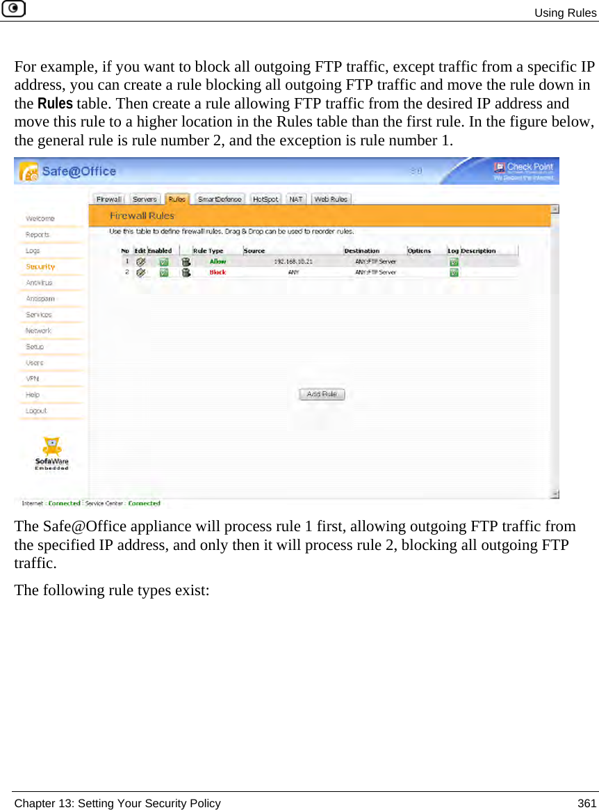
![Using the Safe@Office Portal 82 Check Point Safe@Office User Guide Status Bar The status bar is located at the bottom of each page. It displays the fields below, as well as the date and time. Table 17: Status Bar Fields This field… Displays this… Internet Your Internet connection status. The connection status may be one of the following: • Connected. The Safe@Office appliance is connected to the Internet. • Connected – Probing OK. Connection probing is enabled and has detected that the Internet connectivity is OK. • Connected – Probing Failed. Connection probing is enabled and has detected problems with the Internet connectivity. • Not Connected. The Internet connection is down. • Establishing Connection. The Safe@Office appliance is connecting to the Internet. • Contacting Gateway. The Safe@Office appliance is trying to contact the Internet default gateway. • Disabled. The Internet connection has been manually disabled. Note: You can configure both a primary and a secondary Internet connection. When both connections are configured, the Status bar displays both statuses. For example “Internet [Primary]: Connected”. For information on configuring a secondary Internet connection, see Configuring the Internet Connection on page 85.](https://usermanual.wiki/SofaWare-Technologies/SBX-11GWLAN-7.manual-part-1/User-Guide-1184423-Page-98.png)


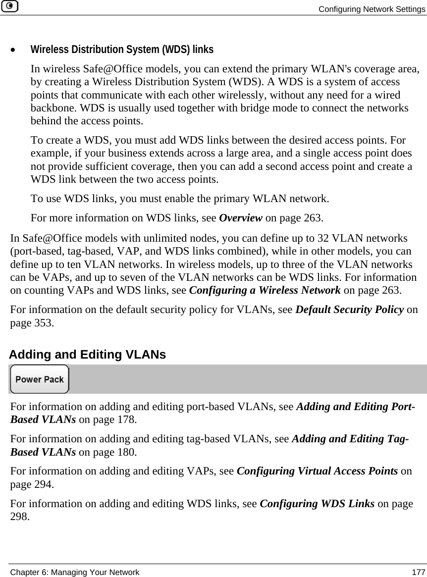


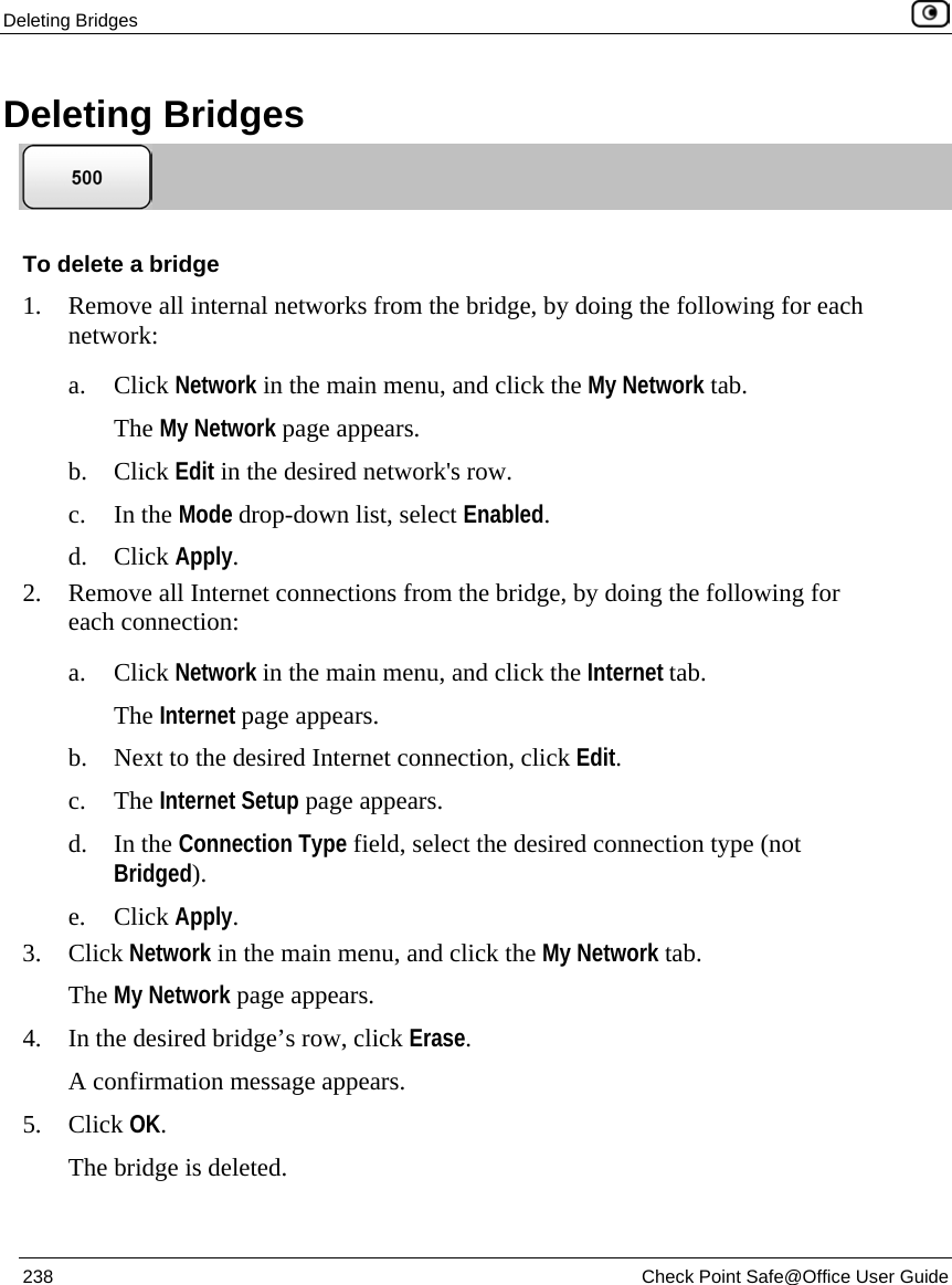


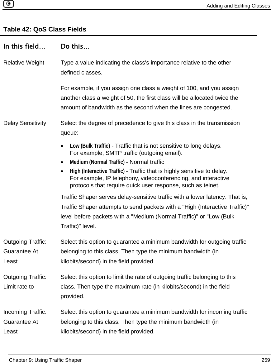
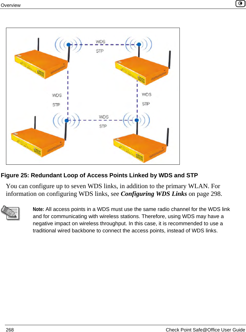


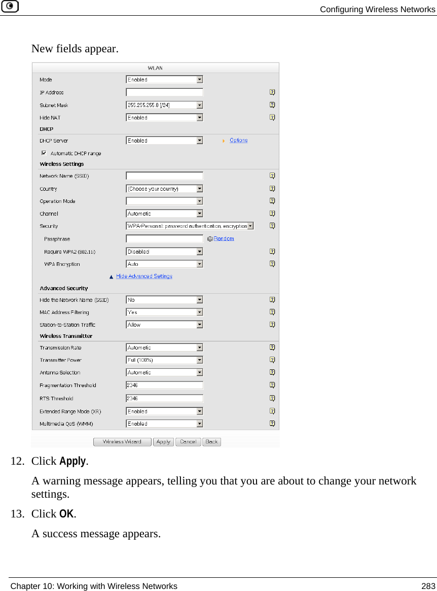
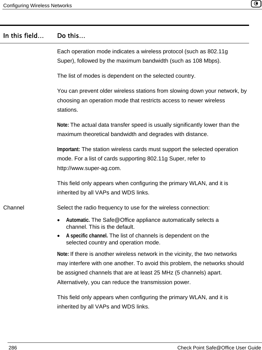


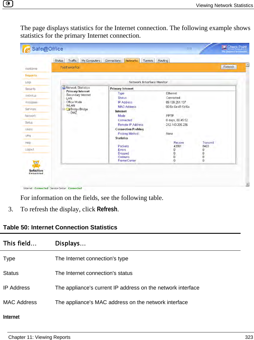
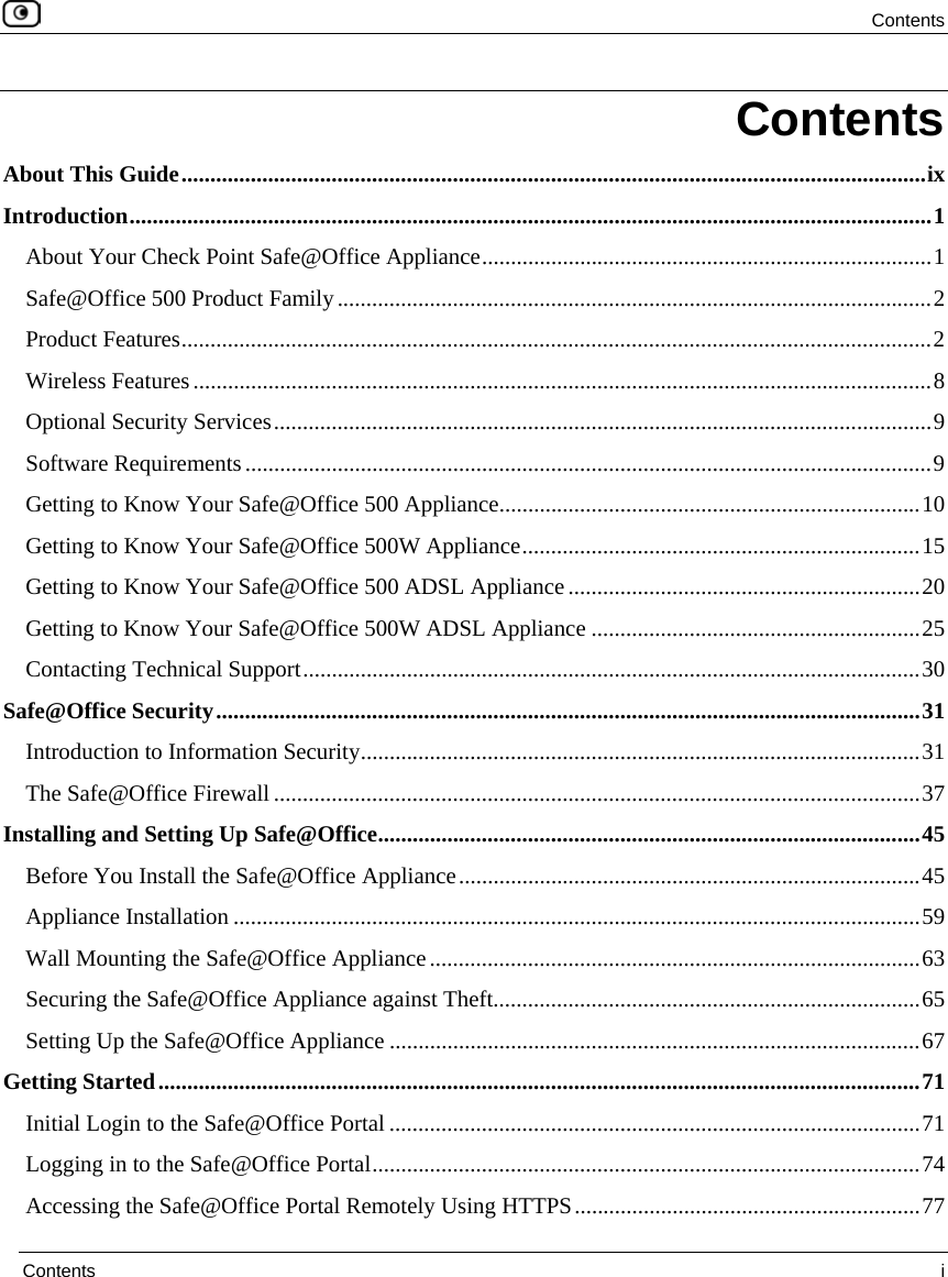
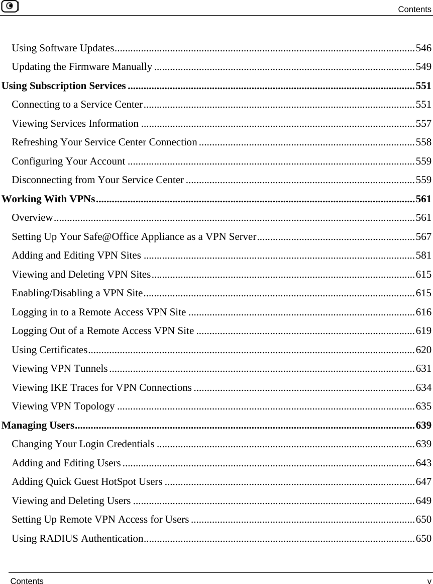
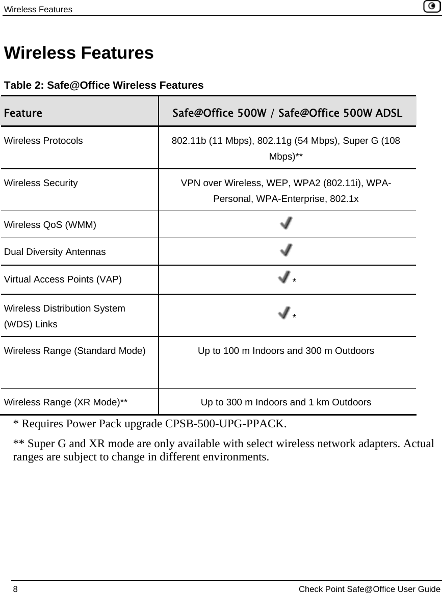
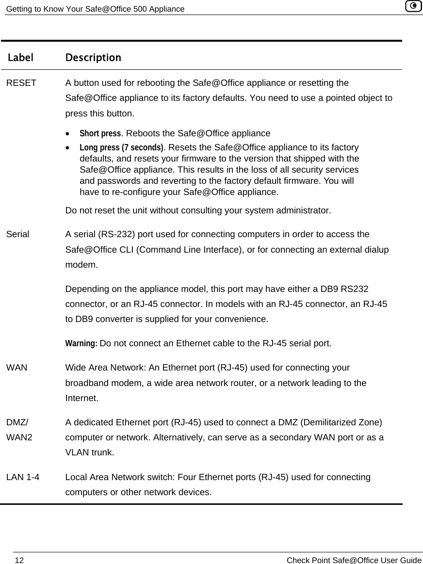
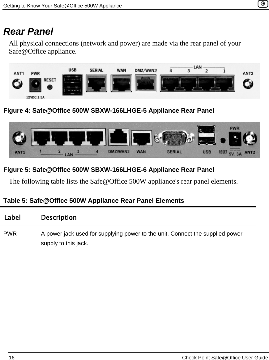
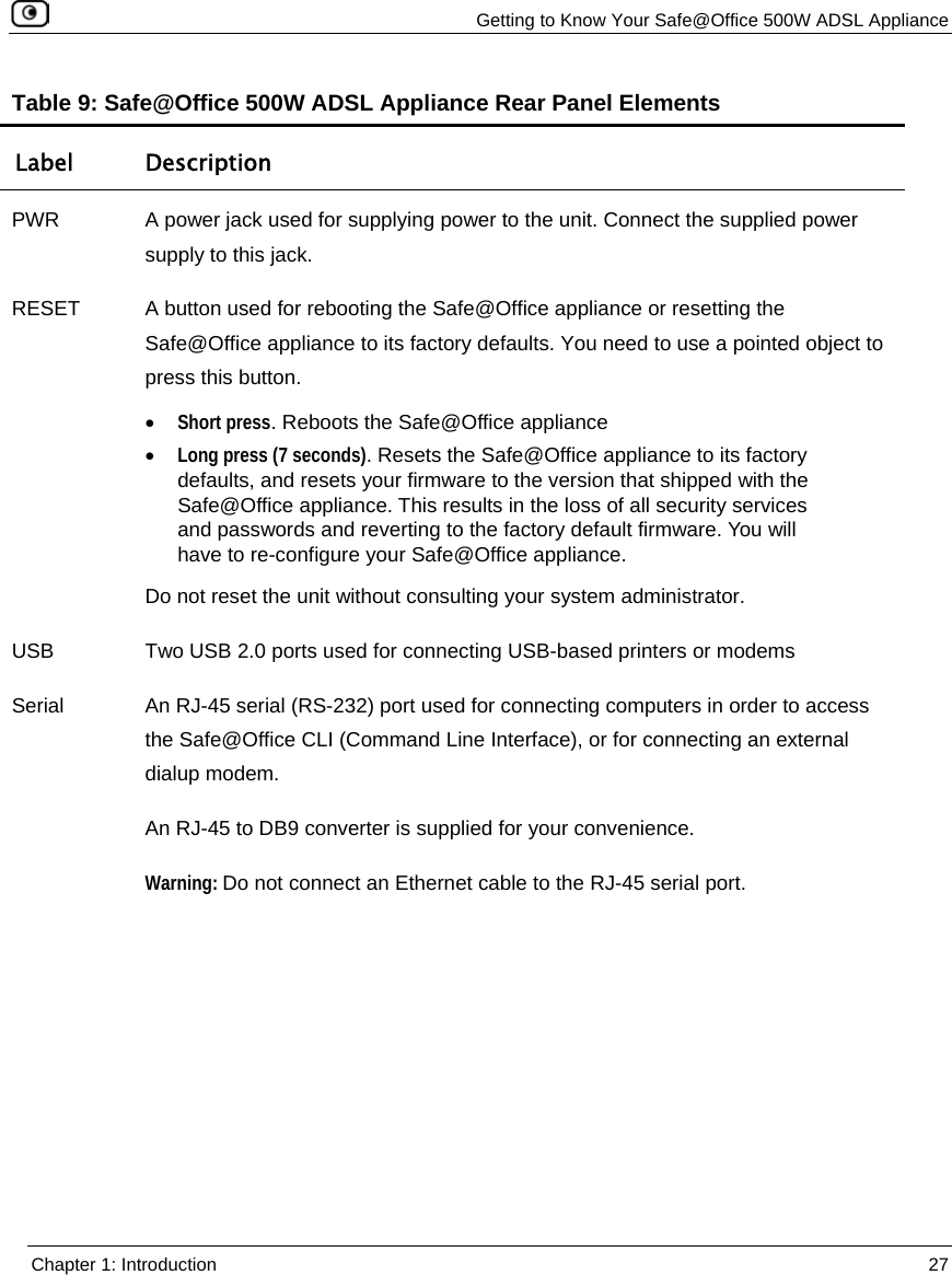
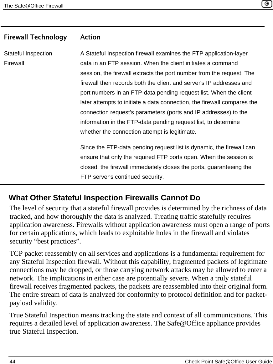
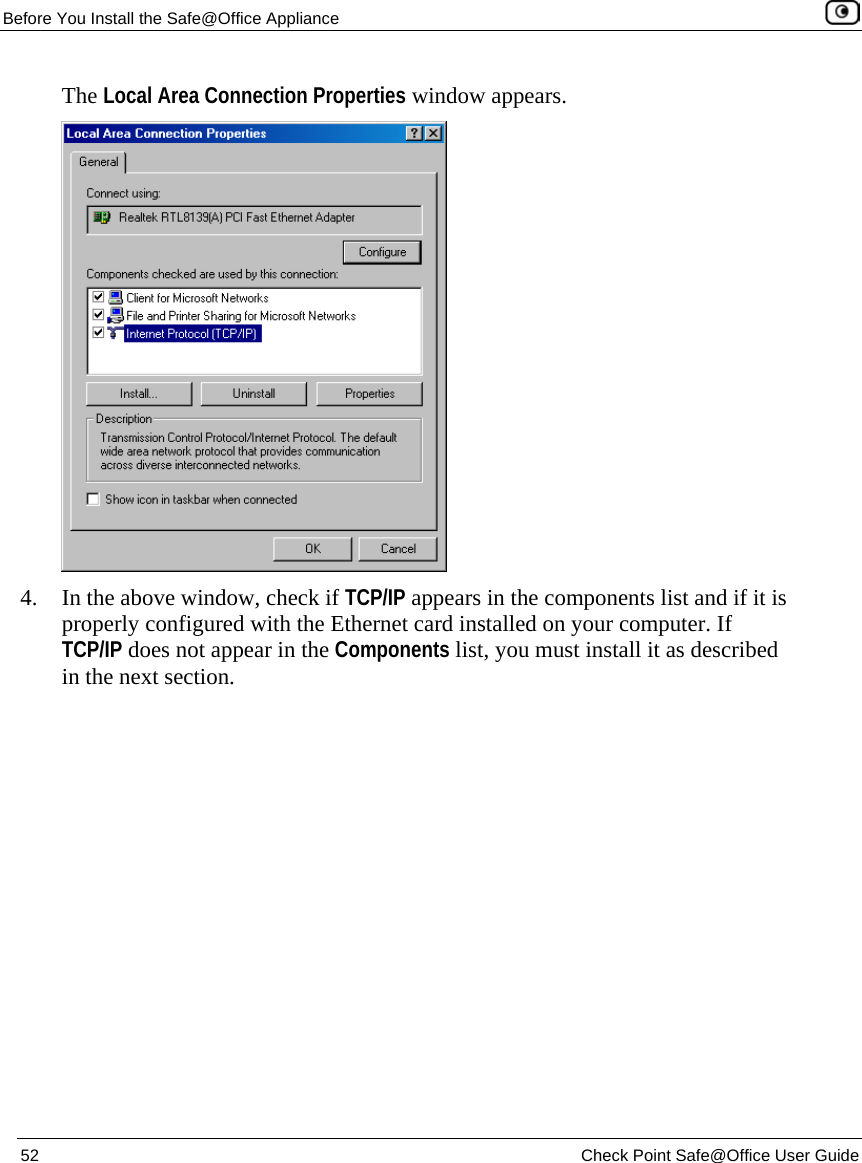
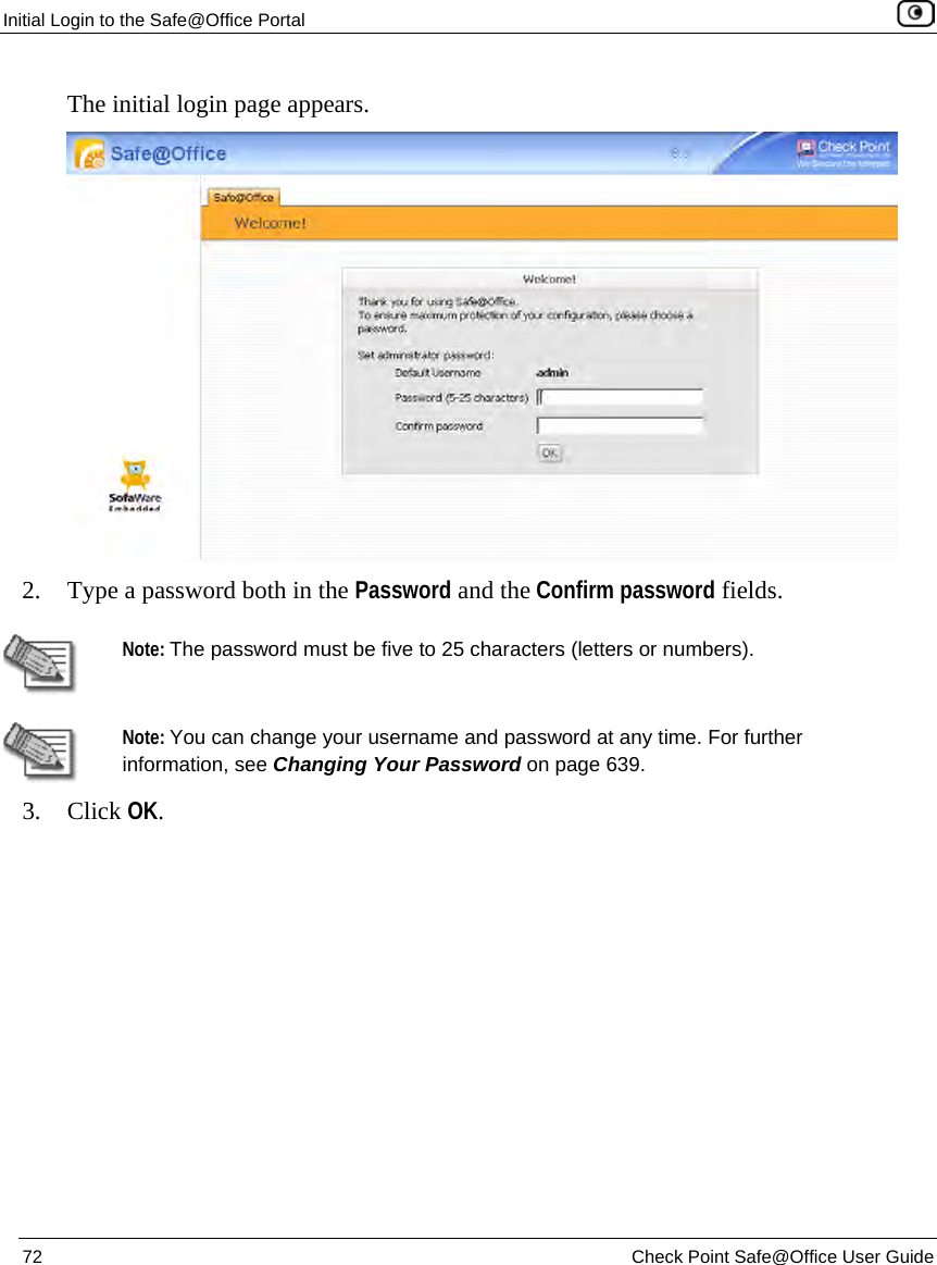
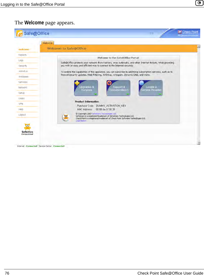
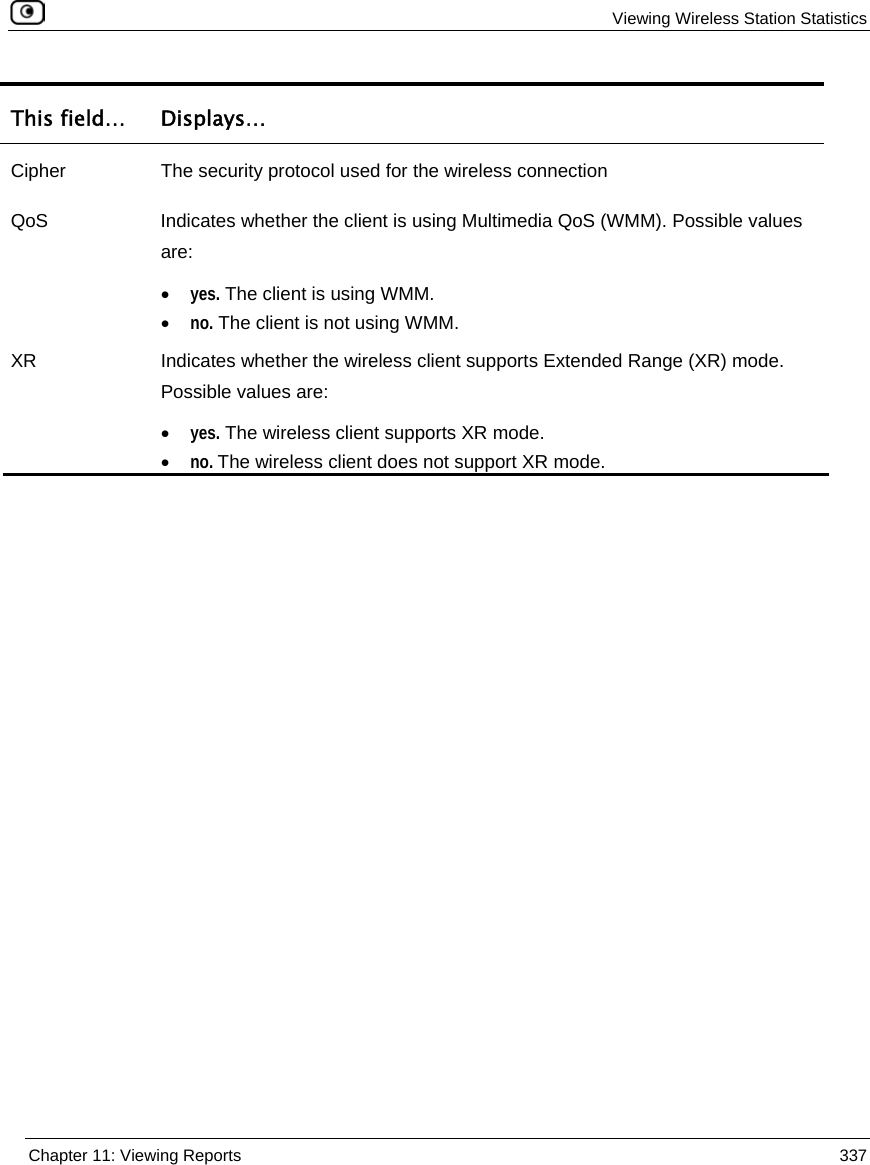
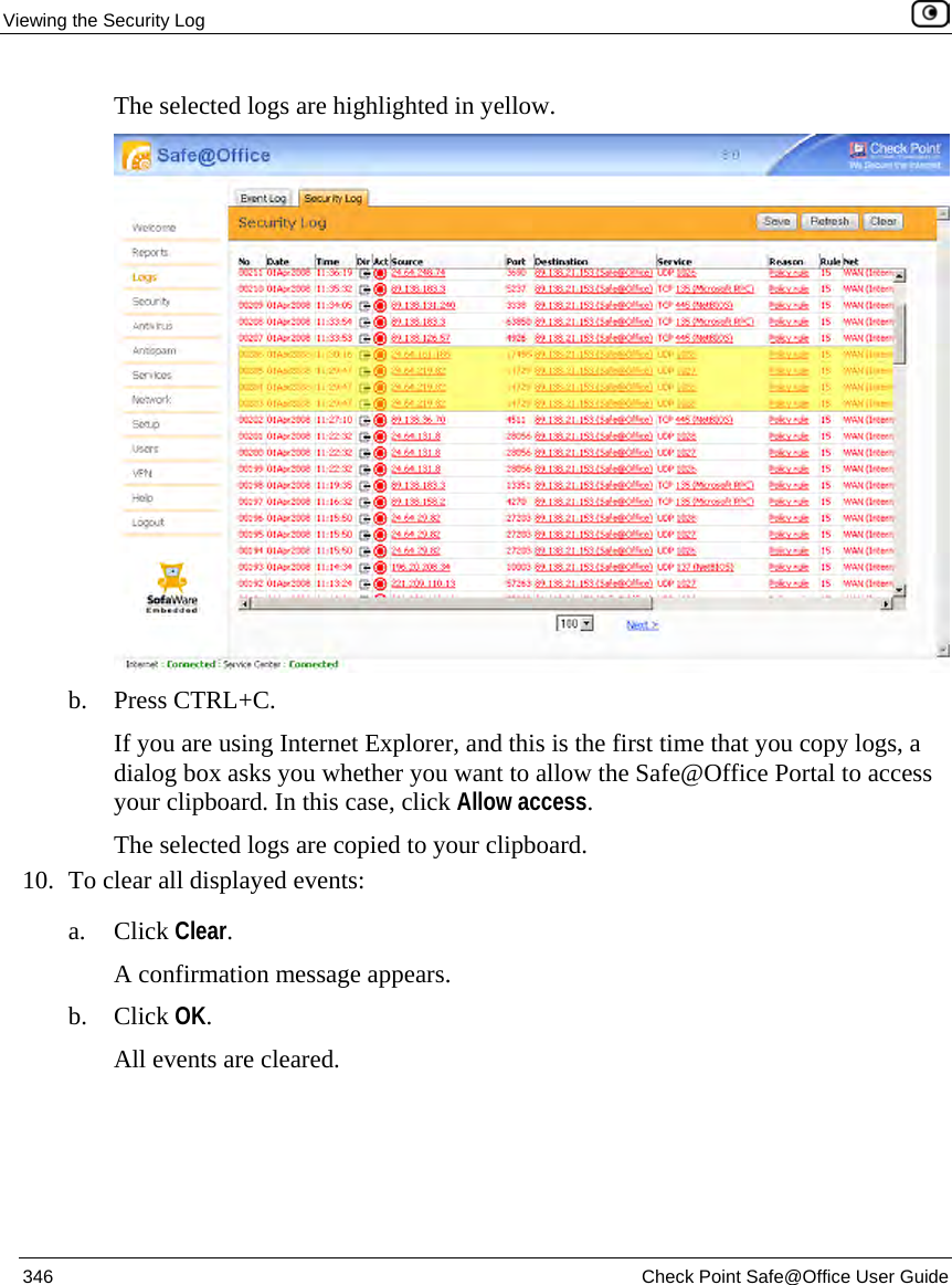
![Viewing Network Statistics 324 Check Point Safe@Office User Guide This field… Displays… Mode The Internet connection method used Connected The connection duration, in the format hh:mm:ss, where: hh=hours mm=minutes ss=seconds Remote IP Address The IP address of the PPP peer. This field is only relevant for PPP-based Internet connections. Connection Probing Probing Method The connection probing method configured for the Internet connection ADSL These fields only appear for ADSL connections. Standard The DSL line's standard Annex The Safe@Office ADSL model (Annex A, Annex B) Self Test Indicates whether DSL modem has passed a self-test Trellis Coding The DSL line's trellis coding Framing Structure The DSL line's framing structure Line Rate The line rate for transmission (TX) and reception (RX) in kbps ADSL Firmware The installed ADSL firmware ADSL Firmware [Backup] The installed backup ADSL firmware](https://usermanual.wiki/SofaWare-Technologies/SBX-11GWLAN-7.manual-part-1/User-Guide-1184423-Page-340.png)
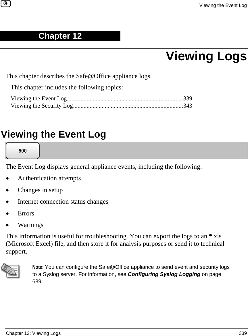


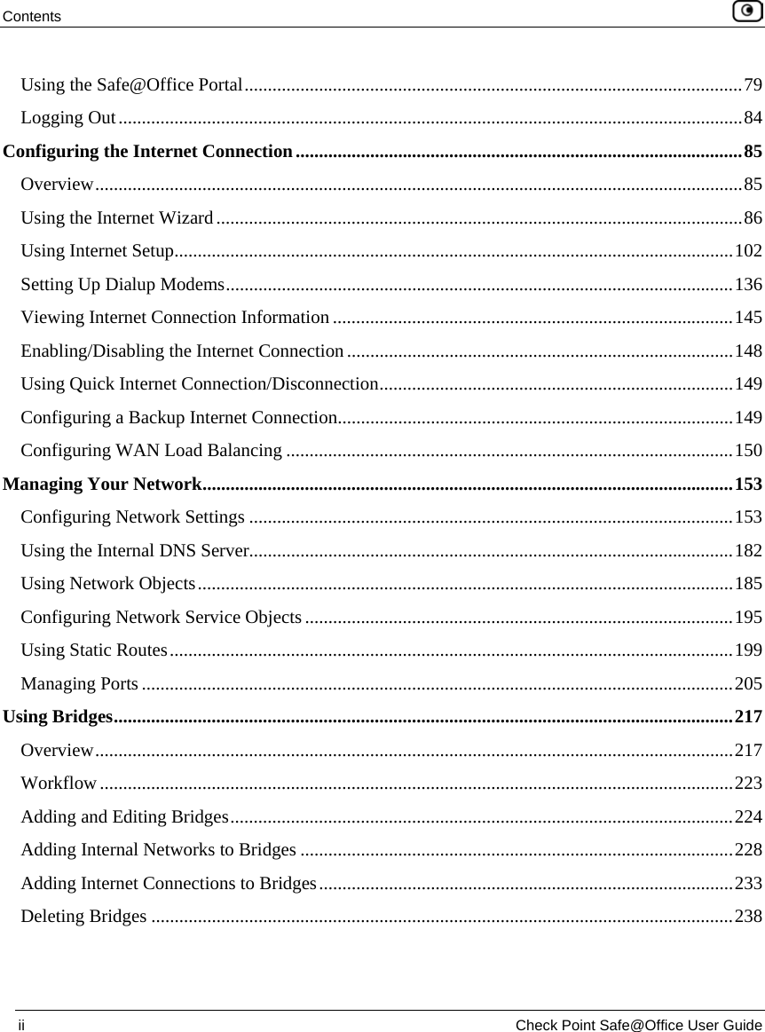
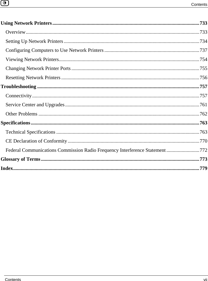
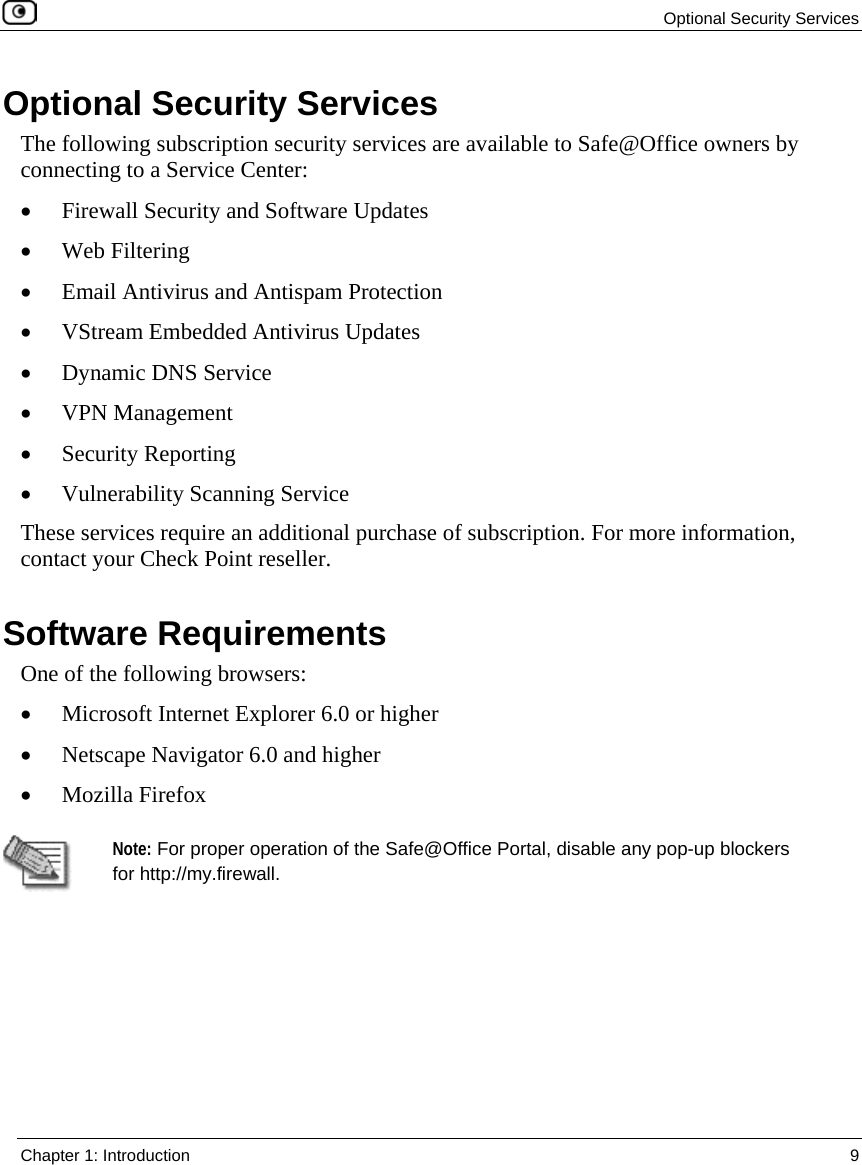
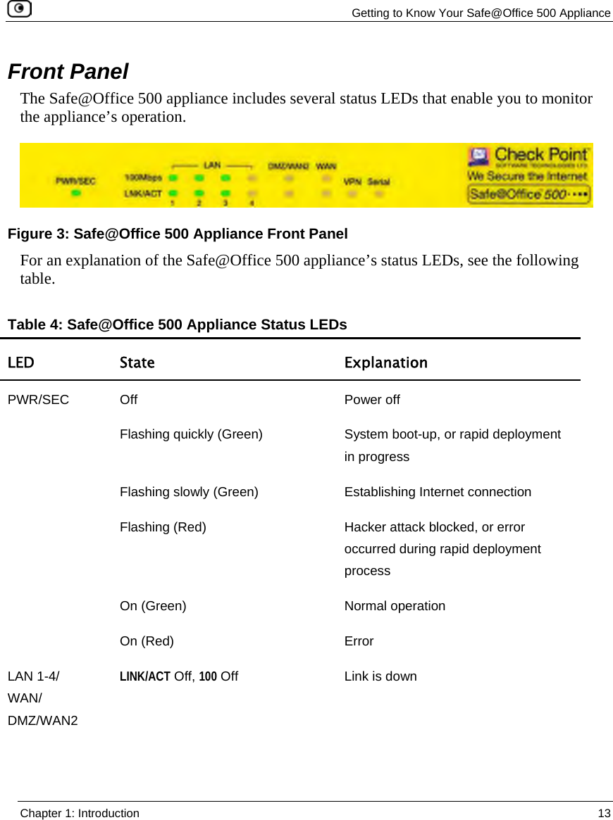
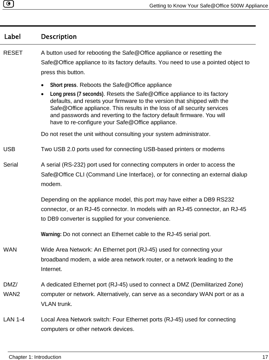
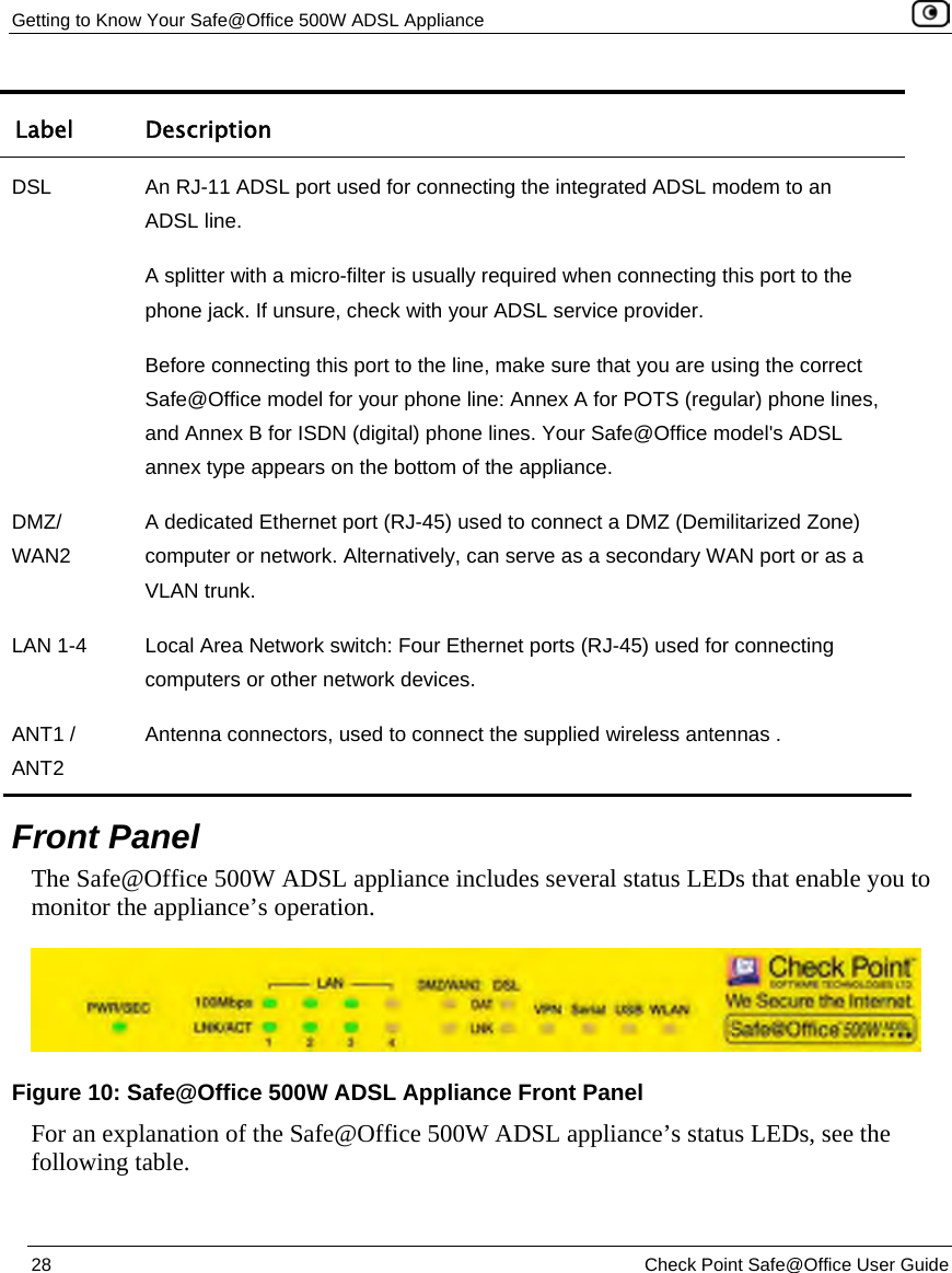
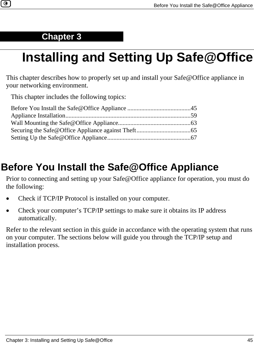
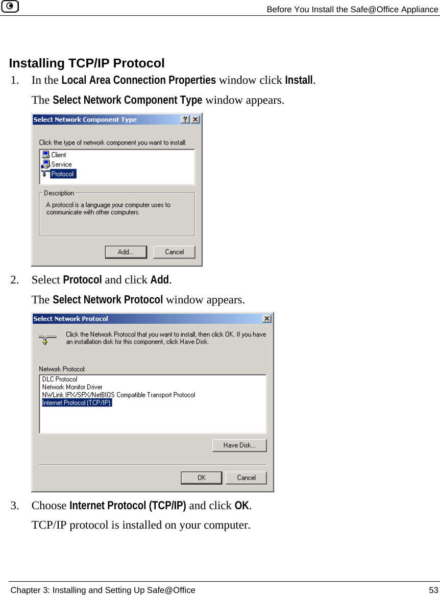
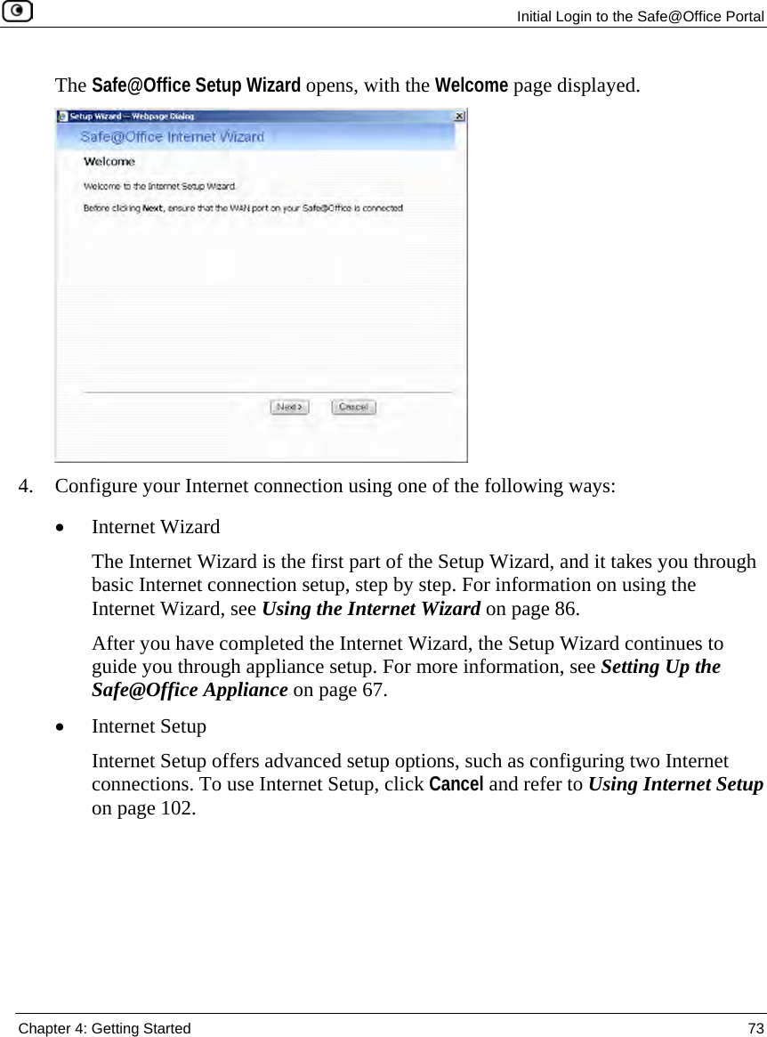
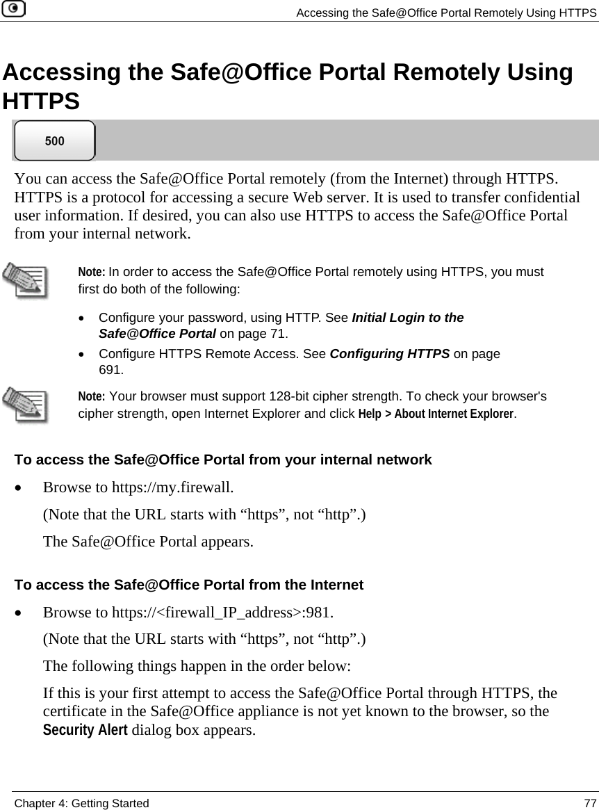
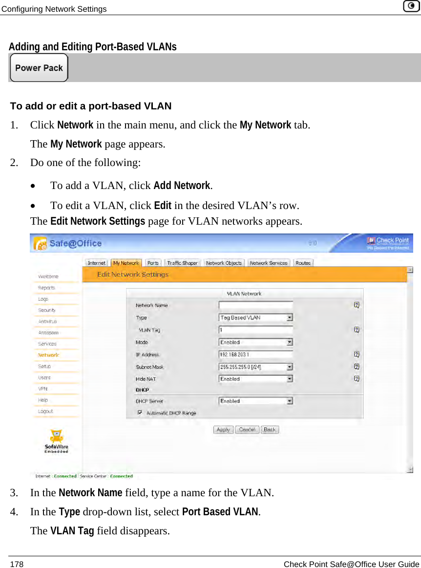
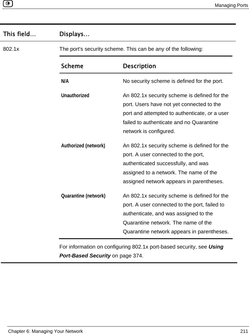
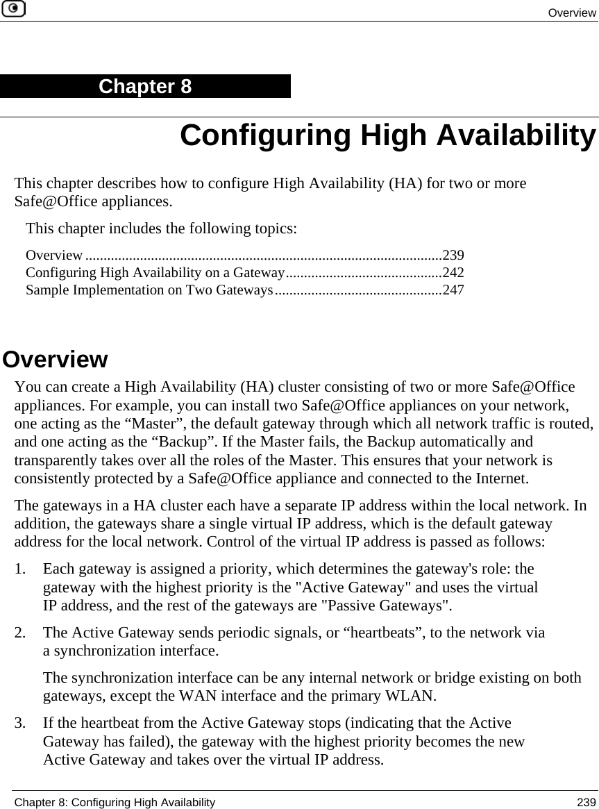
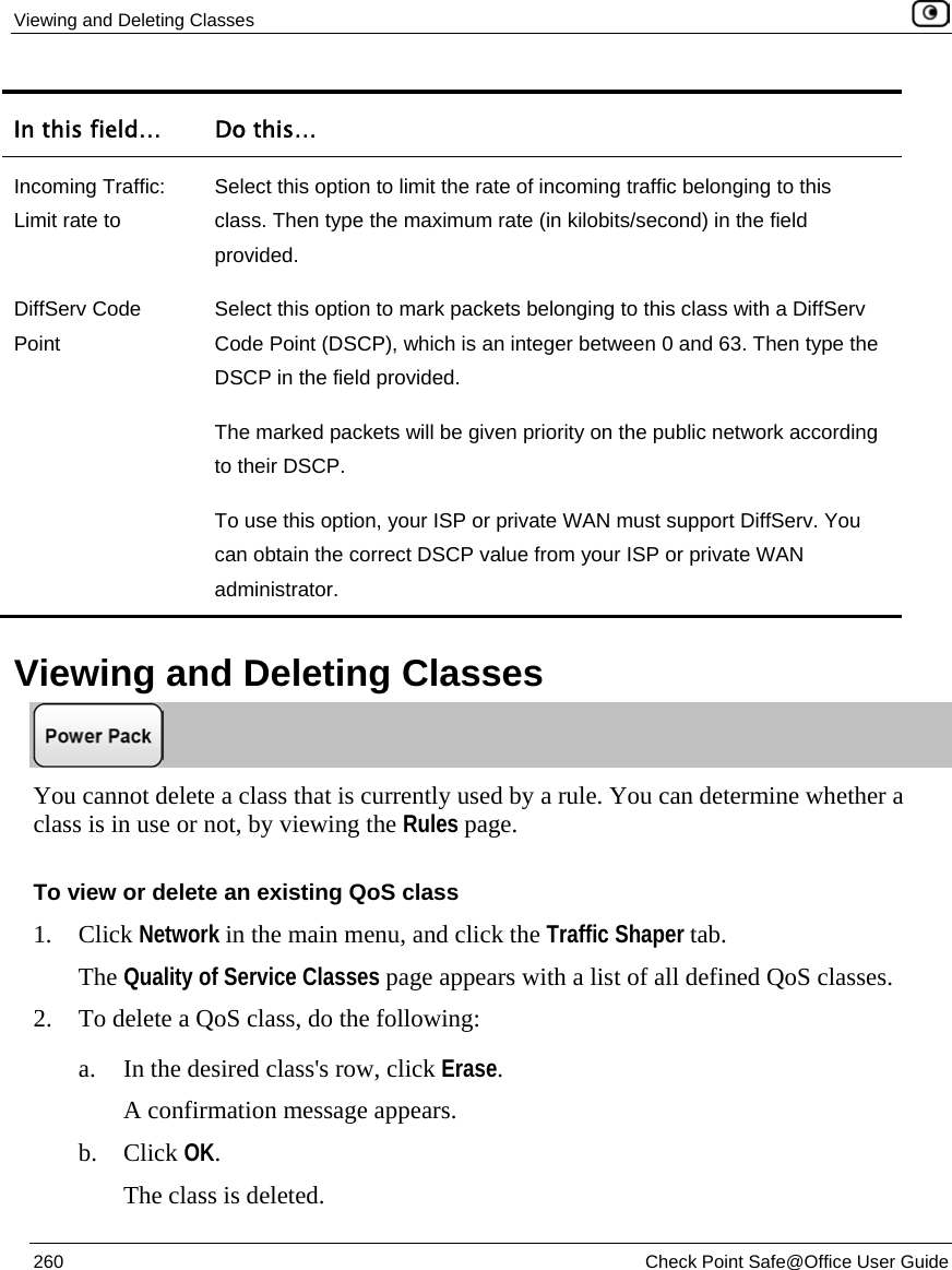
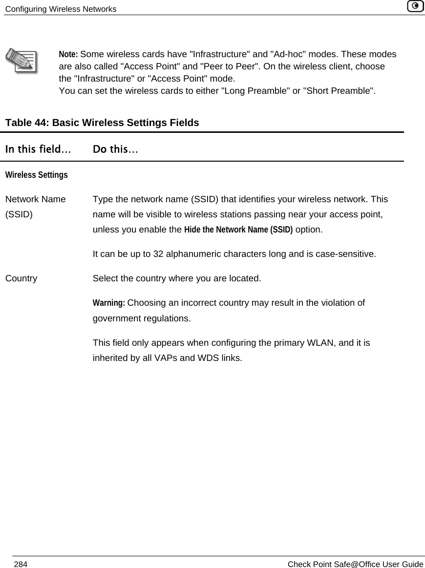
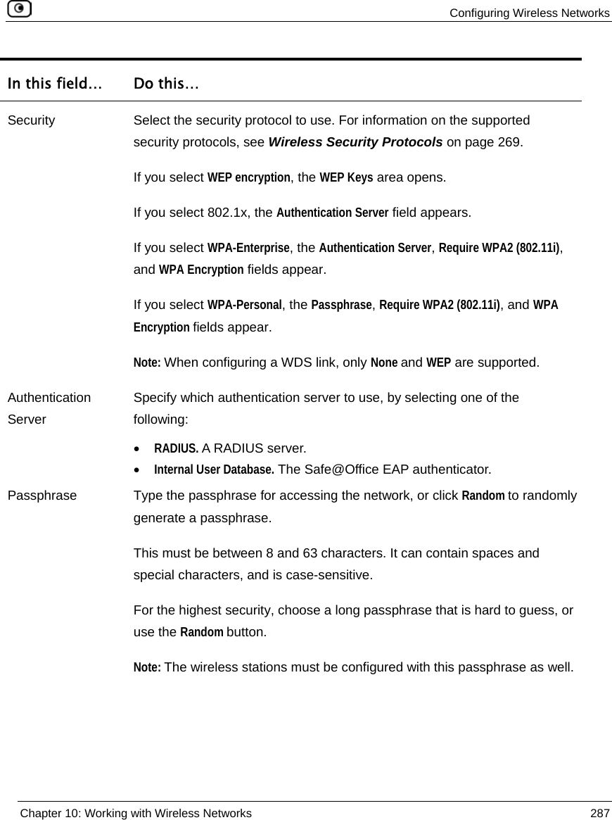
![Using Port-Based Security 374 Check Point Safe@Office User Guide The rule is deleted. Using Port-Based Security The Safe@Office appliance supports the IEEE 802.1x standard for secure authentication of users and devices that are directly attached to Safe@Office appliance's LAN and DMZ ports, as well as the wireless LAN. Authentication can be performed either by an external RADIUS server, or by the Safe@Office appliance's built-in EAP authenticator. For information on the Safe@Office EAP authenticator, see Using the Safe@Office EAP Authenticator on page 394. When an 802.1x security scheme is implemented for a port, users attempting to connect to that port are required to authenticate using their network user name and password. The Safe@Office appliance sends the user's credentials to the configured authentication server, and if authentication succeeds, a connection is established. If the user fails to authenticate, the port is physically isolated from other ports on the gateway. If desired, you can specify how users should be handled after successful or failed authentication. Users who authenticate successfully on a specific port are assigned to the network with which that port is associated. For example, if the port is assigned to the DMZ network, all users who authenticate successfully on that port are assigned to the DMZ network. When using a RADIUS server for authentication, you can assign authenticated users to specific network segments, by configuring dynamic VLAN assignment on the RADIUS server. Upon successful authentication, the RADIUS server sends RADIUS option 81 [Tunnel-Private-Group-ID] to the Safe@Office appliance, indicating to which network segment the user should be assigned. For example, if a member of the Accounting team connects to a network port and attempts to log in, the Safe@Office appliance relays the information to the RADIUS server, which replies with RADIUS option 81 and the value “Accounting”. The appliance then assigns the user’s port to the Accounting network, granting the user access to all the resources of the Accounting team. The Safe@Office appliance also enables you to automatically assign users to a “Quarantine” network when authentication fails. All Quarantine network security and network rules will apply to those users. For example, you can create security rules allowing users on the Quarantine network to access the Internet and blocking them from](https://usermanual.wiki/SofaWare-Technologies/SBX-11GWLAN-7.manual-part-1/User-Guide-1184423-Page-390.png)
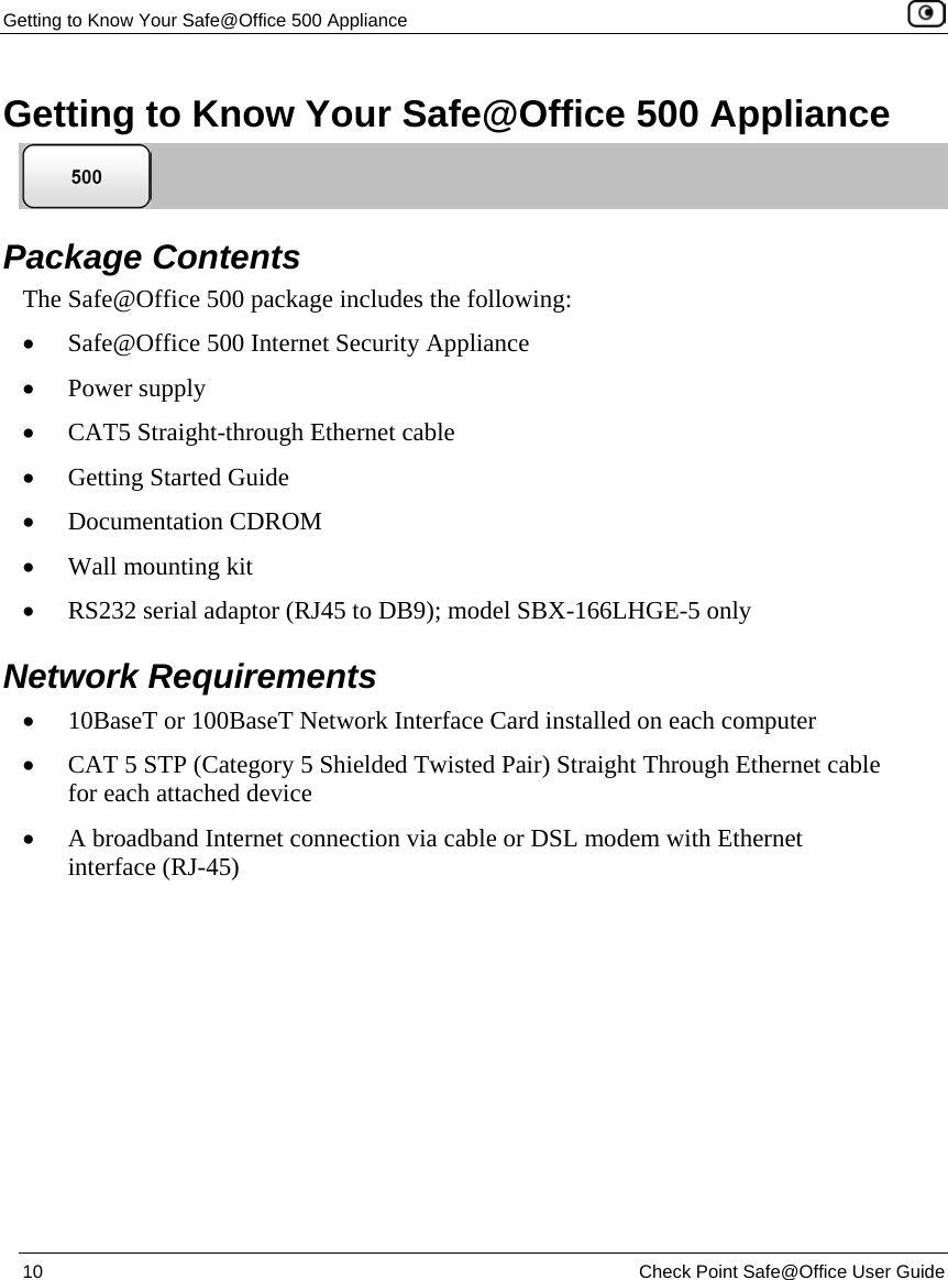
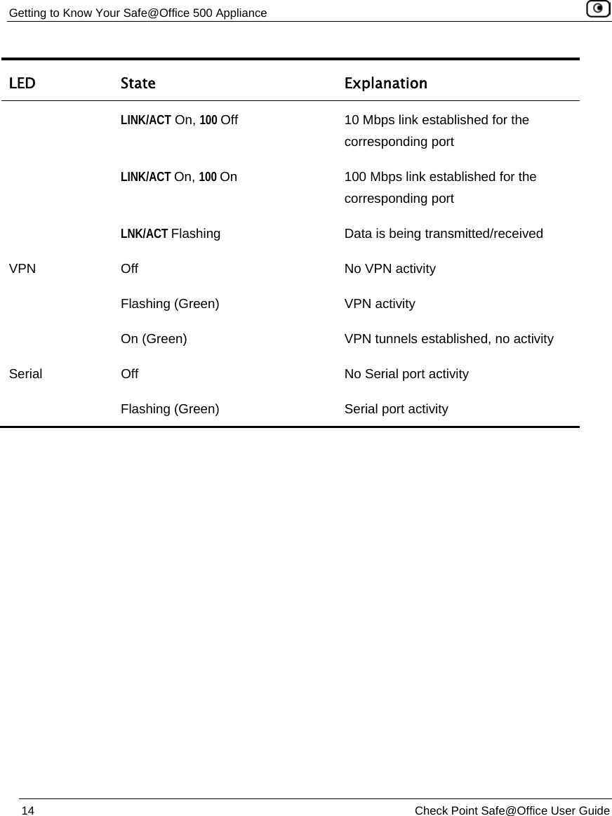
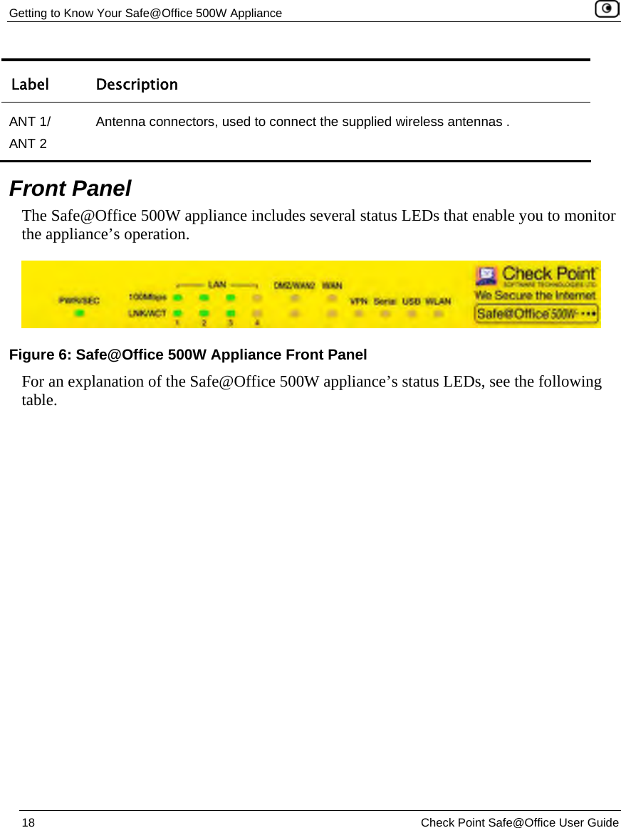
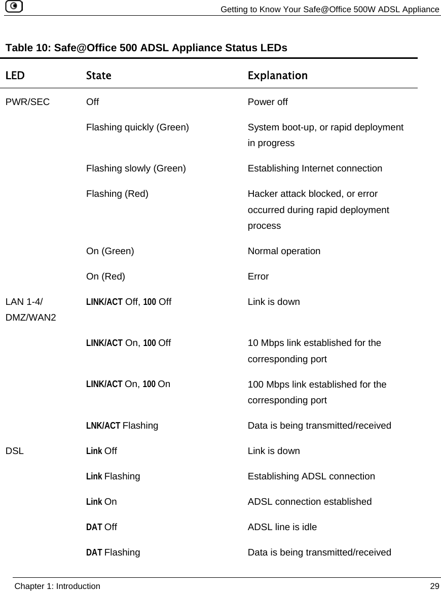
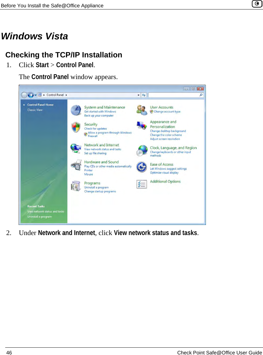
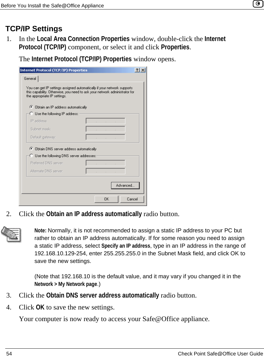
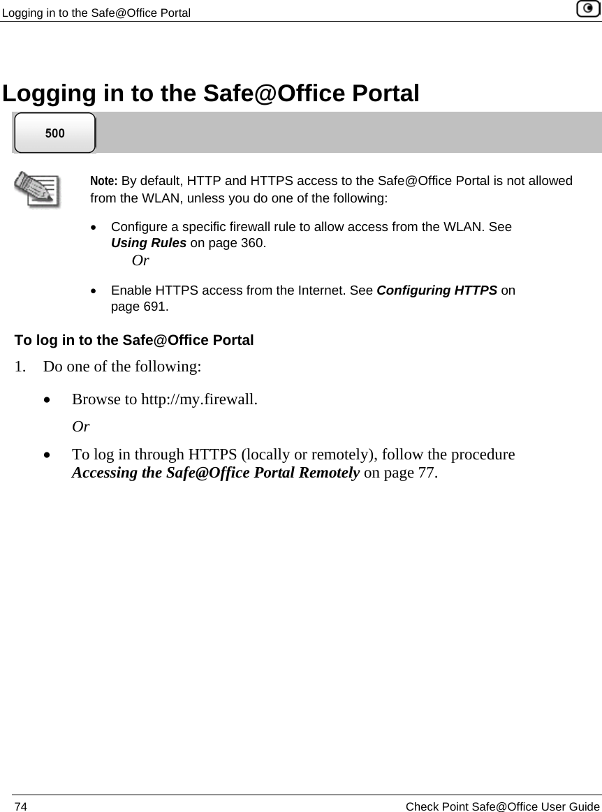
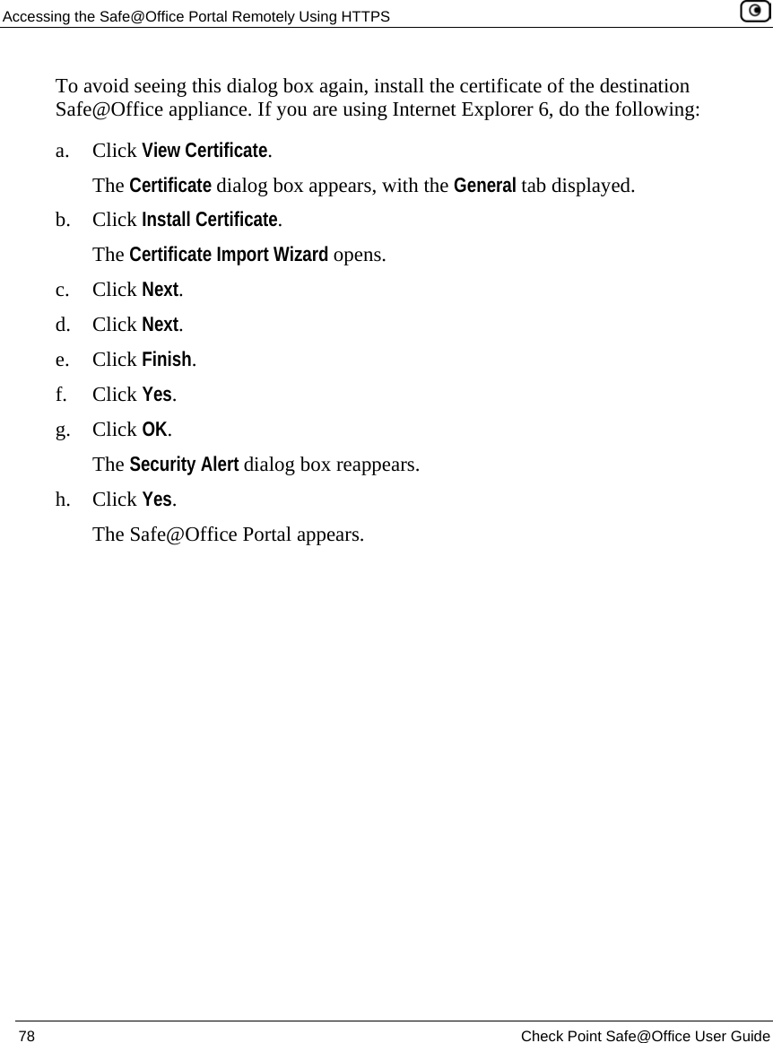
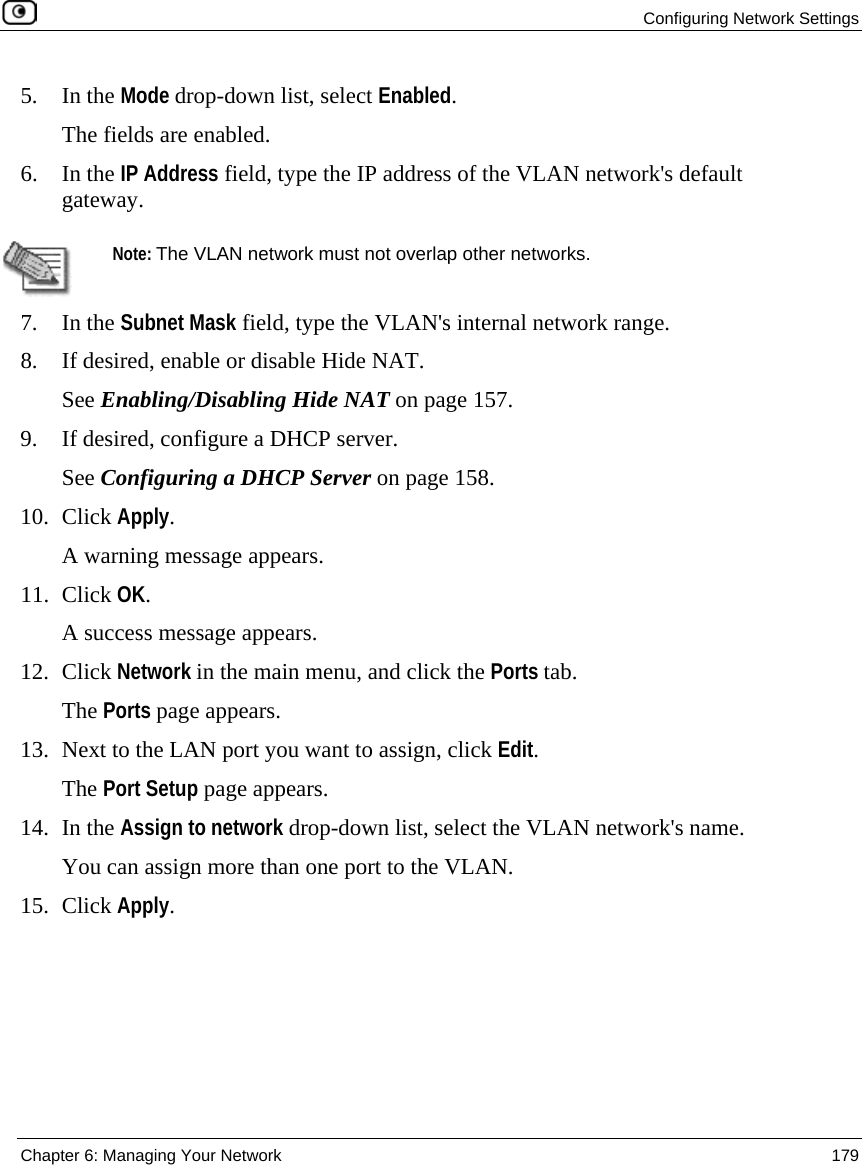
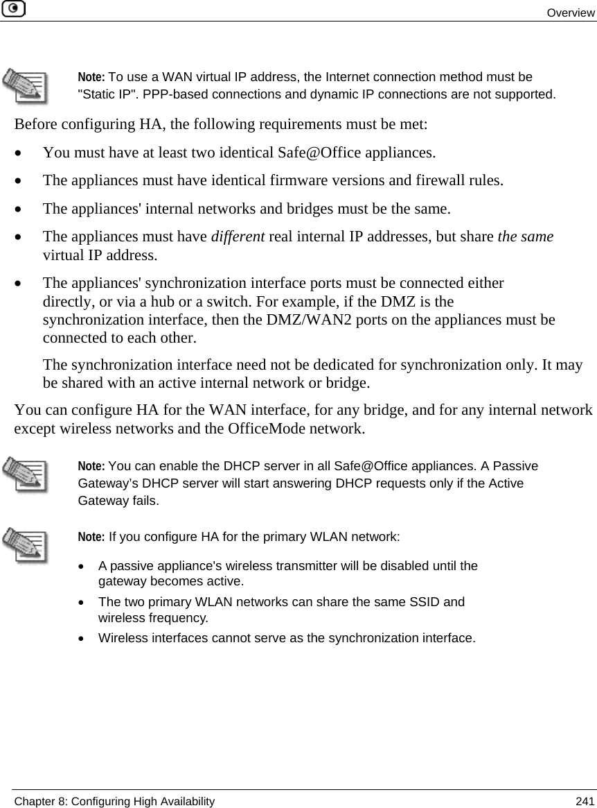
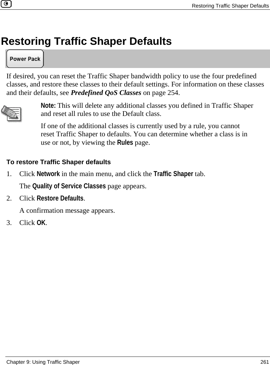
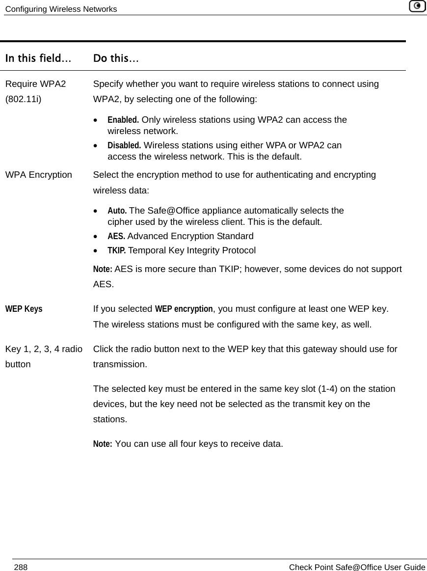
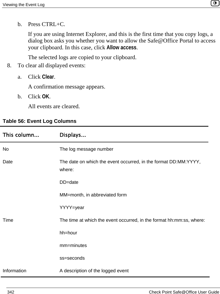
![Using Port-Based Security Chapter 13: Setting Your Security Policy 375 accessing sensitive company resources. You can also configure Traffic Shaper to grant members of the Quarantine network a lower amount of bandwidth than authorized users. You can choose to exclude specific network objects from 802.1x port-based security enforcement. Excluded network objects will be able to connect to the Safe@Office appliance's ports and access the network without authenticating. For information on excluding network objects from 802.1x port-based security enforcement, see Using Network Objects on page 185. Configuring Port-Based Security To configure 802.1x port-based security for a port 1. Do one of the following: • To use the Safe@Office EAP authenticator for authenticating clients, follow the workflow Using the Safe@Office EAP Authenticator for Authentication of Wired Clients on page 396. You will be referred back to this procedure at the appropriate stage in the workflow, at which point you can continue from the next step. • To use a RADIUS server for authenticating clients, do the following: 1) Configure a RADIUS server. See Using RADIUS Authentication on page 650. 2) Configure the clients for 802.1x authentication. For information, refer to your RADIUS server documentation. 2. To configure dynamic VLAN assignment, do the following: a. Add port-based VLAN networks as needed. See Adding and Editing Port-Based VLANs on page 178. b. Configure RADIUS option 81 [Tunnel-Private-Group-ID] on the RADIUS server. For information, refer to your RADIUS server documentation.](https://usermanual.wiki/SofaWare-Technologies/SBX-11GWLAN-7.manual-part-1/User-Guide-1184423-Page-391.png)