Solectek 58WAN1 DIGITAL TRANSCEIVER SYSTEM User Manual skyway5000 user guide Rev 0 2 fcc
Solectek Corporation DIGITAL TRANSCEIVER SYSTEM skyway5000 user guide Rev 0 2 fcc
Solectek >
Contents
manual

SKYWAY 5000 Series
User’s Guide
1. Introduction
Congratulations on your purchase of Solectek’s SKYWAY 5000 Series
Bridge/Router, a feature rich, best-in-class wireless solution. This User’s Guide
will describe the operation of your SKYWAY 5000 unit in detail.
SYSTEM FEATURES
• Based on field proven OFDM modulation allowing near line-of-sight
deployment and strong immunity to interference and multi-path
problems.
• Data rates from 6 Mbps to 108 Mbps
• High power radio (400mW) and improved radio sensitivity for best-in-
class link ranges – over 10 miles with only 1 foot panel antenna
• Power over Ethernet (POE) for easy cabling with a single outdoor CAT5
cable.
• All-in-one integrated enclosure that houses everything, including
antenna, radio, amplifier, and POE module. Mount one thing and you
are done.
• Latest AES encryption on board to provide the strongest security ad
ultimate data protection.
• Client access control via MAC address filtering
Package Contents
• SKYWAY client unit
- 5100 Short range
- 5300 Mid Range
- 5500 Long Range
• 24VDC Power Supply
• Power over Ethernet injector (the receiver is integrated inside the
SkyWay unit).
• CD-ROM containing documentation
• Registration Card
• Warranty and Compliance Card
NOTE: CAT5 Ethernet cable is not included in the package. UV-protected
Ethernet cables for outdoor use can be purchased from Solectek in a variety of
different length up to 300 feet. Also, a short Ethernet cable between the PC and
the POE injector is necessary for unit configuration. Please contact Solectek
Sales for details on purchasing Ethernet cables.
System Requirements
• Two CAT 5 UTP cables – straight cable if connecting to a hub/switch,
cross-over cable if connecting to a PC.
• A computer running TCP/IP over Ethernet.
• A SkyWay 5000 Series base unit (5600 or 5700) for a live testing of the
multipoint wireless network.
2. System Configuration
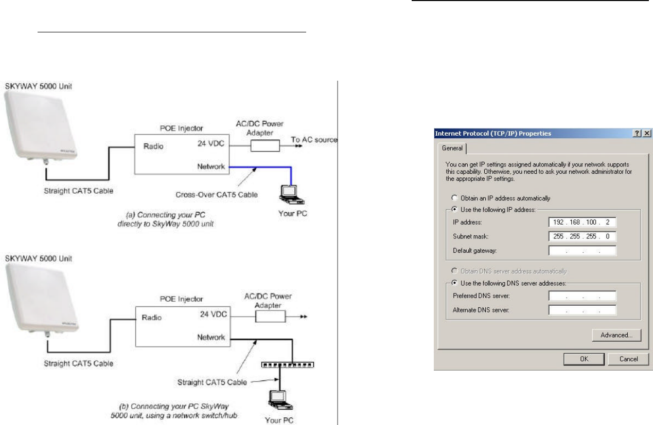
A. CONNECTING THE SKYWAY UNIT FOR CONFIGURATION
The following diagram explains the connection so that you can access the user
interface for configuration
• Power on your SKYWAY 5000:
1. Connect your SKYWAY and POE injector with an Ethernet cable.
2. Connect your PC to the POE injector using (a) crossover Ethernet
cable or (b) straight cable and a hub/switch.
3. Power on the POE injector using the supplied AC to 24V DC
adapter.
B. SET UP YOUR COMPUTER’S TCP/IP PROPERTIES
Open networking properties in your Windows OS. Find the TCP/IP setup window
of your wired Ethernet adapter. The details on how to set the IP address of
your computer’s Ethernet adapter are different, depending on Windows versions
(95/95/2000/Me/XP). Please consult your Windows OS documentation. Shown
below is the Windows 2000 TCP/IP Properties. Set the IP addresses to the
following values.
Ethernet’s IP Address: 192.168.0.2
Subnet Mask: 255.255.255.0
C. LOG-IN TO YOUR SKYWAY
• Connect your computer and SKYWAY 5000 unit using an Ethernet cable.
Use a straight CAT 5 cable if a network hub/switch is used or use a
cross-over cable if a computer is directed connect to the SKYWAY 5000
unit.
• Start a Web Browser on your computer (such as Netscape Navigator or
Microsoft Explorer).
• At the URL line, type in the following: http://192.168.0.1 to access the
Status screen below.
This screen can be referred back later for a summary view of the status of your
SKYWAY 5000 unit. At the initial boot-up out of the box, only the factory default
values should be displayed.
• Click on the login menu option located in the navy-blue left menu bar.
The following screen should appear.
• Type in solectek for the username and solectek for the password. You
can change the password later once you are in the interface screens.
Click start and you will see the left menu bar changed to the following.
g
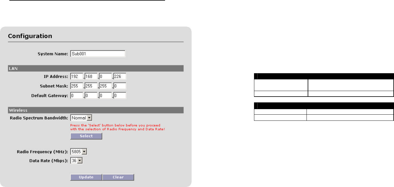
C. CONFIGURING THE BASIC SKYWAY 5000 PROPERTIES
• Click the Configuration menu option in the left menu bar to access the
following screen:
• System name
This is a description of the unit for convenience. This is not related to
the identification of the unit on your local area network.
• IP properties (LAN)
- IP Address: This is the IP address of the unit.
- Subnet Mask: This is the subnet mask of the unit.
- Default Gateway: the default gateway of the unit.
If you change any of the parameters, click on the Update button to
make the changes effective. You can also restore the previous setting
by clicking on Reset button.
• Wireless properties
- Radio Spectrum Bandwidth: There are two choices here:
Normal (default setting) and Wideband. The following is the
table for available radio frequency and data rate for each
option
If you change the Radio Spectrum bandwidth value, be sure to
click the Select button just below.
NORMAL (20MHz)
Frequency (MHz) 5735, 5755,5775,5795, 5815,
5845
Data Rate (Mbps) 54, 48, 36, 24, 18, 12, 6
WIDEBAND (40MHz)
Frequency (MHz) 5745, 5785, 5825
Data Rate (Mbps) 108, 96, 72, 48, 36, 24, 12
- Radio Frequency (MHz): the center frequency of the
selected frequency channel. In the Normal mode, each channel
is 20 MHz wide. In the wideband mode, it is 40 MHz.
- Data Rate: air transmission/receive data rates. Note that
different data rates are available for normal and wideband
modes, as detailed in the table above.
If you have edited any of the fields, click on the Update button on the
bottom to write the changes into system memory. Clicking on the Clear
button restores the original values before the changes.
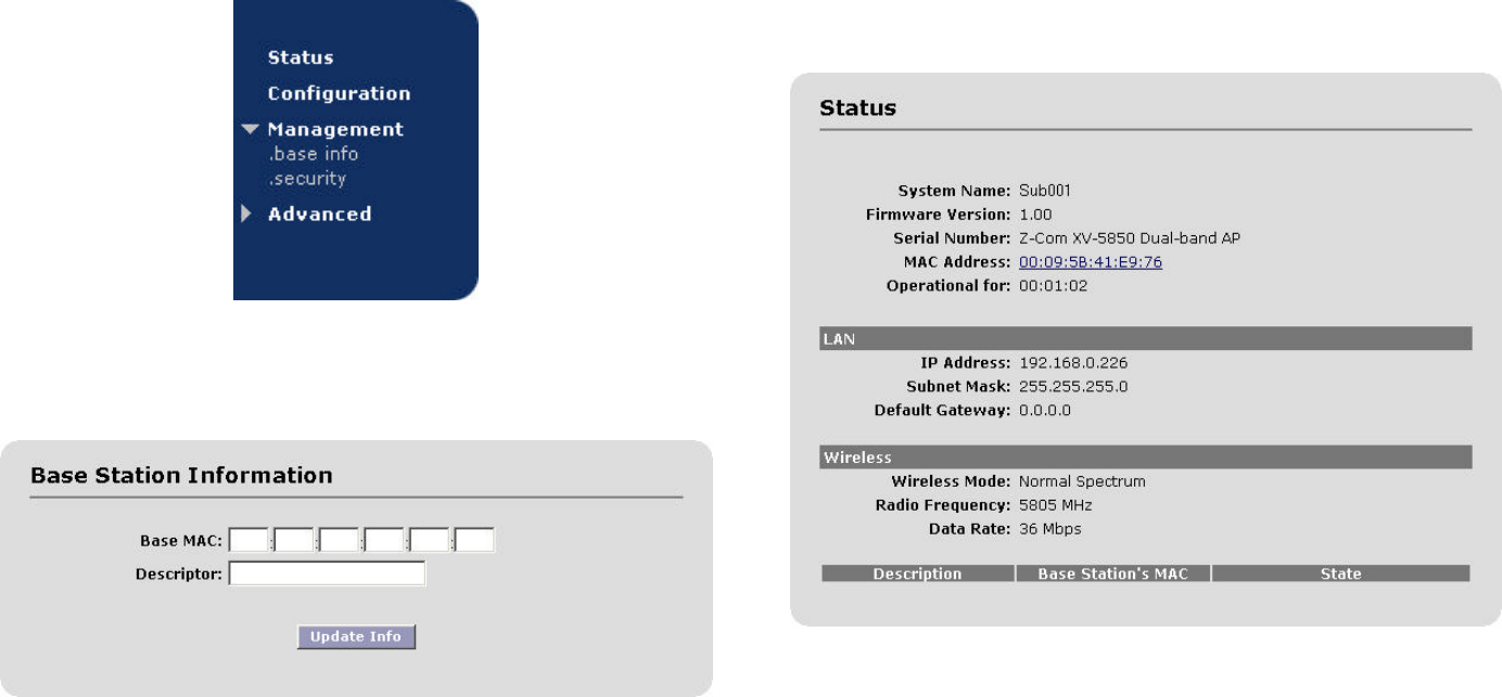
4. Base Station Access Configuration
• In the above screen, click on the Base info menu option under the
Management parent menu in the left menu bar to access the
following screen:
You can add an authorized client by typing in the following information.
- Base MAC: This is the hardware MAC address of the base station that
the client unit is intended to connect. This can be found in the user
interface of the base station unit.
- Description: Type in any description that will easily identify the user of
the base station with the above MAC address (e.g. main-street-
branch).
CAUTION: Descriptions must be a single word only. No spaces are
allowed.
5. Monitoring Operation
The basic status of the unit can be seen in the Status screen as seen in the
following screen.
``
This screen displays current values for the field items displayed. Go to the
Configuration screen if you would like to change any of these properties.
Three noteworthy items:
• Operational For: This is the time that the unit has been running. It
will reset to zero if the unit is rebooted
• MAC Address: this is the MAC address of the unit. Clicking on the
hyperlink will lead you to the wireless Status screen below.
• Description/Base Station’s MAC/ State: If you have configured the
base station, its desription and MAC address will show up here. You can
click on the MAC address hyperlink to see its wireless Status, similar to
the screen below.
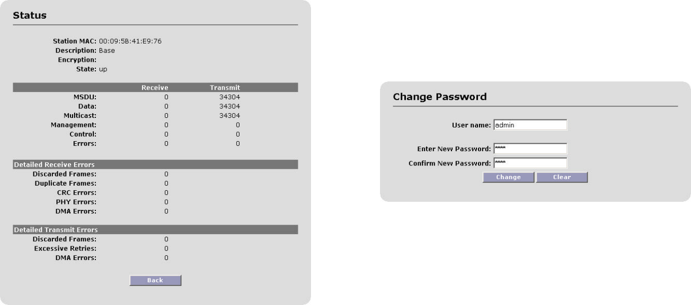
Better explanations here::
• Station MAC: the MAC address of the unit
• Description: indicates the description you have given to the unit in the
Configuration screen.
• Encryption: indicates whether encryption has been enabled.
• State: indicates the status of the radio operation.
• MSDU: Maximum Service Data Unit. Specifies the number fo packets
sent and received by the unit.
• Data/Control/Management: Packets can be either data, control,
management.
• Discarded Frames: Specifies the number of receive discarded frames.
• Duplicate Frames: Specifies the number of receive duplicate frames.
• CRC Errors: Specifies the number of receive CRC errors.
• PHY Errors: Specifies the number of receive PHY errors.
• DMA Errors: Specifies the number of receive DMA errors.
• Excessive Retries: Specifies the number of transmit excessive retries.
6. Changing Your Password
• Click on the Password menu option under the Advanced parent menu
in the left menu bar to access the following screen:
• Remote Management for HTTP
- User Name: This item is fixed to admin, and is not user
changeable.
- Password: User selected password.
Note: Please keep this password safe in your records. For your
convenience you can write down the password in Appendix C.
- Confirm Password: Used to validate user password and protect
you from mistyping your new password.
Click the Change button to activate your new password.
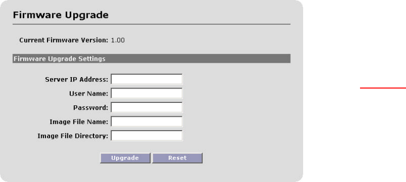
7. Upgrading the Software
NOTE: You need to install an FTP server program on your computer in
order to carry out the following upgrade procedure. You can use an FTP
program of your choice if you are familiar with such programs. In case you do
not have an access to one, Solectek has included FileZilla, an FTP server
program, on the installation CD. For details on the configuration of this
application, please refer to the document called FTP-Guide.pdf included on the
CD.
• Click on the Upgrade menu option under the Advanced parent menu
to see the following screen:
There may be newer software releases from Solectek from time to time. If you
would like to upgrade your unit, first obtain the new file from Solectek. The
current version will be posted on Solectek’s website.
Check to see if the current version available from Solectek is a newer version
than the one current installed on your SKYWAY 5000.
Save the new software file in a directory of your computer you can easily access.
For convenience, you may prefer to use the same computer that you use to
access the SKYWAY 5000 user interface, since the computer already has been
configured to be on the same network as the SKYWAY 5000.
• Software Version Check
- Server IP Address: The address of the computer that stores the
upgrade software file.
- User Name: User name used to login onto the upgrade FTP
server. For convenience, you may want to use anonymous login.
- User Password: Password used to login onto the upgrade FTP
server.
- Image File Name: The name of the binary file to be loaded onto
your SKYWAY 5000 unit.
- Image File Directory: Directory path to find the software
upgrade file on the FTP server,
NOTE: This path name is relative to the root path of the FTP
server.
Once you checked that the version is displayed correctly, click on the Upgrade
button. The upgrade should take less than a minute, and the unit will
automatically reboot once the upgrade is complete.
You will see the following reboot message once the unit starts a reboot process.
WARNING: Do not power down or unplug the unit during the upgrade
process.
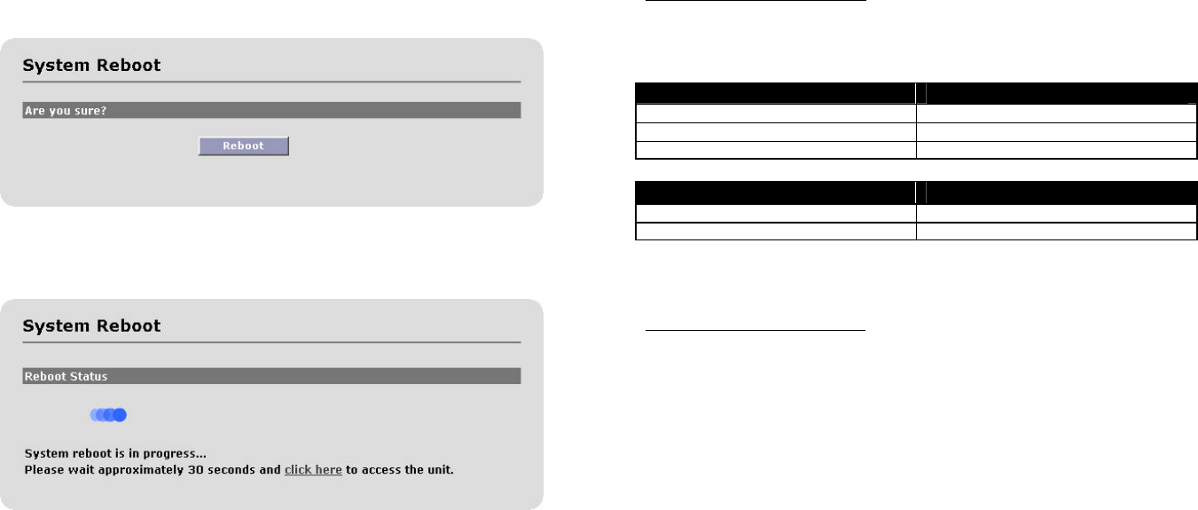
8. System Reboot
At times, you may want to reboot the unit for various reasons. This feature may
be convenient if the unit is mounted at a hard-to-reach location or when you
want to remotely reboot the unit without physically having to go to the site.
• Click on the Reboot menu option under the Advanced parent menu of the
left menu bar to access he following screen:
Click on the Reboot button to reset/reboot. The reboot process will take
approximately 30 seconds. Once the rebooting is done, you can use the Click
Here button below to access the user interface again.
Appendices
Appendix A
Factory Default Values
The following table details the factory default values. These are the values that
will be set initially at the factory or when you reset the configuration database.
WIRELESS
Radio Spectrum bandwidth normal
Channel 5805
Transmission Rate 36 Mbps
LAN
IP Address 192.168.0.1
Subnet Mask 255.255.255.0
Appendix B
Troubleshooting Guide
1. Can’t get a wireless connection with a client unit.
• Make sure that the client is added to the authorization list by typing in its
MAC address in the Add Station section.
• Make sure that the distance between the base and client units is within the
specified system range. A quick check of the signal strength and quality
indicators can help asses a marginal RF link. Poor indicator response may
be due to the following reasons:
- Your link distance has exceeded the unit’s capability: Review your
link budget to make sure that the system is able to handle the
distance. Use GPS devices to accurately determine the link distance
first. If you are unsure about the link budget, you may contact
Solectek Technical Support for help.
- Antenna misalignment: your antennas need to be aligned correctly
at each others bore site for you to get the best results in signal
strength.
- Radio interference: The radio activity in the environment is too
strong and may interfere with your signals. You may try to
determine the source by using a spectrum analyzer and a
directional antenna.

2. Can’t access the SKYWAY 5000 over Ethernet from my PC.
• Make sure the Ethernet connection is properly established.
• Make sure that the right IP address is used. Please refer to Section 2:
System Configuration for setting up the right IP addresses for your PC
and SKYWAY 5000 unit.
3. Can’t access the Internet through the SKYWAY 5000 unit.
• First, make sure that the wireless connection is established. Good RF
conditions need to be established between the units’ radios. MAC address of
the other unit needs to be correctly typed in at both the base and sub units.
• From a PC on the client unit side, pings the IP address of the SKYWAY 5000.
If this does not work, the wireless may still not be properly established or
the LAN IP setting is not correctly set between the SKYWAY 5000 and client.
• Ping a known IP address on the Internet, such as Yahoo’s IP address,
66.218.71.81. (From the DOS prompt command line, type “ping
66.218.71.81”). If this does not work, you have a problem getting out to
the Internet. Make sure that the IP setting is set correctly between the
SKYWAY 5000 and the surrounding IP network. Check with your IT
administrator or ISP to see if the Internet connection is up and running.
• If you can ping an Internet IP address, but still cannot browse the Internet,
make sure the DNS is set correctly on your network. Check with your IT
administrator or ISP for proper DNS setting for your wireless network.
Appendix C
For your records please record following items about your unit and keep it safe
in your records:
Username
and
Password:
Encryption
key:
Information contained in this document is subject to change without
notice. Solectek Corporation shall not be liable for errors contained
herein or for incidental or consequential damage in connection with the
furnishing, performance, or use of this material. Reproduction,
adaptation, or translation without prior written permission is prohibited,
except as allowed under the copyright laws.
Solectek Corporation makes no warranty of any kind with regard to this
material, including, but not limited to, the implied warranties or
merchantability and fitness for a particular purpose.
NOTE: Changes or modifications not expressly approved by
Solectek could void the user’s authority to operate the equipment.
SKYWAY, and Solectek are a registered trademark of Solectek Corporation.
HyperTerminal is the trademark of Hilgraeve, Inc. Windows is the trademark of
Microsoft Corp.
Copyright 2003, Solectek Corp. All rights reserved.
Part Number: Revision 0.2 (September 2003)