Sony Group BM153 Bluetooth Module User Manual SPEC BM153 V4 6 10012013
Sony Corporation Bluetooth Module SPEC BM153 V4 6 10012013
UserManual.wiki
>
Sony Group
>
BM153 User Manual
>
BM153_User Manual_REV3
Contents
1.
BM153_User Manual_REV3
2.
BM153_User Manual_REV 65298
BM153_User Manual_REV3
Navigation menu
Upload a User Manual
Namespaces
Wiki Guide
HTML
PDF
Info
Views
User Manual
Discussion / Help
Navigation
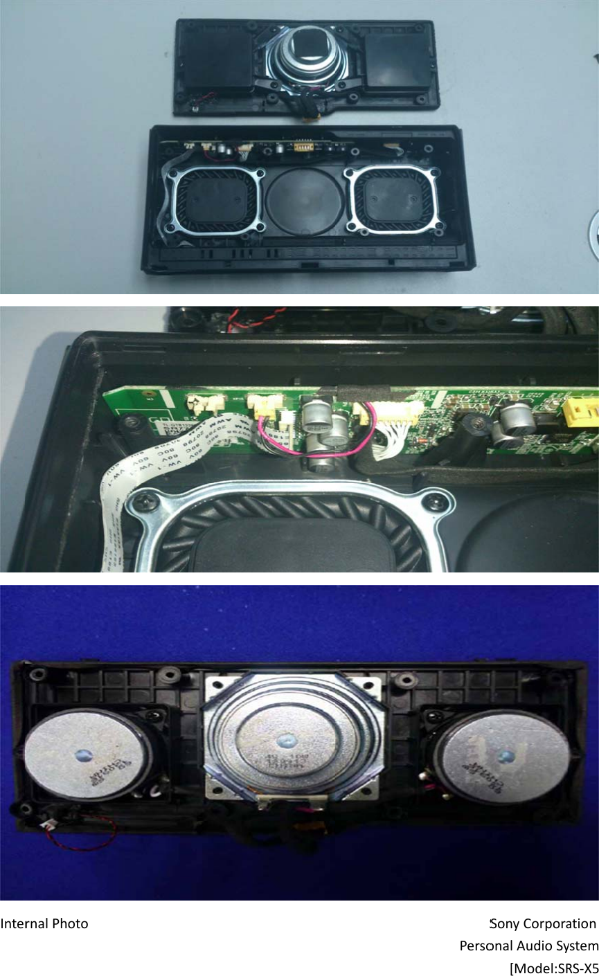
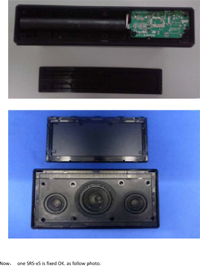
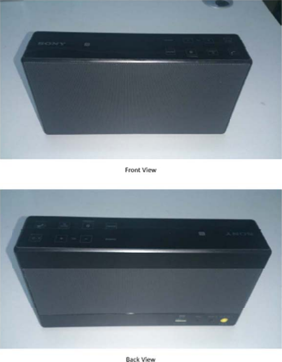
![InterInterrnalPhotornalPhotoSPersoSPersoSonyCorporaonalAudioSy[Model:SRSonyCorporaonalAudioSy[Model:SRationystemS‐X5]ationystemRS‐X5](https://usermanual.wiki/Sony-Group/BM153.BM153-User-Manual-REV3/User-Guide-2130695-Page-8.png)