Sounding Audio AWM914 Car Audio with Bluetooth User Manual AWM 914 Manual
Sounding Audio Industrial Ltd. Car Audio with Bluetooth AWM 914 Manual
UserManual.wiki
>
Sounding Audio
>
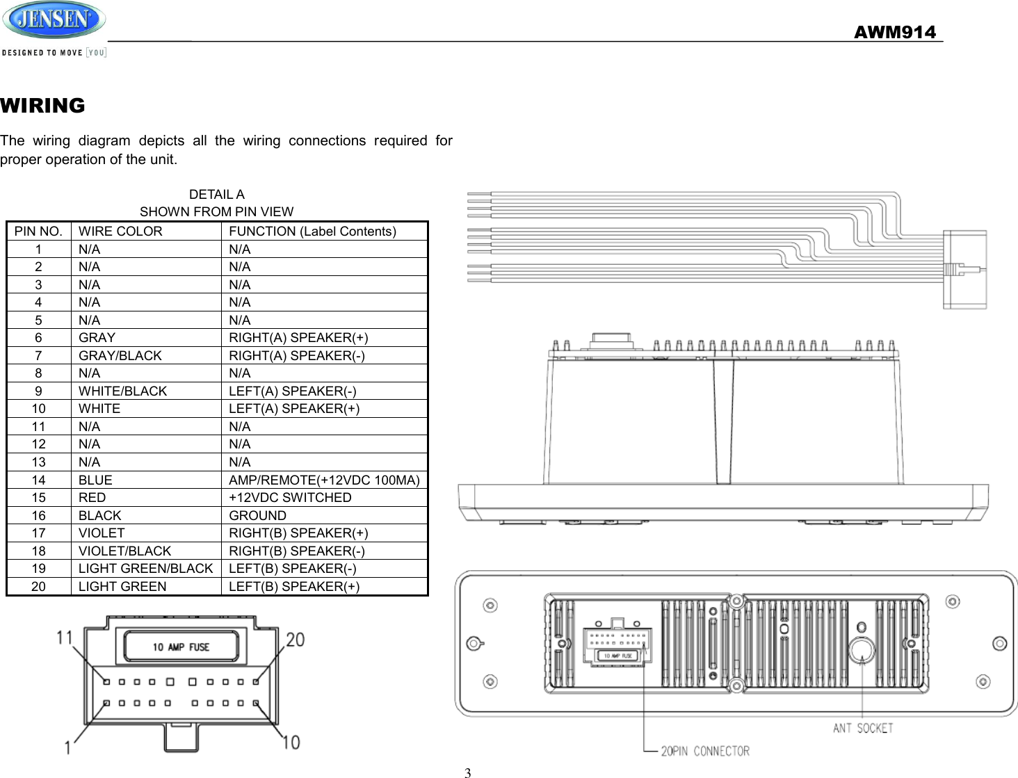
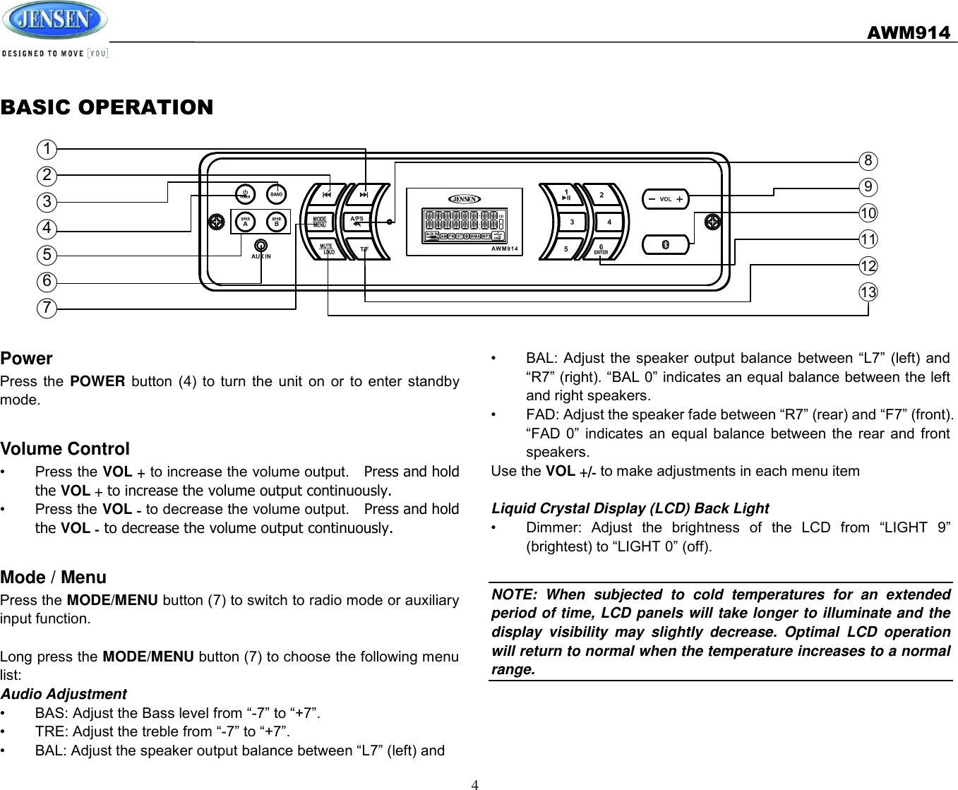
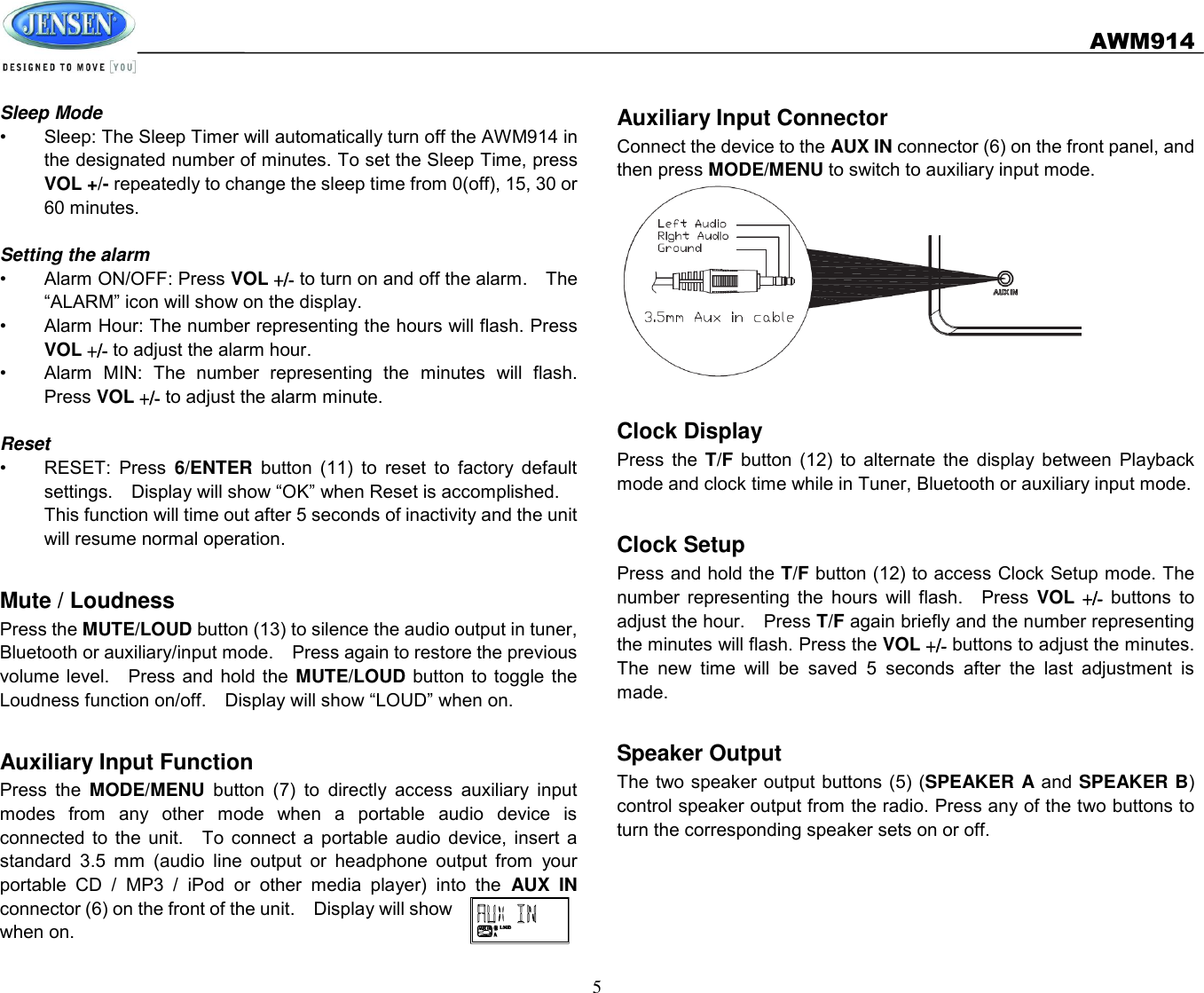
AWM914 User Manual
User Manual
Navigation menu
Upload a User Manual
Namespaces
Wiki Guide
HTML
PDF
Info
Views
User Manual
Discussion / Help
Navigation