Spacelabs Healthcare 010-0914-00 User Manual Wireless Ethernettm
Spacelabs Healthcare, Inc. Wireless Ethernettm
UserManual.wiki
>
Spacelabs Healthcare
>
010-0914-00 User Manual
>
User Manual 1 of 3
Contents
1.
User Manual 1 of 3
2.
User Manual 2 0f 3
3.
User Manual 3 of 3
User Manual 1 of 3
Navigation menu
Upload a User Manual
Namespaces
Wiki Guide
HTML
PDF
Info
Views
User Manual
Discussion / Help
Navigation
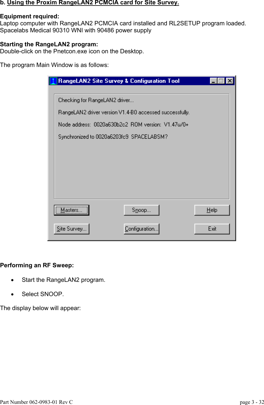
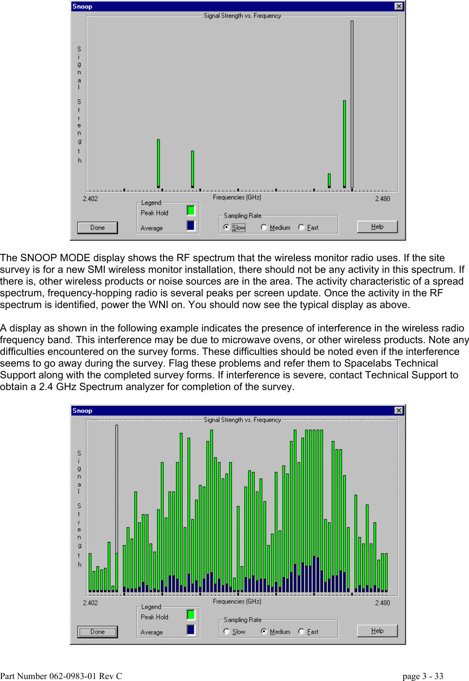
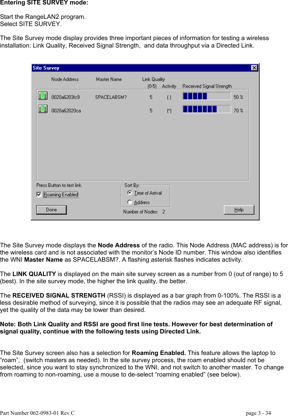
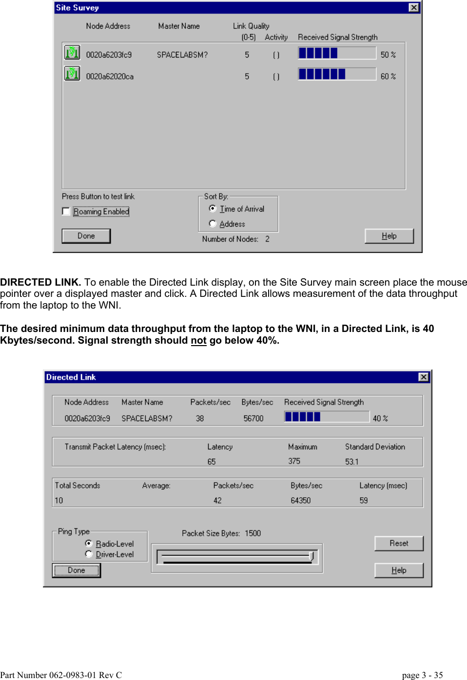
![Based on the complex physical shape and the site survey of the coverage area, it is determined that we need two masters. The survey shows that X1 master can cover; TR1, TR2, TR3, TR4, TR10, TR11, TR12, ER5, ER4, ER3, the lower hallway, the middle hallway, the right half of the upper hallway, the PCMS central area and the observation area. Thus we need X2 to cover TR5, TR8, ER8, ER7, ER6, the left side hallway, and the left half of the upper hallway. We may notice X2 will also cover ER5, the right half of the upper hallway, the left end of the lower hallway, TR4 and possibly TR12. IMPORTANT: As mentioned earlier, one WNI is limited to a maximum of 20 waveforms at a time. If this parameter is exceeded, unacceptable numbers of waveform dropouts will occur. The two WNI’s in this example may not be adequate if the number of wireless monitors is increased, even though they provide full area coverage. Installation options for this example: • Use a different channel for each master and Auto-channel select mode for the slaves. This allows more flexibility to reposition masters to optimize coverage without concern that the masters would interfere with each other. This illustrates the ability of a monitor to roam from one channel master to another. • Use a single fixed channel for both masters and all slaves. If both X1 and X2 are on the same channel, and as long as masters on the same channel cannot directly receive other master signals, the setup will be valid. [Don’t forget the floors above and below in channel selection. Masters on these floors may have overlap on this floor.] If the x-ray room needs coverage, a separate master, on a third channel, would need to be installed in the “X-RAY” room, and the slaves must use auto-channel select mode. If the installation described above included twenty monitors, the installation options would be as follows: • If the monitors are not mobile, and x-ray is not covered, it would be possible to use two WNI’s on two different channels (also keeping in mind the limit of 20 parameters per WNI. If the monitors are going to be set for more than 2 outbound parameters, more than 2 WNI’s may be needed). The slaves need to be positioned so that they are equally divided between the two WNI’s according to the cell boundary of each WNI. Half of the Wireless bedsides must be set to one channel, and half on another channel. • If the monitors are mobile, and must function from any room in the unit, then a pair of WNI’s must be installed where the X1 and X2 master locations are indicated. The slaves must use auto-channel select mode. Part Number 062-0983-01 Rev C page 3 - 23](https://usermanual.wiki/Spacelabs-Healthcare/010-0914-00.User-Manual-1-of-3/User-Guide-236642-Page-23.png)