Spectralux 14114 Dlink+ w/CPDLC. All-in-one data communications, CPDLC and ACARS in a single LRU User Manual SP Avionics Logo v1 ai
Spectralux Corporation Dlink+ w/CPDLC. All-in-one data communications, CPDLC and ACARS in a single LRU SP Avionics Logo v1 ai
Contents
- 1. Installation Manual
- 2. Users Manual 1
- 3. Users Manual 2
- 4. Users Manual
Installation Manual
INST-14114-1
Dlink+ w/CPDLC Installation Manual
Document Number: INST-14114-1 Rev. - Page 1 of 25
Installation Manual
For Dlink+ w/CPDLC
SLC Doc Number INST-14114-1
Revision -
12335 134th Court NE
Redmond, WA 98052
USA
Tel: (425) 285-3000
Fax: (425) 285-4200
Email: info@spectralux.com
RESTRICTION ON USE, PUBLICATION, OR DISCLOSURE OF PROPRIETARY INFORMATION
This document contains information proprietary to Spectralux Corporation, or to a third party to which Spectralux Corporation may
have a legal obligation to protect such information from unauthorized disclosure, use, or duplication. Any disclosure, use, or
duplication of this document or of any of the information contained herein for other than the specific purpose for which it was
disclosed is expressly prohibited, except as Spectralux Corporation may otherwise agree in writing.
Preparer:
Engineer:
Program Manager:
Quality Assurance
Digitally signed by Larry S
DN: cn=Larry S, o=Systems Engineer,
ou=Engineering, email=larrys@spectralux.com, c=US
Date: 2011.12.19 18:16:19 -08'00'
Digitally signed by Larry S
DN: cn=Larry S, o=Systems Engineer,
ou=Engineering, email=larrys@spectralux.com, c=US
Date: 2011.12.19 18:16:29 -08'00'
Digitally signed by Robert W Bernstein
DN: cn=Robert W Bernstein, o=Director of Engineering,
ou=Engineering, email=bobb@spectralux.com, c=US
Date: 2011.12.19 18:10:15 -08'00'
Digitally signed by David Cierebiej
DN: cn=David Cierebiej, c=US, o=Software Quality Analyst,
ou=Quality Assurance, email=davidc@spectralux.com
Date: 2011.12.19 16:57:56 -08'00'

INST-14114-1
Dlink+ w/CPDLC Installation Manual
Document Number: INST-14114-1 Rev. - Page 2 of 25
CHANGE RECORD
Paragraph Description Of Change Approval/
Date Revision
All Initial release L.Sinn
12/19/2011
-
SVN
21090

INST-14114-1
Dlink+ w/CPDLC Installation Manual
Document Number: INST-14114-1 Rev. - Page 3 of 25
Table of Contents
1Introduction .......................................................................................................................................... 4
2Description and Operation .................................................................................................................. 4
3Prepare for Installation ........................................................................................................................ 6
4Installation and Test .......................................................................................................................... 10
Appendix A – 14114-1-XX Environmental Qualification Form .............................................................. 25

INST-14114-1
Dlink+ w/CPDLC Installation Manual
Document Number: INST-14114-1 Rev. - Page 4 of 25
1 Introduction
A. This document provides the information required to install the following Dlink+ w/CPDLC part
numbers, including all modification levels:
• 14114-1-XX
“XX” designates the color of the Dlink+ w/CPDLC with a Keyboard Sub-Assembly (front panel). The
only difference is the color of the front panel. Therefore, throughout this document, we refer to the
Dlink+ w/CPDLC Part Number simply as 14114-1. The information contained in this document applies
to all color variants of the Dlink+ w/CPDLC.
B. For required test and repair instructions specific to the Dlink+ w/CPDLC, reference Spectralux
Component Maintenance Manual 23-20-02. The instructions and procedures defined in the CMM are
necessary to ensure the product operates satisfactorily over its service lifetime. Shop level repair is
limited to replacement of Circuit Boards.
C. Spectralux Corporation contact information:
12335 134th Court NE, Redmond, WA 98052, USA
Telephone: +1 425-285-3000
Fax: +1 425-285-4200
Cage Code: 51896
D. The conditions and tests for TSO approval of this article are minimum performance standards. Those
installing this article, on or in a specific type or class of aircraft, must determine that the aircraft
installation conditions are within the TSO standards. TSO articles must have separate approval for
installation in an aircraft. The article may be installed only according to 14 CFR part 43 or the
applicable airworthiness requirements.
2 Description and Operation
A. The Dlink+ w/CPDLC provides Aircraft Communication Addressing and Reporting System (ACARS)
and Controller Pilot Data Link Communications (CPDLC) message capability in one cockpit mounted
Line Replaceable Unit (LRU). The Dlink+ w/CPDLC is a Class 7 transceiver that can be tuned to any
25 kHz channel over the frequency range of 118.000 to 136.975 MHz with a RF output power on all
frequencies shall not be less than 10 watts in the air.
B. The Dlink+ w/CPDLC works in conjunction with a device called the “Personality Module” mounted
separately. The personality module is a serial EEPROM that houses the unit’s configuration and
database. When the unit is powered ON, the unit reads the data from the personality module. The
configuration information determines the aircraft specific information such as tail number and the
hardware configuration (what IO ports are connected and the type of devices connected to those
ports). The personality module is attached to the aircraft in which the Dlink+ w/CPDLC is installed
and connects to the Dlink+ w/CPDLC when installed on the aircraft via the Dlink+ w/CPDLC 11 pin
Mil-Circular connector. Any Dlink+ w/CPDLC that is connected to a given personality module will
operate with the same configuration.
C. The Dlink+ w/CPDLC is cooled through its case and a rear mounted cooling fan. Under normal
operating conditions no additional cooling is required.
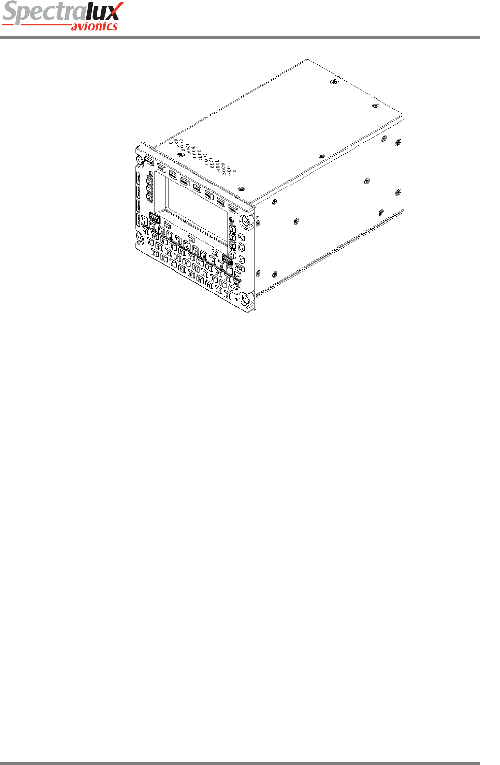
D. Figure 2-1 is a perspective view of the Dlink+ w/CPDLC.
INST-14114-1
Dlink+ w/CPDLC Installation Manual
Document Number: INST-14114-1 Rev. - Page 5 of 25
Figure 2-2 - Perspective View of Dink+ (14114-1 shown)
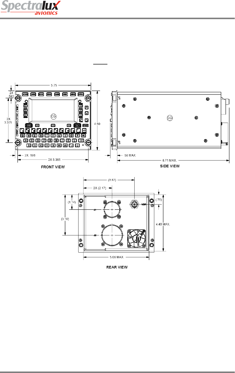
E. General Specifications
• DZUS Mount 5.75” W x 4.5” H x 8.71” D (14.6 cm W x 11.4 cm H 22.1 cm D)
• Weight: 5.1 pounds (2.3 kg)
• Operating Temperature: -15°C to +55°C
• Short Time Operating Temperature: -40ºC to +70ºC with reduced power output at greater than
+55ºC
• Storage Temperature: -55°C to +85°C
• Environmental: DO-160E
F. Inputs
• 28 VDC (20.5 – 32.2 VDC), 25 watts standby, 160 watts transmitting
• RF (118 – 136.975 MHz)
• ARINC 429 Receivers 8
• Discretes 8
• 10 Base-T Ethernet 1
G. Outputs
• RF (118 – 136.975 MHz), 10 watts minimum
• ARINC 429 Transmitters 4
• Discretes 4
• 10 Base-T Ethernet 1

INST-14114-1
Dlink+ w/CPDLC Installation Manual
Document Number: INST-14114-1 Rev. - Page 6 of 25
3 Prepare for Installation
A. Installations must be performed per the requirements of FAA Advisory Circular (AC) 43.13-1B and
43.13-2B or later current revisions of these documents and any applicable documents referenced in
these ACs. The ACs describe installation processes including how to locate the Dlink+ w/CPDLC,
antenna requirements, wiring requirements, cable routing, mounting, circuit breaker information and
other required steps. The ACs also include inspection steps and best practice guidance. Personnel
who perform installations must be qualified and must meet all applicable FAA requirements.
B. The Dlink+ w/CPDLC is designed to fit into a standard, 5.75” (14.6 cm) by 4.5” (11.43 cm) Dzus rail
mounting slot. There are two military circular connectors (one 11 pin connector and one 61 pin
connector) and one RF TNC connector mounted to the rear of the unit. These connectors provide all
input/output connections to the Dlink+ w/CPDLC. Tables 1 and 2 show the 11 pin and 61 pin
connections.
C. Connections:
• The Dlink+ w/CPDLC RF output is a TNC connector that is used to connect to the coaxial cable
running to an aircraft mounted VHF antenna. Use double-shielded coaxial cable RG400, or
equivalent.
The antenna will be vertically polarized and have a frequency range of 118.000-136.975 MHz.
The antenna installation should conform to the applicable RTCA DO-224, Signal-in-Space
Minimum Aviation System Performance Standards for Advanced VHF Digital Data
Communications Including Compatibility with Digital Voice Techniques. The VHF Communication
antenna must have a 50-ohm RF impedance with a maximum VSWR of 3:1. Maximum loss into
the antenna must be less than 5.5 dB. The maximum VSWR presented to the Dlink+ w/CPDLC
TNC connector must be 2:1 tested per RTCA DO-281.
• The 11-pin connector provides the power/ground, 5 Volt dimming bus, and personality module
interfaces. The 11-pin connector mates with an MS3476L18-11S connector with appropriate
strain relief. This mating connector uses #16 socket crimp contacts (M39029/5-116).
Non-emergency +28 VDC aircraft power is routed to the connector. This power is provided using
one or two 16 AWG wires. The wires are terminated with MS39029/5-116 contacts. The
contacts are inserted into the connector’s “A” and/or “L” positions. If both “A” and “L” connector
positions are used, they must be wired to the same power bus. A 7.5 amp circuit breaker must be
used for protection.
The 28 VDC return (ground) is provided using one or two 16 AWG wire(s). The wires are
terminated with MS39029/5-116 contacts. The contact is inserted into the connector’s “B” and/or
“K” position.
Chassis ground is connected using one 14 AWG wire into the connector’s “J” position.
The personality module may be tie wrapped to the power cable or mounted to a nearby bulkhead.
See installation instructions below.
• The 61-pin connector provides the unit’s signal interfaces. The 61-pin connector mates with an
MS3476L24-61S connector. This connector uses #20 socket crimp contacts (M39029/5-115).
Single wires for discretes and paired wires for ARINC 429 signals and for ethernet signals must
be used.
The unit was DO-160E qualified in two configurations.
One configuration used shielded single wires and shielded twisted pairs with the shields attached
to ground at both ends. Glenair backshells from the 40 series were used at the Dlink+ w/CPDLC
for short termination of shields to chassis.
INST-14114-1
Dlink+ w/CPDLC Installation Manual
Document Number: INST-14114-1 Rev. - Page 7 of 25
The other configuration used unshielded single wires and shielded twisted pairs. The shields
were grounded at both ends. At the Dlink+ w/CPDLC end, grounding was accomplished by
connecting the shields to ground pins of the 61-pin connector. The cable was stabilized by a
strain relief. To achieve passing RF emissions results with this configuration, it was necessary to
install Quell Corp. 18-11.9 and 24-61.35 FilterSeals in J1 and J2, respectively.
Other grounding and shielding schemes may be acceptable.
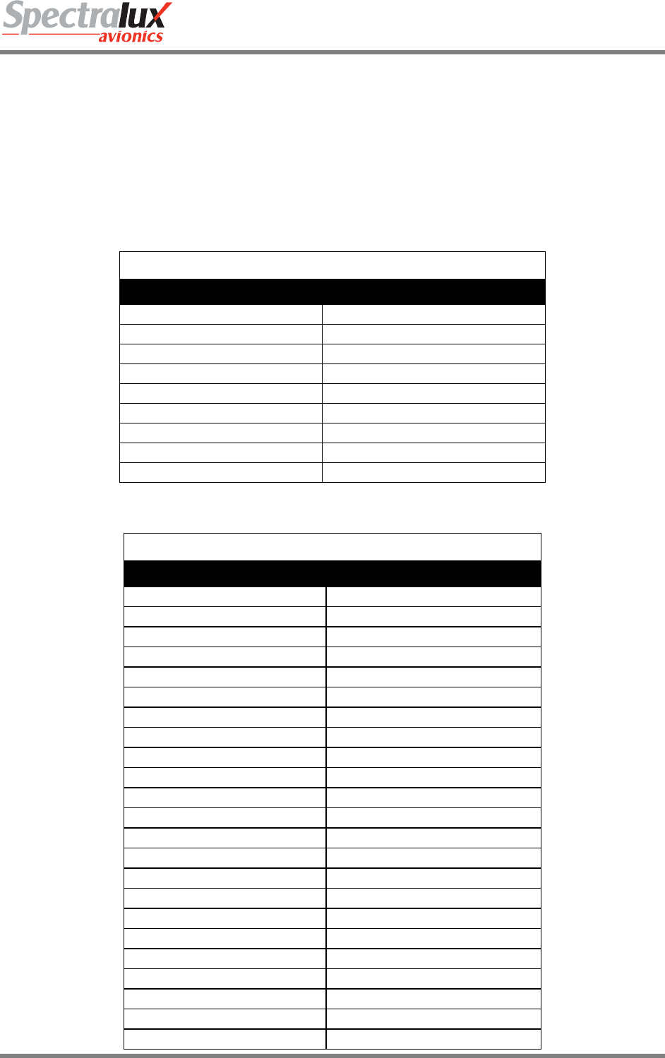
Table 1 - 11-Pin Connector Connections
11 Pin Military Circular Connections – Identifier - J1
Description Pin(s)
+28V DC POWER A, L
28V DC RETURN B, K
Personality Module CLOCK C
Personality Module DATA D
Personality Module +3.3V E
Personality Module GND F
Cockpit Dimming 5V G
Cockpit Dimming COMMON H
Chassis GROUND J
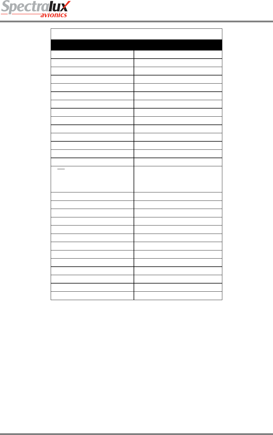
Table 2 - 61-Pin Connector Connections
61 Pin Military Connections - Identifier– J2
Description Pin(s)
Ground A, F, N, a, i, p, s, x, z, GG, KK
429 Transmit + Channel 1 AA
Ethernet Transmit + B
429 Receive + Channel 8 b
429 Transmit - Channel 1 BB
Ethernet Transmit - C
429 Receive - Channel 8 c
429 Receive + Channel 1 CC
Ethernet Receive + D
429 Receive + Channel 7 d
429 Receive - Channel 1 DD
Ethernet Receive - E
429 Receive - Channel 7 e
429 Receive + Channel 2 EE
Not Used f
429 Receive - Channel 2 FF
Output Discrete 1 G
Input Discrete 7 g
Output Discrete 2 H
Input Discrete 8 h
Not Used HH
Input Discrete 1 j
Output Discrete 3 J
INST-14114-1
Dlink+ w/CPDLC Installation Manual
Document Number: INST-14114-1 Rev. - Page 8 of 25
61 Pin Military Connections - Identifier– J2
Description Pin(s)
Not Used JJ
Input Discrete 2 k
Output Discrete 4 K
Input Discrete 5 L
Not used LL
Input Discrete 6 M
Not used m
Not used MM
Input Discrete 4 n
Not Used NN
429 Transmit + Channel 2 P
Not Used PP
Not Used q
429 Transmit - Channel 2 R
T/ R TRIGGER
(Factory test use only. Not
used on aircraft)
r
429 Receive + Channel 3 S
429 Receive - Channel 3 T
429 Transmit + Channel 3 t
429 Receive + Channel 4 U
429 Transmit - Channel 3 u
429 Receive - Channel 4 V
429 Transmit + Channel 4 v
429 Receive + Channel 5 W
429 Transmit - Channel 4 w
429 Receive - Channel 5 X
429 Receive + Channel 6 Y
Input Discrete 3 y
429 Receive - Channel 6 Z
D. Figure 3-1 provides the front, rear and side views.
E. Items required for installation will depend on the specific aircraft and situation. Installation items are
not furnished by Spectralux. The following items are required and should be selected and installed
per this document and the Advisory Circulars referenced above.
• Mounting hardware for Dlink+ w/CPDLC and personality module.
• Antenna with sealant.
• Cabling with proper connectors, routing and service loops.
F. Installation approval - The conditions and tests required for TSO approval of the Dlink+ w/CPDLC and
antenna are minimum performance standards. It is the responsibility of the installer to determine that
the aircraft installation standards for a specific type or class of aircraft are in compliance with all
applicable airworthiness standards. Installation in environments in excess of those listed in Appendix
A is not permitted.
INST-14114-1
Dlink+ w/CPDLC Installation Manual
Document Number: INST-14114-1 Rev. - Page 9 of 25
G. Before installation, perform a pre-modification avionics systems test to verify that the systems that will
be connected to the Dlink+ w/CPDLC are working properly in accordance with their appropriate
maintenance manuals.
H. Visually inspect the Dlink+ w/CPDLC packaging for evidence of shipping damage. Carefully unpack
and inspect the Dlink+ w/CPDLC and associated equipment and verify all the items have been
received. Reject any damaged items before beginning installation. Retain the shipping container and
packaging materials in case reshipment or return to the supplier is necessary.
Figure 3-2 - Front, Side and Rear View (Dimensions in Inches)
I. The following in needed to configure and load the database:
a. Laptop with ConfigurationLoader software and Ethernet cable.
b. Aircraft specific information:
i. Aircraft Registration (Tail number, 7 chars max)
ii. ICAO Address (6 characters)
iii. Avionics Indication Display Capability (3 characters)
iv. NSAP Address (40 characters)
v. Agency Code (2 chars)

INST-14114-1
Dlink+ w/CPDLC Installation Manual
Document Number: INST-14114-1 Rev. - Page 10 of 25
4 Installation and Test
A. Install the Dlink+ w/CPDLC system components per the referenced ACs:
• The Dlink+ w/CPDLC will be installed in available space in a standard 5.75” (14.6 cm) by 4.5”
(11.43 cm) Dzus rails mounting slot after all cables have been routed and connected.
Temporarily install in place and check for fit issues if necessary. Do not completely tighten
installation hardware until all system components and cables have been installed.
• VHF Antenna: If not already mounted, install the vertically polarized 118.000-136.975 MHz
antenna. The antenna installation must conform to the applicable RTCA DO-224, Signal-in-
Space Minimum Aviation System Performance Standards for Advanced VHF Digital Data
Communications Including Compatibility with Digital Voice Techniques and must have a 50-ohm
impedance with a maximum VSWR of 3:1.
¾ Measure the distance from the antenna to the back of the Dlink+ w/CPDLC and plan for
proper cable routing, securing and service loops.
¾ Cut the RF cable to length and terminate one end of the cable with a TNC plug for connection
to the Dlink+ w/CPDLC and the other end with the proper connector for attachment to the
antenna.
¾ Connect the RF cable to the 50-ohm interface on the antenna. Route the RF cable and verify
the VSWR does not exceed 2:1, per RTCA DO-281, when measured from the Dlink+
w/CPDLC end. Connect to the RF TNC connection on the back of the Dlink+ w/CPDLC.
¾ Ensure the antenna is properly sealed and the installation complies with the requirements of
the referenced ACs.
• Test mate samples of the proposed 11-pin and 61-pin connectors to the Dlink+ w/CPDLC to
ensure compatibility.
• Connect the 11-pin connector to provide power/ground, 5 Volt dimming bus, and personality
module interfaces:
¾ Mate the 11-pin connector to an MS3476L18-11S connector using #16 socket crimp contacts
(M39029/5-116).
¾ Route non-emergency +28 VDC aircraft power to the connector using one or two 16 AWG
wires. Terminate the wire(s) with the MS39029/5-116 contacts and insert the contacts into
the connector’s “A” and/or “L” positions. If two wires are used, both must be attached to the
same power bus. Protect the circuit using one 7.5 amp circuit breaker per AC 43.13-1B.
¾ Provide 28 VDC return (ground) using one or two 16 AWG wire and terminate the wires using
the MS39029/5-116 contacts and insert the contact into the connector’s “B” and/or “K”
positions. The length of the wire should be kept as short as possible, but always less than 3
feet (1 meter).
¾ The chassis ground is to be a 14 AWG wire in position “J”. The length of the wire should be
kept as short as possible, but always less than 3 feet (1 meter).
¾ If the personality module is tie wrapped to the power cable, the wires are 24 AWG and should
be no longer than 6 inches (15 cm). If the personality module is to be mounted on a nearby
bulkhead then the wiring must be two pairs of twisted shielded pairs up to 3 feet (1 m) long.
The +3.3V and Data lines should be in one pair and the GND and CLK should be in the other
pair with the shields tied to the GND at both ends of the wire.
• Connect the 61-pin connector to provide the unit’s signal interfaces:
INST-14114-1
Dlink+ w/CPDLC Installation Manual
Document Number: INST-14114-1 Rev. - Page 11 of 25
¾ Mate the 61-pin connector to an MS3476L24-61S connector using #20 socket crimp contacts
(M39029/5-115).
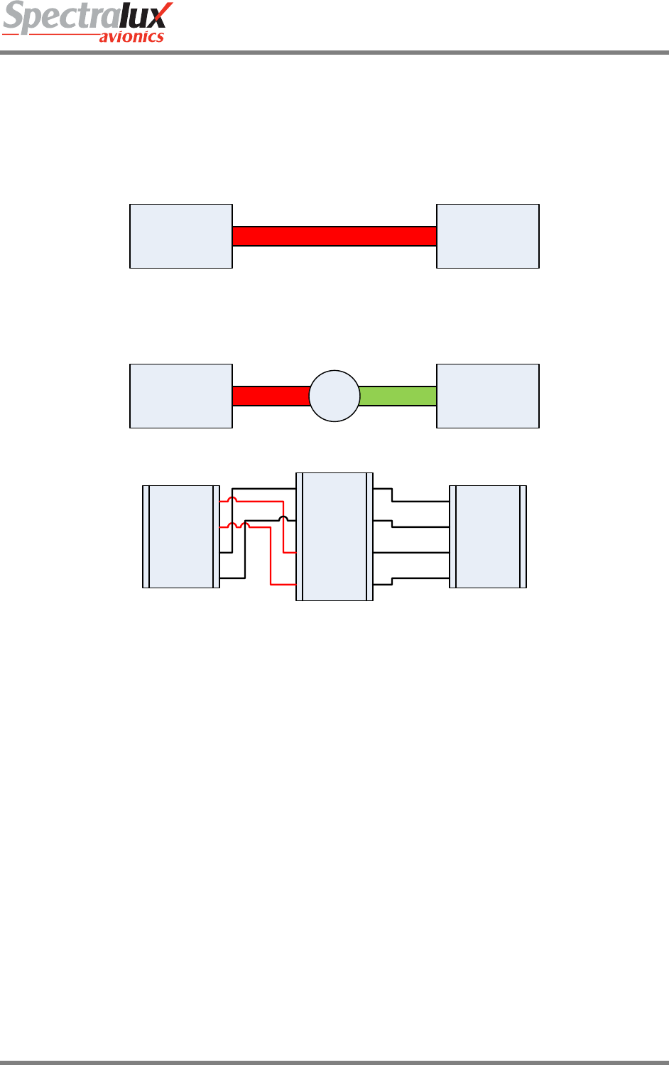
¾ The Ethernet pins are to be routed to a convenient bulkhead so there is easy access to the
Ethernet socket. Use CAT5 cable or equivalent to connect from the 61-pin socket to the
bulkhead RJ-45 socket and swap the transmit and receive lines so a standard Ethernet cable
can be used to connect to a PC.
Dlink+ w/
CPDLC
Dlink+ w/
CPDLC
Laptop
Computer
Laptop
Computer
Crossed StraightRJ45
Crossed
TX+ (B)
TX- (C)
RX+ (D)
RX- (E)
TX+ (1)
TX- (2)
RX+ (3)
RX- (6)
TX+
TX-
RX+
RX-
Figure 4-1 RJ45 Connection
¾ Refer to section 3C of this document for information about shielding.
• Secure power cables and interconnecting cables and wiring. Ensure cables are routed away
from interfering areas on the aircraft, are protected from chafing and have required service loops
per the referenced ACs.
• Inspect the Dlink+ w/CPDLC system installation per the referenced ACs.
• Complete the Dlink+ w/CPDLC system installation by tightening any temporarily installed
hardware.
B. Load the configuration and database
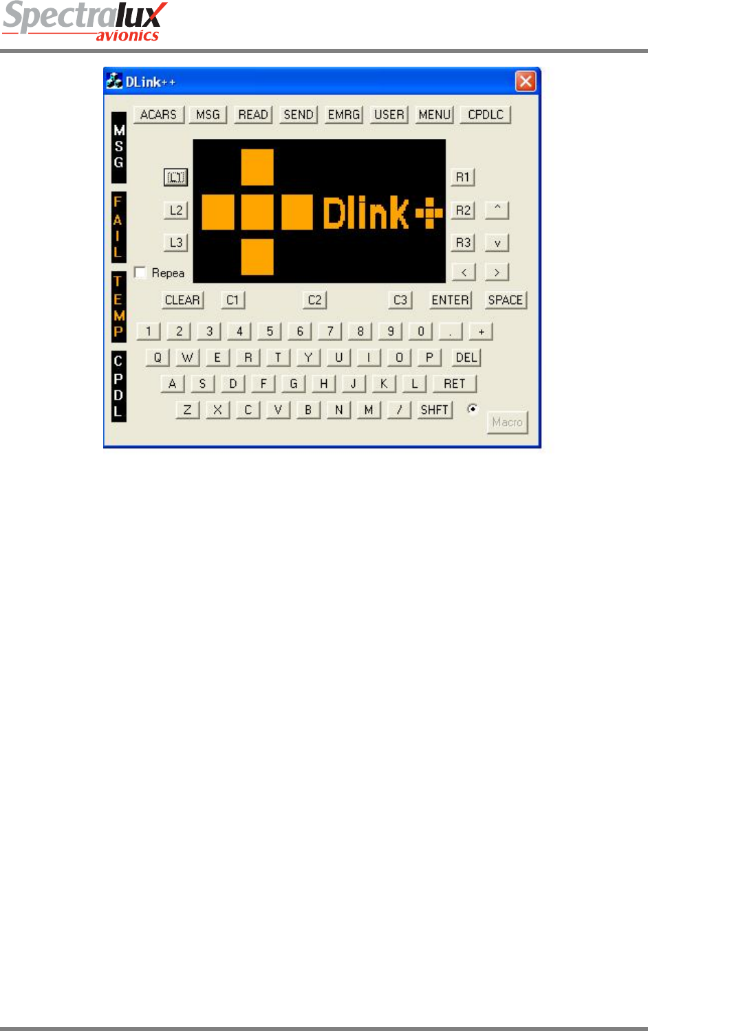
• Power up the Dlink+ w/CPDLC. Allow 10 seconds before trying to load the configuration. If none
have been loaded, the Dlink+ w/CPDLC should show its splash screen:
INST-14114-1
Dlink+ w/CPDLC Installation Manual
Document Number: INST-14114-1 Rev. - Page 12 of 25
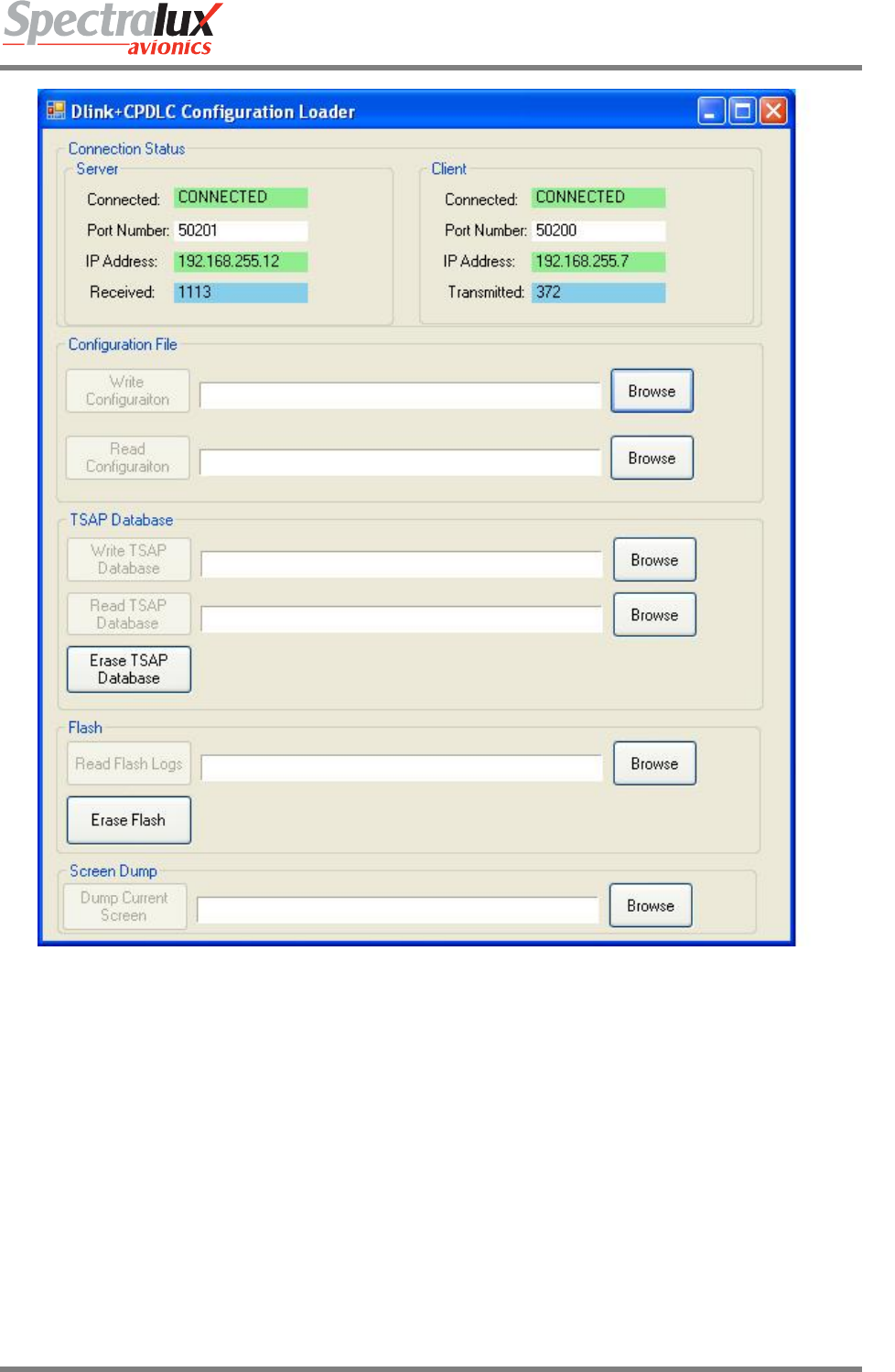
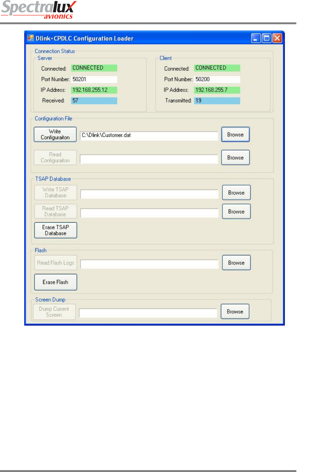
• Connect a Laptop PC containing the ConfigurationLoader software to the Ethernet connector.
• Load the provided test or customer database as follows. Start theConfigurationLoader software.
INST-14114-1
Dlink+ w/CPDLC Installation Manual
Document Number: INST-14114-1 Rev. - Page 13 of 25
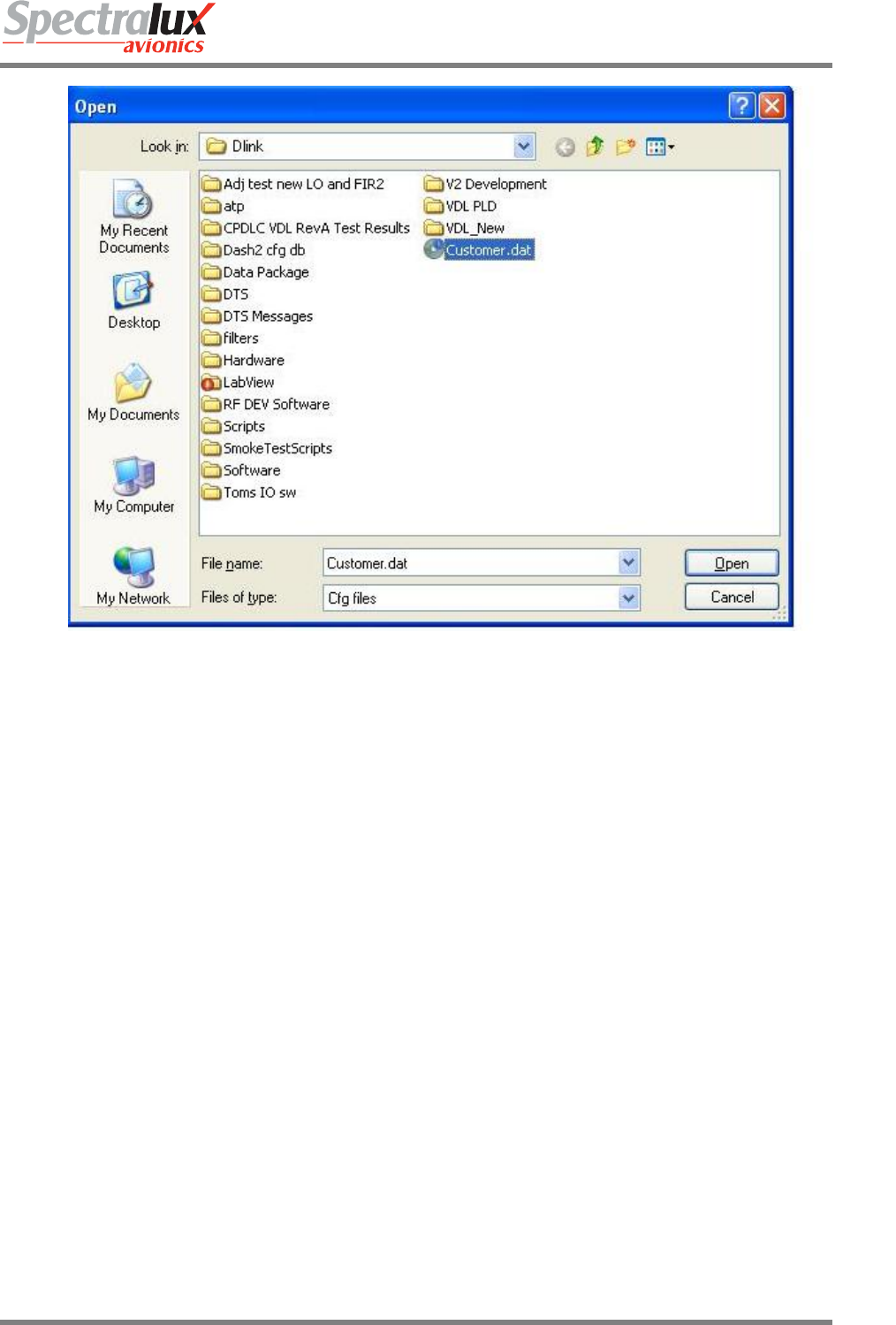
The configuration file is supplied by Spectralux and is customized for the installation. To select the
configuration click on Browse for Write Configuration and select the appropriate file.
INST-14114-1
Dlink+ w/CPDLC Installation Manual
Document Number: INST-14114-1 Rev. - Page 14 of 25
Select Open. To write the file, click on Write Configuration:
INST-14114-1
Dlink+ w/CPDLC Installation Manual
Document Number: INST-14114-1 Rev. - Page 15 of 25
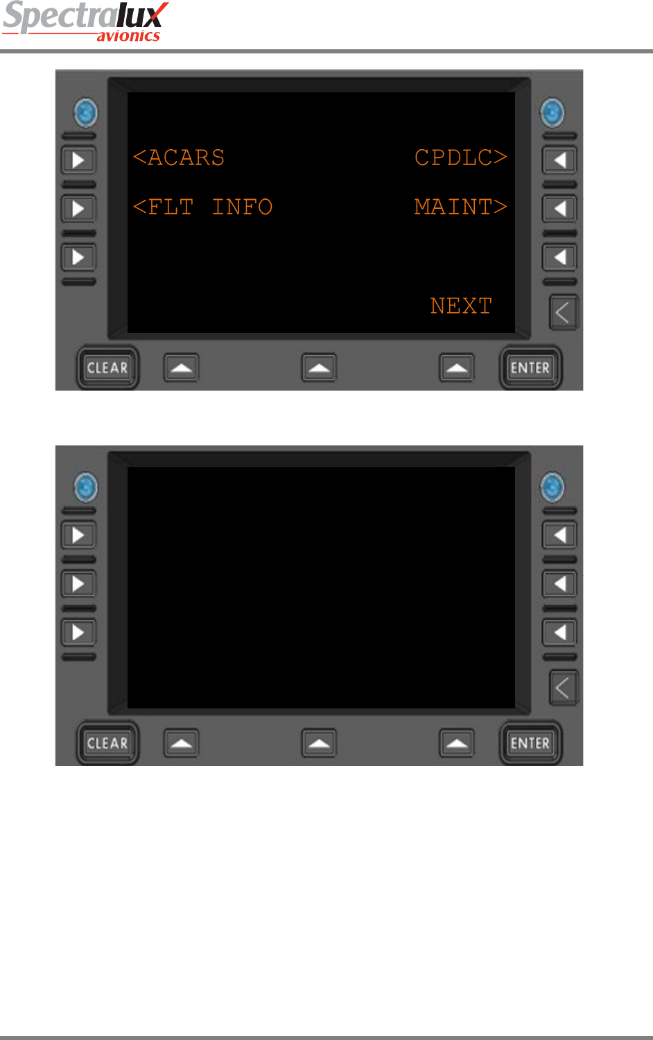
The Dlink+ w/CPDLC will reboot after loading of the configuration is complete and the screen should look
as follows:
INST-14114-1
Dlink+ w/CPDLC Installation Manual
Document Number: INST-14114-1 Rev. - Page 16 of 25
The Aircraft Specific Information must now be entered, start by selecting MAINT>:
MAINTENANCE MENU
<MONITOR CONFIG>
<SYS CNTRL SET UTC>
<RETURN FAIL STATUS>
NEXT
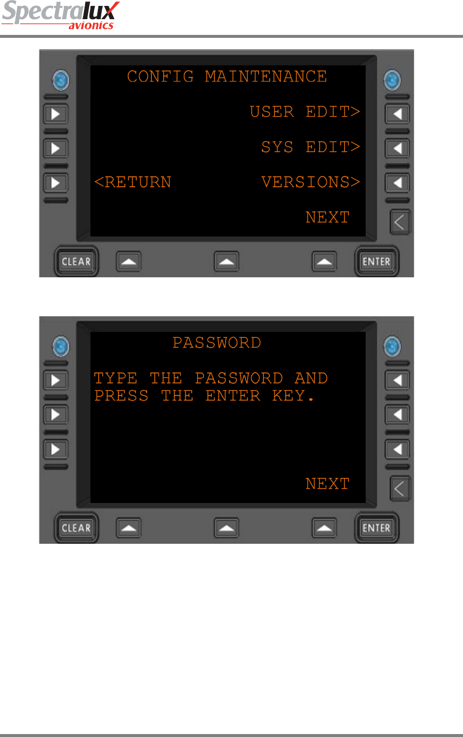
And then select CONFIG>:
INST-14114-1
Dlink+ w/CPDLC Installation Manual
Document Number: INST-14114-1 Rev. - Page 17 of 25
And then USER EDIT:
Enter the User Password and press ENTER:
INST-14114-1
Dlink+ w/CPDLC Installation Manual
Document Number: INST-14114-1 Rev. - Page 18 of 25
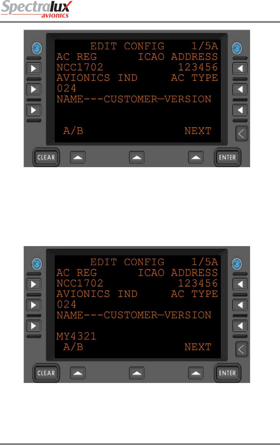
Now enter the above information.
NOTE: The AC REG (NCC1702), ICAO ADDRESS (123456) and AVIONICS IND (024) are default entries
in the database and are examples only.
Entered information first appears on the text entry line (just above A/B) and when all the text has been
entered for a particular item, select that item.
For example, to enter the AC REG (Tail number), enter the information:
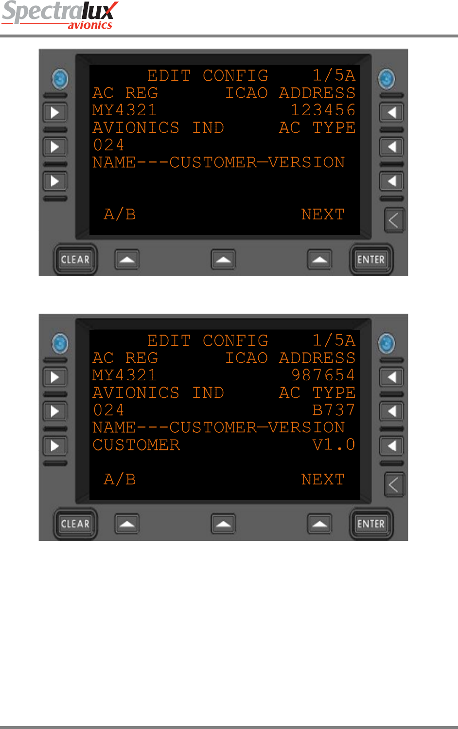
And then select AC REG:
INST-14114-1
Dlink+ w/CPDLC Installation Manual
Document Number: INST-14114-1 Rev. - Page 19 of 25
Continue in like process until all the information is entered:
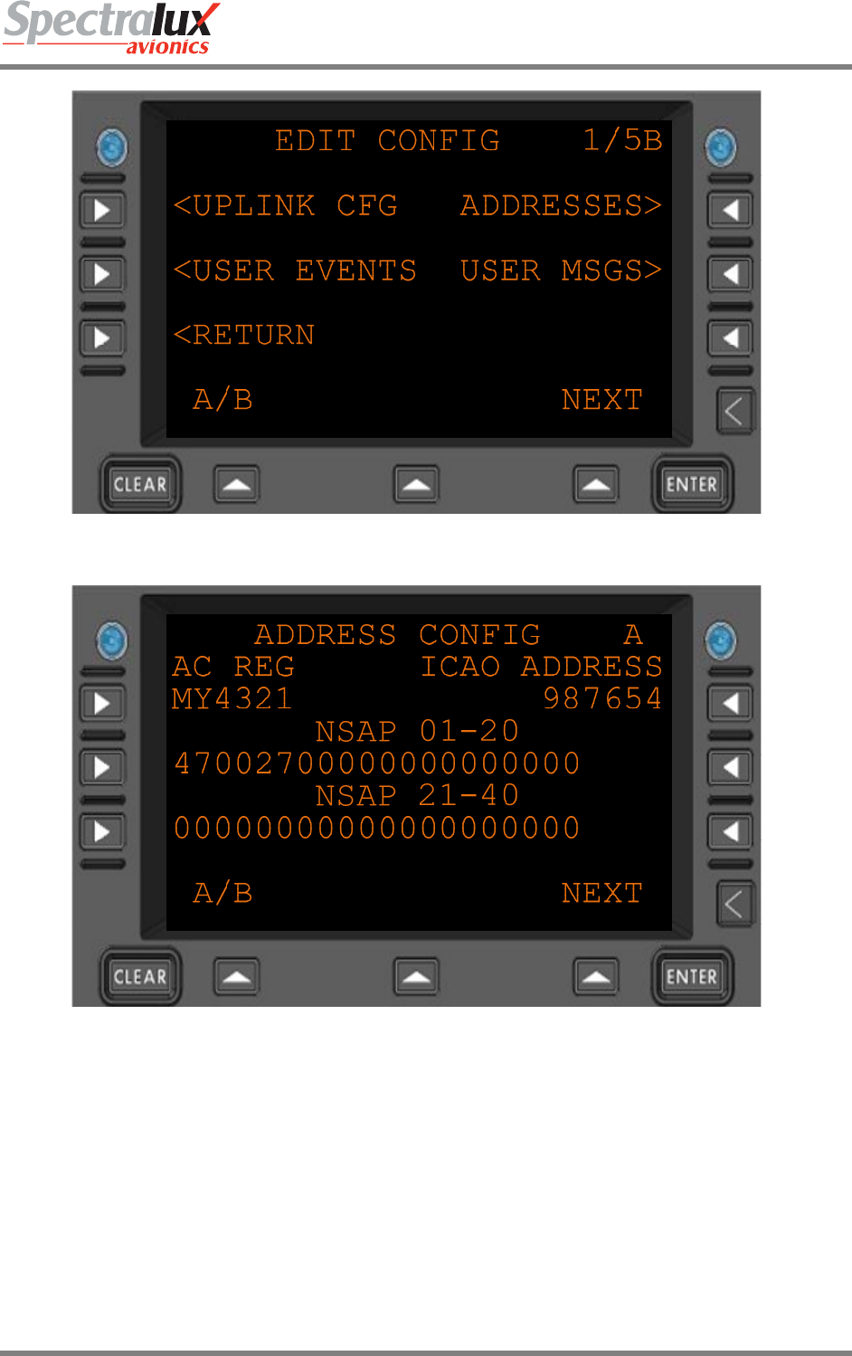
To enter the NSAP address & Agency code, press A/B:
INST-14114-1
Dlink+ w/CPDLC Installation Manual
Document Number: INST-14114-1 Rev. - Page 20 of 25
And the select ADDRESSES:
Enter the 40 digit NSAP number, first 20 digits on “NSAP 01-20” and last 20 digits on “NSAP 21-40”
Note: There is a default entry that needs to be overwritten.
INST-14114-1
Dlink+ w/CPDLC Installation Manual
Document Number: INST-14114-1 Rev. - Page 21 of 25
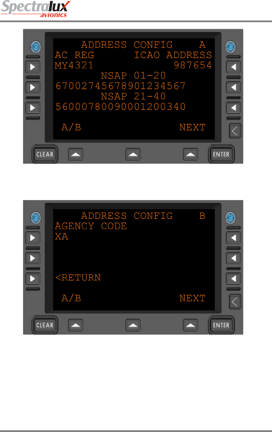
After entering the 2nd NSAP line, press A/B,
And enter the agency code:
Select RETURN:
INST-14114-1
Dlink+ w/CPDLC Installation Manual
Document Number: INST-14114-1 Rev. - Page 22 of 25
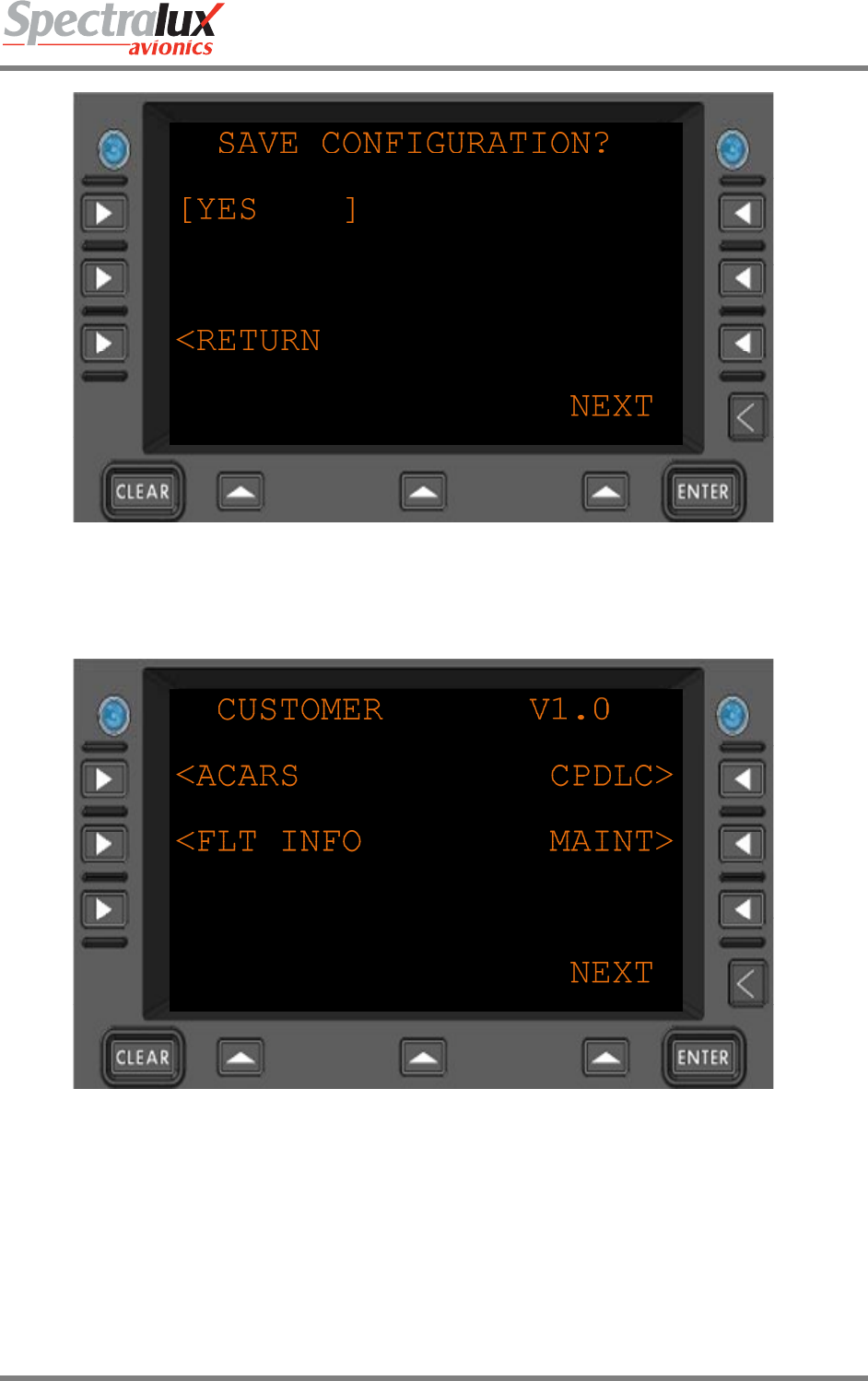
Make sure L1 says YES, and select <RETURN.
The Dlink+ w/CPDLC will reboot. Loading of the Configuration is now complete. The startup page will now
appear as follows:
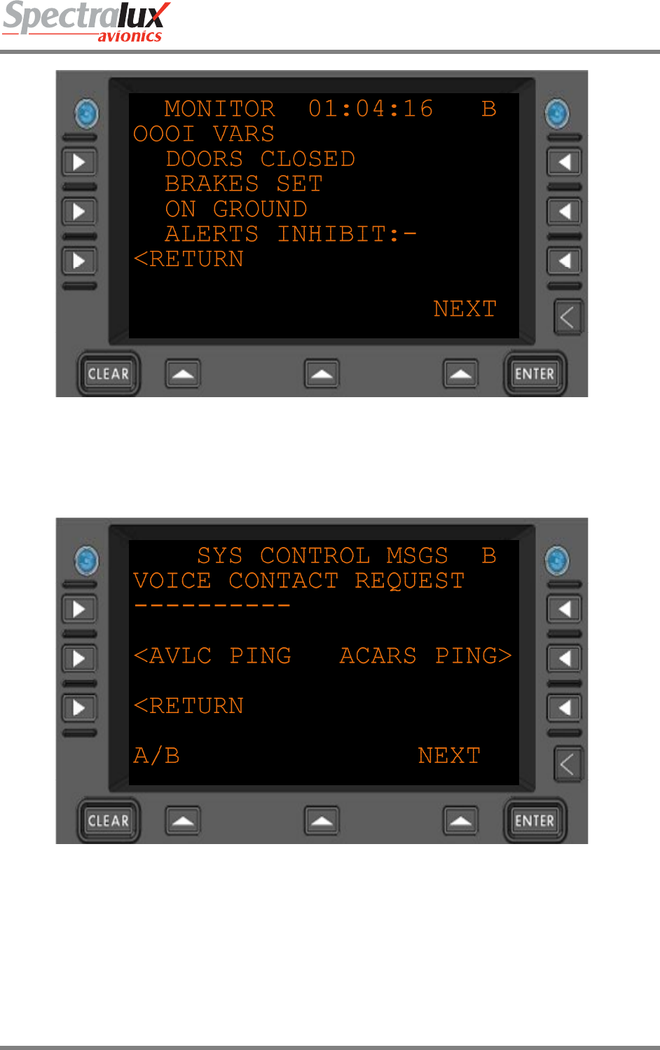
C. Test the installation by navigating on the Dlink+ w/CPDLC menus to the Maintenance menu
(MAINT>), select <MONITOR and finally A/B:
INST-14114-1
Dlink+ w/CPDLC Installation Manual
Document Number: INST-14114-1 Rev. - Page 23 of 25
Verify the OOOIs are operating by changing the state in maintenance mode on the aircraft and
verifying they change correctly in the menu.
To run a Ping Test and verify VHF Communication, navigate to the by pressing the USER key, select
<ACARS, select SYS CNTRL>, and press A/B:
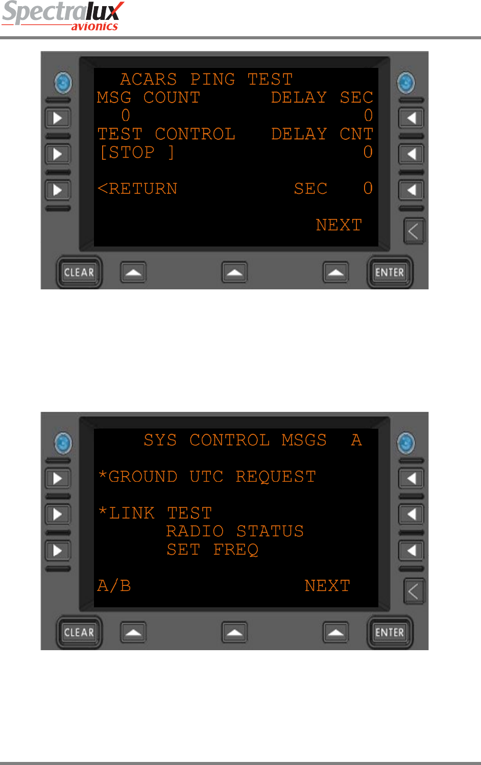
Then select ACARS PING:
INST-14114-1
Dlink+ w/CPDLC Installation Manual
Document Number: INST-14114-1 Rev. - Page 24 of 25
To send a single ping simply press LSK L2 to change the TEST CONTROL to GO. It will send a
message and then change to WAIT until the response is received then go back to STOP. DELAY
CNT will count seconds until the response is received. AVG SEC will show the time it takes to
receive a response. If no response is received after the timeout period the TEST CONTROL will
display FAIL. To send several messages change MSG COUNT to the number of messages. After all
messages have been sent AVG SEC will display the average response time.
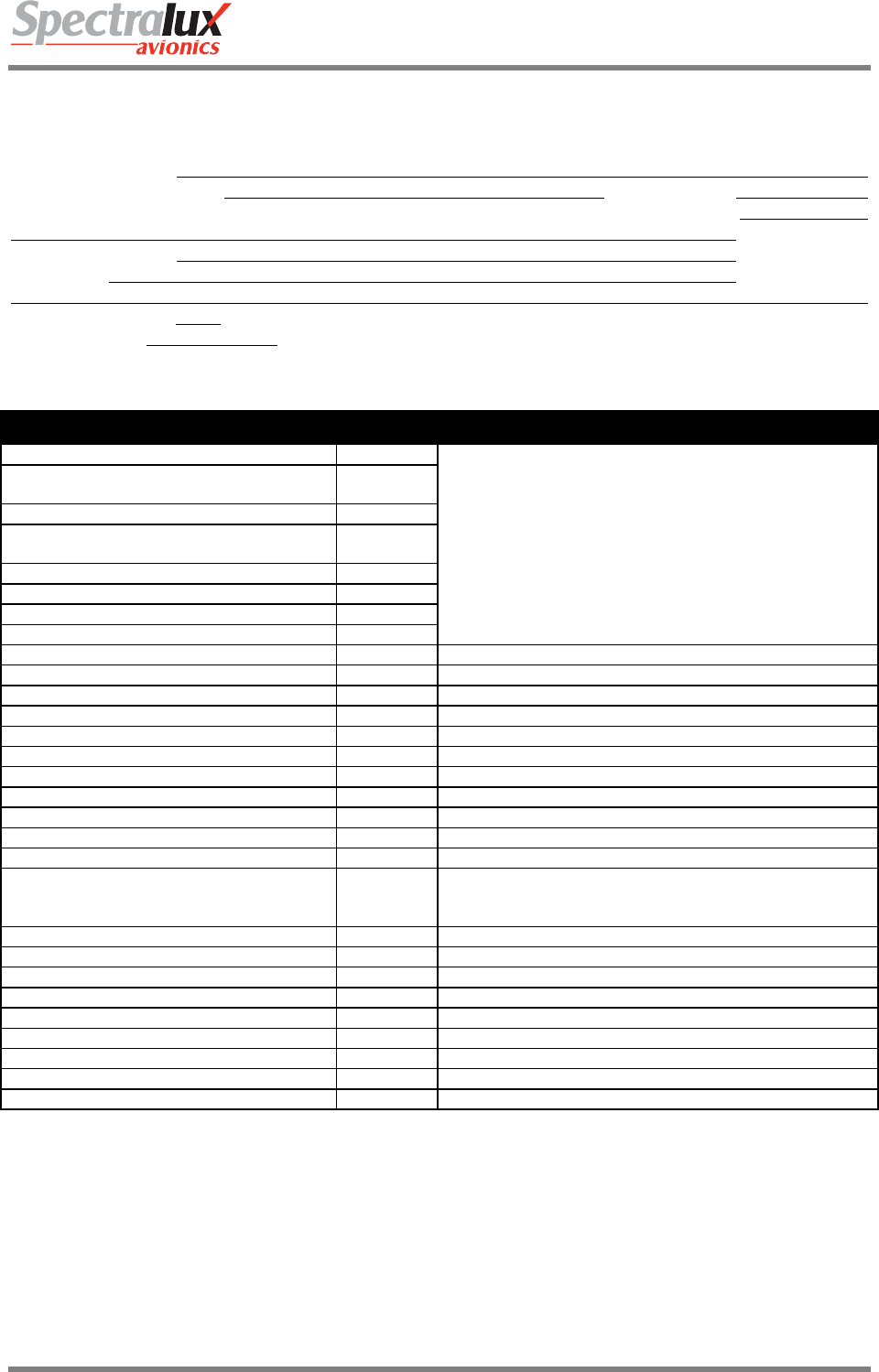
Select RETURN:
The *LINK TEST key will send a link test message.
Use the main Maintenance menu (press the USER key, select MAINT>, select <MONITOR) to
display the radio status to see if the message has been received. It is better to use a ping test to
verify the link.
INST-14114-1
Dlink+ w/CPDLC Installation Manual
Document Number: INST-14114-1 Rev. - Page 25 of 25
Appendix A – 14114-1-XX Environmental Qualification Form
NOMENCLATURE: Integrated Control Display/Communication Management/VHF Data Link Radio
TYPE/MODEL/PART NO: 14114-1-XX TSO NUMBER: C113, C160
MANUFACUTERER’S SPECIFICATION AND/OR OTHER APPLICABLE SPECIFICATION:
SRS-14114-1, System Requirements Specification
MANUFACTURER: Spectralux Avionics
ADDRESS: 12335 134th Court NE
Redmond, Washington 98052
REVISION DO-160: Rev E
DATE TESTED: 6/10/10 – 8/26/11
CONDITIONS SECTION DESCRIPTION OF TESTS CONDUCTED
Temperature and Altitude 4.0 Equipment Tested to Category A1
40,000 ft maximum operational altitude
Ground Survival Low Temperature and
Short-Time Operating Low Temperature 4.5.1
Operating Low Temperature 4.5.2
Ground Survival High Temperature and
Short-Time Operating High Temperature 4.5.3
Operating High Temperature 4.5.4
Altitude 4.6.1
Decompression 4.6.2
Overpressure 4.6.3
Temperature Variation 5.0 Equipment Tested to Category B
Humidity 6.0 Equipment Tested to Category A
Operational Shock and Crash Safety 7.0 Equipment Tested to Category B
Vibration 8.0 Equipment Tested to Category S, Curve B.
Explosion 9.0 Equipment Identified as Category X. No test performed.
Waterproofness 10.0 Equipment Identified as Category X. No test performed.
Fluids Susceptibility 11.0 Equipment Identified as Category X. No test performed.
Sand and Dust 12.0 Equipment Identified as Category X. No test performed.
Fungus 13.0 Equipment Identified as Category X. No test performed.
Salt Spray 14.0 Equipment Identified as Category X. No test performed.
Magnetic Effect 15.0 Equipment Tested to Category Z
Power Input 16.0 Equipment Tested to Category Z with Category A power
interruptions (200 ms). Not for connection to emergency
power.
Voltage Spike 17.0 Equipment Tested to Category A
Audio Frequency Susceptibility 18.0 Equipment Tested to Category Z
Induced Signal Susceptibility 19.0 Equipment Tested to Category ZC
Radio Frequency Susceptibility 20.0 Equipment Tested to Category TT
Radio Frequency Emissions 21.0 Equipment Tested to Category MM
Lightning Induced Transient Susceptibility 22.0 Equipment Tested to Category A2XX
Lightning Direct Effects 23.0 Equipment Identified as Category X. No test performed.
Icing 24.0 Equipment Identified as Category X. No test performed.
Electrostatic Discharge 25.0 Equipment Tested to Category A