Spotwave Wireless SPOTCELL0011 Spotcell 612 User Manual 612 ROW 040623 backup
Spotwave Wireless Ltd. Spotcell 612 612 ROW 040623 backup
UserManual.wiki
>
Spotwave Wireless
>
SPOTCELL0011 User Manual
>
User guide
Contents
1.
Quick install guide
2.
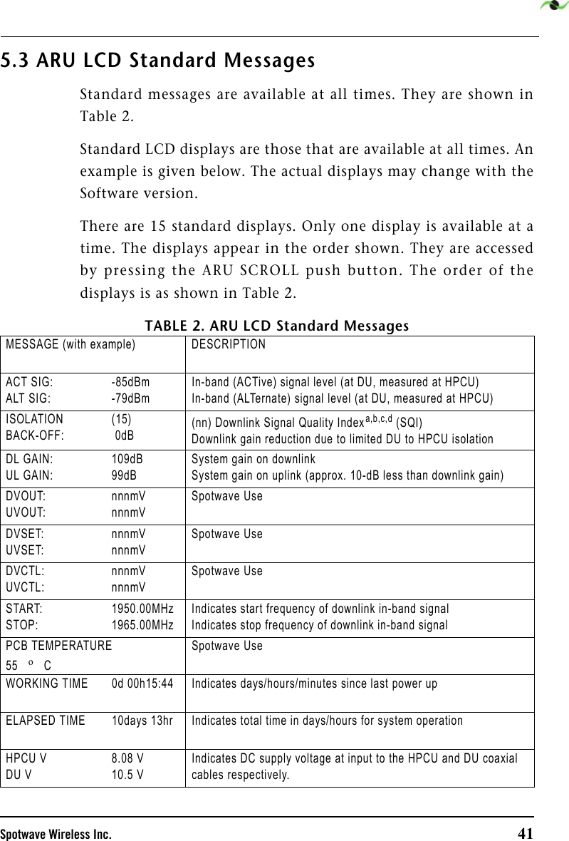
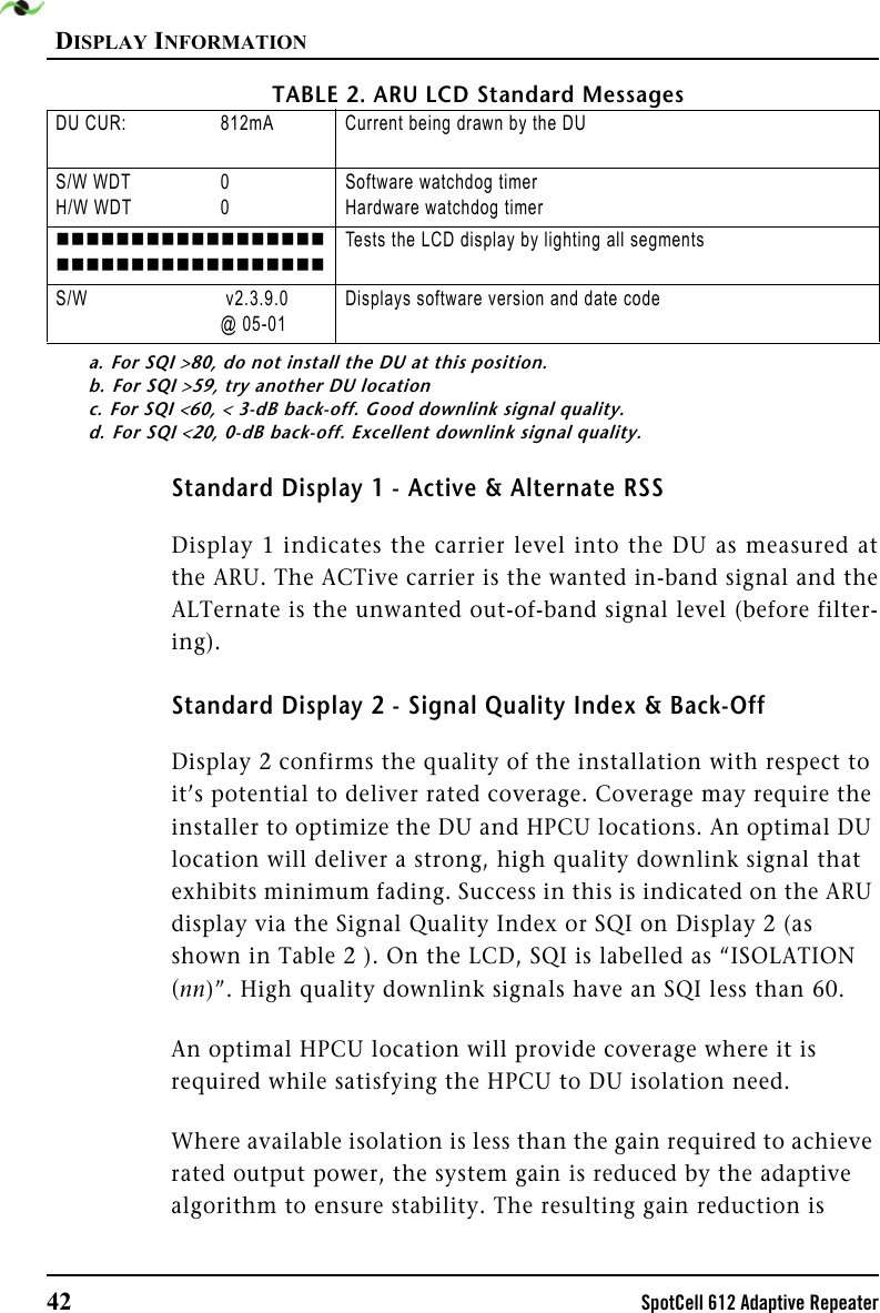
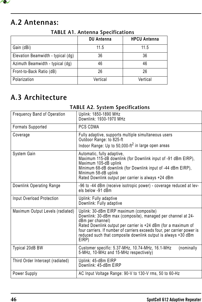
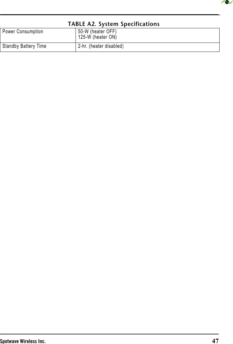
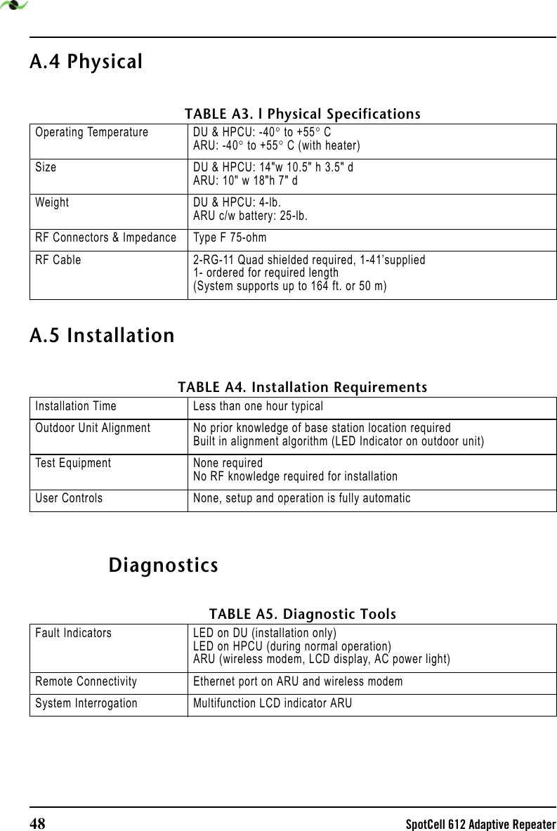
User guide
User guide
Navigation menu
Upload a User Manual
Namespaces
Wiki Guide
HTML
PDF
Info
Views
User Manual
Discussion / Help
Navigation