Spotwave Wireless SPOTCELL0011 Spotcell 612 User Manual 612 ROW 040623 backup
Spotwave Wireless Ltd. Spotcell 612 612 ROW 040623 backup
Contents
- 1. Quick install guide
- 2. User guide
User guide
Spotwave Wireless Inc. i
Technical Support
The SpotCell
TM
serial number must be available to authorize
technical support and/or to establish a return authorization for
defective units. The serial number is located on the back of the
High Power Coverage Unit (HPCU), Adaptive Repeater Unit (ARU)
and Donor Unit (DU), as well as the box in which they were
delivered. Support information may be obtained by accessing the
Spotwave Wireless Inc. website at www.spotwave.com. To contact
support by telephone, call your local Spotwave vendor, or if you
are
unable to do so, call Spotwave Wireless at 1-877-610-9586.
Important Safety Information
Warning!
For your safety, beware of power lines and ensure
appropriate separation distances, and safety measures, are
maintained at all times during the SpotCell equipment
installation. If equipment supplied by others is to be used during
installation or mounting, follow all equipment manufacturer’s
instructions to ensure injury is avoided.
If you are installing the SpotCell near high voltage power lines,
or in any way are not sure about a safe installation, do not
attempt to install it yourself. Call a professional installer for
help.
The DU and HPCU of the SpotCell are low power transmitters. As
with a cell phone antenna, avoid unneccessary contact with the
front of the units after installed. Mount the units in a location
where people will not approach within 1 meter of the front of the
DU or HPCU.

SUPPORT, SAFETY AND WARRANTY
ii SpotCell 612 Adaptive Repeater
Limited Warranty and Limitation of Warranty
1. What is Covered and for How Long?
Spotwave Wireless Inc. (“Spotwave”) warrants to the original Purchaser that the
Spotwave SpotCell System (the “System”) is free from defects in material and
workmanship under normal use and service for a period of 12 months from the
date of shipment from Spotwave (the “Limited Warranty Period”).
2. What is Not Covered?
This Limited Warranty is conditioned upon proper use of the System by the
Purchaser. This Limited Warranty does not cover (and will become null and void
in the event of): (a) defects or damage resulting from accident, misuse, abuse,
neglect, unusual physical, electrical or electromechanical stress, modification of
the System or any part thereof, or cosmetic damage; (b) removal, alteration or
defacing of the serial number or other identifying marks on the System; (c) all
plastic surfaces and other externally exposed components that are scratched or
damaged due to normal use; (d) malfunctions resulting from the use of the System
in conjunction with accessories, products or (ancillary) or peripheral equipment
not provided by Spotwave; or (e) defects or damage from unauthorized or
improper testing, operation, maintenance, installation, servicing or adjustment of
the System. Any repairs or replacements provided by Spotwave outside of the
Limited Warranty Period (including repairs to or replacement after the end of the
Warranty Period), or in excess of the services provided during the Limited
Warranty Period, will subject to Spotwave's then prevailing rates.
3. What are Spotwave's Obligations and how do you make a claim?
During the Limited Warranty Period, Spotwave will repair or replace, at
Spotwave's sole option, without charge to Purchaser, any defective component of
the System, provided that the System is returned promptly upon discovery of the
defect and during the Limited Warranty Period. To obtain service, Systems must
be returned to an authorized service facility in the original packaging or
packaging adequate for shipping, accompanied by Purchaser's sales receipt or
comparable substitute proof of sale showing the date of purchase and the serial
number of the System. A valid RMA is required prior to any return.
To locate your nearest authorized service facility, call Spotwave
Customer Service at 1-877-610-9586
.
Spotwave may, at Spotwave's sole option, use rebuilt, reconditioned, or new parts
or components when repairing any System or replace a System with a rebuilt,
reconditioned or new System. Repaired Systems will be warranted for a period
equal to the remainder of the original Limited Warranty Period for the original
System or for 90 days, whichever is longer. All replaced parts, components, boards
or equipment shall become the property of Spotwave. If Spotwave determines that
any System is not covered by this Limited Warranty, Purchaser must pay the costs
for all parts, shipping, and labor charges for the repair or return of such System.
4. What are the Limits on Spotwave's Liability?

Spotwave Wireless Inc. iii
EXCEPT FOR THE WARRANTY IN PARAGRAPH 1, THE SYSTEMS AND ANY
ASSOCIATED SERVICES ARE PROVIDED BY SPOTWAVE ON AS 'AS IS' BASIS AND
THERE ARE NO OTHER REPRESENTATIONS, WARRANTIES OR
CONDITIONS,EXPRESS OR IMPLIED, WRITTEN OR ORAL, ARISING BY STATUTE,
OPERATION OF LAW, COURSE OF DEALING, USAGE OF TRADE OR OTHERWISE,
REGARDING THEM OR ANY OTHER PRODUCT OR SERVICE PROVIDED
HEREUNDER OR IN CONNECTION HEREWITH BY SPOTWAVE. SPOTWAVE
DISCLAIMS ANY IMPLIED WARRANTIES OR CONDITIONS OF DURABILITY,
MERCHANT ABILITY, MERCHANTABLE QUALITY, SATISFACTORY QUALITY,
NON-INFRINGEMENT OR FITNESS FOR A PARTICULAR PURPOSE. SPOTWAVE
DOES NOT REPRESENT OR WARRANT THAT THE SYSTEMS WILL MEET ANY OR
ALL OF PURCHASERS' PARTICULAR REQUIREMENTS, THAT THE SYSTEMS WILL
OPERATE ERROR-FREE OR UNINTERRUPTED OR THAT ALL ERRORS OR DEFECTS
IN THE SYSTEMS CAN BE FOUND TO BE CORRECTED. System performance is
dependant upon the performance and availability of services or technology
provided by third parties and Spotwave is not responsible for service continuity
and reliability, reception, or other performance related limitations associated
with use of the Systems. NO AGREEMENTS VARYING OR EXTENDING THE TERMS
OF THIS LIMITED WARRANTY WILL BE BINDING ON SPOTWAVE UNLESS IN
WRITING AND SIGNED BY AN AUTHORIZED SIGNING OFFICER OF SPOTWAVE
THIS LIMITED WARRANTY SHALL NOT EXTEND TO ANYONE OTHER THAN THE
ORIGINAL PURCHASER OF THE SYSTEM. SPOTWAVE'S MAXIMUM AGGREGATE
LIABILITY TO PURCHASER SHALL NOT EXCEED THE AMOUNTS PAID BY
PURCHASER FOR THE SYSTEM GIVING RISE TO THE CLAIM. SPOTWAVE SHALL
NOT BE LIABLE FOR ANY SPECIAL, INCIDENTAL, CONSEQUENTIAL, INDIRECT
OR SIMILAR DAMAGES, LOSS OF USE, DATA OR PROFITS, DAMAGES TO
PURCHASER'S PROPERTY, OR INJURY TO PURCHASER OR OTHERS ARISING OUT
OF THE USE, MISUSE OR INABILITY TO USE ANY SYSTEM, WHETHER OR NOT
SUCH DAMAGE ARISES OUT OF CONTRACT OR TORT (INCLUDING WITHOUT
LIMITATION, NEGLIGENCE) OR CLAIMS BY A THIRD PARTY, EVEN IF SPOTWAVE
HAS BEEN ADVISED OF SUCH DAMAGES OR THEY ARE FORESEEABLE
5. This Limited Warranty
allocates risk between Purchaser and
Spotwave, and the Spotwave System pricing reflects this allocation of
risk and the limitations of liability contained in this Limited Warranty.
The agents, employees, distributors, dealers or representative of
Spotwave are not authorized to make modifications to this Limited
Warranty, or make additional warranties binding on Spotwave.
Accordingly, additional statements such as advertising or presentations,
whether oral or written, do not constitute warranties by Spotwave and
should not be relied upon.

SUPPORT, SAFETY AND WARRANTY
iv SpotCell 612 Adaptive Repeater
Ownership and Risk of Loss
6. Who Owns the rights in the System?
The System is protected by Canadian, US and international copyright law and
other intellectual property protection laws and treaties. Purchaser acknowledges
that Spotwave and its licensors are the owner of all intellectual property,
including, without limitation, patents and copyright,
relating to the System and the trademarks used in association with the System.
Purchaser agrees that it will not (and will not attempt to) modify, prepare
derivative works of, reverse engineer, decompile, disassemble, or other attempt to
derive the source code of any software contained within the System.
7. Who bears the Risk of Loss?
Risk of loss for the System passes to Purchaser upon the delivery to Purchaser or to
a carrier for shipment, which ever is earlier. Title to the Systems (excluding any
software) will pass upon payment in full for the Systems. Title to any software
shall always remain with Spotwave or its licensors. As security for payment,
Purchaser grants to Spotwave a purchase money security interest in the Systems
(together with any proceeds, including insurance proceeds) and agrees that a copy
of this letter of agreement or any other appropriate document may be registered
as required to perfect the security interest granted. Systems may be resold by
Purchaser in normal course of business, but until paid for in full, Purchaser will
not pledge or otherwise encumber the Systems. Purchaser agrees to immediately
report to Spotwave, any seizure or attachment of the Systems by creditors; (ii) any
petition in bankruptcy, insolvency, receivership or similar proceedings filed by,
or against Purchaser; or (iii) any arrangement, composition or similar agreement
for the benefit of creditors. Systems held for Purchaser by Spotwave are at
Purchaser's sole risk and expense.
OTHER TERMS:
8. What terms govern our relationship?
These terms and any software license or warranty documentation accompanying
the Systems constitute the complete and exclusive statement of the terms and
conditions between us regarding the Systems and cannot be altered, amended or
modified except in writing executed by Spotwave. This letter of agreement and
any disputes arising hereunder shall be governed by and interpreted in
accordance with the laws of the Province of Ontario, Canada. The United Nations
Convention on Contracts for the International Sale of Goods and any legislation
implementing such Convention, if otherwise applicable is expressly excluded.
Any terms and conditions of any purchase order or other instrument issued by
Purchaser which are in addition to or inconsistent with the terms and conditions
of this letter of agreement shall not be binding and shall not apply, even if
accepted by Spotwave.

Spotwave Wireless Inc. v
Manual Disclaimer
Product specifications, pricing, packaging, technical support and information
(“Specifications”) and all claims, features, representations, and/or comparisons
provided are correct to the best of our knowledge of the date of publication, but
may contain errors or omissions and are subject to change without notice.
INFORMATION IS PROVIDED BY SPOTWAVE WIRELESS INC. ON AN “AS IS”
BASIS, WITHOUT ANY OTHER WARRANTIES OR CONDITIONS, EXPRESS OR
IMPLIED, INCLUDING, BUT NOT LIMITED TO, WARRANTIES OF
MERCHANTABLE QUALITY, SATISFACTORY QUALITY, MERCHANTABILITY OR
FITNESS FOR A PARTICULAR PURPOSE, OR THOSE ARISING BY LAW, STATUTE,
USAGE OF TRADE, COURSE OF DEALING OR OTHERWISE. THE ENTIRE RISK AS
TO THE RESULTS OF THE INFORMATION PROVIDED IS ASSUMED BY YOU. WE
SHALL HAVE NO LIABILITY TO YOU OR ANY OTHER PERSON OR ENTITY FOR
ANY INDIRECT, INCIDENTAL, SPECIAL, OR CONSEQUENTIAL DAMAGES
WHATSOEVER, INCLUDING, BUT NOT LIMITED TO, LOSS OF REVENUE OR
PROFIT, LOST OR DAMAGED DATA OR OTHER COMMERCIAL OR ECONOMIC
LOSS, EVEN IF WE HAVE BEEN ADVISED OF THE POSSIBILITY OF SUCH
DAMAGES, OR THEY ARE FORESEEABLE. WE ARE ALSO NOT RESPONSIBLE FOR
CLAIMS BY A THIRD PARTY. OUR MAXIMUM AGGREGATE LIABILITY TO YOU
AND THAT OF OUR DEALERS AND SUPPLIERS SHALL NOT EXCEED FORTY
DOLLARS. SOME STATES/COUNTRIES DO NOT ALLOW THE EXCLUSION OR
LIMITATION OF LIABILITY FOR CONSEQUENTIAL OR INCIDENTAL DAMAGES,
SO THE ABOVE LIMITATIONS MAY NOT APPLY TO YOU.
All product, font and company names are trademarks or registered trademarks of
their respective owners.

SUPPORT, SAFETY AND WARRANTY
vi SpotCell 612 Adaptive Repeater

SPOTCELLTM 612 ADAPTIVE REPEATER
Spotwave Wireless Inc. vii
Table of Contents
Chapter 1 Introduction 1
This Manual 1
Installer Qualifications 1
Product Overview 3
Chapter 2 Getting Started 5
Required Equipment and Material 5
Unpacking and Inspecting 8
Chapter 3 Performance Considerations 9
Overview 9
Performance Factors 13
Approved Installation Methods 16
Geographic Coordinates and Azimuth 17
Chapter 4 Installation 21
Safety 21
ARU Installation 23
HPCU Installation 27
Alignment 30
Dominant Alignment 32
Non-Dominant Alignment 34
Installation Completion 36
Chapter 5 Display Information 37
DU & HPCU LED Indicators 37
ARU LCD Action Messages 39
ARU LCD Standard Messages 41
SpotCell 612 Specifications 45
Compliance 45
Antennas: 46
Architecture 46
Physical
48
Installation
48

viii SpotCell 612 Adaptive Repeater
Spotwave Wireless Inc. 1
Chapter 1 – Introduction
1.1 This Manual
The contents of this manual complements the Quick Install
Guide, and provides specific details that may be referred to if
necessary during installation of the SpotCell™ system.
1.2 Installer Qualifications
1.2.1 Work Near High-Tension Power Lines
Warning!
If your installation requires the SpotCell adaptive
repeater to be located near high voltage power lines, such as on
or near an electrical power pole or tower, the installation of the
Donor Unit (DU), Coverage Unit (HPCU) and associated coaxial
cables and ground wire must be done by a trained high-tension

INTRODUCTION
2SpotCell 612 Adaptive Repeater
power-line professional. This professional must be knowledgeable
and experienced in high voltage electrical safety, including safe
separation distances and safety measures.
The trained professional shall maintain appropriate separation
distances from high voltage lines and follow applicable safety
measures at all times during the installation.
1.2.2 Connection of AC Power
The connection of AC power to the SpotCell Adaptive Repeater
Unit (ARU) shall be done only by a fully qualified, licensed
electrician in full accordance with local and national code
requirements.
1.2.3 Repeater Set-up and Alignment
The SpotCell 612 adaptive repeater installation does not require
any specialized radio frequency technical knowledge. It requires
no special RF installation tools. For some installations the
following may be required:
GPS satellite receiver (most current models are suitable)
A good quality magnetic compass
To complete the work quickly and efficiently it is recommended
that the installer have completed the Spotwave Wireless installer
training program, and be Level I Certified.
Spotwave Wireless Inc. 3
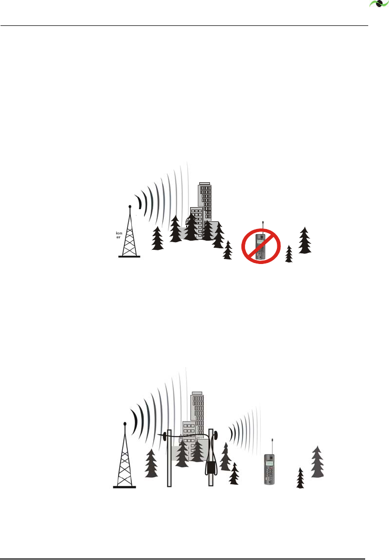
1.3 Product Overview
The purpose of the SpotCell 612 is to enable personal wireless
communications in specific locations within a wireless service
area where cell phones do not work, or works poorly, for example
along a highway right-of-way where it dips down into a valley,
coulee or draw, or the signal is obstructed by buildings or trees.
Figure 1.1 Base station signal does not reach wireless subscriber
The SpotCell system receives signals from a wireless base station
and re-transmits them to areas where cell phones do not work
well due to obstructions or the remoteness of the location.
Figure 1.2 SpotCell improves wireless communications
The SpotCell™ 612 is a fully adaptive repeater that provides
4

INTRODUCTION
4SpotCell 612 Adaptive Repeater
band-selective, on-frequency, out-of-building (and for specific
applications - in-building) coverage in the PCS Band. It uses
proprietary, patent-pending, adaptive techniques that allow
SpotCell to be installed and operated without engineering
intervention or support.

Spotwave Wireless Inc. 5
Chapter 2 – Getting Started
2.1 Required Equipment and Material
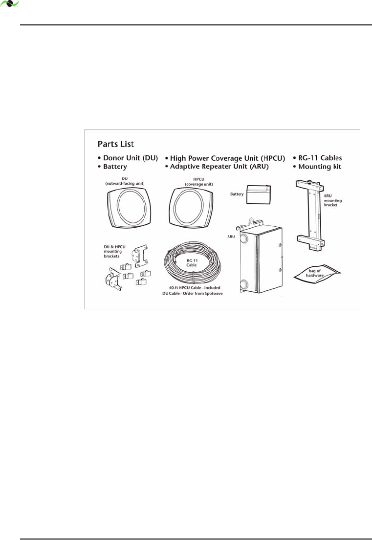
2.1.1 SpotCell 612 Adaptive Repeater Standard Kit
The SpotCell standard kit is shipped in 3 boxes containing:
1-Donor Unit (DU) - this unit communicates with the service
provider’s (Carrier’s) existing mobile communications
network.
1-HP Coverage Unit (HPCU) - this unit extends coverage to a
nearby area where service is required.
1-Adaptive Repeater Unit (ARU) - this unit provides DC power
to the DU and HPCU, automatically and adaptively controls
gain so as to provide consistent coverage and protect the
spectrum by guaranteeing protection from instability,
provides a user interface for set-up and trouble shooting and
a wireless network operations interface.
1-HPCU to ARU RG-11 Coaxial Cable (40-ft)
1-stand-by battery c/w thermal isolator
GETTING STARTED
6SpotCell 612 Adaptive Repeater
Mounting Kit which includes:
1- ARU mounting bracket
2- antenna pipe mount kits (for DU and HPCU)
1- bag of hardware
Figure 2.1 below shows the SpotCell 612 system components.
Figure 2.1 SpotCell 612 Adaptive Repeater Parts List
2.1.2 Required Additional Material - Order from Spotwave
1-DU to ARU RG-11 Coaxial Cable - this cable is ordered for
the required length ad application. Cable suitable for conduit
installation is stocked. Inquire about the availability of aerial
and direct bury cables.

Spotwave Wireless Inc. 7
2.1.3 Required Additional Material - Supplied by Installation
Contractor
DU and HPCU support structures (poles or towers)
Stub pole for mounting ARU (where not installed on the
HPCU support pole)
All grounding network material (ground rods, ground wire,
ground lugs, ground wire clamps, etc.)
Conduit, ducts or poly-pipe as specified by the Carrier
Antenna support pipes and hardware, these pipes attach to
the antenna support poles, the DU and HPCU units attach to
these pipes using the supplied pipe mounts.
AC electrical service material (wire, conduit and disconnect
switch, and if required - meter, meter socket, service wire,
transformer, etc.)

GETTING STARTED
8SpotCell 612 Adaptive Repeater
2.2 Unpacking and Inspecting
Physically inspect the box for shipping damage before unpacking
the SpotCell.
1. Remove the SpotCell components from the box.
2.
Remove all packing material from the Donor Unit (DU) and
the Coverage Unit (HPCU) and ARU (Adaptive Repeater Unit).
Save the packaging in case the SpotCell is ever stored or
shipped to SpotWave for service.
3.
Check the contents of the package to make sure you have
received everything ordered and verify that the mounting kit
contains all the listed parts.
4.
Check the DU, HPCU and ARU for shipping damage.

Spotwave Wireless Inc. 9
Chapter 3 – Performance Considerations
3.1 Overview
The DU is typically attached to a utility pole or tower, a non-
penetrating roof mount support pipe, or the exterior wall of a
building.
The HPCU is typically attached to a second utility pole or tower,
a second non-penetrating roof mount support pipe, or the
exterior wall of a building. For inside building coverage the
HPCU may be wall or ceiling mounted.
This document focuses on applications using two utility poles.
The use of two utility poles is typical for a ‘right-of-way’ (ROW)
application. The goal of a ROW application is typically that of
PERFORMANCE CONSIDERATIONS
10 SpotCell 612 Adaptive Repeater
adding coverage to street and highway routes where coverage was
previously not provided, such as down in a dip in the road for
example.
There are 4 elements to an installation, 1) infrastructure
installation, 2) HPCU and ARU installation, 3) DU alignment and
system optimization and 4) installation completion.
Because utility pole installations often do not have AC power
available at the pole, the infrastructure work is usually greater
than for a roof-top application. Where this is the case, it would
be best to have the infrastructure work complete before the
SpotCell repeater installation begins. This permits the repeater
installers to complete the installation in one visit and in
minimum time.
However for locations where the repeater location is uncertain,
the performance at two or more locations may wish to be checked
and compared before any installation work starts.
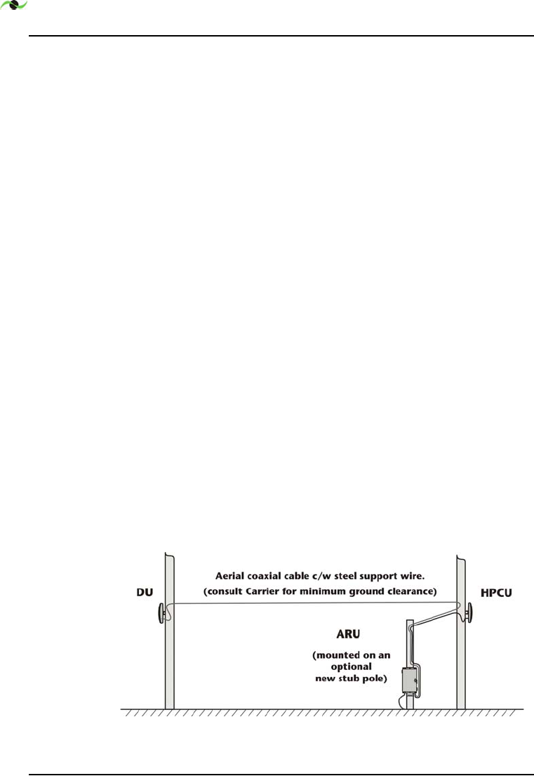
3.1.1 Aerial Cable vs. Buried Cable
For some installations aerial coaxial cable c/w a steel support wire
will be used. The steel support wire is attached to the pole using
Carrier recommended hardware and methods. The aerial span is
Figure 3.1 Aerial Installation c/w ARU Stub Pole
Spotwave Wireless Inc. 11
installed such that the Carrier specified ground clearance and
power line separation distances are strictly observed. Figure 3.1
shows an aerial cable installation c/w the ARU mounted on an
optional new stub pole.
Alternatively the ARU would be mounted on the HPCU support
pole where permitted by the utility pole owner.
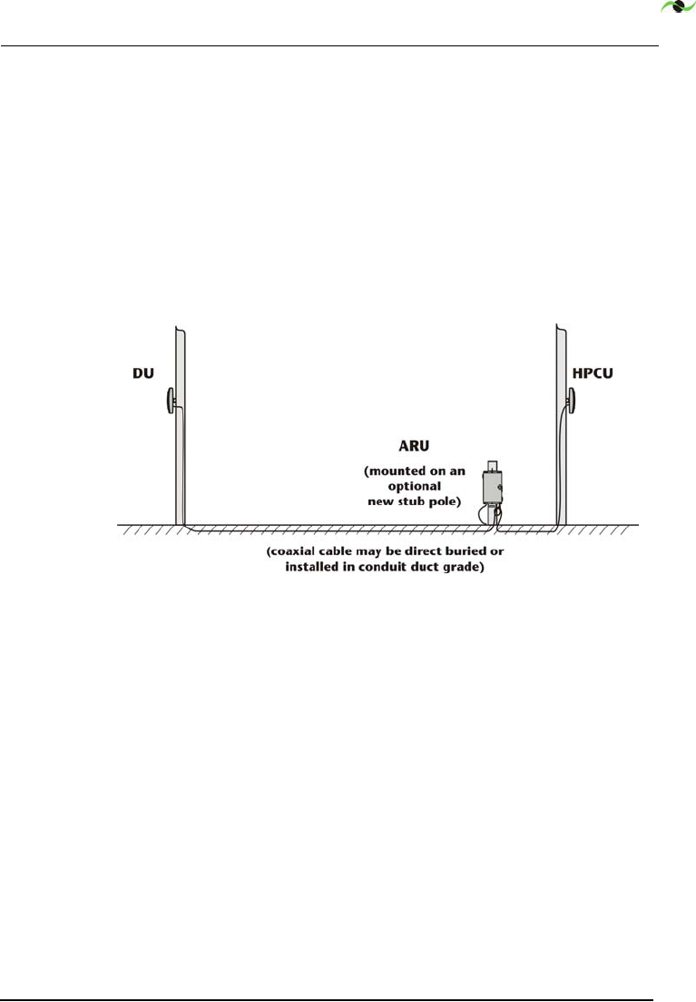
Other installations will use direct bury type coaxial cable - see
Figure 3.2.
Figure 3.2 Buried cable c/w ARU Stub Pole
Said cable may be direct buried or installed in duct below grade.
Consult the Carrier with respect to the requirements for the
specific installation location.
For the vertical runs of the coaxial cable and ground wire, the
Carrier may require one or both to be strapped directly to the
pole, or installed in conduit attached to the pole. The means and
method for attaching the cable to the pole, or the conduit to the
pole may also be specifically specified by the Carrier.
.

PERFORMANCE CONSIDERATIONS
12 SpotCell 612 Adaptive Repeater
3.1.2 ROW Infrastructure Installation
Includes:
1. Site acquisition.
2.
New pole installation (if required).
3.
New electrical service installation (if required).
4.
Grounding network preparation.
5.
DU and HPCU support pipe installation.
6.
Installation of conduit or duct for the coaxial cable (as
required).

Spotwave Wireless Inc. 13
3.2 Performance Factors
The following should be considered when installing a SpotCell
system.
3.2.1 Mounting Height
Locating the DU as high as possible often provides a better
connection to the service provider’s PCS basestation. A DU
mounting height above 18-ft above ground level (AGL) is
recommended.
Locating the HPCU at a high height also usually improves
coverage. The standard ARU to HPCU cable is 40-ft in length.
The ARU is located on or adjacent to the HPCU support pole.
In addition, increasing the DU to HPCU separation distance will
increase isolation - this may also increase the coverage.
3.2.2 Signal Strength
The SpotCell system brings signals from an area of adequate
coverage to an area with poor or non-existent coverage. It is the
DU which captures a good signal, and the HPCU that provides
the signal to the area with poor cell phone coverage.
Note:
For maximum coverage, a receive signal strength (RSS) of -
85-dBm at the DU or higher is preferred. Although, not all
installations require maximum coverage a RSS below -90-dBm is
NOT recommended.
3.2.3 Unwanted Obstacles
General placement of the DU and HPCU must be in unobstructed
areas. Neither the front of the DU or the front of the HPCU
should be directly obscured by buildings or trees. Large metal

PERFORMANCE CONSIDERATIONS
14 SpotCell 612 Adaptive Repeater
apparatus such as transformers on utility poles or HVAC
equipment found on building rooftops may also degrade
performance.
3.2.4 Power Source
To reduce cost the SC612 repeater should be close to a suitable
AC power source. If this is not practical, install a solar power
system.
3.2.5 Azimuth Differential
Although ideally the DU and HPCU should face in opposite
directions, i.e. a back to back configuration and azimuth
differential of 180-dg. an azimuth difference between the two
units of 90-dg or greater is recommended.
3.2.6 Wanted Obstacles
For a pole mounted SC612 repeater, the opportunity of selecting
pole locations in order to take advantage of a physical obstacle
between the DU and HPCU to improve RF isolation is not often
practical.
For a roof-top located SC612 this is possible and should be done.
The two units should be located on opposite exterior walls of the
building, or opposite exterior walls on the roof-top penthouse.
For the two utility pole application with no obstacle between the
poles, separate the poles 85-ft or more apart. The standard DU to
ARU cable is 164-ft in length.
Walls constructed of dense materials (concrete, brick or metal
provide high isolation. However, such walls may also be a source
of reflections and antenna pattern degradation. When locating
the DU and HPCU avoid placement where such adjacent walls are
significantly within the view of the antenna.

Spotwave Wireless Inc. 15
3.2.7 Aerial or Direct Bury Cable
Standard cable for the SC612 is RG-11. When ordering from
Spotwave be sure to inquire about the cable installation type
preferred.
Note:
Some Carriers prefer that cable installed below grade be
placed within a conduit, duct or poly-pipe to simplify replacement
and protect against ground freezing.
Aerial cable requires an integrated steel support wire for hanging
the cable between utility poles. Alternatively cable may be
installed in steel supported duct.
‘Filled’ cable is needed for direct burial below grade, i.e. not in
conduit, duct or poly-pipe. Such cable is flooded with a
petroleum compound or a dry-fill powder for protection from
water ingress.
The supply of suitable aerial and direct bury cables is limited.
Call Spotwave for availability.

PERFORMANCE CONSIDERATIONS
16 SpotCell 612 Adaptive Repeater
3.3 Approved Installation Methods
When planning an installation, consult the Carrier for approved
installation methods. When arranging for the use of utility poles
the Carrier and utility company will have developed a set of
approved methods. Such methods may define:
1. Procedures for contacting and coordinating work with local
Carrier or Utility personnel.
1. Minimum separation distances between SpotCell equipment
and high voltage electrical lines.
2.
Acceptable locations for new support poles and procedures
for approval and installation.
3.
Grounding network materials and installation methods -
ground wire, ground rod, lightning arrestor and bonding.
4.
Pole attachment methods for coaxial cables, ground wire and
SpotCell equipment (DU, HPCU and ARU), and approved
methods for aerial and direct buried cable installation.
5.
AC power equipment, solar power equipment and installation
methods.

Spotwave Wireless Inc. 17
3.4 Geographic Coordinates and Azimuth
The Carrier will specify the existing utility poles to be used. The
general location may be defined using town names and street
addresses, but the specific location is defined using geographic
coordinates. GPS accuracy is to a resolution of 30-ft. Pole
numbers will also usually be provided.
Geographic coordinates are needed as not all streets or roads are
named or numbered, and poles do not have addresses. Also the
Carrier’s engineering database uses geographic coordinates.
Latitude and longitude coordinates have 3 parts - Latitude,
Longitude and Datum. UTM coordinates have 4 parts - Northing,
Easting, UTM Zone and Datum. UTM coordinates permit fast map
location.
3.4.1 Map Datum
The earth is not a perfect sphere. The map datum is a means for
adjusting for this. For the USA and Canada 2 map datums are
used NAD27 and NAD82. The default datum for the world is
WGS84. For the USA and Canada WGS84 and NAD83 are usually
identical.
When using coordinates to find your location on a map you need
to have your GPS receiver set to the datum that is printed on the
map that you are using.
If the Carrier provides the coordinates in a datum different from
the map datum, your GPS receiver may be used to translate them
for you. This is done by entering the coordinates as a waypoint
with the GPS configured for the datum which the carrier uses,
then reconfiguring the GPS to the map datum and then recalling
the waypoint from memory. The waypoint will then show the
coordinates as per the map datum.

PERFORMANCE CONSIDERATIONS
18 SpotCell 612 Adaptive Repeater
3.4.2 Lat./Long - Degrees Minutes Seconds Format
Lat.: 40
o
37’ 54.9”, Long: 104
o
56’ 15.2”, Datum: NAD27, or
Lat.: 40.37549, Long: -104.56152, Datum: NAD27
Both of the above formats are used. Disregard the Longitude sign.
3.4.3 Lat./Long - Decimal Degrees Format
Lat.: 40.63192, Long: 104.93756, Datum: NAD27
This is the same location as above but in decimal degree format.
3.4.4 UTM Coordinates
UTMs are sometimes referred to as military grid references. The
following is the same location as given above:
Northing: 4497.687, Easting: 505.300, Zone:13, Datum: NAD27
Northing is the distance in kilometers from the equator, Easting
is the distance in kilometers from the East boundary of Zone 13.
Topographic maps are divided up into 1-km squares with
Northings and Eastings labelled. Using a scale of 2-cm = 1-km any
location can be quickly and accurately plotted on the map. This
is difficult using Latitude and Longitude.
3.4.5 Topographic Map and GPS Receiver
Prior to visiting a site it is recommended that you acquire the
applicable 1:50,000 scale topographic map and become familiar
with setting your GPS receiver to NAD27 and NAD83 Datums.

Spotwave Wireless Inc. 19
3.4.6 Azimuth (Bearing)
The azimuth of a DU or HPCU is the direction that it points. It is
given in degrees East (clockwise) from True North. True North is
typically several degrees different from Magnetic North. This is
called magnetic declination. It varies by location and changes a
small amount each year.
The Carrier typically gives you the Azimuth in degrees relative to
True North. This doesn’t help if you want to align the HPCU
using your magnetic compass. and you don’t know what the
declination is. However there is a method of determining the
declination using your GPS receiver.
If you know the coordinates for the basestation that the Carrier
wants the DU to be served by and the coordinates for the DU
location, your GPS will tell you the magnetic azimuth that the
DU should be aimed at, if your GPS is set for magnetic azimuths.
On this setting it automatically takes into account the magnetic
declination. So, if the Carrier specifies the azimuth for the DU to
be 90-dg relative to true North (i.e. aimed due East) but your GPS
gives you an azimuth of 100-dg magnetic. Then the declination is
10-dg.
So if the Carrier specifies that the HPCU is to be aimed at 270-dg
(i.e. due West) then you will use you compass to aim the HPCU at
an azimuth of 280-dg magnetic.
When using a compass be sure not to be close to large steel
objects or a false alignment will result.

PERFORMANCE CONSIDERATIONS
20 SpotCell 612 Adaptive Repeater

Spotwave Wireless Inc. 21
Chapter 4 – Installation
This section is for typical for a typical ‘right-of-way’ application,
where the DU and HPCU are to be mounted on separate utility
poles, where the Carrier has specified the required azimuth and
mounting heights, and where the required infrastructure work is
already complete.
4.1 Safety
4.1.1 Work Site Safety
Warning!
Before any work is started at the work site, take note of
overhead and underground power lines, and any other dangers at
the work site. Ensure safe separation distances from power lines,
and safe working practices are followed at all times. When
working near roads wear safety vests, white coveralls, and orange
hardhats; also place warning signs, flags and traffic cones to warn
motorists. Work facing traffic whenever possible and make use of
a b a r r i e r v e h i c l e f o r a d d e d p r o t e c t i o n .

INSTALLATION
22 SpotCell 612 Adaptive Repeater
Caution! If you are installing the SpotCell near high voltage power
lines, or in any way are not sure about a safe installation, do not
attempt to install it yourself. Call a professional installer, with the
appropiate training and skills, for help.
4.1.2 RF Safety Statement
The SpotCell 612 repeater uses RF energy and complies with 47
CFR, Part 1.1310 , Radiofrequency Exposure Limits for fixed
installations, pursuant to 47 CFR, Part 24.52 of the FCC rules and
regulation for PCS equipment and 47 CFR, Part 1.1310(b).
Mount the intentional radiators, the DU and the HPCU, in
locations where the general public will not approach within 1
meter (3.28-ft) of the location of either.
Caution! Occupational workers, such as electrical utility personnel
and repeater service personnel, who are in a transient in front of
the DU or HPCU should not be within 4-cm (1.6-in) of the front of
the operating intentional radiator for more than 4.6-minutes.
Spotwave Wireless Inc. 23
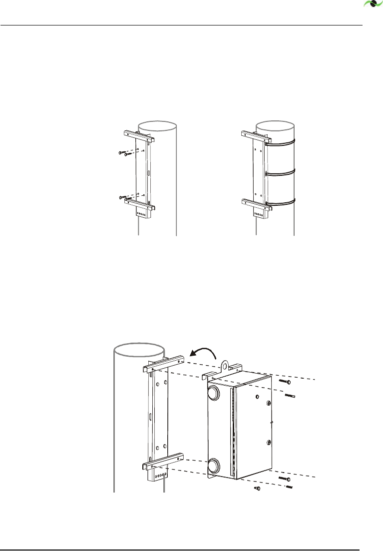
4.2 ARU Installation
1. Mount the ARU hanger bracket on the HPCU support pole, or
a near alternative. Consult the Carrier with respect to specific
requirements. The bracket can be attached with four screws or
three steel bands - see Figure 4.1.
Figure 4.1 ARU Mounting Bracket Options (screw mount or steel
band mount)
2.
If necessary use a rope attached to the ARU eye bolt to lift
and hold it while fastening it to the mounting bracket with
the provided 4 bolts, nuts and washers as shown in Figure
4.2.
Figure 4.2 ARU Mounting
INSTALLATION
24 SpotCell 612 Adaptive Repeater
Caution! Connection of AC power to the ARU shall be done by a
fully qualified licensed electrician (Steps 3 and 4).
3.
Before connecting the AC power to the ARU ensure that the
AC power source is de-energized and the disconnect switch
feeding the ARU power circuit and cable is locked OFF.
4.
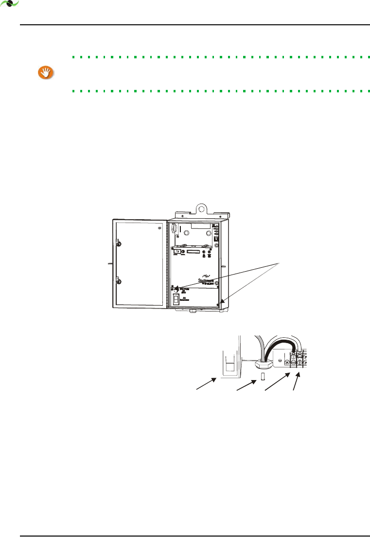
Open the ARU front door using an Allen wrench and ensure
that the ARU circuit breaker is in the open or OFF position.
Loosen the two front panel screws and remove the lower
front panel - see Figure 4.3.
Figure 4.3 ARU Interior Panel and AC Power Connection
Loosen the dome nut on the weather proof 3/4-in conduit
fitting at the bottom of the ARU cabinet. Route the AC
electrical supply conduit and wire through the fitting.
Tighten the dome nut until mild resistance is felt then
tighten 1/4-turn additional for conduit (1/2-turn additional
for cable not in conduit).
panel
screws
circuit
breaker
g
lug
round live
(black)
neutral
(white)
Spotwave Wireless Inc. 25
Connect the live (normally black) wire to the left side of the
connector block, the neutral (normally white) wire to the
right side of the connector block, and the ground (normally
green) wire to the ground stud on the bottom of the ARU
cabinet using a suitable ground lug.
Follow all local electrical code requirements.
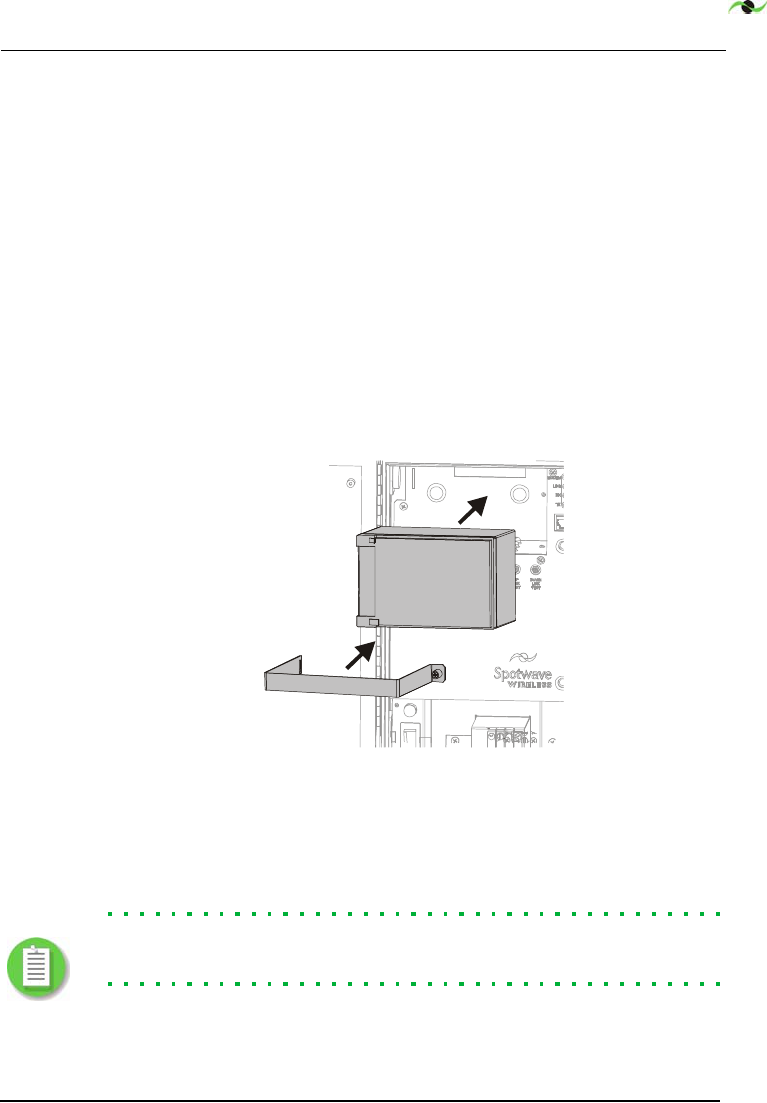
5.
Loosen the back-up battery clip screws and remove the
battery clip - see Figure 4.4.
Connect the red wire to the battery positive (+) terminal and
the black wire to the negative (-) terminal. Place the battery
on the tray in the ARU cabinet and place the thermal
insulator behind the battery.
Figure 4.4 Battery installation
Replace and fasten the battery clip. Replace the ARU panel
and fasten the panel screws.
Note:
A fully discharged battery takes 6-hr to charge in the
ARU. Batteries are shipped charged.
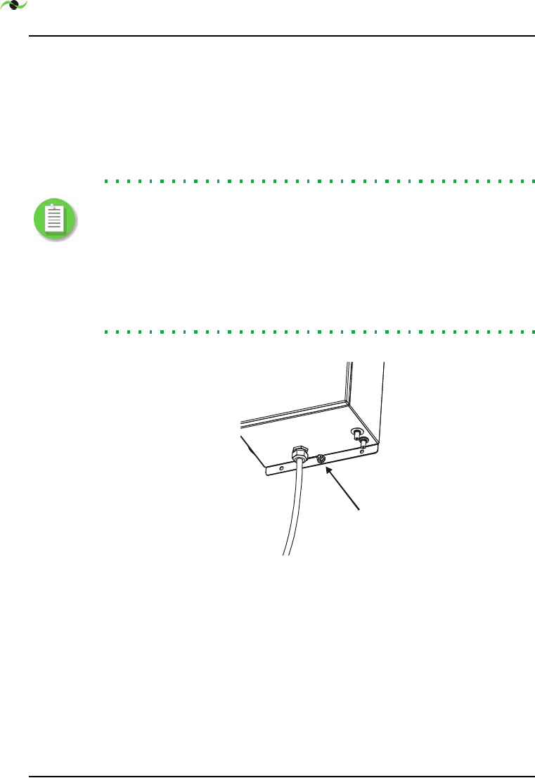
6.
Bond the external ARU cabinet ground stud to the HPCU
support pole ground network if the ARU and HPCU are
collocated on the same pole, i.e. not collocated but
battery
battery clip
INSTALLATION
26 SpotCell 612 Adaptive Repeater
connected below grade by buried cable or cable in duct and
are less than 12-ft apart - see Figure 4.5. Use a suitable ground
lug.
Otherwise bond the ground wire to an ARU ground rod
installed at the base of the ARU support. For addition details -
see the Grounding Note below.
Note:
If the grounding infrastructure work was not done earlier,
contact the Carrier to confirm ground wire size and type, and the
grounding network requirements for both the HPCU and DU. In
general the minimum is #6-AWG bare copper ground wire bonded
to a 5/8-in x 10-ft copper clad ground rod c/w suitable ground
pipe clamp placed at or near the base of both the HPCU and DU
support poles. Mechanical protection of the ground wire may be
required. Ensure that local code requirements are met.
Figure 4.5 ARU Cabinet Ground Stud
external
ground
stud

Spotwave Wireless Inc. 27
4.3 HPCU Installation
1.
Fasten the HPCU mount to the HPCU mounting pipe at the
Carrier specified mounting height, using the provided clamps
- see Figure 4.6 (same mounting hardware for both the HPCU
and the DU).
Figure 4.6 HPCU and DU Pipe Mount
Using a magnetic compass orient the mounting bracket so
that when the HPCU is attached it will be aimed at the
Carrier specified azimuth. Provide for the angular difference
between True North and Magnetic North. When aimed
correctly tighten the pipe clamp.
2.
Fasten the HPCU to the pipe mount bracket using the
provided nuts and washers.
3.
Install the provided 40-ft RG-11 ARU to HPCU coaxial cable,
and supply and install the HPCU ground wire, as per the
Carrier specified requirements.
Note:
The maximum recommended HPCU cable length is 50-ft.
For some installations the coaxial cable and ground wire will
be strapped directly to the pole, for others it will be installed
in conduit attached to the pole. If the ground wire is inside a
metallic conduit then both ends of the conduit must be
bonded to the ground wire.
INSTALLATION
28 SpotCell 612 Adaptive Repeater
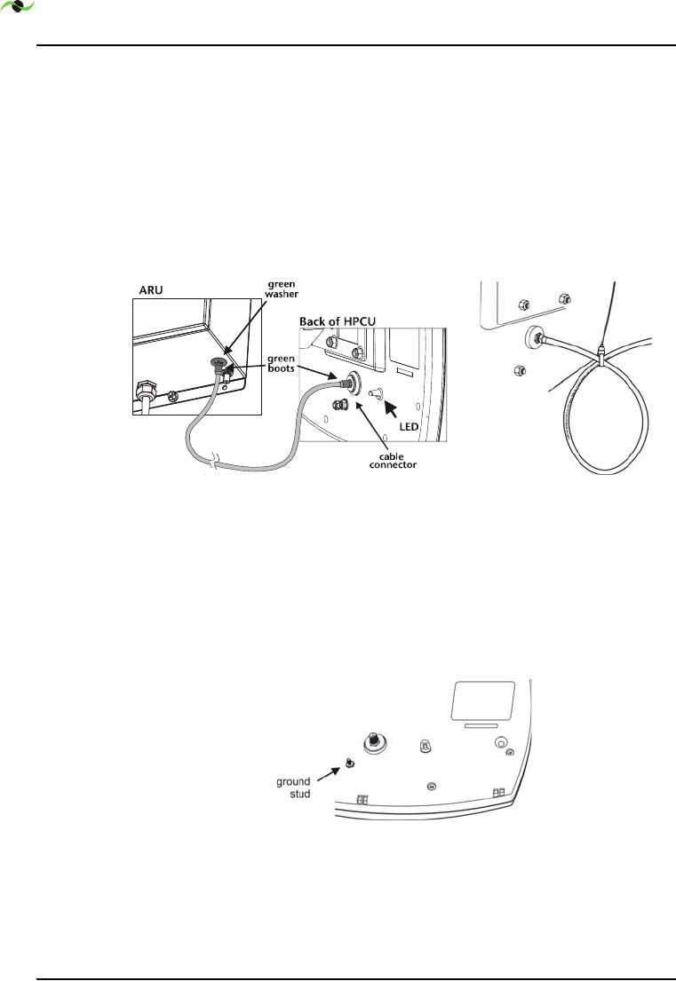
4.
Connect the HPCU coaxial cable (the 40-ft cable with green
boots) to the green RF port on the underside of the ARU
cabinet - see Figure 4.7.
A drip loop in the coaxial cable is needed if the cable at the
back of the HPCU does not slope down from the HPCU.
Maintain a minimum bend radius of 3-in. A drip loop is
shown on the right in Figure 4.7.
Figure 4.7 ARU to HPCU Cable and Drip Loop
Include slack for minor alignment adjustments. Use a wrench
to tighten all coax connectors 1/4 turn past finger tight.
5.
Bond the HPCU to ground using the installed ground wire.
Figure 4.8 Ground stud (HPCU and DU)

INSTALLATION
30 SpotCell 612 Adaptive Repeater
4.4 Alignment
4.4.1 Preparation
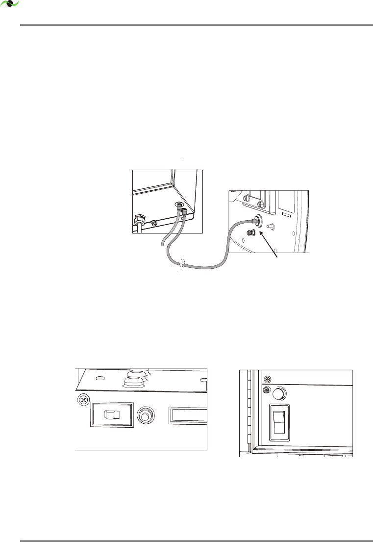
1. Temporarily connect the ARU to DU coaxial cable - see Figure
4.9. The DU support pole is typically over 80-ft from the
HPCU support pole. Connect one end of the provided 160-ft
RG-11 cable to the remaining RF port on the ARU, and the
other end to the back of the DU. During alignment testing
the DU will be handheld.
Figure 4.9 ARU to DU Coaxial Cable Connection
2.
Set the ARU Mode switch to INSTALL mode (right position -
opposite of ACTIVE). Energize the AC power cable feeding the
ARU, and set the ARU circuit breaker to the closed (ON)
position - see Figure 4.10.
Figure 4.10 ARU Mode Switch, Scroll Push button and Circuit
Breaker/Power Switch
The HPCU LED turns green and stays on as long as it has
power.
ARU
cable
connector
Back of DU
A
CTIVE SCROLL
PSU FUSE
2A
250V
AC
BREAKER

Spotwave Wireless Inc. 31
4.4.3 Alignment Overview
This work locates and aims the DU so that for maximum coverage
potential is provided. For some installations this work may also
result in a minor HPCU alignment change being made.
A bucket truck is recommended for lifting the DU and installer up
to the proposed DU location(s). Observe all appropriate safety
measures.
4.4.4 Coverage Potential
For maximum coverage potential, a receive signal strength (RSS)
of -85-dBm at the DU or better is needed. When the RSS is weak
DU to HPCU isolation is very important. The more the DU and
HPCU approach a back-to-back orientation and/or the further the
two units are apart, the greater the isolation and coverage
potential.
4.4.5 Alignment Options
If the Carrier has specified that the DL basestation signal that the
DU is to use will be a non-dominant signal (i.e. non-dominant PN
code), then skip Section 3.5 (Dominant Alignment) and jump to
Section 3.6 (Non-Dominant Alignment).
INSTALLATION
32 SpotCell 612 Adaptive Repeater
4.5 Dominant Alignment
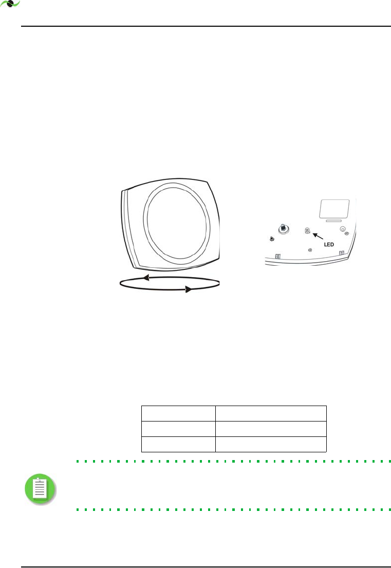
1.
R
OTATION
#1.
At the proposed DU mounting location and
height, hold the DU upright pointing away from your body.
Rotate it in a full circle - see Figure 4.11. A time of 20 seconds
is appropriate to complete the rotation. Ignore the DU LED
indication - see Figure 4.11.
If a full rotation is not practical rotate it within the
constraints allowed, but be sure to include the azimuth
specified by the Carrier for the DU.
Figure 4.11 DU Alignment Using LED Indicator
2.
R
OTATION
#2
. Repeat the rotation of the DU but now monitor
the LED - see Figure 4.11. Take note of the azimuths that
show a GREEN LED - there may be more than one range of
azimuths where the LED is GREEN.
Note:
For a dominant carrier the Carrier specified azimuth for
the DU will fall within the GREEN. If this is not the case jump to
Section 3.6, Non-Dominant Alignment.
Table 1. DU LED Indications
RED LED Unusable DU DL signal
YELLOW LED Usable DU DL signal
GREEN LED Better DU DL signal

Spotwave Wireless Inc. 33
3.
Have your assistant use the SCROLL button on the ARU to
access the ACT/ALT indication on the ARU LCD display, then
monitor the ACT signal level. The ACT reading is the wanted
downlink RSS in dBm.
4.
O
PTIMIZE
S
IGNAL
S
TRENGTH
.
Start by holding the DU at the
proposed mounting location and height, and aimed to receive
a GREEN LED indication. This alignment should roughly
approximate the carrier specified azimuth. Have your
assistant read out for you the ACT signal level while you fine
tune the aim of the DU so as to optimize the signal strength.
5.
O
PTIMIZE
C
OVERAGE
.
While holding the DU where the RSS is
maximum, have your assistant set the ARU Mode switch to
ACTIVE mode then SCROLL the ARU display to the
RSS/Coverage bar graph display as shown below. Carefully
adjust the aim of the DU to increase the number of coverage
bars.
Note:
Maximum coverage potential is indicated when 5 bars are
displayed on the Coverage bar graph (see left - lower display).
Coverage is proportional to both the RSS (the top bar graph
display) and the DU to HPCU isolation.
6.
HPCU and DU optimization. If maximum coverage cannot be
achieved by modest DU positioning adjustments alone, make
a modest adjustment to the HPCU orientation then repeat
steps 1 to 5. Limit the HPCU azimuth change to 15-dg,
maximum.
7.
Alternate DU mounting height and/or location. Return the
HPCU to the original position and try a higher or lower DU
mounting height then repeat steps 1 to 5. Do not work at
locations which are unsafe. Always maintain minimum power
line clearance distances.
8.
When an optimum DU position and alignment is determined,
attach the DU to its mounting pipe using the provided
hardware, then tighten the mounting bolts for both it and
the HPCU - while ensuring that both the DU and the HPCU
remains optimally aligned. Jump to Section 4.7.

INSTALLATION
34 SpotCell 612 Adaptive Repeater
4.6 Non-Dominant Alignment
1.
Have your assistant use the SCROLL button on the ARU to
access the ACT/ALT indication on the ARU LCD display, then
monitor the ACT signal level. The ACT reading is the wanted
downlink RSS in dBm.
2.
Using a magnetic compass identify an object several hundred
feet from the DU pole that is on the azimuth that the Carrier
has specified for the DU to be aligned at.
3.
While initially aiming the DU at the previously said
identified object and holding it at the proposed mounting
location and height, have your assistant read out for you the
ACT signal level while you fine tune the aim of the DU so as
to optimize the signal strength. Limit the DU azimuth
variance with respect to the Carrier specified azimuth to 15-
dg, maximum.
4.
While holding the DU where the RSS is maximum, have your
assistant set the ARU Mode switch to ACTIVE mode then
SCROLL the ARU display to the RSS/Coverage bar graph
display as shown below. Carefully adjust the aim of the DU to
increase the number of coverage bars.
Note:
Maximum coverage potential is indicated when 5 bars are
displayed on the Coverage bar graph (see left - lower display).
Coverage is proportional to both the RSS (the top bar graph
display) and the DU to HPCU isolation.
5.
If maximum coverage cannot be achieved by modest DU
positioning adjustments alone, make a modest adjustment to
the HPCU orientation then repeat steps 1 to 4. Limit the
HPCU azimuth change to 15-dg, maximum.
6.
Alternate DU mounting height and/or location. Return the
HPCU to the original position and try a higher or lower DU
mounting height then repeat steps 1 to 4. Do not work at
locations which are unsafe. Always maintain minimum power
line clearance distances.

Spotwave Wireless Inc. 35
7.
When an optimum DU position and alignment is determined,
attach the DU to its mounting pipe using the provided
hardware, then tighten the mounting bolts for both it and
the HPCU - while ensuring that both the DU and the HPCU
remains optimally aligned.
INSTALLATION
36 SpotCell 612 Adaptive Repeater
4.7 Installation Completion
1.
Install the RG-11 ARU to DU coaxial cable, as per the Carrier
specified requirements. This cable is typically 164-ft in
length. It is not in the SpotCell system kit. It is ordered from
Spotwave at the same time the system is ordered.
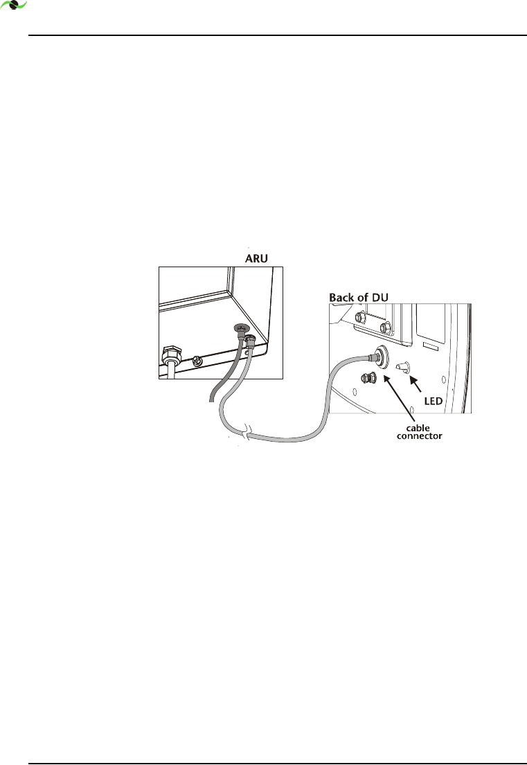
2.
Connect the DU end of the coaxial cable to the DU as shown
on the left in Figure 4.12. If the cable runs directly down the
pole from the DU a drip loop is not required. Connect the
ARU end of the ARU-DU cable to the remaining RF port on
the ARU.
Figure 4.12 ARU to DU Cable (the long cable)
Use a wrench to tighten all coax connectors 1/4 turn past
finger tight.
3.
Bond the DU to ground using the installed ground wire. At
the base of the DU pole the ground wire is bonded to the
ground rod or network, at the DU the ground wire is attached
to the ground stud on the DU, see Figure 4.8. Use suitable
ground lugs and ground rod clamp.
Spotwave Wireless Inc. 37
Chapter 5 – Display Information
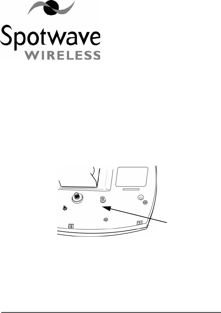
5.1 DU & HPCU LED Indicators
5.1.1 DU
Figure 5.1 DU and HPCU LED locations
The following DU LED indications are only valid during the
second complete rotation of the DU.
LED
IS
RED
: the DU is not capturing an adequate enough
signal for the system to operate. Will also show RED when
signal is too strong (not expected to be a common situation).
DU LED

DISPLAY INFORMATION
38 SpotCell 612 Adaptive Repeater
LED
IS
YELLOW
: the captured signal is within range and the
system will function, but the DU is NOT aligned to capture
the strongest signal available at its current location. NOTE:
the service provider (Carrier) may specify that the DU be
aligned to a basestation site (azimuth) that does not produce
the strongest signal.
LED
IS
GREEN
: during the second rotation of the DU this
indicates that the DU is nearly optimally aligned for the
current location. A minor alignment adjustment may be
needed, using the ARU LCD signal strength and coverage
display as indicators of optimum alignment.
5.1.2 HPCU
The HPCU LED also indicates three conditions. They are:
LED
IS
OFF
: no DC power supply present
LED
IS
RED
: power present + system alarm condition
LED
IS
GREEN
: power present + no alarm condition
Spotwave Wireless Inc. 39
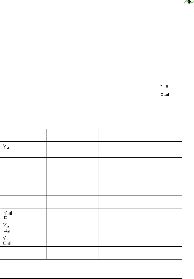
5.2 ARU LCD Action Messages
The ARU LCD display shows two types of messages. Action
messages and standard messages.
Action messages provide guidance to the installer. Their display
on the LCD is controlled by the adaptive algorithm. Examples
were given previously in this Chapter.
The ARU LCD displays system status and signal strength. The
signal strength is indicated by the signal strength bars ( ) and
the coverage strength is indicated by the coverage bars ( ).
Table 1 shows the various action messages, and if necessary what
action should be taken.
TABLE 1. LCD Action Messages
MESSAGE 1 MESSAGE 2
(alternates with Message 1)
ACTION REQUIRED or COMMENTS
CHxxx
INSTALL MODE
Weak Signal
Try turning DU
DU is not optimally positioned.
Realign the DU to another azimuth.
Poor Signal
INSTALL MODE
Poor Signal
Try Turning DU
System will not function.
Realign the DU to another azimuth.
Signal Overdrive
INSTALL MODE
Signal Overdrive
Try Turning DU
RSS too strong.
Realign the DU to another azimuth.
OUT OF SERVICE
System Fault
CHECK CABLE
CONNECTIONS
OUT OF SERVICE
System Fault
CALL PRODUCT SUPPORT Telephone Service Line:
1-877-610-9586
CHxxx
MOVE HPCU
none Increase isolation by moving HPCU.
CHxxx
In Service
none Signal weak and coverage poor. Improve RSS
& improve isolation.
CHxxx
In Service
none Signal weak but coverage good.
No action required.
OUT OF SERVICE
Poor Isolation
OUT OF SERVICE
Try moving HPCU
Increase isolation by moving the HPCU (DU
only if necessary).

DISPLAY INFORMATION
40 SpotCell 612 Adaptive Repeater
CHxxx
In Service
none All OK
No action required
OUT OF SERVICE
Loss of Signal
OUT OF SERVICE
Searching.. .
Temporary loss of service.
No action required.
OUT OF SERVICE
Loss of Signal
OUT OF SERVICE
Try turning DU
24 hr loss of service. Realign or
relocate the DU.
TABLE 1. LCD Action Messages

Spotwave Wireless Inc. 41
5.3 ARU LCD Standard Messages
Standard messages are available at all times. They are shown in
Table 2.
Standard LCD displays are those that are available at all times. An
example is given below. The actual displays may change with the
Software version.
There are 15 standard displays. Only one display is available at a
time. The displays appear in the order shown. They are accessed
by pressing the ARU SCROLL push button. The order of the
displays is as shown in Table 2.
TABLE 2. ARU LCD Standard Messages
MESSAGE (with example) DESCRIPTION
ACT SIG:
ALT SIG:
-85dBm
-79dBm
In-band (ACTive) signal level (at DU, measured at HPCU)
In-band (ALTernate) signal level (at DU, measured at HPCU)
ISOLATION
BACK-OFF:
(15)
0dB
(nn) Downlink Signal Quality Index
a,b,c,d
(SQI)
Downlink gain reduction due to limited DU to HPCU isolation
DL GAIN:
UL GAIN:
109dB
99dB
System gain on downlink
System gain on uplink (approx. 10-dB less than downlink gain)
DVOUT:
UVOUT:
nnnmV
nnnmV
Spotwave Use
DVSET:
UVSET:
nnnmV
nnnmV
Spotwave Use
DVCTL:
UVCTL:
nnnmV
nnnmV
Spotwave Use
START:
STOP:
1950.00MHz
1965.00MHz
Indicates start frequency of downlink in-band signal
Indicates stop frequency of downlink in-band signal
PCB TEMPERATURE
55
o
C
Spotwave Use
WORKING TIME 0d 00h15:44 Indicates days/hours/minutes since last power up
ELAPSED TIME 10days 13hr Indicates total time in days/hours for system operation
HPCU V
DU V
8.08 V
10.5 V
Indicates DC supply voltage at input to the HPCU and DU coaxial
cables respectively.

DISPLAY INFORMATION
42 SpotCell 612 Adaptive Repeater
Standard Display 1 - Active & Alternate RSS
Display 1 indicates the carrier level into the DU as measured at
the ARU. The ACTive carrier is the wanted in-band signal and the
ALTernate is the unwanted out-of-band signal level (before filter-
ing).
Standard Display 2 - Signal Quality Index & Back-Off
Display 2 confirms the quality of the installation with respect to
it’s potential to deliver rated coverage. Coverage may require the
installer to optimize the DU and HPCU locations. An optimal DU
location will deliver a strong, high quality downlink signal that
exhibits minimum fading. Success in this is indicated on the ARU
display via the Signal Quality Index or SQI on Display 2 (as
shown in Table 2 ). On the LCD, SQI is labelled as “ISOLATION
(
nn
)”. High quality downlink signals have an SQI less than 60.
An optimal HPCU location will provide coverage where it is
required while satisfying the HPCU to DU isolation need.
Where available isolation is less than the gain required to achieve
rated output power, the system gain is reduced by the adaptive
algorithm to ensure stability. The resulting gain reduction is
DU CUR: 812mA Current being drawn by the DU
S/W WDT
H/W WDT
0
0
Software watchdog timer
Hardware watchdog timer
Tests the LCD display by lighting all segments
S/W v2.3.9.0
@ 05-01
Displays software version and date code
a. For SQI >80, do not install the DU at this position.
b. For SQI >59, try another DU location
c. For SQI <60, < 3-dB back-off. Good downlink signal quality.
d. For SQI <20, 0-dB back-off. Excellent downlink signal quality.
TABLE 2. ARU LCD Standard Messages

Spotwave Wireless Inc. 43
labelled as back-off on the LCD Display 2. Back-off is displayed in
dB units.
When isolation is high, ACT RSS is high, ALT RSS is not excessive
and fading is minimum, and isolation is adequate - the adaptive
algorithm will deliver rated output power. However, maximum
coverage will be delivered, if and only if, the installer has located
and oriented the HPCU such that it provides the coverage where
it is needed. That is, located where the HPCU antenna pattern
matches the required coverage area with no significant RF dense
materials in the way.
Standard Display 3 - Downlink & Uplink Gain
Display 3 in Table 2 indicates the actual gain provided for both
the downlink and uplink directions. The indicated gain will be
high only if high gain is needed (due to a low downlink RSS) and
the SQI is good.
Standard Displays 4 to 15
Displays 4 to 13 shown in Table 2 are not important to the
installer and not discussed here. Display 15 identifies the Spot-
Cell
Software version.

DISPLAY INFORMATION
44 SpotCell 612 Adaptive Repeater
Spotwave Wireless Inc. 45
Appendix A – SpotCell 612 Specifications
Note:
Spotwave Wireless has the right to change specifications
without notice.
A.1 Compliance
The SpotCell 612 repeater uses RF energy and complies with 47
CFR, Part 1.1310, Radiofrequency Exposure Limits for fixed
installations, pursuant to 47 CFR, Part 24.52 of the FCC rules and
regulation for PCS equipment and 47 CFR, Part 1.1310(b).

46 SpotCell 612 Adaptive Repeater
A.2 Antennas:
A.3 Architecture
TABLE A1. Antenna Specifications
DU Antenna HPCU Antenna
Gain (dBi) 11.5 11.5
Elevation Beamwidth - typical (dg) 36 36
Azimuth Beamwidth - typical (dg) 46 46
Front-to-Back Ratio (dB) 26 26
Polarization Vertical Vertical
TABLE A2. System Specifications
Frequency Band of Operation Uplink: 1850-1890 MHz
Downlink: 1930-1970 MHz
Formats Supported PCS CDMA
Coverage Fully adaptive, supports multiple simultaneous users
Outdoor Range: to 825-ft
Indoor Range: Up to 50,000-ft
2
in large open areas
System Gain Automatic, fully adaptive,
Maximum 115-dB downlink (for Downlink input of -91 dBm EIRP),
Maximum 105-dB uplink
Minimum 68-dB downlink (for Downlink input of -44 dBm EIRP),
Minimum 58-dB uplink
Rated Downlink output per carrier is always +24 dBm
Downlink Operating Range -96 to -44 dBm (receive isotropic power) - coverage reduced at lev-
els below -91 dBm
Input Overload Protection Uplink: Fully adaptive
Downlink: Fully adaptive
Maximum Output Levels (radiated) Uplink: 30-dBm EIRP maximum (composite)
Downlink: 30-dBm max (composite), managed per channel at 24-
dBm per channel)
Rated Downlink output per carrier is +24 dBm (for a maximum of
four carriers. If number of carriers exceeds four, per carrier power is
reduced such that composite downlink output is always +30 dBm
EIRP)
Typical 20dB BW Customer specific: 5.37-MHz, 10.74-MHz, 16.1-MHz (nominally
5-MHz, 10-MHz and 15-MHz respectively)
Third Order Intercept (radiated) Uplink: 45-dBm EIRP
Downlink: 45-dBm EIRP
Power Supply AC Input Voltage Range: 90-V to 130-V rms, 50 to 60-Hz

Spotwave Wireless Inc. 47
Power Consumption 50-W (heater OFF)
125-W (heater ON)
Standby Battery Time 2-hr. (heater disabled)
TABLE A2. System Specifications

48 SpotCell 612 Adaptive Repeater
A.4 Physical
A.5 Installation
Diagnostics
TABLE A3. l Physical Specifications
Operating Temperature DU & HPCU: -40
°
to +55
°
C
ARU: -40
°
to +55
°
C (with heater)
Size DU & HPCU: 14"w 10.5" h 3.5" d
ARU: 10" w 18"h 7" d
Weight DU & HPCU: 4-lb.
ARU c/w battery: 25-lb.
RF Connectors & Impedance Type F 75-ohm
RF Cable 2-RG-11 Quad shielded required, 1-41’supplied
1- ordered for required length
(System supports up to 164 ft. or 50 m)
TABLE A4. Installation Requirements
Installation Time Less than one hour typical
Outdoor Unit Alignment No prior knowledge of base station location required
Built in alignment algorithm (LED Indicator on outdoor unit)
Test Equipment None required
No RF knowledge required for installation
User Controls None, setup and operation is fully automatic
TABLE A5. Diagnostic Tools
Fault Indicators LED on DU (installation only)
LED on HPCU (during normal operation)
ARU (wireless modem, LCD display, AC power light)
Remote Connectivity Ethernet port on ARU and wireless modem
System Interrogation Multifunction LCD indicator ARU

Spotwave Wireless Inc. 49
www.spotwave.com
Spotwave Wireless Inc.
1 Hines Road
Ottawa ON K2K 3C7
Canada
2004 Spotwave Wireless Inc. All rights reserved.
Spotwave and SpotCell are trademarks of Spotwave Wireless Inc. Patents pending.

50 SpotCell 612 Adaptive Repeater