Spotwave Wireless SPOTCELL0013 DU 1900 Full Band User Manual SpotCell 11x QuickStart 14Sep04
Spotwave Wireless Ltd. DU 1900 Full Band SpotCell 11x QuickStart 14Sep04
Contents
- 1. User guide
- 2. Quick start guide
Quick start guide
™
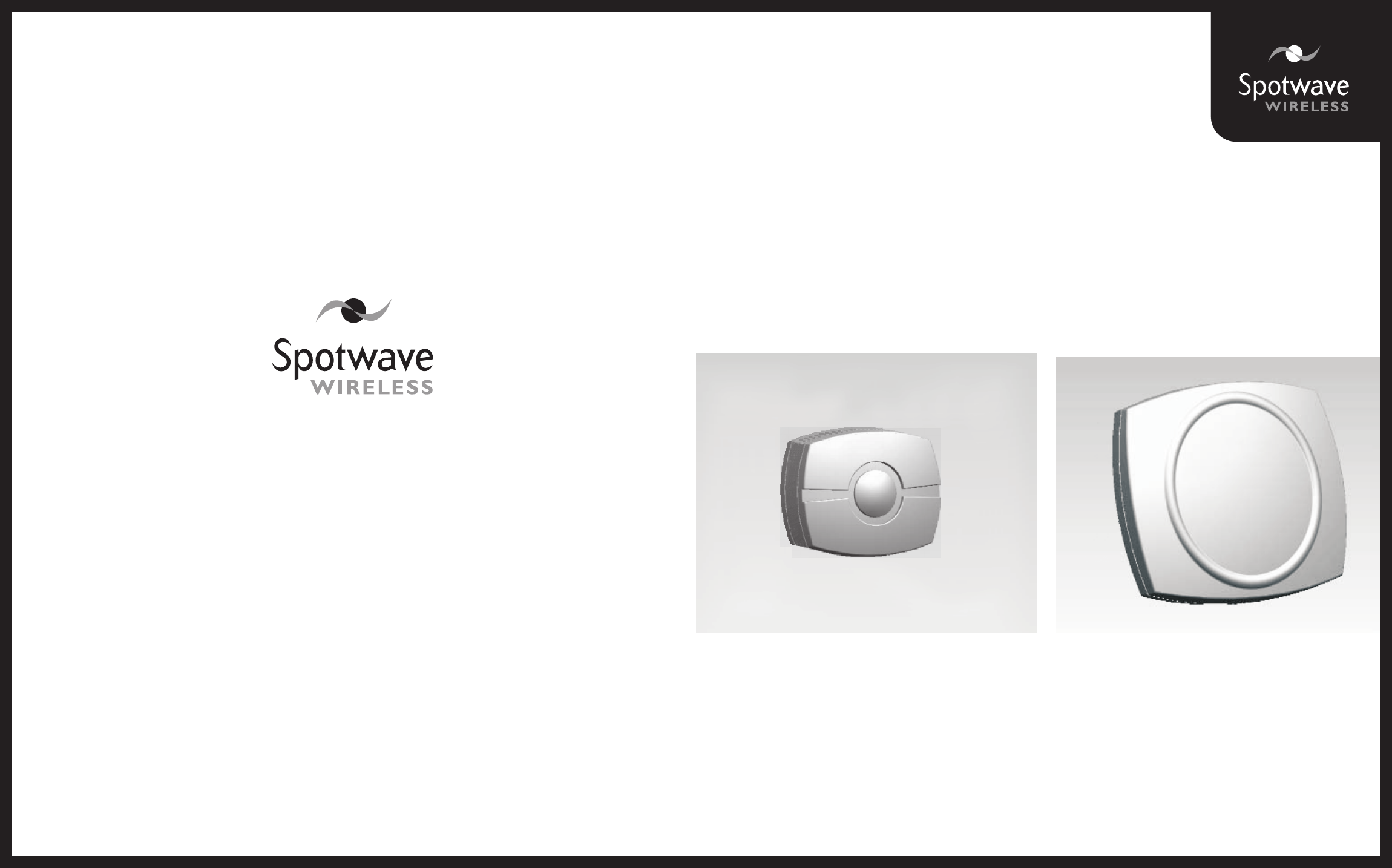
SpotCell 111s/112s
™
SpotCell 111s/112s
Quick Installation GuideQuick Installation Guide
www.spotwave.com
Spotwave Wireless Inc. 1 Hines Road, Ottawa ON K2K 3C7 Canada
780-0000x-01-01
© 2004 Spotwave Wireless Inc. All rights reserved. Printed in Canada
Spotwave and SpotCell are trademarks of Spotwave Wireless Inc. Patents pending.
If required, more detailed information on installing a
SpotCell system can be found in the User Manual
which is also available for downloading at
www.spotwave.com/2003/support/manuals.htm.
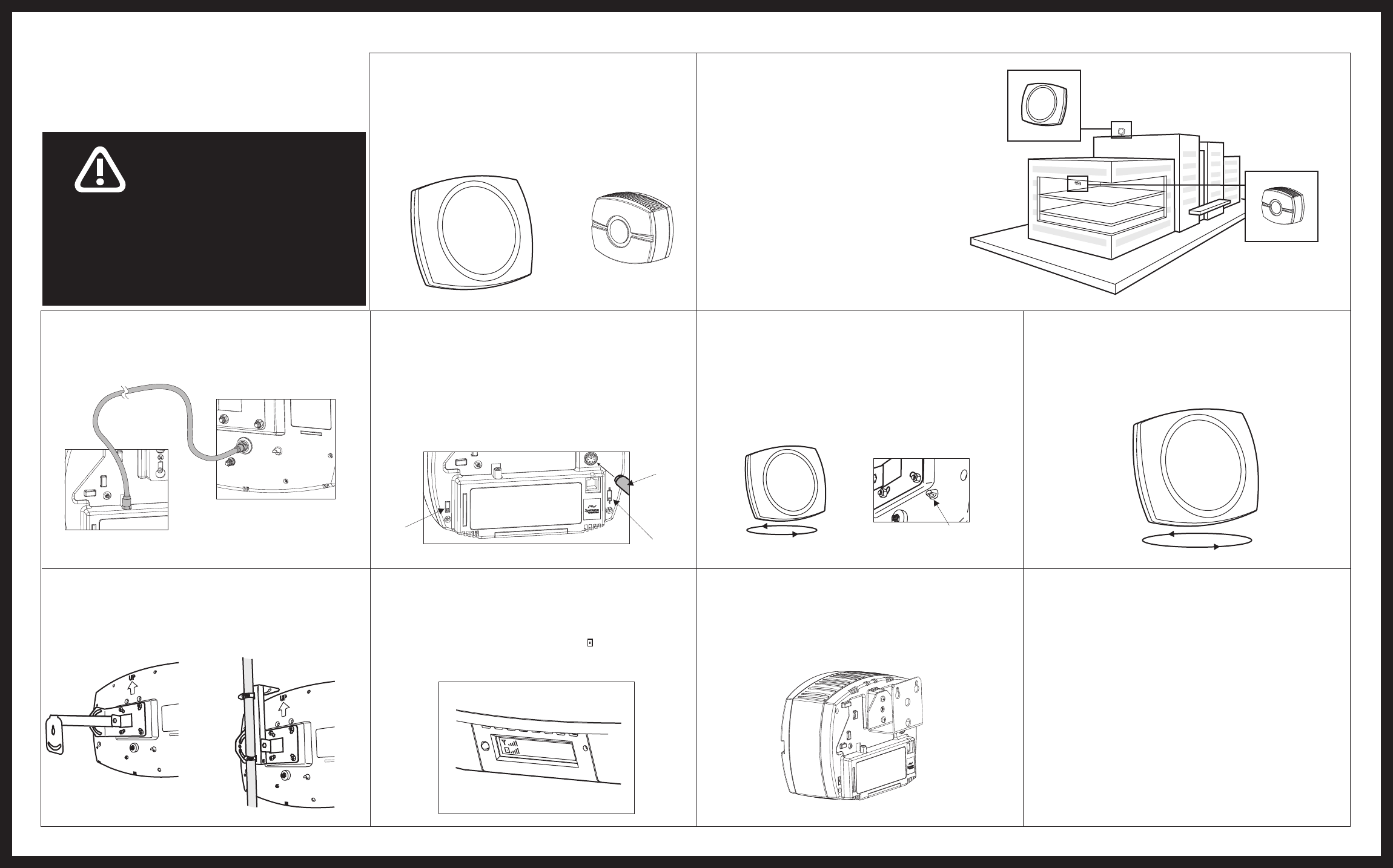
2. Location
The DU can be mounted anywhere your cell
phone works. This may be on a rooftop (typical
rural set-up), on the side of a building, or inside
a building (typical downtown set-up). The CU
will be mounted inside the building where your
cell phone does not work.(The illustration at
the right depicts a typical installation.)
To start the installation, place the DU and CU
in the general areas where they are to be located.
Do not physically mount them at this time.
Maximum separation between the DU and CU,
and back-to-back positioning are optimal when
both are mounted indoors.
For quick installation of SpotCell:For quick installation of SpotCell:
For your safety beware of power lines and ensure that
appropriate safety measures are maintained at all times
during the installation of the SpotCell 100 equipment.
Contact with high-voltage power lines could result in
death or serious injury.
,
WARNING
6. Align DU - 2nd rotation
Again rotate the DU. When the LED turns green, stop the
rotation. This is the direction the DU must face when
mounted.
10. Final Checklist
1.Properly ground the DU via the grounding bolt.
2.Ensure that there is a drip loop on the cable connecting
to the DU.
3.Firmly affix the cable to the building where it runs
between the DU and CU.
7. Mount DU
Now mount the DU. Typical installations are pictured below .
Wall Mount Pipe Mount with Hose Clamp
LED
4. Set Mode and AP Switch
Set the switch on the bottom of the CU to “1” (install).
If only one of the split bands is currently active, then set the
AP switch to the active band. If both bands are active, then
the AP switch can be in either position for DU alignment.
Connect the power supply to the CU, and then plug the
adapter into the AC outlet.
8. Set CU to Active
Move the switch on the bottom of the CU to “2” (active).
Hold the CU in the location to be mounted. The LCD on
the bottom of the CU indicates coverage ( ) by the number
of bars; more bars indicate better coverage.
DU
(outward-facing unit) CU
(indoor unit)
1. Parts List
• Mounting kit• Donor Unit (DU)
• Coverage Unit (CU)
• Cable (80'/25 m)
• Power supply
xxxCH
ISvcen er i
ISvcen er i
5. Align DU - 1st rotation
In the location where the DU is to be mounted, rotate the
unit in a complete circle. The LED on the back will turn red
or green during the rotation.
9. Mount CU
Mount the CU from a wall or ceiling, close to the center
of the area requiring coverage.
Rotate 360°
3. Connect CU to DU
Connect the CU and DU with the cable provided.
Back of DU
Back of CU
Back of CU
Mode
Switch
Power
Connector
AP
Switch