Stratasys ALARIS 3D RAPID PRINTER User Manual Alaris30 User Guide

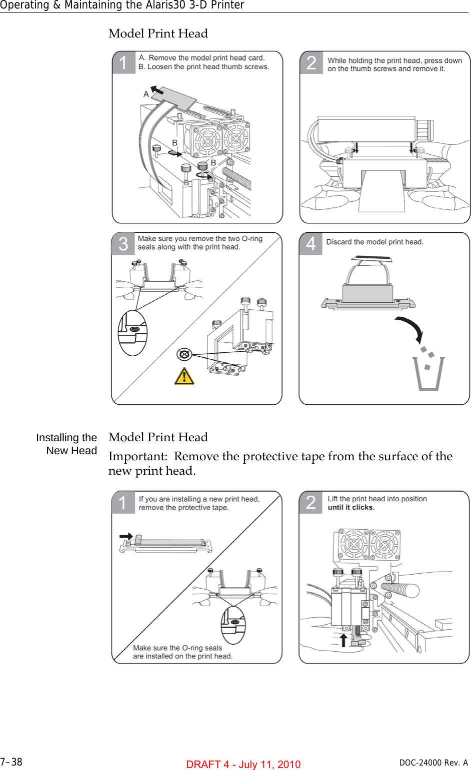
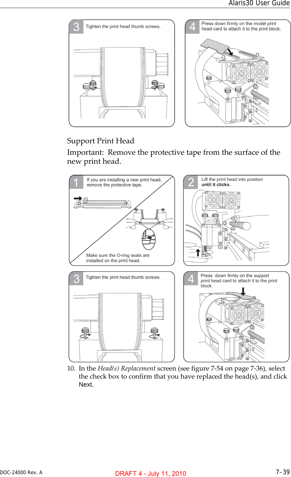
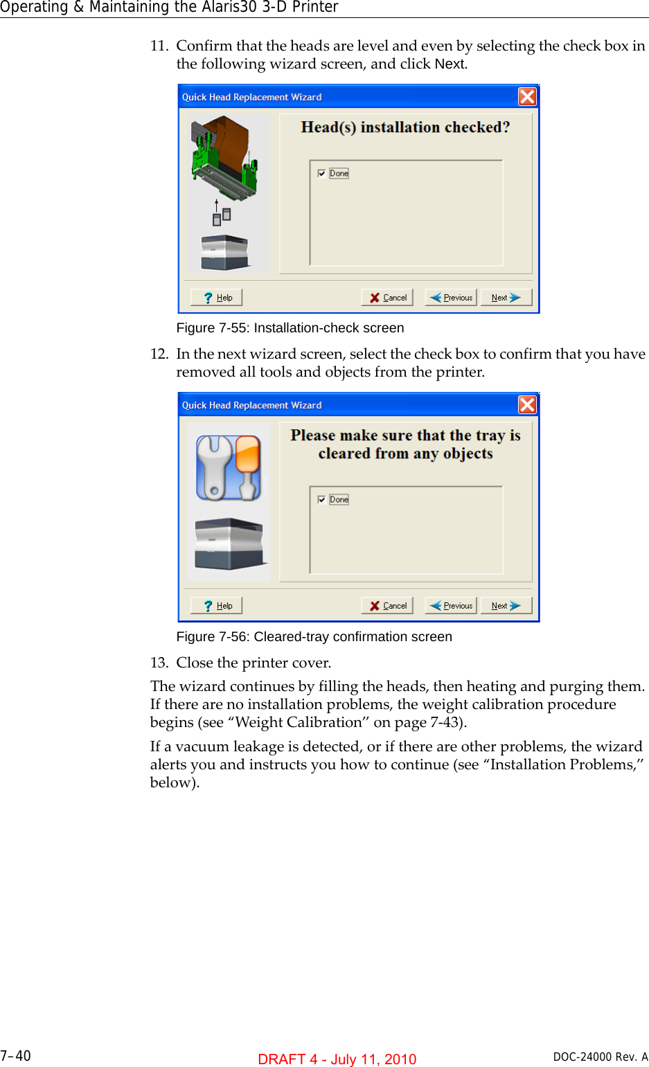
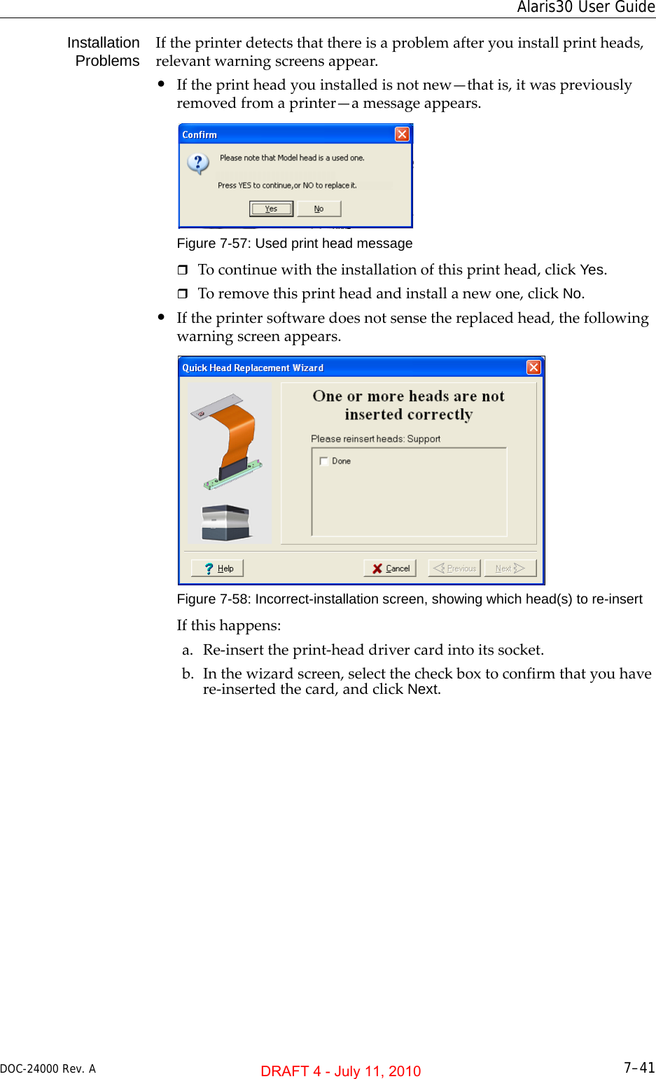
Stratasys Ltd 3D RAPID PRINTER Alaris30 User Guide

Users Manual

User GuideEnglishAlaris303-D Printer SystemDRAFT 4 - July 11, 2010
DRAFT 4 - July 11, 2010
DOC-24000 Rev. A iiiCopyrightCopyright©2010ObjetGeometriesLtd.Allrightsreserved.ThisdocumentationcontainsproprietaryinformationofObjetGeometriesLtd.ThisinformationissuppliedsolelytoassistauthorizedusersofAlaris303‐Dprintingsystems.Nopartofthisdocumentmaybeusedforotherpurposes,anditmaynotbedisclosedtootherparties.Thespecificationsonwhichthisdocumentisbasedaresubjecttochangewithoutnotice.Nopartofthisbookmaybereproducedinanyformorbyanymeans,norstoredinadatabaseorretrievalsystem,withoutpriorpermissioninwritingfromObjetGeometriesLtd.IfthisdocumentisdistributedasaPDFfile,youmayprintitforinternaluse.TrademarksThefollowingareregisteredtrademarksofObjetGeometriesLtd.:Objet®,FullCure®.ThefollowingaretrademarksofObjetGeometriesLtd.:Eden,Eden500V,Eden350V,Eden350,Eden330,Eden260,Eden260V,Eden250,Connex,Connex500,Connex350,Alaris,Alaris30,Alaris24,PolyJet,PolyJetMatrix,PolyLog,ObjetStudio,JobManager,SHR,TangoBlack,TangoGray,TangoPlus,VeroBlue,VeroGray,VeroWhite,VeroBlack,DurusWhite,RoseClear,Clear,DigitalMaterials.MicrosoftandMicrosoftXParetrademarksofMicrosoftCorporation.Allnamesofproductsandservicescitedinthisbookaretrademarksorregisteredtrademarksoftheirrespectivecompanies.FCC ComplianceThe3‐DprintingsystemsreferredtointhisguidehavebeentestedandfoundtocomplywiththelimitsforaClassAdevicepursuanttopart15oftheFCCrules.Theselimitsprovidereasonableprotectionagainstharmfulinterferencewhentheequipmentisoperatedinacommercialenvironment.Objet3‐Dprintingsystemsgenerate,useandcanradiateradiofrequencyenergy.Ifnotinstalledandusedinaccordancewithinstructionsintherelevaninstallationanduserguides,thesesystemsmaycauseharmfulinterferencetoradiocommunications.OperationofObjet3‐DprintingsystemsinresidentialareasmaycauseunacceptableinterferencetoradioandTVreception,requiringtheoperatortotakewhateverstepsarenecessarytocorrecttheinterference.NOTE:ObjetGeometriesisnotresponsibleforradioorTVinterferencecausedbyunauthorizedmodificationtothisequipment.Suchmodificationscouldvoidtheuser’sauthoritytooperatetheequipment.Equipment RecyclingIntheEuropeanUnion,thissymbolindicatesthatwhenthelastuserwishestodiscardaproduct,itmustbesenttoappropriatefacilitiesforrecoveryandrecycling.Forinformationaboutproperdisposal,checkyourpurchasecontract,orcontactthesupplieroftheequipment.Limitation of LiabilityTheproduct,softwareorservicesarebeingprovidedonan“asis”and“asavailable”basis.Exceptasmaybestatedspecificallyinyourcontract,ObjetGeometriesLtd.expresslydisclaimsallwarrantiesofanykind,whetherexpressorimplied,including,butnotlimitedto,anyimpliedwarrantiesofmerchantability,fitnessforaparticularpurposeandnon‐infringement.YouunderstandandagreethatObjetGeometriesLtd.shallnotbeliableforanydirect,indirect,incidental,special,consequentialorexemplarydamages,includingbutnotlimitedto,damagesforlossofprofits,goodwill,use,dataorotherintangiblelosses(evenifObjethasbeenadvisedofthepossibilityofsuchdamages),resultingfrom:(i)theuseortheinabilitytousetheproductorsoftware;(ii)thecostofprocurementofsubstitutegoodsandservicesresultingfromanyproducts,goods,data,software,informationorservicespurchased;(iii)unauthorizedaccesstooralterationofyourproducts,softwareordata;(iv)statementsorconductofanythirdparty;(v)anyothermatterrelatingtotheproduct,software,orservices.Thetextanddrawingshereinareforillustrationandreferenceonly.Thespecificationsonwhichtheyarebasedaresubjecttochange.ObjetGeometriesLtd.may,atanytimeandwithoutnotice,makechangestothisdocument.ObjetGeometriesLtd.,foritselfandonbehalfofitssubsidiaries,assumesnoliabilityfortechnicaloreditorialerrorsoromissionsmadeherein,andshallnotbeliableforincidental,consequential,indirect,orspecialdamages,including,withoutlimitation,lossofuse,lossoralterationofdata,delays,orlostprofitsorsavingsarisingfromtheuseofthisdocument.DRAFT 4 - July 11, 2010
iv   DOC-24000 Rev. APatentsThisproductiscoveredbyoneormoreofthefollowingU.S.patents:5,263,1305,287,4355,386,5005,519,8165,695,7086,259,9626,569,3736,644,7636,658,3146,850,3346,863,8597,183,3357,209,7977,225,0457,300,6197,364,6867,368,4847,369,9157,479,5107,500,8467,604,7687,628,857ObjetGeometriesLtd.http://www.objet.comDOC‐24000RevisionAJuly2010DRAFT 4 - July 11, 2010
DOC-24000 Rev. A v1AboutThisGuideUsingThisGuide ............................................................................................................................... 1–2ForMoreInformation........................................................................................................................ 1–2TermsUsedinThisGuide................................................................................................................ 1–32 SafetySafetyFeatures ................................................................................................................................... 2–2SymbolsandWarningLabels .......................................................................................................... 2–3SafetyGuidelines ............................................................................................................................... 2–4PrinterInstallation .............................................................................................................................. 2–4PrinterOperation ................................................................................................................................ 2–4UVRadiation ....................................................................................................................................... 2–4PrinterMaintenance ........................................................................................................................... 2–4ModelandSupportMaterials ........................................................................................................... 2–5FirstAidforWorkingwithPrintingMaterials.............................................................................. 2–6ContactwithSkin................................................................................................................................ 2–6ContactwithEyes ............................................................................................................................... 2–6Ingestion............................................................................................................................................... 2–6Inhalation ............................................................................................................................................. 2–6WasteDisposal ................................................................................................................................... 2–73 IntroducingtheAlaris3‐DPrintingSystemWorkConfigurations......................................................................................................................... 3–2SourceFiles ......................................................................................................................................... 3–3STLFiles ............................................................................................................................................... 3–3SLCFiles............................................................................................................................................... 3–3PrintingMaterials .............................................................................................................................. 3–4AvailableMaterials............................................................................................................................. 3–4Storage .................................................................................................................................................. 3–4ShelfLife............................................................................................................................................... 3–5ExposuretoLight................................................................................................................................ 3–5SafetyConsiderations......................................................................................................................... 3–5Disposal................................................................................................................................................ 3–5WorkEnvironment............................................................................................................................ 3–6WorkstationRequirements............................................................................................................... 3–6PreparingFilesforUsewithAlaris3‐DPrintingSystems .......................................................... 3–7ConvertingCADFilestoSTLFormat.............................................................................................. 3–7ConvertingFilestoSLCFormat ....................................................................................................... 3–7ObjetSoftware.................................................................................................................................... 3–84 InstallingObjetSoftwareHowtoInstallSoftwarefortheAlaris3‐DPrintingSystem ....................................................... 4–2ContentsDRAFT 4 - July 11, 2010
Alaris30  vi DOC-24000 Rev. A5UsingObjetStudioOpeningObjetStudio........................................................................................................................ 5–2Toolbars.................................................................................................................................................5–2PreparingModelsforProduction.................................................................................................... 5–3OpeningSTL&SLCFiles...................................................................................................................5–3CopyingandPastingObjects.............................................................................................................5–5SelectingObjects ..................................................................................................................................5–5ArrangingtheObjetStudioScreen.................................................................................................. 5–6PositioningObjectsontheBuildTray ............................................................................................ 5–8AutomaticPositioning ........................................................................................................................5–8ManualPositioning ............................................................................................................................. 5–9ModelOrientation............................................................................................................................ 5–10ManipulatingObjectsontheBuildTray ...................................................................................... 5–11ObjectPositionontheZ‐Axis ..........................................................................................................5–11RepositioningObjects .......................................................................................................................5–12ValidObjectPlacement....................................................................................................................5–14UsingaGridtoPositionObjects .....................................................................................................5–14ChanginganObject’sOrientation...................................................................................................5–15FreezinganObject’sOrientation.....................................................................................................5–16SurfaceFinish.....................................................................................................................................5–16DefaultObjectProperties .................................................................................................................5–17DisplayOptions................................................................................................................................ 5–18DisplayColors....................................................................................................................................5–19DisplayingLargeFiles ......................................................................................................................5–20TrayViewingOptions ......................................................................................................................5–21HandlingCompletedTrays............................................................................................................ 5–23TrayValidation ..................................................................................................................................5–23ProductionEstimates ........................................................................................................................5–24SavingtheTrayFile...........................................................................................................................5–24PrintingtheTrayFile ........................................................................................................................5–24AdditionalObjetStudioFeatures .................................................................................................. 5–26DividingObjects ................................................................................................................................5–26ChoosingtheSupportStrength .......................................................................................................5–26“Smartcast”—FillingModelswithSupportMaterial...................................................................5–27DisplayingtheCrossSectionofObjects.........................................................................................5–28PrintingtheScreenDisplayonPaper.............................................................................................5–29SavingtheScreenDisplayasanImage File ..................................................................................5–29ExportingandImportingObjetBuildTrays .................................................................................5–29Advanced‐ModeFeatures .............................................................................................................. 5–30SaveTrayAs…...................................................................................................................................5–31ConfiguringtheGLDriver...............................................................................................................5–326UsingJobManagerClientJobManager ............................................................................................................................ 6–2JobManagerScreen.............................................................................................................................6–3JobManagerOperations.....................................................................................................................6–4ConfiguringUserAlerts .....................................................................................................................6–5ServerJobManager............................................................................................................................ 6–7JobManagerScreen.............................................................................................................................6–8JobManagerOperations.....................................................................................................................6–9MakingchangestoaJob...................................................................................................................6–10UserAlerts..........................................................................................................................................6–11SendingtheTraytothe3‐DprinterforProduction .....................................................................6–12DRAFT 4 - July 11, 2010
User GuideDOC-24000 Rev. A vii7 Operating&MaintainingtheAlaris303‐DPrinterStartingtheAlaris30Printer............................................................................................................. 7–2LoadingModelandSupportCartridges ........................................................................................ 7–3ProducingModels.............................................................................................................................. 7–5PrinterInterfaceColor Key................................................................................................................ 7–7PrintingIndicators .............................................................................................................................. 7–8ResumingProductionAfterPrintinghasStopped ....................................................................... 7–9ChangingtheModelMaterial........................................................................................................ 7–10KeepingtheAlarisPrinterinIdleMode ...................................................................................... 7–14ShuttingDowntheAlarisPrinter.................................................................................................. 7–15ShutdownWizard............................................................................................................................. 7–15MaterialFlush/FillWizard .............................................................................................................. 7–17MaintainingtheAlarisPrinter....................................................................................................... 7–20RoutineMaintenanceSchedule....................................................................................................... 7–20CleaningthePrintHeads................................................................................................................. 7–21PatternTest ........................................................................................................................................ 7–23ImprovingPrintQuality .................................................................................................................. 7–24CleaningandReplacingtheWiper ................................................................................................ 7–24CleaningandReplacingtheRollerWasteCollector.................................................................... 7–27AligningthePrintHeads................................................................................................................. 7–30ReplacingPrint Heads...................................................................................................................... 7–34CalibratingtheLoadCells ............................................................................................................... 7–45ReplacingtheOdorFilter ................................................................................................................ 7–47ReplacingtheUVLamp................................................................................................................... 7–48ReplacingtheWasteContainer....................................................................................................... 7–53CleaningtheExteriorPanels ........................................................................................................... 7–55Backing‐UpandRestoringPrinterSettings .................................................................................. 7–56ReInitiateWizard .............................................................................................................................. 7–568 HandlingPrintedModelsRemovingModelsAfterPrinting .................................................................................................... 8–2RemovingtheSupportMaterial ...................................................................................................... 8–2StoringModels ................................................................................................................................... 8–3DRAFT 4 - July 11, 2010
Alaris30  viii DOC-24000 Rev. ADRAFT 4 - July 11, 2010
DOC-24000 Rev. A 1–1About This GuideUsingThisGuide................................................................................. 2ForMoreInformation ......................................................................... 2TermsUsedinThisGuide.................................................................. 3DRAFT 4 - July 11, 2010
About This Guide1–2 DOC-24000 Rev. AUsing This GuideThisuserguideprovidesinstructionsforinstalling,operatingandmaintainingAlaris3‐Dprintingsystems.Itexplainshowtousefeatures,andprovidespracticalexamplestoguideyouasyouusethesystem.ThisdocumentismeanttobeusedwiththeAlaris303‐Dprinter,runningsoftwareversion30.2.1,andwithObjetStudiosoftwareversion8.5.9.Thisguideassumesthat:•allthehardware,software,andnetworkcomponentsofyourAlarissystemareinstalled,configured,andoperatingcorrectly.•theoperatorhasaworkingknowledgeoftheWindows®PCplatform.For More InformationVisithttp://www.objet.com/formoredetailsaboutObjet’stechnology,productsandconsumables,andforserviceandsupportcontacts.ForotherdocumentsthatrelatetoAlaris303‐Dprintingsystems,andforthisdocumentinotherlanguages,contactyourregionalObjetCustomerSupportoffice.Ifyouhaveanyquestionsabouttheinformationpresentedinthisdocument,orifyouhaveanycommentsorsuggestionsforfutureeditions,pleasesendamessagetosupport@objet.com.DRAFT 4 - July 11, 2010
DOC-24000 Rev. A 1–3Alaris30 User GuideTerms Used in This Guidebuildtray InObjetStudio:ThesurfacedisplayedonthescreenthatrepresentstheactualbuildtrayintheAlarisprinter.IntheAlarisprinter:Thesurfaceuponwhichmodelsareproduced.cleaningfluid Cleanserforflushingmodelfeedtubesandtheprintingblock,usedtocompletelyremovemodelmaterialfromthesystembeforeloadinganothertypeofmaterialintheprinter.Thecleaningfluidissuppliedinmodel‐materialcartridges.client/userworkstation TheworkstationonwhichObjetsoftwareisinstalled,usedforpreparingbuildtraysforproductiononAlarisprinters.(Thereisnolimittothenumberofclientworkstationsinthelocalnetwork.)Alaris™printer TheObjet3‐Dprinterreferredtointhisguide.Alariscomputer ThecomputerinsidetheAlarisprinterthatoperatesit.(Thisissometimesreferredtoasthe“embedded”computer.)Alarisprinterinterface TheGUI(graphicaluserinterface)usedforcontrollingtheAlarisprinter.Alarissoftware SoftwarerunningonthecomputerinsidetheAlarisprinterthatcontrolsallprinteroperations.host/serverworkstation TheworkstationonwhichthefullversionofJobManagerisinstalled.ThisworkstationinterfacesdirectlywiththeAlarisprinterandistypicallypositionednexttoit.JobManager™ ThesoftwarethatmanagesproductionjobsbeforetheyaresenttotheAlarisprinter.modelmaterial Materialusedforbuildingmodels.ObjetStudio™ Thesoftwarewithwhichuserspreparejobsforproducingmodels.OBJTF(ObjetTrayFormat) Theextensionofafilethatcontainsalloftheinformationneededforamodel‐printingjobonObjet3‐Dprinters.AnobjtffileisusedtosendaprintjobtoanObjet3‐Dprinter.OBJZF(ObjetZFormat) Theextensionofacompressed“wrapper”filecontainingallofthefilesusedinanObjetStudiobuildtray.Usingobjzffiles,aprintingjobcanbesavedasasinglefile,forconvenientstorageandtransfer.resin ThebasesubstancefromwhichphotopolymerprintingmaterialsaremadeforuseinAlarisprinters.InObjetStudio,JobManagerandAlarissoftware,“resin”referstocartridgesofmodelandsupportmaterials.SLC AfiletypeusedwithObjetsoftware.(Thesefilesarebitmapsofindividualslicesoftheobject.Formoreinformation,seepage 3‐3.)DRAFT 4 - July 11, 2010
About This Guide1–4 DOC-24000 Rev. ASTL AfiletypeusedwithObjetsoftware.(Formoreinformation,seepage 3‐3.)supportmaterial Materialusedforsupportingthestructureofmodelsduringproduction.DRAFT 4 - July 11, 2010
DOC-24000 Rev. A 2–1SafetySafetyFeatures..................................................................................... 2SymbolsandWarningLabels ............................................................ 3SafetyGuidelines................................................................................. 4PrinterInstallation ................................................................................ 4PrinterOperation .................................................................................. 4UVRadiation ......................................................................................... 4PrinterMaintenance ............................................................................. 4ModelandSupportMaterials ............................................................. 5FirstAidforWorkingwithPrintingMaterials ............................... 6WasteDisposal..................................................................................... 7DRAFT 4 - July 11, 2010
Safety2–2 DOC-24000 Rev. ASafety FeaturesAlaris3‐DprintersaredesignedtocomplywithCEandFCCstandards.Theyareequippedwiththefollowingsafetyfeatures:Figure 2-1: Front and back views of the Alaris30 printerCoverinterlockswitch ThepowersuppliedtotheUVlampandthemotionmotorsisturnedoffwhenthecoverisopened.WARNING:Donotdefeat(override)theinterlockswitch.Doingsocouldresultinseriouspersonalinjury.Iftheinterlockswitchdoesnotfunctioncorrectly,donotusetheprinter,andcontactyourserviceprovider.Coverlock Thecoverislockedwhiletheprinterisworking.Itisreleasedwhentheprinterrevertstopauseorstopmode.WARNING:Donotdefeat(override)thesafetylock.Doingsocouldresultinseriouspersonalinjury.Ifthesafetylockdoesnotfunctioncorrectly,donotusetheprinter,andcontactyourserviceprovider.UVscreenThetransparentsectionofthecoverblocksharmfulUVradiation,allowingtheoperatortoviewthemodelasitisbeingmade.Circuitbreaker Thepowertotheprinteristurnedoffincaseofelectricalovercurrent.Note: The circuit breaker is only accessible to service personnel.Groundedchassis Thechassisoftheprinterisgrounded,topreventelectricalshock.Note: The power outlet must be properly grounded, in accordance with the local electric code, to provide this protection.UV screenCover interlock switchCircuit breakerIf the Alaris 3-D printing system is not used as specified in this guide, the safety features may not provide adequate protection.DRAFT 4 - July 11, 2010
DOC-24000 Rev. A 2–3Alaris30 User GuideSymbols and Warning LabelsThisfollowingtableliststhewarninglabelslocatedonorinAlarisprinters.Warning Symbol Meaning Location CommentsHazard(general) Onthenameplateonthebackoftheprinter.Readtheinstructionsinthisdocumentbeforeoperatingtheprinter.HotsurfaceOntheprint‐headblock. Riskofburns.Donottouchthissurfaceafterprinting.HighvoltageNeartheUVlampconnector.Nearthepower‐supplyenclosures.Riskofelectricshock.Ultravioletradiation NeartheUVlamp. Riskofinjuryfromultravioletradiation.Movingparts Ontopoftheprintingassembly. Riskofinjuryfrommovingparts.DRAFT 4 - July 11, 2010
Safety2–4 DOC-24000 Rev. ASafety GuidelinesThefollowinggeneralguidelines,togetherwiththeinstructionsprovidedthroughoutthisuserguide,ensureusersafetywhileoperatingandmaintainingtheAlarissystem.Ifthesystemisnotoperatedasspecified,theuserʹssafetymaybecompromised!Printer Installation ¾InstallationandremovaloftheAlarisprintershouldonlybedonebyqualifiedservicepersonnel.¾Connecttheprintertotheelectricoutletusingapowercordthatissafety‐certified.¾Theelectricoutletshouldbeeasilyaccessible,neartheprinter.¾Neverconnectthepowerplugtoanoutletthatdoesnothaveaground(earth)wire,andneverdisconnecttheground.Doingsomayexposetheoperatortoseriousdangerfromelectricshock.¾Leaveaminimumof20centimetersbetweenventilationopeningsandwallsorotherobjects.Printer Operation ¾TheAlarisprintershouldonlybeoperatedbypersonstrainedbyanObjetcustomer‐supportrepresentative.¾AllpersonneloperatingormaintainingtheAlarisprintershouldknowthelocationoffirstaidandemergencyequipmentandhowtouseit.Neverblockaccesstothisequipment!¾Keepfingersandotherbodypartsclearoftheprintercoverwhenclosingit.¾Neverattempttoopenthemaincoveroftheprinterwhileitisworking!¾Neveroverridetheinterlocksafetyswitch!¾Iftheinterlocksafetyswitcheverfails,donotusetheprinter.¾Severalpartsoftheprinterremainextremelyhotevenafterithasstoppedoperating.AvoidtouchingtheUVlampandtheprintblock.UV Radiation ¾TheUVlampusedintheprinteremitsdangerousradiation.IftheUVlampremainsonwhentheprintercoverisopen,donotstaredirectlyattheUVlight.ShutdowntheprinterandcallyourObjetserviceprovider.Printer Maintenance ¾Serviceoperationsshouldbeperformedonlybyqualifiedpersonnelwhohavebeeninstructedinrelevantsafetyprecautions.¾Notifyco‐workersandthosewhohaveaccesstotheAlarissystembeforebeginningnon‐routineandhazardouswork.Report any potential dangers and safety-related accidents to your safety officer or to other appropriate authorities.DRAFT 4 - July 11, 2010
DOC-24000 Rev. A 2–5Alaris30 User GuideModel and Support MaterialsModelandsupportmaterialsaremadeofchemicalsubstances.Althoughprecautionsmustbetakenwhenhandlingthesematerialsdirectly,allmodelandsupportmaterialsusedbytheAlarissystemarehandledinsealedcartridges.Normally,operatorsoftheAlarisprintershouldneverbedirectlyexposedtohazardousmaterials.Intheunlikelyeventofaleakorspill,followtheinstructionsthatareincludedwiththeprinting‐materialcartridgeused.¾Storecartridgesofmodelandsupportmaterialsindoors,inadryareawithadequateventilation,between16‐27degreesCelsius(60‐81degreesFahrenheit).Neverexposethemtoflames,heat,sparks,ordirectsunlight.¾Keepmodelandsupportmaterialsawayfromareaswherefoodanddrinkarestored,preparedandconsumed.¾Uncuredprintingmaterialisconsideredahazardoussubstance,requiringcertainprecautionswhendirectlyhandlingit.Topreventskinirritation,wearneopreneornitrilegloves.Ifthereisanychancethatmodelandsupportmaterialsmightsplashintotheeyes,wearsafetygoggles.Prolongeddirectcontactwithprintingmaterialscancauseanallergicreaction.¾WhenhandlingUV‐curedmodelsthatmaynotbecompletelycuredonthesurface,commonlatexglovesareadequate.¾Topreventrespiratoryirritation,ventilateareaswheremodelandsupportmaterialsareused.Theventilationsystemshouldtotallyreplacetheairatleastfourtimesperhour.¾Cleanupmodel‐materialandsupport‐materialspillswithdisposabletowelsorotherabsorbent,non‐reusablematerial,suchassawdustoractivatedcharcoal.Rinsethespillareawithdenaturedorisopropylalcohol(IPA),followedbysoapandwater.Disposeoftheabsorbentmaterialinaccordancewithlocalregulations.¾Donotwashcontaminatedclothingathome;clothingshouldbeprofessionallylaundered.¾Disposeofcontaminatedshoes,beltsandotherleatheritemsinaccordancewithanyapplicableregulations.Absorbedprintingmaterialmayre‐exposetheuserwhentheseitemsareworn.DRAFT 4 - July 11, 2010
Safety2–6 DOC-24000 Rev. AFirst Aid for Working with Printing MaterialsIngeneral,trytoavoiddirectcontactwithuncuredprintingmaterial.Ifskinoreyescomeintocontactwithit,washtheareaimmediatelyandthoroughlywithwater,andfollowthesefirst‐aidinstructions.Contact with Skin Ifuncuredprintingmaterialcomesincontactwithskin,washtheaffectedareaimmediatelyandthoroughlywithsoapandcoolwater,thenremovecontaminatedclothing.Payparticularattentiontoflushingthehair,ears,noseandotherpartsofthebodythatarenoteasilycleaned.¾Usecoolwatertopreventskinporesfromopening,sothattheliquidmaterialdoesnoteasilypenetratetheskin.¾Donotusesolventstocleanskin.¾Iflargeareasofskinhavebeenexposed,orifprolongedcontactresultsinblisters,seekmedicalattention.Inanycase,ifirritationpersists,seekmedicalattention.¾Avoidtheaccidentaltransferofprintingmaterialfromthehandstootherareasofthebody,especiallytotheeyes.¾Ifprotectivecreamwasused,donotreapplyituntiltheskinhasbeencompletelycleansed.Contact with Eyes Ifuncuredprintingmaterialcomesincontactwiththeeyes,flushimmediatelywithlargeamountsofwaterfor15minutesandseekmedicalattention.¾Avoidsunlight,fluorescentlight,andothersourcesofultravioletradiation.Thewearingofcontactlenseswhenhandlingliquidprintingmaterialsisnotrecommended.Iftheliquidsplashesintotheeyeswhencontactlensesareworn,immediatelyremovethelensesandflushtheeyeswithwater.¾Cleananddisinfectthecontaminatedlenses.¾Donotwearcontactlensesuntileyeirritationdisappears.Ingestion Ifprintingmaterialisswallowed,refertotheinstructionsincludedwiththecartridge.Seekmedicalattentionimmediately.Inhalation Vaporsfromprintingmaterialscanbeirritatingtotherespiratorysystem.Ifrespiratoryirritationoccurs,exposethevictimtofreshairimmediately.¾Ifthevictimhasstoppedbreathing,performartificialrespirationorcardiopulmonaryresuscitation.¾Seekmedicalattentionimmediately.¾Keepthepatientwarmbutnothot.¾Neverfeedanythingbymouthtoanunconsciousperson.¾Oxygenshouldbeadministeredbyauthorizedpersonnelonly.DRAFT 4 - July 11, 2010
DOC-24000 Rev. A 2–7Alaris30 User GuideWaste Disposal Fullycuredprintedmodelscanbedisposedofasordinaryofficetrash.However,specialcareisrequiredwhenhandlingprinterwaste.¾WhenremovingthewastecontainerfromtheAlarisprinter,wearneopreneornitrilegloves.¾Topreventliquidwastefromsplashingintotheeyes,wearsafetygoggles.¾LiquidwastefromtheAlarisprinterisclassifiedashazardousindustrialwaste.Therefore,printing‐materialwastemustbepackagedanddisposedofinamannerthatpreventshumancontactwithitandcontaminationofwatersources.¾Emptymodel‐materialandsupport‐materialcartridgescontainresidueoftheircontents.Someleakageofthisresiduemayoccurthroughthebrokencartridgeseal.Therefore,handleandstoreemptycartridgeswithcare.¾Donotattempttoreuseemptycartridges,anddonotpuncturethem.¾Disposeofusedcartridgesandwastecontainersinaccordancewithlocalregulations.¾Discardcontaminatedclothing,shoes,emptycontainers,etc.,inaccordancewithanyapplicableregulations.DRAFT 4 - July 11, 2010
Safety2–8 DOC-24000 Rev. ADRAFT 4 - July 11, 2010
DOC-24000 Rev. A 3–1Introducing the Alaris 3-D Printing SystemWorkConfigurations .......................................................................... 2SourceFiles........................................................................................... 3STLFiles ................................................................................................. 3SLCFiles ................................................................................................. 3PrintingMaterials................................................................................ 4AvailableMaterials ............................................................................... 4Storage .................................................................................................... 4ShelfLife................................................................................................. 5ExposuretoLight.................................................................................. 5SafetyConsiderations........................................................................... 5Disposal .................................................................................................. 5WorkEnvironment.............................................................................. 6WorkstationRequirements ................................................................ 6PreparingFilesforUsewithAlaris3‐DPrintingSystems............ 7ConvertingCADFilestoSTLFormat ................................................ 7ConvertingFilestoSLCFormat.......................................................... 7ObjetSoftware...................................................................................... 8DRAFT 4 - July 11, 2010
Introducing the Alaris 3-D Printing System3–2 DOC-24000 Rev. AFigure 3-1: The Alaris30 3-D PrinterWork ConfigurationsTheAlaris303‐Dprintingsystemcanbesetupasasingle‐stationsystemorasamulti‐stationsystem.Whenconnectedtoalocalcomputernetwork,thesystemcanservemultipleusers.Insuchconfigurations,eachuserworkstation(client)preparesfileswithObjetStudiosoftwareforproduction.Aserver(host),typicallynexttothe3‐Dprinter,actsasajobmanagerthatsendsproductionjobstotheprinterforproduction.Figure 3‐2showstheAlaris30printersetupinamulti‐clientconfiguration.Figure 3-2: Multi-client network configurationWheninstallingtheObjetsoftware,youchoosewhethertoinstallitasaclientstationorasamasterstation(serverorstandalonestation).Alaris server KVM switchClient workstationsPrinter workstationAlaris printerDRAFT 4 - July 11, 2010
DOC-24000 Rev. A 3–3Alaris30 User GuideTheObjetsoftwarearrangesthejobsitreceivesaccordingtotheirpriorities,model‐materialtype,andotherfactors.Inmulti‐workstationconfigurations,theoperatoroftheserver—typicallytheproductionadministrator—hastotalcontroloverthejobssenttothe3‐Dprinter,andcanprioritizeanddeletejobs,reviewjobhistoryandreprintajob,andsoon.Source Files Alaris3‐Dprintingsystemsproducethree‐dimensionalmodelsdesignedwithmost3‐DCADtoolsandwithotherjob‐specific3‐Dapplications.Alarissystemsaccept:•STLfiles•SLCfilesAlarissystemsfeaturethecapabilityofproducingbothtypesofmodelfilessimultaneously.STL Files STLisshortforStandardTriangulationLanguage.Thislanguageviewsanyobjectasacollectionofsurfaces,anddescribeseachsurfaceoftheobjectasacollectionoftriangles.Forexample,asquarecanbedescribedastwotriangles;acube(sixsquares)as12triangles.Curvedsurfacesneedmoretrianglestodescribethem.Thehigherthetolerance(forsmoothsurfaces),themoretrianglesareneeded.Theresultisthathigh‐qualityobjectdescriptionsmeanveryheavyfiles.MostCADsoftwarecanexportSTLfiles.TheAlarissystemutilizesthesefilesforbuildingmodels(rapidprototyping),andalsofordirectlymakingmoldsformass‐producingitems.STLfilesareASCII(text)files.Thecontentofeachfilebeginswith“solid”andendswith“end‐solid”(bothlowercase).Betweenthesekeywordsisalistofthetrianglesthatdescribesthefacesofthesolidmodel.Eachtriangledefinesasinglenormalvectordirectedawayfromthesolid’ssurface,followedbyitsX‐Y‐Zcoordinates.TheseareexpressedasCartesiancoordinatesandarefloating‐pointvalues.Thecoordinatesofalltrianglesshouldbepositiveandshouldfallwithinthevolumeofthemodel.SLC Files SLCisshortforStereo‐LithographyContour.SLCfilesdescribetwo‐dimensionalcontoursofthethree‐dimensionalmodels.Thesecontourlinesarepolylines.SLCfilesareASCII(text)filesthatsavemodelsasaseriesofslices.ThismeansthatmodelsbasedonSLCfilescannotbeorientated;onlytheirscale(size)andpositiononthebuildtraycanbecontrolled.Forthisreason,themodel’sorientationmustbesuitableforproductionbeforeitissavedasanSLCfile.BecauseofthenatureofSLCfiles,theappearanceofmodelsinObjetStudiomaybedifferentthanthesolid‐objectimagesdisplayedfromSTLfiles.DRAFT 4 - July 11, 2010
Introducing the Alaris 3-D Printing System3–4 DOC-24000 Rev. APrinting MaterialsAlarisprintersproducemodelsbyjettingthinlayersofprintingmaterialsonthebuildtray,untilthecompletemodelisformed.Twotypesofmaterialareusedinthisprocess:•Modelmaterial—whichmakesupthefinishedmodel•Supportmaterial—whichfillsgapsandspacesinthemodelduringprinting,andisremovedafterprintingAvailable Materials TwomaterialtypesareavailableforproducingmodelswiththeAlaris30printer—•VeroMaterialsinthisgrouparesuitableforgeneralmodelmaking,andcomeinachoiceofcolor(white,blue,gray,andblack).Theyofferthefollowingfeatures:thermo‐plasticssimulation(appearanceandfeel)highdimensionalstability(especiallywithVeroGray™)excellentdetailandsurfacequality•DurusCurrentlyavailableasDurusWhite™withthefollowingfeatures:polypropylenesimulation(appearanceandfeel)enhancedtoughnessandflexibility—suitableforreusablecontainersandothersnap‐fitapplicationsForup‐to‐dateinformationaboutObjetprintingmaterialsandtheirproperties,gotowww.objet.com/Materials.Storage MaterialsusedforprintingmodelswithAlarisprintersaremadeofresins,whicharecomposedofreactivemonomersandoligomers.Althoughprintingmaterialsaresuppliedinsealed,UV‐proofcartridges,caremustbetakenwhenstoringandhandlingthem.Followtheseguidelinestoprotectoperatorsandtheenvironment,andtoensureoptimumresults.•Toensureproductstability,donotallowthesematerialstocomeintocontactwithmetal.Plasticsmadefrommonomer‐solublesubstances(suchaspolystyreneorpolyvinylchloride)arenotsuitableforstoringObjetprintingmaterials.•Whennotinuse,keepmaterialcartridgestightlysealedtopreventcontamination,theeffectsofexposuretoUVradiation,andaccidentalspillage.•Storematerialcartridgesindoors,inadryareawithadequateventilation,between16–27degreesCelsius(60–81degreesFahrenheit).Ifexposedtoheatorflames,cartridgesmayburstorignite.•Signsofprematurepolymerizationinmaterialcartridgesmayincludebulging,leaking,theemissionofheat,andunusualodor.Exposuretoheatcancauseresintogelinthecartridge.•Makesurethatmaterialcartridgesarestoredinaccordancewithalllocalregulationsandotherapplicablerequirements.DRAFT 4 - July 11, 2010
DOC-24000 Rev. A 3–5Alaris30 User GuideShelf Life Materialsusedforproducingmodelshavealimitedshelflife.Theexpirydateonthelabelisvalidwhenproperlystoredinanundamaged,unopenedcartridge.Alwaysrotateyourstock,sothatthecartridgewiththeearliestdateisusedfirst.Exposure to Light Ifprintingmaterialsarenotintheirsealedcartridges,makesuretoshieldthemfromsunlightandothersourcesofUVradiation,suchasfluorescentandmercury‐vaporlights.ExposuretoUVradiationcausesanincreaseinviscosityand,eventually,solidification.Safety Considerations Beforebeingcured,resinsarehazardousmaterials.Topreventpossiblehealthhazards,followtheseprecautionsregardingprintingmaterials:•Donotexposetoflames,heatorsparks.•Preventcontactwithskinandeyes.•Ventilateareaswheretheyarehandled.•Keepthemseparatefromfoodanddrink.Curedplasticparts,however,aresafe.Theycanbehandledandstoredwithoutprecautions.Disposal DisposeofcartridgesofObjetmodelandsupportmaterialinaccordancewithallapplicablelawsandregulations.Ifnecessary,thecartridgescanbedisassembledforrecycling.You can find more safety information about resins in “Safety Guidelines” on page 2-4, and “First Aid for Working with Printing Materials” on page 2-6.DRAFT 4 - July 11, 2010
Introducing the Alaris 3-D Printing System3–6 DOC-24000 Rev. AWork EnvironmentExtremeheatandhumidityconditionscanadverselyaffecttheoperationoftheAlaris3‐Dprinter.Therefore,itisrecommendedthatyouuseventilationorair‐conditioningsystems,ifnecessary,tokeeptheworkareawithinthefollowingranges:•18°–25°C(64°–77°F)•30%–70%relativehumidityWorkstation Requirements TheminimumrequirementsforcomputercomponentsusedwithObjet3‐Dprintersoftwarearelistedinthefollowingtable.Server/Stand-alone Station Client WorkstationProcessor Pentium4,3.0GHz,512KBcachememory(min.) Pentium4,3.0GHz(min.)Operating System MicrosoftWindowsXP MicrosoftWindowsXPGraphics Card SupportingopenGL,with256MBofmemory SupportingopenGL,with256MBofmemoryRAM 4GB(min.) 2GB(min.)CD Drive IDECDROM IDECDROMHard-Disk Drive 40GB(min.) 40GB(min.)Network Adaptor CardsLANTCP/IP(2) LANTCP/IP(1)Ethernet Cables •Straight‐throughcable(1)•Crossovercable(1,supplied) Straight‐throughcable(1)DRAFT 4 - July 11, 2010
DOC-24000 Rev. A 3–7Alaris30 User GuidePreparing Files for Use with Alaris 3-D Printing SystemsBeforeusingfileswithAlaris3‐Dprintingsystems,youmustconverttheminyourCADprogramtoeitherSTLfilesorSLCfiles.(Foranexplanationofthesefileformats,see“SourceFiles”onpage 3‐3.)Afterconvertingthemodelfiles,itisrecommendedthatyoucheckthemfordefectsinanSTL‐repairapplication(suchasMagics,byMaterialise)beforeopeningtheminObjetStudioandproducingthemodel.Converting CAD Files to STL FormatThisproceduremayvaryslightly,dependingontheCADsoftwareused,butthefollowinginstructionsgenerallyapply.To convert a file to STL format (in a CAD program):1. FromtheFilemenu,selectSave As.2. IntheSave Asdialogbox,opentheSave As Typepull‐downmenuandselect*.STL.3. ClickOptionsandsetthefollowingparameters:•TotalQuality—approximately0.1mm(deviationtolerance/linear‐dimensiontolerance)•DetailQuality—approximately4°(angletolerance)Note: Lowering these values produces more accurate models, but results in larger files and longer loading and processing times. For this reason, it is generally not recommended that you use lower values.4. Inthefileformatoption,choosebinaryorASCII.(BothbinaryandASCIIformatscanbeusedinObjetStudio.However,binaryfilesaresmaller,sothisoptionisrecommended.)5. ClickOKorSave.Converting Files to SLC FormatWhenconvertingfilestoSLCformat,itisrecommendedthatyousetalayerthicknessof15microns(0.015mm).SinceSLCfilescannotbeorientatedinObjetStudio,itisimportantthatmodelsareproperlyorientatedbeforebeingsavedasSLCfiles.Considerationsforsuitablemodelorientationareexplainedin“ModelOrientation”onpage 5‐10.DRAFT 4 - July 11, 2010
Introducing the Alaris 3-D Printing System3–8 DOC-24000 Rev. AObjet SoftwareObjetsoftwarefortheAlaris3‐Dprintingsystemconsistsoftwoapplications:•ObjetStudio•JobManagerObjet StudioWithObjetStudio,youpreparesourcefilesforproductioninAlaris3‐Dprinters.ObjetStudiooffersyouawidevarietyoffile‐preparationoptions,butalwaysconsistsofthefollowingbasicprocedure:1. Insertingoneormoreobjectsonthebuildtray2. Positioningtheobject(s)onthetray3. Configuringobjectandtrayparameters4. Savingthetrayconfigurationasanobjtf(ObjetTrayFormat)file5. SendingtheobjtffiletotheAlaris3‐DprinterforproductionUsingObjetStudiotoperformthesetasksisdescribedindetailinchapter 5,“UsingObjetStudio.”Job ManagerTheJobManagerapplicationisdifferentforclientworkstationsandforthecomputerconnecteddirectlytotheAlaris3‐Dprinter.•JobManagerinstalledonthedirectly‐connectedcomputer(server)displaysthequeueandstatusforalljobssenttothe3‐Dprinterbytheclientcomputersonthenetwork,andallowseditingandmanipulationofalljobs.•JobManagerinstalledonclientcomputersdisplaysthequeueandstatusonlyforjobssenttothe3‐Dprinterserverfromthatcomputer,andallowstheusertoeditonlythesejobs.JobManagerisdescribedindetailinchapter6,“UsingJobManager.”Client computers can be connected, via the local network, to different Alaris 3-D printers, but only to one at a time. The client Job Manager displays the status of the 3-D printer to which the client is currently connected.DRAFT 4 - July 11, 2010
DOC-24000 Rev. A 4–1Installing Objet SoftwareHowtoInstallSoftwarefortheAlaris3‐DPrintingSystem......... 2DRAFT 4 - July 11, 2010
Installing Objet Software4–2 DOC-24000 Rev. AHow to Install Software for the Alaris 3-D Printing SystemTheObjetStudiosetupwizardguidesyouwheninstallingtheObjetsoftware.Duringinstallation,youmustchoosetoinstalleithertheserver(“host”)applicationortheclientapplication.To install Objet software:1. InserttheObjetStudioCDintothediskdrive.2. Right‐clicktheStartbuttonandselectExplore(oruseanyothermethodfordisplayingfilesonthecomputer).3. OpentheCD‐drivefolderandselectSetup.Toruntheinstallationwizard,youmustaccepttheObjetStudiolicenseagreement.Afterreadingitsterms,clickYestocontinue,orNotoclosethewizard.IfyouclickYes,thefollowingscreenshouldappear.Figure 4-1:Objet Setup—installation wizard Welcome screenDRAFT 4 - July 11, 2010
DOC-24000 Rev. A 4–3Alaris30 User Guide4. ClickNexttobegininstallation.Figure 4-2: Objet Setup—Select Components screen5. WhentheSelectComponentsscreenappears,selectoneoftheinstallationoptions,thenclickNext.•SelectObjet Studio onlyforclientworkstations•SelectObjet Studio and Job Managerfortheserver(host)stationandforastandalonestation—thatis,thecomputerdirectlyconnectedtotheAlarisprinter.Figure 4-3: Objet Setup—Choose Destination Location screen6. IntheChooseDestinationLocationscreen,verifythedestinationfolderandclickNext.It is recommended that you do not change the default destination folder.DRAFT 4 - July 11, 2010
Installing Objet Software4–4 DOC-24000 Rev. AFigure 4-4: Objet Setup—Select Program Folder screen7. IntheSelectProgramFolderscreen,verifythepre‐selectedfolderinwhichtheObjetStudioiconswillbeinstalled.•Toinstalltheiconsinanotherprogramfolder,selectit.•Tocontinue,clickNext.InstallationbeginsandtheSetupStatusscreenappears,showingtheprogressoftheinstallationprocess.Figure 4-5: Objet Setup—Setup Status screenDRAFT 4 - July 11, 2010
DOC-24000 Rev. A 4–5Alaris30 User GuideWhentheObjetprograminstallationiscomplete,thefinalInstallShieldWizardscreenappears.Figure 4-6: Objet Setup—final wizard screenTocompletethesoftwareinstallation,youmustrestartthecomputer.Youcandosonoworatanothertime.8. Selecteither“Yes…”or“No…”andclickFinish.MakesuretoremovetheCDfromthediskdrivebeforerestartingthecomputer.Theinstallationprocessendswhentheappropriateicon(s)appearonthecomputerdesktop:•ObjetStudio•JobManager(forserversandstandalonestations)•StopJobManager(forserversandstandalonestations)DRAFT 4 - July 11, 2010
Installing Objet Software4–6 DOC-24000 Rev. ADRAFT 4 - July 11, 2010
DOC-24000 Rev. A 5–1Using Objet StudioOpeningObjetStudio ......................................................................... 2Toolbars .................................................................................................. 2PreparingModelsforProduction ..................................................... 3OpeningSTL&SLCFiles .................................................................... 3CopyingandPastingObjects .............................................................. 5SelectingObjects.................................................................................... 5ArrangingtheObjetStudioScreen................................................... 6PositioningObjectsontheBuildTray .............................................. 8AutomaticPositioning.......................................................................... 8ManualPositioning............................................................................... 9ModelOrientation............................................................................. 10ManipulatingObjectsontheBuildTray........................................ 11ObjectPositionontheZ‐Axis............................................................ 11RepositioningObjects......................................................................... 12ValidObjectPlacement...................................................................... 14UsingaGridtoPositionObjects ....................................................... 14ChanginganObject’sOrientation..................................................... 15FreezinganObject’sOrientation....................................................... 16SurfaceFinish....................................................................................... 16DefaultObjectProperties ................................................................... 17DisplayOptions................................................................................. 18DisplayColors ..................................................................................... 19DisplayingLargeFiles........................................................................ 20TrayViewingOptions ........................................................................ 21HandlingCompletedTrays ............................................................. 23TrayValidation .................................................................................... 23ProductionEstimates.......................................................................... 24SavingtheTrayFile............................................................................. 24PrintingtheTrayFile .......................................................................... 24AdditionalObjetStudioFeatures ................................................... 26DividingObjects.................................................................................. 26ChoosingtheSupportStrength......................................................... 26“Smartcast”—FillingModelswithSupportMaterial .................... 27DisplayingtheCrossSectionofObjects .......................................... 28PrintingtheScreenDisplayonPaper .............................................. 29SavingtheScreenDisplayasanImage File .................................... 29ExportingandImportingObjetBuildTrays ................................... 29Advanced‐ModeFeatures................................................................ 30SaveTrayAs…..................................................................................... 31ConfiguringtheGLDriver ................................................................ 32DRAFT 4 - July 11, 2010
Using Objet Studio5–2 DOC-24000 Rev. AOpening Objet StudioAfteryouinstallObjetStudio,alaunchiconappearsontheWindowsdesktop.Opentheapplicationbydouble‐clickingthisicon,orbyselectingObjetStudiofromtheStart>Programsmenu.ObjetStudioopens,displayinganemptybuildtray.Figure 5-1: Objet Studio opening screenToolbars Theiconsshowninthischapterareavailableonlywhenrelevanttoolbarsaredisplayed.Youcancontrolthetoolbarsdisplayedatanytime,andyoucanre‐arrangethemonthescreen.To customize the toolbars displayed in Objet Studio:1. FromtheViewmenu,selectToolbars.2. IntheCustomizedialogbox,selectthetoolbarsyouwishtodisplay,andclickOK.Figure 5-2: Toolbar selection dialog box3. ClickanddragthetoolbarstopositionthemasyouwishontheObjetStudioscreen.DRAFT 4 - July 11, 2010
DOC-24000 Rev. A 5–3Alaris30 User GuidePreparing Models for ProductionToproducemodels,youmustopenoneormorefilesinObjetStudioandpositiontheobjectsonthebuildtray.Youcanplaceobjectsonthebuildtrayintwoways:•byinsertingindividualstlorslcfiles•bypastingobjectsthatyoucopiedtotheWindowsclipboardIfyouknowwhattypeofmodelmaterialwillbeusedtoproducethemodels,makesureitisselectedfromthematerialdrop‐downmenu.Figure 5-3: Model material selection toolbarNote: It is not necessary to select the model material now, but it is recommended—each type of material has unique characteristics that may affect the valid positioning of objects on the build tray.Opening STL & SLC Files To place an object on the build tray:1. OpentheInsertdialogbox—•FromtheObjectmenu,selectInsert.or—•Onthetoolbar,clicktheInsertModelicon.or—•Right‐clickonthebuildtray,andselectInsert.TheInsertdialogboxappears.Figure 5-4: Insert dialog box2. IntheLookinfield,displaytheappropriatefolder.3. IntheFilesoftypefield,selectthefiletypestodisplay(stl,slc).4. Selectthedesiredfile,andmakesurethatitappearsintheFilenamefield.DRAFT 4 - July 11, 2010
Using Objet Studio5–4 DOC-24000 Rev. AIfthePreviewcheckboxisselected,theobjectisdisplayedinthedialogbox,asshowninfigure 5‐4.5. Selectanyofthefollowingoptions,asrequired:•Units—Choosemillimetersorinchesfortheobject’sunitsofmeasure.•Number of copies—Choosehowmanycopiesofthisobjecttoplaceonthebuildtray.•Arrange models—Selectthischeckboxtoautomaticallypositionobjectsonthebuildtrayforefficientmodelbuilding.Note: The 3-D file contains the object's proportions, but not its units of measure. Therefore, make sure to correctly select either millimeters or inches when inserting an object. Otherwise, the size of the object on the build tray will be either much too large or much too small. 6. ClickOpen.ObjetStudioplacestheobjectonthebuildtray,andinthelistinthehierarchypane.Figure 5-5: Default screen layoutYoucanplaceadditionalobjectsonthebuildtraybyrepeatingthisprocedure.The Extents values displayed at the bottom of the dialog box represent the maximum dimensions of the object on each axis. These dimensions correspond to the virtual “bounding box” surrounding the object (see figure 5-24 on page 5-19).Hierarchy paneBuild trayObject propertiesDRAFT 4 - July 11, 2010
DOC-24000 Rev. A 5–5Alaris30 User GuideCopying and Pasting ObjectsIfyouneedtoduplicateobjectsonthebuildtray,youcan,ofcourse,insertthesameobjectfromitsfilemorethanonce.Aneasierway,however,istocopyandpastetheobject.Youcancopyobjectsfromthebuildtrayorthehierarchypane.TheobjectscopiedremainintheWindowsclipboarduntilyoupastethemontothebuildtray.Youcanalsocopyobjectsfromonetrayandpastethemontoanother,inthesamewayasyoucopytextfromonedocumentandpasteitintoanotherone.However,ObjetStudioallowsonlyonetraytobeopenatatime.Foreachbuildtrayyouneedtoworkwith(atthesametime),youmustopenaseparateObjetStudiowindow,byrunningtheapplicationagain(fromtheWindowsStartmenu).YouperformtheCopyandPastecommandsasinotherWindowsapplications:•fromtheEditmenu,onthemaintoolbar•fromtheright‐clickcontextmenu•byusingkeyboardshortcuts(Ctrl+CandCtrl+V,respectively)ThePasteSpecialcommand(intheEditmenu)enablesyoutoplaceduplicateobjectsevenmoreefficiently:•Youcanspecifythenumberofduplicatestoplaceonthebuildtrayatonce.•Youcansetthedistance,oneachaxis,betweentheduplicateobjects.•Youcanplacemirrorimagesoftheoriginalobject.Figure 5-6: Paste Special dialog boxSelecting Objects Tomanipulateanobjectonthebuildtrayorassigncharacteristicstoit(surfacefinish,forexample),youmustfirstselecttheobject.Youselectanobjectbyclickingit,eitheronthetrayorinthetrayhierarchypane.Itsimageonthebuildtraychangescolor(tolightblue,bydefault)anditsnameishighlightedinthetrayhierarchypane.YoucanselectmultipleobjectsbypressingtheCtrlorShiftkeyswhileclickingadditionalobjects.Having multiple Objet Studio windows open can be convenient when you need to manipulate or configure objects before inserting them in your production build tray. Copying and pasting also allows you to utilize objects already configured on previously-used build trays for newer projects.DRAFT 4 - July 11, 2010
Using Objet Studio5–6 DOC-24000 Rev. AArranging the Objet Studio ScreenThedefaultscreenlayoutdisplaystheperspectiveviewofthebuildtrayandthetrayhierarchypane,whichliststheelementsplacedonthetray(seefigure 5‐5onpage 5‐4).Youcanviewmodelsfromdifferentanglesbychangingthescreenlayout.To change the Objet Studio screen layout:¾FromtheViewmenu,selectLayout,thenthedesirednumberofbuild‐trayviews.2 Viewsisthedefaultscreenlayout,alreadydisplayed(seefigure 5‐5onpage 5‐4).Bydefault,theobjectpropertiesdialogboxisalsodisplayed.3 Viewsaddstopandfrontviewstothedefaultscreenlayout(seefigure 5‐8,below).4 Viewsdisplaystop,frontandrightviews(seefigure 5‐9).1 Viewexpandstheperspectiveviewtofillthescreen(seefigure 5‐10).¾Youcanalsochangethescreenlayoutwithtoolbaricons.Figure 5-7: Screen layout iconsFigure 5-8: 3-view screen layoutDRAFT 4 - July 11, 2010
DOC-24000 Rev. A 5–7Alaris30 User GuideFigure 5-9: 4-view screen layoutFigure 5-10: 1-view screen layoutYoucanchangetheperspectiveoftheactiveviewingpanebyclickinganyofthenineviewingicons.Figure 5-11: Viewing-pane perspective iconsDRAFT 4 - July 11, 2010
Using Objet Studio5–8 DOC-24000 Rev. APositioning Objects on the Build TrayToproducemodelsefficientlyandwiththerequiredfinish,itisimportanttocarefullypositionobjectsonthebuildtray.ObjetStudiofeaturestheautomaticpositioningofobjects.However,youshouldchecktomakesurethattheobjectsareorientatedlogicallyforyourneeds,accordingtheconsiderationsexplainedin“ModelOrientation”onpage 5‐10.Automatic Positioning TherearetwowaystohaveObjetStudiopositiontheitemsonthebuildtray.•Anytimeyouinsertanobjectontothebuildtray,selectArrange modelsintheInsertdialogbox.Figure 5-12: Arrange models option in the Insert dialog boxWhenyouclickOpen,ObjetStudioinsertsthenewobjectandarrangesalloftheobjectsonthebuildtray.•Afterplacingseveralobjectsonthebuildtray,selectTools > Automatic Placement.Theeffectsofautomaticplacementareshowninfigures5‐13and5‐14.DRAFT 4 - July 11, 2010
DOC-24000 Rev. A 5–9Alaris30 User GuideFigure 5-13: Tray before objects are properly arrangedFigure 5-14: Tray after objects have been automatically arrangedManual Positioning Youcanmanuallypositionobjectsonthebuildtray—eveniftheywereinsertedusingautomaticplacement(withtheArrangemodelsoptionselectedintheInsertdialogbox).Considerationsforpositioningobjectsarereviewedin“ModelOrientation”onpage 5‐10.Toolsforchangingthepositionofobjectsaredescribedin“RepositioningObjects”onpage 5‐12.Because of the unique characteristics of each type of modeling material, it is recommended that you select the material before inserting objects on the tray with automatic positioning or running Automatic Placement.DRAFT 4 - July 11, 2010
Using Objet Studio5–10 DOC-24000 Rev. AModel OrientationTheorientationofmodelsonthebuildtrayaffectshowquicklyandefficientlytheywillbeproducedbythe3‐Dprinter,whereandhowmuchsupportmaterialisused,andwhetherornotmodelpartswillhaveaglossfinish.Therefore,youshouldconsideravarietyoffactorswhendecidinghowtoplacemodelsonthetray,usingthefollowingpositioningrules.X-Y-Z RuleThisruleconsidersamodelʹsouterdimensions.¾SincetheprintheadsmovebackandforthalongtheX‐axis,theprintingtimealongthisaxisisrelativelyshort,comparedtoprintingtimealongtheY‐axisandZ‐axis.Fromthispointofview,itisadvisabletoplacetheobjectʹslongestdimensionalongtheX‐axis.¾Sincemodelsarebuiltup,ontheZ‐axis,in30‐micronlayers,itisverytime‐consumingtoprintatallobject.Fromthispointofview,itisadvisabletoplacetheobjectʹssmallestdimensionalongtheZ‐axis.¾Sincetheprintheadsmeasureabout2inches(5centimeters)ontheY‐axis,modelsmeasuringlessthanthis(ontheY‐axis)areprintedinonepass.Fromthispointofview,itisadvisabletoplacetheobjectʹsintermediatedimensionalongtheY‐axis.Tall-Left RuleThisruleconsidersmodelswhere,afterbeingorientatedonthebuildtrayaccordingtootherconsiderations,onesideistallerthantheother.¾SincetheprintheadsmovealongtheX‐axisfromlefttoright,tallersectionsontherightrequiretheprintheadstoscanunnecessarilyfromtheleftuntilreachingthem.If,ontheotherhand,thetallersectionsarepositionedontheleftofthetray,theprintheadsonlyhavetoscanthemodeluntilprintingthesesections—oncethelowerpartshavebeencompleted.Therefore,youshouldpositionthetallersideofthemodel,whenpossible,ontheleft.Recess-Up RuleThisruleconsidersmodelscontainingsurfacerecesses.¾Recessesinthesurface(likehollows,drillholes,etc.)should,whenpossible,bepositionedface‐up.Fine-Surface RuleThisruleconsidersmodelsthathaveonesideonwhichtherearefinedetails(likethekeypadsideofatelephone).¾Thesideofthemodelcontainingfinedetailsshould,whenpossible,bepositionedface‐up.Thisresultsinasmoothfinish.Avoid Support-Material RuleThisruleconsidersmodelsthathavelargeholesorhollows,openonatleastoneside(likeapipeoracontainer).¾Itmaybeadvantageoustoprintamodelstandingup,sosupportmaterialdoesnotfillthehollow,eventhoughprintingthemodellyingdownwouldbemuchfaster.The following rules are based on the fact that support material is not required on the top of the printed model.DRAFT 4 - July 11, 2010
DOC-24000 Rev. A 5–11Alaris30 User GuideManipulating Objects on the Build TrayObject Position on the Z-Axis Whenyouuseautomaticpositioningtoarrangeobjectsonthebuildtray(see“A u t o m a t i c Positioning”onpage 5‐8),theobjectsarepositioneddirectlyonthetray.Ifyoudonotinsertobjectswithautomaticpositioning,theyoftenappeareitheraboveorbelowthetray.To position objects directly on the tray: 1. Selecttheobject.2. ClicktheLayOnicon.or—FromtheObjectmenu,selectLay On.To ensure that objects are always directly positioned on the tray:1. FromtheToolsmenu,selectOptions,anddisplaytheSettingstab.Figure 5-15:Options dialog box, Settings tab2. IntheAutomaticLayOn(Gravity)section,selectAlways.(Thisisthedefaultsetting.)Other Z-axis options (in the Automatic Lay On section):•When under the tray—Thedisplayofobjectsthatarebelowthebuildtrayisautomaticallychangedsothattheobjectisattraylevel.•Never—Thedisplayofobjectsthatareaboveorbelowthebuildtrayisnotchanged.In practice, the Alaris system prints all models on the build tray on a one-millimeter bed of support material. The importance of positioning objects directly on the build tray with Objet Studio is to correctly display the objects on the screen.DRAFT 4 - July 11, 2010
Using Objet Studio5–12 DOC-24000 Rev. ARepositioning Objects Youcanselectandmanipulateobjectsonthebuildtrayafterselectingthefollowingiconsormenuoptions.Afterusingtheserepositioningiconsonce,theyaredisabled,unlessyoufirstclicktheStickyModeicon.Afterclickingthisicon,therepositioningiconusedremainsactiveuntilyouclicktheStickyModeiconagaintoreleaseit.AnotherwayofrepositioningobjectsonthebuildtrayisbyusingtheiconsontheTransformtoolbarthatnudgetheselectedobjectindifferentways.Viewing Object PropertiesAfteryoumanuallymanipulateanobjectwiththemouse,itsnewpropertiesaredisplayedintheTransformtaboftheobjectpropertiesdialogbox.Icon Menu Option Purpose What to do(none) Forselectinganobject. Clicktheobjectonthebuildtray.Object>Translate Forselectingandmovinganobjectwiththemouse. Clicktheobjecttoselectit.Dragtheobjecttoanewlocationwhileholdingdownthemousebutton.Object>Rotate ForselectingandrotatinganobjectontheZ‐axis. Clicktheobjecttoselectit.Holddowntheleftmousebuttonandmovethemouseleft/right.Object>Scale Forselectingandchangingthesizeanobject.Clicktheobjecttoselectit.Holddowntheleftmousebuttonandmovethemouseleft/right.Clicktomovetheobject20mmalongtheX‐axis.Clicktomovetheobject20mmalongtheY‐axis.Clicktomovetheobject30degreesontheZ‐axis.Clicktorotatetheobject30degreesontheX‐axis.Clicktorotatetheobject30degreesontheY‐axis.Clicktorotatetheobject30degreesontheZ‐axis.The object-properties dialog box is displayed by default (see figure 5-5 on page 5-4) and whenever the screen layout is changed or refreshed (see “Arranging the Objet Studio Screen” on page 5-6).DRAFT 4 - July 11, 2010
DOC-24000 Rev. A 5–13Alaris30 User GuideFigure 5-16: Object properties dialog box, Transform tabYoucanmakeprecisechangestoanobjectonthebuildtraybyselectingtheobject(eitheronthetrayorinthetrayhierarchypane),changingitsvaluesinthedialogbox,andclickingChange Units.Note: You can only change the height of the objects on the build tray if this is allowed by the Objet Studio settings (see “Object Position on the Z-Axis” on page 5-11.)ThepropertiesdisplayedintheTransformtaboftheobjectpropertiesdialogboxareabsolutevalues,representingtheactualpositionoftheobjectonthebuildtray.Anotherwayofrepositioningobjectsonthetrayusingprecisevaluesisbyapplyingchangestoobjectpropertiesrelativetothecurrentposition.TherearetwoRelativeTransformdialogboxesavailable:•TheR.Transtaboftheobjectpropertiesdialogbox.Figure 5-17: Object properties dialog box, R. Trans tab•TheRelativeTransformdialogbox,accessiblefromtheObjectmenu.Figure 5-18: Relative Transform dialog boxDRAFT 4 - July 11, 2010
Using Objet Studio5–14 DOC-24000 Rev. AValid Object Placement  Toensurethatmodelsdonotoverlapwhenyoupositionthemonthebuildtray,youcanselecttheDynamicCheckingiconfromtheToolstoolbar.Whenselected,ObjetStudioonlyallowsthepositioningofobjectsiftheydonotinterferewithotherobjectsonthetray.Notethatthespaceoccupiedbyanobjectincludesthe“boundingbox”surroundingit(seefigure 5‐24onpage 5‐19).Using a Grid to Position ObjectsDisplayingagridontheimageofthebuildtraycanbeusefulwhenpositioningobjects.Youcanmakeuseofthisfeaturebyclickingthegridtoolbariconsorbyselectingmenuoptions.Youcanreviewandconfiguregridsettings—andapplythem—fromtheOptionsdialogbox.To use the Options dialog box:1. FromtheToolsmenu,selectOptions,anddisplaytheGridtab.Figure 5-19:Options dialog box, Grid tab, showing the default settingsEvenifyoudonotuseDynamicCheckingwhenplacingobjectsonthebuildtray,ObjetStudioautomaticallychecksifthereisaproblemwiththepositioningofobjectsonthetraybeforesendingittotheprinter.Youcanalsomanuallycheckforproblemsafterpositioningobjects(see“TrayValidation”onpage 23).Icon Menu Option ResultTools>Grid Displaysagridoverallbuildtrayviews.Tools>Snaptogrid Whenmovingtheobject,italignswiththenearestgridline.Enablesyoutochangethegridorigin(X‐andY‐axismeetingpoint)byclickingonthebuildtray.Cancelsthechangesmadetothegridoriginandrestoresthedefaultgrid.DRAFT 4 - July 11, 2010
DOC-24000 Rev. A 5–15Alaris30 User GuideThedialogboxdisplaysthecurrentgridsettings.2. Asrequired,makechangestothesettings,andselectorclearthecheckboxes.3. ClickApplyorOK.Changing an Object’s OrientationThereareseveralmethodsforchangingtheorientationofobjectsonthebuildtray.To rotate an object:¾SelecttheobjectandusetheRotateiconorObjectmenuoptions(see“RepositioningObjects”onpage 5‐12).To select an object’s plane and re-align it with one of six basic directions:•FromthePlaneAlignmenttoolbar:1. ClicktheSelectPlaneicon.2. Clickaplaneonanobjectdisplayedonthebuildtray.3. Clicktheappropriatealignicon—•FromtheToolsmenu:1. SelectPlane Alignment > Select Plane.2. Clickaplaneonanobjectdisplayedonthebuildtray.3. SelectPlane Alignment > Align Bottom/Top/Front/Back/Left/Right(asappropriate).Note: When you are finished re-aligning the plane of objects on the build tray, release the Select Plane icon or clear “Select Plane” from the Tools > Plane Alignment menu.To flip an object 180 degrees on any axis:1. Selecttheobject.2. FromtheObjectmenu,selectFlip > Flip X / Flip Y / Flip Z.To make precise changes to the object’s orientation on any axis:1. Selecttheobject.2. DisplaytheTransformtabortheR.Trans.taboftheobjectpropertiesdialogbox(seefigure 5‐16onpage 5‐13andfigure 5‐17onpage 5‐13).or—FromtheObjectmenu,selectRelative Transform (seefigure 5‐18onpage 5‐13).3. ChangetheRotatevaluesforthedesiredaxis.AlignBottomAlignTopAlignFrontAlignBackAlignLeftAlignRightDRAFT 4 - July 11, 2010
Using Objet Studio5–16 DOC-24000 Rev. AFreezing an Object’s OrientationIfyoumanipulateanobjectonthebuildtray,youcanfreezeitsorientationsothatitdoesnotchangewhenyouperformAutomaticPlacement(see“A u t o m a t i c Positioning”onpage 5‐8).To freeze an object’s orientation:1. Selectamodelonthebuildtray.2. IntheOptionstaboftheobjectpropertiesdialogbox,clickAdvanced.TheAdvancedPropertiesdialogboxopens.Figure 5-20:Advanced Properties dialog box3. SelecttheLockOrientationcheckbox.4. ClosetheAdvancedPropertiesdialogbox.Surface Finish Modelscanbeproducedwithamatteorglossyfinish.Tocreateamattefinish,theprintersurroundsmodelswithathinlayerofsupportmaterial.To choose the finish type for a model:1. Selectthemodel.2. IntheOptionstaboftheobjectpropertiesdialogbox,selectMatteorGlossy.or—1. Right‐clickthemodelonthebuildtray.Atthebottomofthecontextmenu,thecurrentfinishtypeisnotenabled(thatis,youcannotselectit).2. Tochangethefinishtype,selecttheother(enabled)option.Youcandistinguishbetweenthefinishofobjectsonthebuildtraybytheircolor.Whentheyarenotselected,objectsaredisplayedinadifferentshadeofgreenforeachfinish.You can set Lock Orientation as a default property for all models placed on the build tray. See “Default Object Properties” on page 17.You can set the surface finish as a default property for all models placed on the build tray. See “Default Object Properties” on page 17.DRAFT 4 - July 11, 2010
DOC-24000 Rev. A 5–17Alaris30 User GuideDefault Object Properties Youcansetseveraldefaultpropertiesforobjectsplacedonthebuildtray:•lockingofobjectorientationonthetrayForanexplanationofthisfeature,seeFreezinganObject’sOrientationonpage 5‐16.•surfacefinishforprintedmodelsForanexplanationofthisfeature,seeSurfaceFinishonpage 5‐16.•supportstrengthusedduringprintingForanexplanationofthisfeature,seeChoosingtheSupportStrengthonpage 5‐26.•“smartcast”printingForanexplanationofthisfeature,see“Smartcast”—FillingModelswithSupportMaterialonpage 5‐27.To set any of these default properties:¾FromtheFilemenu,selectDefault Properties.Figure 5-21: Setting default properties for objectsDRAFT 4 - July 11, 2010
Using Objet Studio5–18 DOC-24000 Rev. ADisplay OptionsFromtheViewmenu,youcanchangethewayobjectsaredisplayedonthescreen.Thedefaultmethodfordisplayingmodelsonthebuildtrayisassolid(“shaded”)objects.Figure 5-22: Tray and model displayed in shaded viewTheotherdisplayoptionsarewireframeandpoints.To display the build tray in wire frame view:¾SelectView> WireFrameorclicktheWireFrameicon.Figure 5-23: Tray and model displayed in Wire frame viewTo revert to the shaded view:¾SelectView > ShadedorclicktheShadedicon.To display objects as boxes, showing their maximum dimensions instead of the model geometry:¾SelectView > Display Bounding Box.DRAFT 4 - July 11, 2010
DOC-24000 Rev. A 5–19Alaris30 User GuideFigure 5-24: Model displayed with bounding boxTo display the area around objects needed for support material (to produce a matte finish):¾SelectView > Display Thickening Box.Figure 5-25: Model displayed with thickening boxDisplay Colors YoucancustomizesomeofthecolorsusedfordisplayingObjetStudioscreensandfordisplayingobjectsonthebuildtray.To change the colors displayed in Objet Studio screens:1. FromtheToolsmenu,selectDefine Colors.2. IntheDefineColorsdialogbox,clickthecolorpatchyouwanttochange:•TrayColor—tochangethecolorofthebuildtray•BackgroundColor—tochangethebackgroundcolor•SelectionColor—tochangethecolorofobjectsthatareselectedFigure 5-26:Define Colors dialog box3. IntheColorsdialogbox,selectacolor,orclickDefine Custom Colorstocreateyourowncolorandshadefordisplayingthisitem.4. ClickOK.DRAFT 4 - July 11, 2010
Using Objet Studio5–20 DOC-24000 Rev. ATo set the color indication of objects displayed on the build tray:1. IntheDefineColorsdialogbox,selectoneoftheoptions.•Showcoloraccordingtomaterial.•Showcoloraccordingtobuildingstyle.2. ClickOK.Note: This selection has the same effect as toggling the object-color-display switch.Figure 5-27:Object-color-display switchDisplaying Large Files Verylargestlfilescanbeslowtodisplayandmaybedifficulttomanipulateeasilyonthebuildtray.Ifthisisthecase,youcandisplayjustanimageoftheobjectonthebuildtraywithoutloadingtheentirefile.Thestlfileitselfisnotchanged,andthecompletefileissenttotheprinter.To display an image of stl files when you place objects on the build tray:1. FromtheToolsmenu,selectOptions,anddisplaytheSettingstab.Figure 5-28:Options dialog box, Settings tab2. IntheLargeFilessection,selectLoad Partial.(Load Fullisthedefaultsetting.)Before sending a build tray to the printer, or when you perform tray validation, Objet Studio checks if there is a problem with the stl files or the positioning of objects on the tray. If so, the affected objects are displayed with special colors (see “Tray Validation” on page 5-23). DRAFT 4 - July 11, 2010
DOC-24000 Rev. A 5–21Alaris30 User GuideTray Viewing Options TheObjetStudiotoolbarscontainseveraliconsforchangingtheappearanceofthedisplayscreen,enablingyoutoviewthetrayandobjectsindifferentmagnificationsandfromvariousperspectives.Note: You must display the relevant toolbar(s) to access many of the icons described below (see “Toolbars” on page 5-2).Icon Tool Tip Name PurposeZoomFull Revertstonormalviewafterusingvariouszoomoptions.(Thesameas.)ZoomObjectFillstheviewingpanewiththeselectedobject(s).ZoomWorkArea Revertstonormalviewafterusingvariouszoomoptions.(Thesameas.)AllWindows Ifenabled,andaffectallviewingpanes.Perspective/Parallel Whenselected,thetrayisdisplayedwithdepthperspective—closerobjectsappearbigger.Whennotselected,thetrayisdisplayedintwodimensions—identicalobjectsappearthesamesize,regardlessoftheirpositiononthescreen.ZoomByRectangle Fillstheactiveviewingpanewithanareaofthebuildtrayafteryouselectitwiththemouse.ZoomDynamic Continuouslyzoomsin/outofthepointatwhichyouclickandholddowntheleftmousebutton,whenyoumovethecursorupanddown.PanByLine Movesthebuildtrayintheviewingpaneaccordingtothelineyouextendonthescreenwiththeleftmousebutton.PanDynamic Movesthebuildtrayintheviewingpaneasyoumovethecursoronthescreenwhileholdingdowntheleftmousebutton.WalkDynamic Zoomsandmovesthebuildtrayasyouholddowntheleftmousebuttonandmovethecursoronthescreen.StudyDynamic Enablesyoutoinspectthebuildtrayfromeveryangleandperspective.Asyouholddowntheleftmousebuttonandmovethecursoronthescreen,theviewofthebuildtraychanges.SpinMode Whenusedwith,and,themovementofthebuildtraycontinuesafteryoureleasethemousebutton.Tostopthemovement,clickintheactiveviewpaneorclickoneoftheseicons.ZoomIn Eachmouseclickzoomsonesteptothecenteroftheactiveviewingpane.ZoomOut Eachmouseclickzooms‐outonestepfromthecenteroftheactiveviewingpane.DRAFT 4 - July 11, 2010
Using Objet Studio5–22 DOC-24000 Rev. APanLeft Eachmouseclickmovesthebuildtraytotheleftintheviewingpanebyonestep.PanRight Eachmouseclickmovesthebuildtraytotherightintheactiveviewingpanebyonestep.PanUp Eachmouseclickmovesthebuildtrayupintheactiveviewingpanebyonestep.PanDown Eachmouseclickmovesthebuildtraydownintheactiveviewingpanebyonestep.AdvanceForward Thesameas.Eachmouseclickzoomsintothetraydisplayedintheactiveviewingpane.AdvanceBackward Thesameas.Eachmouseclickzoomsoutofthetraydisplayedintheactiveviewingpane.RotateLeft Eachmouseclickrotatesthebuildtraytotheleftintheactiveviewingpanebyonestep.RotateRight Eachmouseclickrotatesthebuildtraytotherightintheactiveviewingpanebyonestep.RotateUp Eachmouseclickrotatesthebuildtrayupintheactiveviewingpanebyonestep.RotateDown Eachmouseclickrotatesthebuildtraydownintheactiveviewingpanebyonestep.Camera Displaysavirtualcameraanditsviewingangleofthetray.Icon Tool Tip Name PurposeDRAFT 4 - July 11, 2010
DOC-24000 Rev. A 5–23Alaris30 User GuideHandling Completed TraysAfteryouhaveproperlyplacedallobjectsonthebuildtray,yousavethetrayasanobjtffile,whichissenttothe3‐Dprinterforproduction.Butbeforesavingthetray,youcancheckthattherewouldbenoproblemproducingit.Youcanalsocalculatehowmuchmaterialwouldbeconsumedduringproductionandhowmuchtimethiswouldtake.Tray Validation BeforesendingajobtotheAlarisprinterforproduction,youshouldcheckthatthetrayis“valid”andcanbeprinted.To validate that the tray can be printed:¾FromtheToolsmenu,selectTray Validation.or—¾Click.Ifthetrayisnotvalid,thecoloroftheproblematicmodelsonthetraychangesaccordingtoapre‐setcolorcode.Ifawarningmessageappears,clickOKtocloseit.Figure 5-29: Tray validation warningTo view the color code for objects displayed:¾FromtheToolsmenu,selectConstraints Settings.Figure 5-30: Constraints Settings dialog box, showing object color codesDRAFT 4 - July 11, 2010
Using Objet Studio5–24 DOC-24000 Rev. AProduction Estimates ObjetStudioenablesyoutocalculatethetimeandmaterialresourcesneededforproducingtraysbeforesendingthemtotheAlarisprinter.ThetimeittakesObjetStudiotomakethiscalculationdependsonthenumberofobjectsonthetrayandtheircomplexity.Calculatingtheproductionestimateforafulltraycouldtakeupto15minutes,dependingonyourcomputer’sspecifications.Theresultsdisplayedareaccuratewithin10percentoftheactualresourcesneeded.To calculate the time and materials needed for producing the current tray:¾FromtheToolsmenu,selectEstimate Consumptions.or—¾Click.WhenObjetStudiofinishescalculatingtheproductionresources,theresultsaredisplayedatthebottomofthescreen.Figure 5-31: Production resource calculationSaving the Tray File Traysaresavedasobjtffiles.Youcansaveatraybeforeitisreadyforproduction,andopenitatanothertimetocontinuepreparingit.WhenyousendthetraytotheAlarisprinter,itisfirstsaved.Ifthetraywaspreviouslysaved,itsobjtffileisoverwrittenatthistime.To save the tray file:¾FromtheFilemenu,selectSave TrayorSave Tray As.or—¾Click.Printing the Tray File Whenatrayisreadytobeprinted,itissenttoJobManager,whereitisplacedintheprintqueue.Whenthejobreachestheheadofthequeue,JobManagerpre‐processesthetrayfiletocreateslices,andfeedsthemtothe3‐Dprinter.To send the tray to the print queue:¾FromtheFilemenu,selectBuild Tray.or—¾Click.Ifthebuild‐trayfilehasnotbeensaved,theSaveAsdialogboxopensforyoutosaveitnow.ObjetStudiochecksifthereisaproblemwiththepositioningofobjectsonthetray.Ifso,theaffectedobjectsaredisplayedwithspecialcolors(seefigure5‐30onpage 5‐23),andthefollowingwarningmessageappears.DRAFT 4 - July 11, 2010
DOC-24000 Rev. A 5–25Alaris30 User GuideFigure 5-32: Tray validation warningTocanceltheBuildcommandsoyoucancorrecttheproblem,clickNo.Toprintthemodelsastheyarepositionedonthetray,clickYes.Figure 5-33: Constraints Settings dialog box, with color codes for problematic model positioningThe tray file is sent to Job Manager. Objet Studio closes and Job Manager opens, so you can monitor the progress of your trays—before, during, and after printing.To return to Objet Studio from Job Manager, click New Job .DRAFT 4 - July 11, 2010
Using Objet Studio5–26 DOC-24000 Rev. AAdditional Objet Studio FeaturesDividing Objects YoucanusetheSplitObjectfeaturetoproduceobjectslargerthanthebuildtraybydividingthemodelintoseparateparts.Withthisfeature,youproduceonlyaspecificsectionofamodel.To split an object:1. Selecttheobject.2. FromtheObjectmenu,selectSplit.3. IntheSplitObjectdialogbox,enterthevaluestodeterminehowObjetStudiowilldividetheobject.Youcandivideanobjectalonganyofitsaxes,byenteringeitherexactmeasurementsorthenumberofparts.Figure 5-34:Split Object dialog box4. InSavetoFolder,enterthefoldername.5. ClickOK.Thecompositepartsaresavedasnewstlfileswith“Part1,”“Part2,”etc.,addedtotheoriginalfilename.Note: Before printing the newly created stl files, it is recommended that you check them for defects in an STL-repair application, such as Magics, by Materialise. Choosing the Support StrengthWhenproducingmodels,supportmaterialfillssomehollowandemptysections(see“ModelOrientation”onpage 5‐10).ObjetStudioallowsyoutoadjustthestrengthofthestructureformedwiththesupportmaterial.Thisadjustmentisusefulwhenproducingeitherlarge/massivemodelsorsmall/delicatemodels.Formostpurposes,thedefaultsettingprovidesadequatesupportstrength.To change the strength of the support structure used when printing a model:1. Selectamodelonthebuildtray.2. IntheOptionstaboftheobjectpropertiesdialogbox,clickAdvanced.DRAFT 4 - July 11, 2010
DOC-24000 Rev. A 5–27Alaris30 User GuideTheAdvancedPropertiesdialogboxopens.Figure 5-35:Advanced Properties dialog box—Grid Style selection3. IntheGridStylesection,choosethesupportstrengthsuitablefortheselectedmodel:•Heavy—forlargemodelsneedingmuchsupport.•Lite—fordelicatemodelsneedinglittlesupport.•Default—formodelsneedingaveragesupport(mostmodels).Note: You can select a different support strength for each model on the build tray.4. ClickApply.“Smartcast”—Filling Models with Support MaterialManyobjectsplacedonthebuildtrayfromstlfilesare“solid.”Thismeansthat,whenprinted,themodelwillbecompletelyfilledwithmodelmaterial.Often,especiallywithlargeobjects,thisisunnecessary.Instead,themodelcanbefilledwithsupportmaterial,whichislesscostly.Itisalsoadvisabletofillmodelswithsupportmaterialwhenpreparingthemforinvestmentcasting,sincethismaterialburnsoffmorequicklyduringtheprocessofmakingthecast.ObjetStudioenablesyoutoprintobjectsonthebuildtraywithanoutershellofmodelmaterialandacenterfilledwithsupportmaterial.ThisfeatureofObjetStudioiscalled“Smartcast/Hollow.”Youcansetthethicknessoftheshell—between0.015and3.825millimeters.To use the Smartcast/Hollow feature:1. Selectamodelonthebuildtray.2. IntheOptionstaboftheobjectpropertiesdialogbox,clickAdvanced.TheAdvancedPropertiesdialogboxopens(seefigure 5‐35).3. SelecttheSmartcast/Hollowcheckbox.4. Settheshellthickness,inmillimeters.5. ClickApply.Note: There is no change in the display of objects in Objet Studio when the Smartcast/Hollow feature is used.The Lock Orientation and Smartcast/Hollow options are not connected to the Grid Style selection. Lock Orientation is described in “Freezing an Object’s Orientation” on page 5-16. Smartcast/Hollow is described below.You can set the support strength as a default property for all models placed on the build tray. See “Default Object Properties” on page 17.DRAFT 4 - July 11, 2010
Using Objet Studio5–28 DOC-24000 Rev. ATo inspect, change or cancel the Smartcast/Hollow setting:1. Selectamodelonthebuildtray.2. AccesstheAdvancedPropertiesdialogbox,asabove.3. IfyouchangeorcanceltheSmartcast/Hollowsetting,clickApply.Displaying the Cross Section of ObjectsTheSectionfeatureenablesyoutoviewtheinteriorofanobjectby“slicing”itonanyaxis.Youcanthenmanipulatetheobjecttoinspecttheinteriorfromdifferentangles.Thismaybeimportantfordecidingonthetypeofsupportnecessarywhenproducingthemodel(see“ChoosingtheSupportStrength”onpage 5‐26).Displayinganobject’scrosssectiononlyaffectshowthetrayisdisplayedonthescreen;itdoesnotchangetheobjectitself.To display a cross section of the tray:1. FromtheToolsmenu,selectSection.or—Clickonthetoolbar.TheSectiondialogboxopens.Figure 5-36:Section dialog box2. SelecttheEnableClickingcheckbox.3. UsetheslidercontrolsfortheX‐,Y‐,andZ‐axestocutthetraysothatyouseethecrosssectionyouwant.You can set Smartcast/Hollow as a default property for all models placed on the build tray. See “Default Object Properties” on page 17.Figure 5-37: Whole view Figure 5-38: Cross-section view, after using the Z-sliderDRAFT 4 - July 11, 2010
DOC-24000 Rev. A 5–29Alaris30 User GuidePrinting the Screen Display on PaperYoucanprinttheviewdisplayedintheactivepaneonaregular(paper)printer.Beforeprinting,youcanconfigurehowthetraywillbeprintedonthepage,andyoucandisplayascreenpreviewoftheprintedpage.To access the paper printing controls:¾FromtheFilemenu,select—Page Setup…Page Preview…Print YoucanalsoprintapapercopyofthetraybyusingthestandardWindowskeyboardshortcutforprinting:Ctrl+P.Saving the Screen Display as an Image FileYoucansavetheimagedisplayedintheactiveviewingscreenasagraphicfile.To save the screen display as an image:1. FromtheFilemenu,selectSave Bitmap…TheSaveBitmapdialogboxopens.Figure 5-39:Save Bitmap dialog box2. Atthetopofthedialogbox,selecttheappropriatefolder.3. Atthebottomofthedialogbox,enterafilename.4. OpentheSaveastypepull‐downmenu,andselectthefileformat.5. ClickSave.Exporting and Importing Objet Build TraysWhenyousavebuildtraysinObjetStudio,theyaresavedasobjtffiles.ThesefilescontaininstructionstoObjetStudioandtoAlarisprintersfordisplayingandproducingthestlfilesusedonthetray.Toconvenientlysaveallofthefilesthatcomprisethebuildtray,forstoringthejob,orfortransferringittoanotherlocation,ObjetStudiocompressesthemintooneobjzffile.Tolaterusetheobjzffile,thefilemustfirstbeexpandedinObjetStudioanditscomponentfilessaved.To create an objzf file:1. FromtheFilemenu,selectExport Packed Job…TheSaveAsdialogboxopens.2. Selecttheappropriatefolderandchangethefilename(ifnecessary).3. ClickSave.DRAFT 4 - July 11, 2010
Using Objet Studio5–30 DOC-24000 Rev. ATo open an objzf file:1. FromtheFilemenu,selectImport Packed Job…2. IntheOpendialogbox,displaytheappropriatefolderandselectthefile.3. IntheBrowseforFolderdialogbox,displaythefolderinwhichyouwantObjetStudiotoexpandthecompressedfile,andclickOK.Theobjtffileandassociatedstlfilesareexpandedandplacedintheselectedfolder,andthetrayisdisplayedinObjetStudio.Advanced-Mode FeaturesTheObjetStudiofeaturesdescribedinthissectionareonlyaccessibleiftheapplicationissettoAdvancedmode.To see the current Objet Studio setting:¾OpentheToolsmenu.Figure 5-40: Tools menu, showing Advanced mode selectedIfAdvancedischecked,theadvancedfeaturesareenabled.To change the Advanced setting:1. ClickAdvancedintheToolsmenu.Thefollowingmessageisdisplayed,remindingyouthatthechangewillonlytakeeffectthenexttimeyouopenObjetStudio—eventhoughthecheckmarkintheToolsmenuappears/disappearsafteryoumakethechange.Figure 5-41: Configuration-change message2. Closeandre‐openObjetStudiotoaccesstheAdvancedmodefeatures.DRAFT 4 - July 11, 2010
DOC-24000 Rev. A 5–31Alaris30 User GuideSave Tray As… Inadditiontosavingthetrayasanobjtffile,forproducingitwithanAlaris3‐Dprinter,youcansaveagroupofobjectspositionedonthetrayasanstlfile.Youcanthenusethisfileasanyotherstlfile,bothinObjetStudioandinotherapplications.Youcanalsodisplaythisandotherstlfilesas“floating”objects,withoutthebuildtray.Thisisusefulforinspectingobjectsfromeveryangle.To save the build tray as an stl object:1. FromtheFilemenu,selectSave Tray As…Figure 5-42:Save As dialog box2. Atthetopofthedialogbox,selecttheappropriatefolder.3. Atthebottomofthedialogbox,enterafilename.4. OpentheSaveastypepull‐downmenu,andselectSTL Files (*.stl).5. ClickSave.To display stl files without the build tray:1. FromtheFilemenu,selectOpen Tray.2. IntheOpendialogbox,opentheFilesoftypepull‐downmenu,andselectSTL Files (*.stl).3. ClickOpen.Athree‐dimensionalimageofthefileisdisplayed.YoucanusemanyoftheObjetStudiotoolstomanipulatetheimageonthescreen.DRAFT 4 - July 11, 2010
Using Objet Studio5–32 DOC-24000 Rev. AConfiguring the GL Driver TheOpenGLdriverdisplays3‐Dgraphicsonyourscreen.Thereisnormallynoreasontoadjustitssettings.IfyoususpectaproblemwiththewayObjetStudiodisplaysobjects,youcanusetheOpenGLDriverConfigurationtooltocheckandconfigurethedriversettings.To access the OpenGL Driver Configuration dialog box:1. FromtheToolsmenu,selectOptions.2. IntheOptionsdialogbox,displaytheAdvancedtabandclickOpenGL Driver Configuration…Figure 5-43:Accessing GL-driver configurationNote: If the Advanced tab is not displayed, activate the Advanced option in the Tools menu and re-open Objet Studio.ThedialogboxthatopenscontainstabsthatdisplaythepixelformatID(index)forthewindowandthememory.Figure 5-44:OpenGL Driver Configuration dialog boxYoucandisplaythevaluesandmakechangestothembyclicking.Alternately,youcanselectChoose Formatandchangethevaluesinthisdialogbox.DRAFT 4 - July 11, 2010
DOC-24000 Rev. A 5–33Alaris30 User GuideTo perform a test of the driver configuration and enter the suggested pixel format ID:1. SelectChoose Format.2. ClickTest.ObjetStudioreturnstherecommendedpixelformatID.Figure 5-45:Recommended pixel format ID3. ClickOK.4. IntheOpenGLDriverConfigurationdialogbox(figure 5‐44),selectPixel Format IDandenterthisnumber.5. ClickApply.6. Displaytheotherpixelformattab,andrepeatthisprocedure.DRAFT 4 - July 11, 2010
Using Objet Studio5–34 DOC-24000 Rev. ADRAFT 4 - July 11, 2010
DOC-24000 Rev. A 6–1Using Job ManagerClientJobManager.............................................................................. 2JobManagerScreen .............................................................................. 3JobManagerOperations ...................................................................... 4ConfiguringUserAlerts....................................................................... 5ServerJobManager............................................................................. 7JobManagerScreen .............................................................................. 8JobManagerOperations ...................................................................... 9MakingchangestoaJob .................................................................... 10UserAlerts............................................................................................ 11SendingtheTraytothe3‐DprinterforProduction....................... 12DRAFT 4 - July 11, 2010
Using Job Manager6–2 DOC-24000 Rev. ATheJobManagerapplicationisdifferentforclientworkstationsandforthecomputerconnecteddirectlytothe3‐Dprinter.•JobManagerinstalledonclientcomputersdisplaysthequeueandstatusonlyforjobssenttothe3‐Dprinterserverfromthatcomputer,andallowstheusertoeditonlythesejobs.•JobManagerinstalledonthecomputerdirectlyconnectedtoaspecific3‐Dprinterdisplaysthequeueandstatusforalljobssenttothat3‐Dprinterbyclientcomputersonthenetwork.Italsoallowseditingandmanipulationofalljobs,andenablesre‐sendingpreviously‐printedjobstotheprinter.Client Job ManagerWhenyouopentheclientObjetStudio/JobManagersoftwareforthefirsttime,adialogboxopenspromptingyoutoconnecttoanObjetservercomputer.Todothis,theservercomputermustbeoperatingandconnectedtothelocalnetwork.¾ClickBrowsetofindandselectthenameoftherequiredservercomputerandthenclickOKtoclosethedialogbox.Figure 6-1: Server connection dialog boxTo change the server-computer connection (to connect to another printer):¾FromtheJobManagerscreen,clicktheConnecticononthetoolbar,oropenthe3‐DPrintermenuandselectSet Printer.If there are several Alaris printers on the local network, client computers can connect to any of them, but only one at a time.DRAFT 4 - July 11, 2010
DOC-24000 Rev. A 6–3Alaris30 User GuideJob Manager Screen Onaclientcomputer,JobManagerdisplaysthequeueofjobssentbythatcomputertotheprinterserver.Figure 6-2: Client Job Manager screenInformationforeachofthequeuedjobsisdisplayed,includingthejobstatus:Print QueuePrint HistoryStatus MeaningWaiting Printingofthisjobhasnotstarted.Building Printingofthisjobisinprogress.Paused Printingofthisjobbegan,butwasinterruptedbytheadministratorbeforebeingcompleted.Stopped Printingofthisjobwasterminatedbytheadministrator,andwasputintheprintqueueagain.Error Errorsoccurredduringtheprintingofthisjob,anditwasplacedintheprintqueueagain.Editing ThisjobisnowbeingeditedinObjetStudio.Previewing Theoperatorattheservercomputerisinspectingthemodel’sslices.Spooling Thejobfileisbeingspooledintheprinter.Preprocessing The3‐Dprinterisreadyingitselfforprinting:thecoverlocks,printheadswarmupandareputinstartingposition,UVlampsareturnedon,build‐traylevelisadjusted.DRAFT 4 - July 11, 2010
Using Job Manager6–4 DOC-24000 Rev. AJob Manager Operations Evenaftersendingabuildtraytothe3‐Dprinter,youcaninspectthetray—andmakechangestoit,ifnecessary—aslongasitisstillintheprintqueue.To inspect the build tray:1. Selectthejob.2. ClicktheEditJobiconoropentheJobmenuandselectEdit.ObjetStudioopens,displayingthebuildtray.Tomakechangestoit,see“MakingchangestoaJob”onpage 6‐10.ThefollowingoperationsareavailablefromtheclientJobManagerinterface:The3‐DprinterStatusscreenenablesclientstomonitortheprogressofprintingjobs.Todisplaythescreen,clicktheMachineStatusicon.Icon Menu Option Purpose3‐DPrinter>NewJob LaunchesObjetStudio;topreparenewtrays.3‐DPrinter>SetPrinter Displaysanetwork‐browsingdialogbox,toconnecttoanObjetservercomputer.Tospecifyacomputer,itmustbeoperatingandconnectedtothelocalnetwork.—— Displaysthestatusofthe3‐Dprinter(seefigure 6‐3).3‐DPrinter>Report Displaysoptionsforusermessagesandalerts(paperprinter,e‐mail,SMS—see“ConfiguringUserAlerts”onpage 6‐5).Job>Delete... Removestheselectedjobfromthequeue.Job>View… Opensawindowdisplayingtheselectedtray.Inthiswindow,youcanviewthetrayfromdifferentangles.Job>Properties Opensawindowdisplayingthepropertiesoftheselectedmodel.Job>Edit LaunchesObjetStudioandloadsthecurrenttray,toenablemakingchangestothetrayafteritissenttotheserverbutbeforeitisprinted.Help>About... DisplaystheJobManagerversion.DRAFT 4 - July 11, 2010
DOC-24000 Rev. A 6–5Alaris30 User GuideFigure 6-3: Printer status screen Configuring User Alerts JobManagercanalertyouandotherstothestatusofthejobssenttotheserverforprinting.Thefollowingeventscanbereported:•Thelevelofmodelorsupportmaterialislow.•Thejobwasinterrupted.•Thejobwascompletedsuccessfully.Tosende‐mailandSMSmessages,makesurethate‐mailsoftwaresupportingMAPIisinstalledontheprinter’sservercomputer.TosendSMSmessages,thecellularphoneservicemustsupportthetransmissionofe‐mailmessagesbySMS.WithSMSalerts,onlythesubjectlineofthee‐mailmessageistransmitted.Note: In the e-mail program, make sure the security settings are set to “low” and add the server Job Manager to the “trusted” list (select Tools > Options, Security tab).To configure Job Manager to send notifications and alerts for your jobs:1. ClickorselectNotificationsfromthe3‐DPrintermenu.TheNotificationsdialogboxopens.Figure 6-4: User alerts settings DRAFT 4 - July 11, 2010
Using Job Manager6–6 DOC-24000 Rev. A2. Fore‐mailandSMSalerts,clickAdd Recipientintherespectivesections.3. TochoosetheeventsreportedtoyoubyJobManager,clickDetailsintherelevantsections.Figure 6-5: Event selection for alerts4. SelectthedesiredeventsforsendingalertsandclickOK.The parameters for “Low level of material” alerts are set on the printer’s server computer.DRAFT 4 - July 11, 2010
DOC-24000 Rev. A 6–7Alaris30 User GuideServer Job ManagerWhenyouopentheserverObjetStudio/JobManagerprogramforthefirsttime,oriftheprogramisnotconnectedtoanObjet3‐Dprinter,youarepromptedtoconnecttoaprinter.IfyouclickYesinthedialogbox,theSettingNetworkConnectiondialogboxopens(seefigure 6‐6).Youcanswitchtheserverconnectiontoanotherprinteratanytime.To set (or change) the printer connection:1. Fromthe3DPrintermenu,selectSet Printer.2. IntheSetPrinterdialogbox,clickConnect...Figure 6-6: Printer connection dialog box3. Typethenameofthecomputerinsidetheprinter,orclickBrowsetofindandselectit.ClickOKtoclosethedialogbox.To connect to a printer, the printer must be on and connected to the local network.DRAFT 4 - July 11, 2010
Using Job Manager6–8 DOC-24000 Rev. AJob Manager Screen Onaservercomputer,JobManagerdisplaysthequeueofjobssenttoitbyallclientcomputers.Inaddition,itlistsdetailsofthelast15jobssenttotheprinter,andinformationaboutthejobcurrentlybeingprinted.Figure 6-7: Server Job Manager screenPrintQueueInformationforeachofthequeuedjobsisdisplayed,includingthejobstatus:Print QueuePrint HistoryCurrent JobInfoStatus MeaningWaiting Printingofthisjobhasnotstarted.Building Printingofthisjobisinprogress.Paused Printingofthisjobbegan,butwasinterruptedbytheadministratorbeforebeingcompleted.Stopped Printingofthisjobwaspreviouslyterminatedbytheadministrator,andlaterputintheprintqueueagain.Error Errorspreviouslyoccurredduringtheprintingofthisjob,anditwasplacedintheprintqueueagain.Editing Thisjobisnowbeingedited(withObjetStudio)ontheAlarisservercomputer.Previewing Theslicesofthisjobarebeingdisplayedinaseparatewindow.(Todisplaythejobtray,opentheJobmenuandselectPreview Slices.)Spooling ThejobfileisbeingspooledintheAlarisprinter.Preprocessing TheAlarisprinterisreadyingitselfforprinting:thecoverlocks,printheadswarmupandareputinstartingposition,theUVlampisturnedon,build‐traylevelisadjusted.DRAFT 4 - July 11, 2010
DOC-24000 Rev. A 6–9Alaris30 User GuideJobHistoryTheHistorysectionoftheJobManagerscreenlistsdetailsofthelast15jobssentforprinting,showingthejob’sfinalstatus.AjobcanbereturnedfromtheHistorysectiontotheprintqueueinordertoprintthetrayagain.To move a job from History to the print queue:1. SelectthejobintheHistorysection.2. ClicktheResumeicon.ThejobmovesfromtheHistorysectiontotheendoftheprintqueue.Note: Alternatively, you can drag the job fromtheHistorysectiontotheprintqueue.Job Manager Operations ThefollowingtablesummarizesthemainoperationsavailablefromtheserverJobManagerinterface.Manyoftheiconsareactiveonlyifajobisselected.To manipulate jobs in other ways, see “Job Manager Operations,” below.Icon Menu Option Purpose3‐DPrinter>NewJob LaunchesObjetStudioforpreparingnewtrays.3‐DPrinter>SetPrinter Displaysanetwork‐browsingdialogbox,toconnecttoanObjetservercomputer.Tospecifyacomputer,itmustbeoperatingandconnectedtothelocalnetwork.3‐DPrinter>AddJob... Enablesyoutoloadpreviously‐savedjobs(objtffiles).3‐DPrinter>Report Displaysoptionsforusermessagesandalerts(paperprinter,e‐mail,SMS—see“ConfiguringUserAlerts”onpage 6‐5).——— Movestheselectedjobtotheheadoftheprintqueue.——— Movesuptheselectedjobbyonestepintheprintqueue.Note:Itisrecommendedthatyougrouptogetherjobstobeprintedwiththesametypeofmodelmaterial.Thisway,theneedforchangingmodelmaterialbetweenjobsisreduced.——— Movesdowntheselectedjobbyonestepintheprintqueue.——— Movestheselectedjobtotheendoftheprintqueue.DRAFT 4 - July 11, 2010
Using Job Manager6–10 DOC-24000 Rev. AMaking changes to a JobFromthejob(“print”)queueofJobManager,youcanopenjobstomakechangestothembeforeprinting.To make changes to a job:1. Selectthejobintheprintqueue.2. ClicktheEditJobiconoropentheJobmenuandselectEdit.ObjetStudioopens,displayingthebuildtray.(ThestatusofthejobinJobManagerchangesfrom“Waiting”to“Editing.”)3. MakechangestothebuildtrayinObjetStudio(seechapter 5,“UsingObjetStudio”).4. InObjetStudio,savethechangesbyselectingFile > Save Tray(orbypressingCtrl+S).5. CloseObjetStudio.ThestatusofthejobinJobManagerchangesbackto“Waiting.”Job>RestartJob Forastoppedjobintheprintqueue:Startsprintingtheselectedjobfromthebeginning.ForaselectedjobintheHistorysection:MovesthejobtotheprintqueueandchangesitsstatustoWaiting.Job>Stop... Instructsthe3‐Dprintertostopprintingaftercuringthecurrentlyprintedslice.(YoucancontinueprintingwiththeResumeiconormenuoption,butforshortinterruptions,usethePauseiconormenuoption.)Job>Pause... Instructsthe3‐Dprintertostopprintingaftercuringthecurrentlyprintedslice.(Thiscommanddoesnotflushtheprintingbuffer.Therefore,useitinsteadofStopwhenyouintendtocontinueprintingthejobshortly.)Job>Resume ContinuesprintingthecurrentjobafterprintingwasstoppedwiththeStoporPauseiconormenuoption.Job>DeleteJob... Removestheselectedjobfromthequeue.Job>ReviewJob… Opensawindowdisplayingtheselectedtray.Inthiswindow,youcanviewthetrayfromdifferentangles.Job>JobInfo… Opensawindowdisplayingthepropertiesoftheselectedmodel.Job>EditJob… LaunchesObjetStudioandloadstheselectedtray,toenablemakingchangestoitbeforebeingprinted.(See“MakingchangestoaJob,”below.)Help>About... DisplaystheJobManagerversion.Icon Menu Option PurposeDRAFT 4 - July 11, 2010
DOC-24000 Rev. A 6–11Alaris30 User GuideUser Alerts JobManagercanalertyouandotherstothestatusofthejobssenttotheserverforprinting.Thisisespeciallyusefulduringlongprintingjobs,whentheoperatorisawayfromthe3‐Dprinter.Thefollowingeventscanbereported:•Thelevelofmodelorsupportmaterialislow.•Thejobwasinterrupted.•Thejobwascompletedsuccessfully.Fordetailsonhowtoconfigurealertmessages,see“ConfiguringUserAlerts”onpage 6‐5.To set parameters for “Low level of material” alerts:1. Fromthe3‐DPrintermenu,selectMaterial Consumption….2. Inthedialogboxthatopens,setthetimeorthematerialweightremainingthattriggersthealertmessage.Figure 6-8: Material alert message dialog boxThedialogboxshownabovealsopopsupovertheJobManagerscreentoalerttheoperatorthatthereisnotenoughmaterialloadedintheprintertocompletethecurrentjob.Aslongasthisconditionexists,awarningiconappearsinthelower‐rightcorneroftheJobManagerscreen(whenthestatusbarisvisible).Note: If the status bar is not visible, select it from the View menu.DRAFT 4 - July 11, 2010
Using Job Manager6–12 DOC-24000 Rev. AFigure 6-9: Insufficient material warningWhenthetimesetinthedialogboxtriggerstheremotealertmessage,thewarningiconchangescolor—fromayellowtoaredbackground.Sending the Tray to the 3-D printer for ProductionIfthereisajobintheprintqueue,itissentautomaticallytotheAlarisprinter—aslongasitison,thereisaconnectiontotheprinter,andtheprinterisonline.Chapter7describesstartingandoperatingtheAlarisprinter.Material warning iconDRAFT 4 - July 11, 2010
DOC-24000 Rev. A 7–1Operating & Maintaining the Alaris30 3-D PrinterStartingtheAlaris30Printer .............................................................. 2LoadingModelandSupportCartridges.......................................... 3ProducingModels ............................................................................... 5PrinterInterfaceColor Key.................................................................. 7PrintingIndicators ................................................................................ 8ResumingProductionAfterPrintinghasStopped......................... 9ChangingtheModelMaterial ......................................................... 10KeepingtheAlarisPrinterinIdleMode........................................ 14ShuttingDowntheAlarisPrinter ................................................... 15ShutdownWizard ............................................................................... 15MaterialFlush/FillWizard................................................................. 17MaintainingtheAlarisPrinter ........................................................ 20RoutineMaintenanceSchedule......................................................... 20CleaningthePrintHeads................................................................... 21PatternTest........................................................................................... 23ImprovingPrintQuality .................................................................... 24CleaningandReplacingtheWiper................................................... 24CleaningandReplacingtheRollerWasteCollector ...................... 27AligningthePrintHeads ................................................................... 30ReplacingPrint Heads........................................................................ 34CalibratingtheLoadCells ................................................................. 45ReplacingtheOdorFilter................................................................... 47ReplacingtheUVLamp ..................................................................... 48ReplacingtheWasteContainer ......................................................... 53CleaningtheExteriorPanels ............................................................. 55Backing‐UpandRestoringPrinterSettings .................................... 56ReInitiateWizard ................................................................................ 56DRAFT 4 - July 11, 2010
Operating & Maintaining the Alaris30 3-D Printer7–2 DOC-24000 Rev. AFigure 7-1: The Alaris30 3-D Printer Starting the Alaris30 Printer1. Turnonthemainpowerswitch,locatedatthebackoftheAlarisprinter.Figure 7-2: Main power cable and switchThemainpowerswitchturnsontheAlarisprinter,whichincludesthebuilt‐inAlariscomputer.2. Afterthecomputerboots,logintoWindowsandlaunchtheAlariscontrolapplication:•Onthecomputerdesktop,double‐clicktheAlarisprintericon.or—•FromtheStartmenu,selectObjet > Desktop.Printer coverPrinting-materials & waste compartmentCAUTION!•Do not attempt to operate the Alaris printer before being trained by an Objet customer-support representative.•Observe all safety warnings and follow the safety guidelines described in chapter 2.A valid HASP key is required on the printer computer for the application to open. This key should be installed during printer installation. If the application does not open and a HASP message appears, contact your dealer or Objet Customer Support.DRAFT 4 - July 11, 2010
DOC-24000 Rev. A 7–3Alaris30 User GuideTheAlarisprinterinterfacescreenopens(seefigure 7‐3).AllmonitoringandcontrollingoftheAlarisprinterisdonefromthisinterface.Figure 7-3: Alaris30 interfaceLoading Model and Support CartridgesAlarisprintersusetwocartridgesofmodelmaterialandtwocartridgesofsupportmaterial,eachweighingonekilogramwhenfull.Agraphicalrepresentationofthecartridgesandtheircurrentweightappearsintheprinterinterface(seefigure 7‐3).Note: The printer-control interface displays the type and weight of the material cartridges loaded only if the printing-materials drawer is closed.To load model and support cartridges:1. OnthefrontoftheAlarisprinter(seefigure 7‐1),pushtheprinting‐materialsdrawertoreleaseitandpullitopen.2. Ifyouarereplacingacartridge,removetheoldonebypullingitstraightup.3. Loadmodelandsupportcartridgesintotheirrespectivecompartments(seefigure 7‐4).Printer modeSupport materialcartridgesDisplay toggle buttonPause buttonStop buttonModel material cartridgesCurrent activityOnline/offline buttonAlaris installations utilize one monitor for displaying both the computer running Objet Studio / Job Manager and the computer installed inside the printer. Make sure that the KVM (keyboard-video-mouse) switch is in the correct position so that the Alaris printer interface is displayed.If you need to replace the model material currently installed with another type, see “Changing the Model Material” on page 7-10. Otherwise, make sure to replace the model cartridge with one containing the same type of material.DRAFT 4 - July 11, 2010
Operating & Maintaining the Alaris30 3-D Printer7–4 DOC-24000 Rev. AFigure 7-4: Printing-materials drawerYoushouldfeelsomeresistance,asaneedlepiercesthecartridge.4. ChecktheAlarisprinterinterfacetomakesurethatthenewcartridgeisdetectedandthatitsweightisdisplayed(seefigure 7‐3).5. Closetheprinting‐materialsdrawer.Tips about replacing cartridges:•You can replace material cartridges either before or during printing. If you do so while printing, make sure to load the new cartridge and close the cartridge drawer within three minutes. This ensures that the print job is not interrupted. (When the drawer is open, the cartridges are not displayed in the printer interface.)•You can replace partially used cartridges to avoid the need for replacing them during printing. However, repeated removal and installation of a cartridge can cause the material in it to leak. Therefore, it is recommended that you re-install a used cartridge only once.•You can load partially used cartridges, as long as they contain more than 100 grams of material.DRAFT 4 - July 11, 2010
DOC-24000 Rev. A 7–5Alaris30 User GuideProducing ModelsBeforebeginningtoproducemodels,itisrecommendedthatyoucleantheprintheads(see“CleaningthePrintHeads”onpage 7‐21).To prepare the Alaris printer for producing models:1. MakesurethatthebuildtrayintheAlarisprinterisemptyandclean.Ifnot,removeoldmaterialwiththescraper,andcleanthetraythoroughlywithcleaningfluid.2. Makesurethatthereissufficientmodelandsupportmaterialloadedintheprinter,asindicatedintheAlarisprinterinterface(seefigure 7‐3).Youmaywanttoreplacethecartridgesofmodelandsupportmaterialcurrentlyloadedintheprintertoavoidtheneedforreplacingthemduringprinting.3. AtthebottomoftheAlarisprinterinterface,clicktheredbuttontoswitchtheprintertoonlinemode.Thecolorofthebuttonchangesfromredtogreen(seefigure 7‐7).IfthereisajobintheJobManagerqueue,itissenttotheprinter.CAUTION: Use protective gloves when cleaning the build tray, and be careful of the sharp edges of the scraper blade.Forinstallingmaterialcartridgesandreplacingemptyones,see“LoadingModelandSupportCartridges”onpage 7‐3.DRAFT 4 - July 11, 2010
Operating & Maintaining the Alaris30 3-D Printer7–6 DOC-24000 Rev. AOntheAlarisprinterinterface,theprintermodechangesfromIdletoPre‐print,astheprinter’scomponentspreparethemselvesforproduction:•Theprintblockisheated.•Ifmorethan48hourshavepassedsincethelastprintjob,theprintingmaterialsintheprintheadsareflushedandreplaced,toensurequalityprinting.(Thisstepadds7to14minutestothePre‐printcycle,anditisdisplayedintheprinterinterface.)Figure 7-5: ReInitiate process during the Pre-Print cycle•TheUVlampispoweredanditwarmsup.Whenprintingbegins,JobManagersendssevenslicestotheAlarisprinter.ThisisthestandardbufferbetweentheJobManagerandtheprinter.Aseachsliceisprinted,theJobManagersendsanotherslicetotheprinter.Dependingonthesizeofthemodel(s)tobeproduced,printingcantakebetweenseveralhourstoseveraldays.Aslongasthereisenoughmodelandsupportmaterialinthesupplycartridges,printingproceedsautomaticallyuntilthejobisfinished.TheAlarisprinterusesonemodel‐materialcartridgeandonesupport‐materialcartridgetoproducemodels.Whenfourcartridgesareloadedintheprinter,twoofthemarereserve,orstandby,cartridges.Bydefault,theprinterfirstusesthecartridgeswiththeleastmaterialinthem.¾Theactivecartridgesareblueintheprinterinterface.Whentheweightofacartridgedropsbelow100grams,theremainingmaterialdisplayedintheprinterinterfaceisred.Theprinterthenalternatesthepumpingofmaterialbetweentheheavierandthealmost‐emptycartridge.Thisisindicatedintheprinterinterfacebyanhour‐glassicon.(SeeFigure 7‐8onpage 8.)Whenacartridgeiscompletelyempty,atrashiconisdisplayed.Figure 7-6: Empty cartridge indicatorYoucanmonitorprinterstatusindicatorsbyswitchingtheprinterinterfacedisplay.Todothis,clickthedisplaytogglebuttonintheprinterinterfacescreen.During printing, the server computer must remain on and it must communicate with the Alaris printer. Do not log-off Windows until printing is finished.DRAFT 4 - July 11, 2010
DOC-24000 Rev. A 7–7Alaris30 User GuideFigure 7-7: Alaris printer indicatorsPrinter Interface Color KeyThebackgroundcolorsintheprinterindicatorfieldstellyouataglancewhetherornotthevalueoritemissuitableorreadyforprinting.•Green—suitable/readyforprintingForexample,infigure 7‐7:Ambient—Theambienttemperatureoftheprintingchamberiswithintheacceptablerange.HeadsLiquid—Thelevelofmodelandsupportmaterialintheprint‐blockreservoirisOK.Vacuum—Thevacuumlevelinthesystemiswithintheacceptablerange.•Red—notsuitableforprinting(orindicatesawarning)Forexample,infigure 7‐7:Waste—Theweightofthewastecontaineris1520grams,morethanallowedwhenbeginningaprintjob.(See“ReplacingtheWasteContainer”onpage 7‐53.)•Blue—notreadyForexample,infigure 7‐7:UVlamp—TheUVlampisnoton.Heads(°C)—Theheadshavenotreachedthetemperaturerequiredforprintingmodels(inprintingmode).Thecolorofthematerialcartridgesdisplayedintheprinterinterfaceindicateswhichcartridgesareactiveforthecurrent(ornext)printjob.•Blue—activecartridges•Gray—reservecartridgesBlock temp.in front ofprint headsBlock temp.behindprint headsDisplay toggle buttonTemp. ofsupport headPrinter set toonline mode(green)System vacuum levelChamber temp.Model/Support material in print- block reservoirTemp. ofmodel headWaste weightUV lamp stateActive material cartridges (blue)Reserve material cartridges (gray)DRAFT 4 - July 11, 2010
Operating & Maintaining the Alaris30 3-D Printer7–8 DOC-24000 Rev. APrinting Indicators TheprinterinterfacescreenchangeswhenyousendaprintjobfromJobManagertotheprinter,andtheprinterisonline(seefigure 7‐8):•ThemodechangesfromPre‐printtoPrinting.•Thespecificactivitybeingperformedisshowninthe“currentactivity”field.•Currentjob‐printinginformationisdisplayed.•Theprintingprogressbarisdisplayed.•TheStopandPausebuttonsareenabled.Figure 7-8: Alaris printer interface during printing Progress barStop buttonPrinter modeJob informationCurrent ActivityJob informationDistributed pumpingAlmost emptyPause buttonDRAFT 4 - July 11, 2010
DOC-24000 Rev. A 7–9Alaris30 User GuideResuming Production After Printing has StoppedIftheprintingprocessisinterruptedforanyreason,JobManagerstopssendingslicestotheAlarisprinter.To continue printing the model:1. SwitchtheprintertoonlinemodebyclickingtheredbuttonatthebottomoftheAlarisprinterinterface(seefigure 7‐3onpage 7‐3).Thebuttonchangesfromredtogreen(seefigure 7‐7onpage 7‐7).2. MakesurethatthecomputernetworkconnectingtheprinterandJobManagerserverisactive.3. IntheJobManagerinterface,clicktheResumeicon.4. IntheContinuefromSlicedialogboxthatappears,confirmtheslicenumber,aftercheckingtheAlarisprinterinterface.Figure 7-9: Alaris printer interface after interrupted printingFigure 7-10: Continue from Slice confirmation dialog box in server (Job Manager) interface5. If,foranyreason,thecorrectnumberdoesnotappearinthedialogbox,enterthenumberandclickOK.Youcannotcontinueprintingthemodelif:•ThenumberofthelastsliceprinteddoesnotappearintheAlarisprinterinterface,eveniftheservercomputerdisplaystheContinuefromSliceconfirmationdialogbox.•Therewasarelativelylonginterruptioninprinting,evenifthe“lastslice”and“continuefromslice”indicatorsarecorrect.Thepartofthemodelalreadyprintedmaydeformorshrink,andtheremightbeavisibledifferencebetweenitandthenewlyprintedpart.Theeffectsofaprintingstoppageonamodeldependonthemodelsizeandstructure,modelmaterialused,ambienttemperatureandthelengthofthestoppage.Printer modeLast slice printedDRAFT 4 - July 11, 2010
Operating & Maintaining the Alaris30 3-D Printer7–10 DOC-24000 Rev. AIf you cannot continue printing: 1. CanceltheprintjobinJobManager.2. Removethepartiallyprintedmodelfromthebuildtray.3. SendthejobtotheAlarisprinteragain.Changing the Model MaterialBeforeproducingmodelsusingadifferenttypeofmodelmaterialthaniscurrentlyinstalled,runtheMaterialReplacementwizardtoflushtheprintblockandfeedtubes.To replace the model material:1. StarttheMaterialReplacementwizardfromtheOptionsmenu.2. Intheopeningscreen,clickNext.3. Iftheprintercoverisnotclosed,ascreenappearsinstructingyoutoclosethecover.ConfirmthatitisclosedandclickNext.You can stop and later resume printing from either the Alaris printer interface or the Job Manager interface, since both applications are updated when you use these commands. However, after clicking the Pause button in the printer interface, you can only resume printing from the printer interface.DRAFT 4 - July 11, 2010
DOC-24000 Rev. A 7–11Alaris30 User Guide4. IntheCompartmentSelectionscreen,selectthecartridge(s)youwanttoreplace,andclickNext.Figure 7-11: Compartment Selection screen5. Fromthedrop‐downmenu,choosethematerialyouwanttoinstall,andclickNext.Figure 7-12: Material Selection screenNote: This selection automatically affects the default material setting in Objet Studio.DRAFT 4 - July 11, 2010
Operating & Maintaining the Alaris30 3-D Printer7–12 DOC-24000 Rev. A6. IntheFlushingOptionsscreen,choosetheappropriatecycleforthemodelmaterialyouwanttoinstall.Figure 7-13: Flushing Options screen•Economy.Duringthiscycle,whichtakesabout25minutes,thepumppurgesthemodelmaterialfromtheprintblock,thenflushesthesystemwiththenewmaterial.Sincetracesofthepreviousmaterialmaybepresentinthefirstmodelsprintedwiththenewmaterial,thiscycleisusuallyacceptablewhenreplacingalight‐coloredmodelmaterialwithadarkermaterial(suchasVeroBlack™),oriftheexactcoloroftheprintedmodelsisunimportant.However,thiscycleensuresthatmodelswillhavethemechanicalpropertiesofthenewmaterial.•High‐performance.Duringthiscycle,whichtakesabout60minutes,thewizardcleansthefeedtubesandprintblockmorethoroughlybyflushingthesystemwithmorematerial.Thiscycleensuresthatmodelswillhavethecolor(andthemechanicalproperties)ofthenewmaterial,whenreplacingadark‐coloredmaterial(suchasVeroBlack)withalighter‐coloredmaterial.7. ClickNext,andtakenoteofthewarningscreen.Figure 7-14: Material Replacement warning screenOnce you start this procedure, you must complete it before you can produce models with the Alaris printer. To perform the procedure at another time, click Cancel. If you continue (by clicking Next) and you do not complete the procedure, you must start the Material Replacement wizard again before producing models. DRAFT 4 - July 11, 2010
DOC-24000 Rev. A 7–13Alaris30 User Guide8. Tocontinue,clickNext.9. Whenpromptedbythewizardscreen,removethematerialcartridges.Selectthecheckboxtoconfirmthatyouhavedoneso,andclickNext.Figure 7-15: Remove Cartridge confirmation screen10. Whenprompted,loadthenewcartridge(s)andclosethedrawer.ConfirmthisinthewizardscreenandclickNext.Afteridentifyingthenewcartridge(s),theAlarisprinterbeginsfillingtheprintheadswiththenewmaterial.Figure 7-16: Material replacement: filling heads with new material11. Whenthefinalwizardscreenappears,makesurethatthescreendisplaysthenewly‐loadedmaterial(s).ClickDonetoclosethewizard.Theprinter‐controlinterfaceisautomaticallyupdated,andshoulddisplaythenewmaterials.TheObjetStudiointerface(ontheprinter‐serverworkstation)isalsoupdated,anddisplaysthenewmaterials.CAUTION: Dispose of all material cartridges in accordance with all applicable laws and regulations. If necessary, the cartridges can be disassembled for recycling. If this is done, protect the person handling the cartridges from direct exposure to uncured resins.DRAFT 4 - July 11, 2010
Operating & Maintaining the Alaris30 3-D Printer7–14 DOC-24000 Rev. AKeeping the Alaris Printer in Idle ModeBetweenprintingjobs,theAlaris30printercanbekeptonforuptooneweek.Iftheprinterwillnotbeusedformorethanaweek,usetheshutdownwizardtoautomaticallyperformtheproceduresthatmustbedonebeforeturningofftheprinter(see“ShuttingDowntheAlarisPrinter,”below).WhentheAlaris30printerstopsproducingmodels,theprintersoftwareautomaticallyreducesthetemperatureoftheprintheadsasfollows:Note: The printer mode is indicated in the green field on the left of the interface (see figures 7-3, 7-7 and 7-8 on pages 3, 7 and 8).If,afterprintingajob,youknowthattheprinterwillnotbeusedfor10hoursormore,youcanimmediatelyturnofftheheatingoftheprintheadsbyputtingtheprinterintoIdlemode.To put the printer into Idle mode:¾FromtheFilemenu(intheprinterinterface)clickExit.Note: The printer remains in Idle mode until you open the Alaris printer application and begin printing again.Time after printing  Mode Change in heating of print headsfirst15minutes Standby1nonenext5minutes Standby2heatingreduced(toroomtemp.)after10hours Idle heatingstoppedWhen the printer is in Idle mode, do not turn it off. It can remain in this mode—with the cover closed—for up to a week. For longer periods, shut down the printer by running the Shutdown wizard (see below). DRAFT 4 - July 11, 2010
DOC-24000 Rev. A 7–15Alaris30 User GuideShutting Down the Alaris PrinterYouonlyneedtoshutdowntheAlarisprinterifitwillnotbeusedforaweekormore.Otherwise,theprintercanremainon,inIdlemode.Toproperlyshutdown,theprinterneedstoperformseveralprocesses.Donotattempttoshutdowntheprinterbysimplyclosingthecomputerinterface(theprinter‐controlapplication),andneverdisconnectpowertotheprinterbeforecompletingthiswizard.Instead,usethewizardsthatpreparetheprinterforshutdown.•ShutdownWizard.Thiswizardclearstheprintheadsofprintingmaterialsbeforeshutdown.Usethiswizardifyouneedtoshutdowntheprintercomputer(ordisconnectthepowersuppliedtotheprinter)forlessthanoneweek,andtocompletetheshutdownprocessafterrunningtheMaterialFlush/FillWizard.•MaterialFlush/FillWizard.Thiswizardreplacesprintingmaterialsintheprintheadswithcleaningfluid.Usethiswizardifyouneedtoshutdowntheprinterformorethanoneweek.(Afterusingthiswizard,youmustrunitagainbeforeprintingmodels,thistimetoreplacethecleaningfluidintheprintheadswithprintingmaterials.)TheMaterialFlush/FillWizardisdescribedonpage 7‐17.Shutdown Wizard Note: If you expect the printer to be shut down for more than one week, first run the Material Flush/Fill Wizard (see page 7-17).To run the Alaris Shutdown Wizard:1. SelectShutdown Wizard fromtheOptionsmenu,orpressF8.Figure 7-17: Shutdown wizard, opening dialog box2. Intheopeningwizardscreen,clickNext.Note: Run wizard manually is selected by default. It is recommended that you do not change this selection, to have more control over the shutdown process. If you select Run wizard unattended, the shutdown process may take longer, and the wizard will automatically shut down the printer computer.DRAFT 4 - July 11, 2010
Operating & Maintaining the Alaris30 3-D Printer7–16 DOC-24000 Rev. A3. Inthenextscreen,indicatewhetherornotthetrayisemptyandclickNext.Figure 7-18: Tray status screenTheshutdownprocedurebegins.Figure 7-19: Shutdown progress screenTheshutdownproceduremaytakeupto10minuteswhilethefollowingtasksareperformed:a. Theprintblockreturnstoitsstartingpointonallaxes.b. Theprintheadsareheated.c. Theprintheadsareclearedofanyremainingmaterial.Afterthesetasksarecompleted,thefinalwizarddialogboxappears,inwhichyouchoosewhetherornottoshutdownthecomputerintheAlarisprinteratthistime.Figure 7-20: Computer Shutdown confirmation dialog boxDRAFT 4 - July 11, 2010
DOC-24000 Rev. A 7–17Alaris30 User Guide4. WhencompletelyshuttingdowntheAlarisprinterandturningthepoweroff,selectYesandclickNext.5. Aftertheprintercomputershutsdown,turnoffthemainpowerswitch(atthebackoftheprinter)(seefigure 7‐2onpage 7‐2).Material Flush/Fill WizardYouusethiswizardtopreparetheprinterforashutdownofmorethanoneweek,andtorestoretheprintertoworkingcondition.•Topreparetheprinterforanextendedshutdown,thewizarddrainsprintingmaterialsfromtheprintheads,thenflushesthesystemwithcleaningfluid.Thisprocesstakesabout60minutes.Forthisprocedure,youneedtoloadfour(4)cleaning‐fluidcartridgesinthecartridgedrawer.•Torestoretheprintertoworkingcondition,thewizardfillsthesystemwithprintingmaterials.Thisprocesstakesabout30minutes.Forthisprocedure,youneedtoloadtwo(2)cartridgesofmodelmaterialandtwo(2)cartridgesofsupportmaterial.To run the Material Flush/Fill Wizard:1. SelectMaterial Flush/Fill Wizard fromtheOptionsmenu.2. Intheopeningscreen,clickNext.Figure 7-21: Wizard procedure selection3. Selecttherequiredprocedure,andclickNext.Note: Before continuing, make sure the required cartridges of material are available for the procedure selected. DRAFT 4 - July 11, 2010
Operating & Maintaining the Alaris30 3-D Printer7–18 DOC-24000 Rev. A4. Loadtherequiredcartridges,closethecartridgedrawer,andconfirmthisinthewizardscreen.Figure 7-22: Cartridge confirmation screen—before shutdownFigure 7-23: Cartridge confirmation screen—before printing5. Inthenextwizardscreen,confirmthattheprintercoverisclosed,andclickNext.Thewizardrunsthematerial‐flushingcycles.Figure 7-24: Flushing cycles in progressDRAFT 4 - July 11, 2010
DOC-24000 Rev. A 7–19Alaris30 User Guide6. Ifcleaning‐fluidcartridgesareloadedintheprinter,thewizardpromptsyoutoremovethem.Confirmthisinthewizardscreen,andclickNext.Figure 7-25: Final wizard screenNote: After preparing the printer for an extended shutdown period with this wizard, run the Shutdown Wizard to complete the shutdown process.DRAFT 4 - July 11, 2010
Operating & Maintaining the Alaris30 3-D Printer7–20 DOC-24000 Rev. AMaintaining the Alaris PrinterTheperformanceofroutinemaintenancetasksisessentialforgettingsatisfactoryresultsfromAlaris3‐Dprinters.Performthetasksatspecifiedintervalsforoptimumperformance.Routine Maintenance ScheduleFrequency Task For More InformationAftereveryprintjob Cleantheprintheads.Cleanthebuildtrayandthesurroundingarea.See“CleaningthePrintHeads”onpage 7‐21.Weekly PerformthePatterntest. See“PatternTest”onpage 7‐23.Weekly Cleanandinspectthewiper. See“CleaningandReplacingtheWiper”onpage 7‐24.Weekly RestarttheAlarisprintercomputerandtheservercomputer.Monthly Cleantherollerwastecollector. See“CleaningandReplacingtheRollerWasteCollector”onpage 7‐27.Monthly,andafterreplacingprintheads Checkthealignmentoftheprintheads. See“AligningthePrintHeads”onpage 7‐30.Everysixmonths Replacetherollerwastecollector. See“CleaningandReplacingtheRollerWasteCollector”onpage 7‐27.Every500hoursofprinting,oronceeverysixmonthsCalibratetheloadcells. See“CalibratingtheLoadCells”onpage 7‐45.Every2000hoursofprinting,oronceayearPreventivemaintenancevisitbyauthorizedserviceengineer.ContactyourObjetsupportcenter.Onceayear Inspecttheactivated‐carbonodorfilter,andreplaceifnecessary.See“ReplacingtheOdorFilter”onpage 7‐47.DRAFT 4 - July 11, 2010
DOC-24000 Rev. A 7–21Alaris30 User GuideCleaning the Print Heads Periodicinspectionandcleaningoftheorificeplatesonthebottomoftheprintblockensuresthattheprintnozzlesarenotclogged.Awizardguidesyouthroughtheprocedure,andadjustscomponentsoftheAlarisprintertoenableyoutoperformit.TomaintainyourAlarisprinterinoptimumcondition,cleantheprintheadsaftereveryprintjob,whenyouremovethemodelfromthebuildtray.Thisproceduretakesabout20minutes.To clean the print heads:1. Prepare—•isopropanol(IPA—isopropylalcohol)orethanol(ethylalcohol)•disposablecleaninggloves•anObjet‐suppliedcleaningclothorequivalent•amirror2. StarttheHeadsCleaningwizardfromtheOptionsmenu(seefigure 7‐33onpage 7‐25).3. Followtheinstructionsonthewizardscreens,andselectthecheckboxestoconfirmthat:•youhavecheckedthatthetrayisempty.•youhaveclosedthecover.Figure 7-26: Head cleaning procedure—wizard screen4. ClickNext.Theprinterpreparesforyoutocleantheprintheads.5. Whenthefollowingscreenappears,openthecover.Figure 7-27: Head cleaning wizard—steps 5–10DRAFT 4 - July 11, 2010
Operating & Maintaining the Alaris30 3-D Printer7–22 DOC-24000 Rev. A6. Placethemirroronthebuildtray.7. Putonthegloves.8. Soakthecleaningclothwiththecleaningfluid.9. Cleantheorificeplates,withaback‐and‐forthmotion(seefigure 7‐28).Usethemirrortomakesurethatyouhaveremovedalloftheresiduematerial.Figure 7-28: Cleaning the heads10. Whenyouhavefinishedcleaning,selecttheconfirmationcheckboxinthewizardscreen(seefigure 7‐27)andclickNext.11. Removethecleaningmaterialsfromtheprinterandclosethecover.12. SelecttheconfirmationcheckboxesinthewizardscreenandclickNext.Thehead‐purgecyclebegins.Whenthisiscomplete,thefinalwizardscreenappears.Figure 7-29: Head cleaning wizard—final screen13. ClickDonetoclosethewizard.WARNING:  The print head orifice plates (bottom surface) may be hot. Do not touch them with your bare hands, and proceed with caution.It is recommended that you use this opportunity to also clean the roller and the UV-lamp lens (to the right of the print heads).DRAFT 4 - July 11, 2010
DOC-24000 Rev. A 7–23Alaris30 User GuidePattern Test Thepatterntestisthebasicverificationoftheprinter’sabilitytoproducequalitymodels,sinceitdemonstratestheconditionofthenozzlesintheprintheads.Makesure,therefore,thatyouperformthistestweekly,andwheneveryoususpectaprintingproblem.To perform the pattern test:1. Makesurethatthebuildtrayisempty.2. Prepareasheetofpinkpaper,approximately21×14centimetersinsize(8.5×5.5inches)—halfofthestandardA‐4orLettersize.3. IntheAlarisprinter,tapethepinkpapertothecenterofthebuildtray.4. PressF3,oropentheOptionsmenuandselectPattern Test.Figure 7-30: Pattern Test confirmation5. Inthefollowingdialogbox,clickNo.Figure 7-31: Build tray (Z) level adjustmentTheAlarisprinterprintsaseriesoflinesonthetestpaper.Figure 7-32: Sample Pattern Test6. Carefullyinspectthetestpapertoseeiftherearemissinglines.Lines printed by model-material print headLines printed bysupport-materialprint headDRAFT 4 - July 11, 2010
Operating & Maintaining the Alaris30 3-D Printer7–24 DOC-24000 Rev. AToomanymissinglines,especiallyiftheyareinthesamearea,indicatesthatthequalityofprintingwhenproducingmodelswillbepoor.Ifthisisthecase,see“ImprovingPrintQuality,”below.Note: Acceptable model quality is subjective, and depends on the type and scale (size) of the models produced. As a rule, however, if two consecutive lines are missing, or if there are more than 10 lines missing in either column, the model quality is usually unacceptable.Improving Print Quality Ifyoususpectthatprintqualityispoor,performthepatterntest(see“PatternTest”).Iftheresultsarepoor,usethefollowingproceduretoimproveprintquality.If the results of the last pattern test are poor:1. FromtheOptionsmenu,selectExecute Purge Sequence,orpressF4.2. Intheconfirmationdialogbox,clickYes.Theprintheadsarepurgedofmodelandsupportmaterial,andthewiperremovesexcessmaterialfromthem.3. Repeatthepurgesequence.4. Performthepatterntest.If the results of the pattern test are still poor:1. Manuallycleantheprintheads(see“CleaningthePrintHeads”onpage 7‐21).2. Performthepurgesequence.3. Performthepatterntest.If the results of the pattern test are still poor:1. Carefullycleantheprintheadsagain,makingsurethereisnoresidueleftonthem.2. Performthepurgesequence.3. Performthepatterntest.If the results of the pattern test are still poor:¾Replacefaultyprintheads(see“ReplacingPrint Heads”onpage 7‐34).Cleaning and Replacing the WiperArubberwiperremovesexcessmaterialfromtheprintheadsafterthepurgesequence.Thisisdoneautomaticallybeforeeachprintjob,andperformedmanuallyduringmaintenancetasks.Youshouldcleanthewiperandsurroundingareaatleastonceaweek.Ifthewiperisdamagedorworn,replaceit.To inspect and clean the wiper:1. Prepare—•isopropanol(IPA—isopropylalcohol)orethanol(ethylalcohol)•disposablecleaninggloves•anObjet‐suppliedcleaningclothorequivalent•asparewiper•anM2.5AllenkeyDRAFT 4 - July 11, 2010
DOC-24000 Rev. A 7–25Alaris30 User Guide2. StarttheWiperCleaningwizardfromtheOptionsmenuoftheprinterinterface.Figure 7-33: Starting the Wiper Cleaning wizard3. Closetheprintercover,andclickNextinthewizardscreen.4. Makesurethatthebuildtrayisempty,andclosetheprintercover.Confirmthisinthewizardscreen.Figure 7-34: Wiper Cleaning procedure—step 45. ClickNext.DRAFT 4 - July 11, 2010
Operating & Maintaining the Alaris30 3-D Printer7–26 DOC-24000 Rev. A6. Whenthefollowingscreenappears,openthecover.Figure 7-35: Wiper Cleaning wizard during steps 7–107. Putonthecleaninggloves.8. Usingagenerousamountofcleaningfluidandthecleaningcloth,removeanymaterialremainingonthewiperandthesurroundingarea.9. Inspectthewiper.Ifthewiperisscratched,tornorworn,orifyoucannotcleanitcompletely,replaceit.Toensurethatmodelqualityisnotreducedovertime,youshouldreplacethewiperatleastonceamonth,evenifyoudonotnoticeanywear.a. WiththeM2.5Allenkey,loosen(butdonotremove)thescrewsecuringthewiper.Figure 7-36: Wiper and excess-material drainb. Graspthewiperunitandremoveit.c. Insertthenewwiper,makingsurethatitislevel,andtightenthesecuringscrew.10. Inthewizardscreen(seefigure 7‐35),confirmthatthewiperbladeisclean,andclickNext.11. Makesurethatyouhaveremovedalltoolsandcleaningmaterialsfromtheprinter,andclosethecover.Wiper Securing screwDRAFT 4 - July 11, 2010
DOC-24000 Rev. A 7–27Alaris30 User Guide12. SelecttheconfirmationcheckboxesinthewizardscreenandclickNext.Figure 7-37: Wiper Cleaning procedure—final confirmation screen13. ClickDonetoclosethewizard.Cleaning and Replacing the Roller Waste CollectorYoushouldremovetherollerwastecollectoronceamonthtocleanitandtoinspecttheconditionofthescraper.Theunitshouldbereplacedeverysixmonths,orwhentherollerknifeiswornordamaged.To remove the roller waste collector:1. FromtheOptionsmenu,selectWizards>Heads Cleaning.Thiswizardpreparestheprinterforremovingtherollerwastecollector.2. Whenthefollowingscreenappears,confirmthatthetrayisemptyandthattheprintercoverisclosed,thenclickNext.Figure 7-38: Wizard confirmation screenTheprintblockmovestothecenterofbuildtray,andthetraylowers.DRAFT 4 - July 11, 2010
Operating & Maintaining the Alaris30 3-D Printer7–28 DOC-24000 Rev. A3. Whenthefollowingscreenappears,openthecover.Figure 7-39: Wizard screen that appears when you can begin the procedure4. LoosenthetwosidescrewssecuringtheUVlampassembly,andremovetheassembly.Figure 7-40: UV-lamp-assembly securing screws5. Movetheprintblockallthewaytothefrontoftheprinter,exposingtheroller‐waste‐collectorlockingpin.Figure 7-41: Roller-waste-collector locking pinWARNING:  The print head orifice plates (bottom surface) may be hot. Do not touch them with your bare hands, and proceed with caution.Securing screwsDRAFT 4 - July 11, 2010
DOC-24000 Rev. A 7–29Alaris30 User Guide6. Pullthebottomofthelockingpin,andturnitcounter‐clockwise,toraisethedrain‐tubebracketfromtherollerwastecollector.Figure 7-42: Raising the drain-tube bracket7. Supporttherollerwastecollectorwithyourhandunderit,andusea3mmAllenkeytoloosenthescrews.8. Pullouttherollerwastecollector,takingcarenottotouchordamagethescraper.Figure 7-43: Roller waste collector9. Inspecttherollerwastecollector.•Ifthescraperisdamaged,oraftersixmonthsofuse,replacetheentireroller‐waste‐collectorunit.Savetheusedunit.Atthenextmaintenancevisit,thecustomer‐supportengineerwillreplacethescraper,forfutureuse.•Ifthescraperisnotdamaged,carefullycleanthewastechannelwithisopropanolandacleaningcloth.Topreventdamagetothescraper,wipeitfromitsmiddleoutward,toeachside.To install the roller waste collector:1. Carefullyinserttheroller‐waste‐collectorunit.2. Securetheunitevenly,byalternatelytighteningthescrews.3. Turnthelockingpinclockwise,tolowerthedrain‐tubebracketontotherollerwastecollector,andsecurethepininitssocket(seefigure 7‐41onpage 7‐28).4. Movetheprintblockbacktothemiddleoftheprinter.5. ReplacetheUVlampassemblyandsecureit.6. Inthewizardscreen,clickCanceltoreturnthebuildtraytoitsformerposition.Drain-tube bracketRoller waste collectorRoller-waste-collector screwsScraperWaste channelDRAFT 4 - July 11, 2010
Operating & Maintaining the Alaris30 3-D Printer7–30 DOC-24000 Rev. AAligning the Print Heads Youshouldcheckthealignmentoftheprintheads—•onceamonth•ifmodelqualityisnotacceptableevenaftercleaningtheorificeplateonthebottomoftheprintblock(see“CleaningthePrintHeads”onpage 7‐21)Thehead‐alignmentproceduretakesabout20minutes.To check the alignment of the print heads:1. Prepare—•atransparencysheet,atleast10×16centimetersinsize(4.5 ×6.5inches)—aboutone‐quarterofthestandardA‐4orLettersize•anytypeofstickytape,tofastenthetransparencysheettothebuildtray2. StarttheHeadAlignmentwizard,fromtheAlarisOptionsmenu(seefigure 7‐33onpage 7‐25).3. ClickNexttobegin,andclosethecover.4. Inthewizardscreen,selectthecheckboxtoconfirmthatthecoverisclosed,andclickNext.Figure 7-44: Door is closed confirmation screen5. Wheninstructedtodoso,placethetransparencyonthebuildtray—neartheleftandrearedgesofthetray,asshowninthefollowingfigure.Figure 7-45: Positioning the transparency on the build tray6. Makesurethatthetransparencysheetislyingflat,andtapeittothetray.DRAFT 4 - July 11, 2010
DOC-24000 Rev. A 7–31Alaris30 User Guide7. Inthewizardscreen,selectthecheckboxtoconfirmthatthetransparencysheetisonthebuildtray,andclickNext.TheAlarisprinterprintstheheadalignmenttestonthetransparency.8. Whenthefollowingscreenappears,removethetransparency.Figure 7-46: Head Alignment wizard—steps 8–10Thetransparencysheetisprintedwithsetsofverticallinesintworows,eachshowingtheresultsfromadifferentprinthead.Figure 7-47: Sample head-alignment test•Thetoprowwasprintedbytheheadusedforapplyingmodelmaterialwhenproducingmodels.•Thebottomrowwasprintedbytheheadusedforapplyingsupportmaterial.9. Useamagnifyingglassorloupetoinspectthetransparency.Optimumheadalignmentisshownwhenthetwo#8lines,intheupperandlowerrows,arealigned,asinfigure 7‐47.Intheexampleshown,nochangetotheheadalignmentisnecessary.Ifotherlinesinthesetarealigned,youneedtochangethealignment—inthenextwizardscreen.10. Inthewizardscreenshowninfigure 7‐46,selecttheTransparencyremovedcheckbox,andclickNext.Model headSupport headDRAFT 4 - July 11, 2010
Operating & Maintaining the Alaris30 3-D Printer7–32 DOC-24000 Rev. AThefirstinaseriesofalignmentscreensappears.Figure 7-48: Head alignment screen11. Inthehead‐alignmentscreen,selectthenumberthatindicateswhichlinesalignintheupperandlowerrows.Note: Because the alignment of the middle lines is optimum, the number “8” is selected, by default, in the wizard screen. This does not change the head alignment. If you select other numbers, the wizard adjusts the head alignment, accordingly.12. ClickNext.Thefollowingscreenisdisplayed.Figure 7-49: Updating System Parameters confirmation screen 13. Continueasfollows:•Tomakethealignmentchangesintheprinter,makesurethatYes isselected,andclickNext.•Torecheckthealignmenttestresultsbeforemakingthealignmentchangesintheprinter,clickPrevious.•Ifyoudonotwanttomakealignmentchangesintheprinteratthistime,selectNoandclickNext.DRAFT 4 - July 11, 2010
DOC-24000 Rev. A 7–33Alaris30 User Guide14. Inthefinalwizardscreen,choosetoeitherrepeattheheadalignmentprocedureorclosethewizard.•Ifthemostcloselyalignedverticallinesforaprintheadwereateitherextreme,chooseYes torunthehead‐alignmentwizardagain,thenclickNext.Thetransparencytestwillshowiftheheadsarenowproperlyaligned,and—ifnot—thewizardwillallowyouto“finetune”thealignment.•Iftheverticallinesfortheprintheadswerenotalignedateitherextreme,chooseNotoclosethewizard,thenclickNext.Figure 7-50: Final wizard screenDRAFT 4 - July 11, 2010
Operating & Maintaining the Alaris30 3-D Printer7–34 DOC-24000 Rev. AReplacing Print Heads Theconditionoftheprintheadsdirectlyaffectsthequalityofprintedmodels.Youneedtoreplaceaprintheadifoneormoreofthefollowingsymptomsoccurs:•Therearenoticeablegroovesinthesurfaceofprintedmodels.•Thepatterntestrevealsthatmorethanfourconsecutivenozzles—oratotalofmorethan12nozzles—arenotfunctioning.•Visualinspectionoftheheadrevealsthatitssurfaceisdamaged—peelingorbubblesinthenozzlearea.•TheAlarisinterfacedisplaysawarningormalfunctionmessagerelatingtoaprinthead—HeadHeatertemperaturetimeoutHeadHeaterthermistoropenHeadHeaterthermistorshort•Testsrevealthatthematerialprintedbyaprintheadisunderweight(thatis,notenoughmaterialisbeingoutputted).Note: Weight tests are performed only by an authorized service engineer.Awizardguidesyouthroughtheprocedureofreplacingaprinthead,andadjustscomponentsoftheAlarisprintertoenableyoutoperformit.Onlyreplaceaprintheadwiththeaidofthewizard.Theproceduretakesabout75minutes,andconsistsofthefollowingphases:A. Identifyingthehead(s)needingreplacement.Thisisusuallydonebyexaminingtheresultsofthepatterntest,afterattemptingallothermeansforimprovingprintquality(see“ImprovingPrintQuality”onpage 7‐24).Otherwise,evidenceofphysicaldamagetotheheadsurfaceoramalfunctionmessageindicateswhichheadneedsreplacing.B. Preparingtheprintblockforheadreplacement.ThisisdoneautomaticallywhenyouruntheHeadReplacementwizard.C. Removingthedefectiveprinthead.D. Installinganewprinthead.E. Performingweightcalibration.Thewizardprintsasample.Afterweighingitonascale,youentertheweightinthewizarddialogbox.F. Performingheadalignment.Replacing print heads is expensive. Replace them only after attempting all other means for improving print quality (see “Improving Print Quality” on page 7-24) and after consulting with an Objet-authorized customer-support engineer.DRAFT 4 - July 11, 2010
DOC-24000 Rev. A 7–35Alaris30 User GuideTo replace a print head:1. Prepare—•replacementprinthead(s)•isopropanol(IPA—isopropylalcohol)orethanol(ethylalcohol)•disposablesafetygloves(includedintheheadreplacementkit)•anObjet‐suppliedcleaningclothorequivalent•thescalesuppliedbyObjetforuseintheWeightTestNote: Make sure that you have these items before running the Head Replacement wizard.2. StarttheHeadReplacementwizardfromtheOptionsmenuoftheprinterinterface(seefigure 7‐33onpage 7‐25).3. Intheopeningwizardscreen,clickNexttobegin.TheHeadReplacementConditionsscreenappears.4. Readtheconditions,selectIAgreeandclickNext.Preparing theprint block 5. Selecttheprinthead(s)needingreplacement,andclickNext.Figure 7-51: Head selection screenTheAlarisprinterheatsandemptiestheprintblock,andpreparestheprinter.(Thisshouldtakeabout10minutes.)Figure 7-52: Emptying Block progress screenDRAFT 4 - July 11, 2010
Operating & Maintaining the Alaris30 3-D Printer7–36 DOC-24000 Rev. AWhentheprintblockiscompletelydrained,thewizardwipestheheads.Then,thefollowingwarningscreenappears.Figure 7-53: Head Replacement warning screen6. ClickNextifyouarereadytocontinue.7. OpentheSingleHeadReplacementkit,andremovethesafetyglovesandtheinstructions.8. Putonthesafetygloves.9. Whenthefollowingscreenisdisplayed,opentheAlarisprintercover.Note: The Alaris printer disconnects power to the heads for your safety.Figure 7-54: Replace the defective head when this screen appearsDRAFT 4 - July 11, 2010
DOC-24000 Rev. A 7–37Alaris30 User GuideRemoving theDefective HeadSupportPrintHead¾Ifyoudonotneedtoreplacethemodelprinthead,continuewith“SupportPrintHead”onpage 39.To replace the model print head, you must first remove the support print head.DRAFT 4 - July 11, 2010
Operating & Maintaining the Alaris30 3-D Printer7–38 DOC-24000 Rev. AModelPrintHeadInstalling theNew Head ModelPrintHeadImportant:Removetheprotectivetapefromthesurfaceofthenewprinthead.DRAFT 4 - July 11, 2010
DOC-24000 Rev. A 7–39Alaris30 User GuideSupportPrintHeadImportant:Removetheprotectivetapefromthesurfaceofthenewprinthead.10. IntheHead(s)Replacementscreen(seefigure 7‐54onpage 7‐36),selectthecheckboxtoconfirmthatyouhavereplacedthehead(s),andclickNext.DRAFT 4 - July 11, 2010
Operating & Maintaining the Alaris30 3-D Printer7–40 DOC-24000 Rev. A11. Confirmthattheheadsarelevelandevenbyselectingthecheckboxinthefollowingwizardscreen,andclickNext.Figure 7-55: Installation-check screen12. Inthenextwizardscreen,selectthecheckboxtoconfirmthatyouhaveremovedalltoolsandobjectsfromtheprinter.Figure 7-56: Cleared-tray confirmation screen13. Closetheprintercover.Thewizardcontinuesbyfillingtheheads,thenheatingandpurgingthem.Iftherearenoinstallationproblems,theweightcalibrationprocedurebegins(see“WeightCalibration”onpage 7‐43).Ifavacuumleakageisdetected,orifthereareotherproblems,thewizardalertsyouandinstructsyouhowtocontinue(see“InstallationProblems,”below).DRAFT 4 - July 11, 2010
DOC-24000 Rev. A 7–41Alaris30 User GuideInstallationProblemsIftheprinterdetectsthatthereisaproblemafteryouinstallprintheads,relevantwarningscreensappear.•Iftheprintheadyouinstalledisnotnew—thatis,itwaspreviouslyremovedfromaprinter—amessageappears.Figure 7-57: Used print head messageTocontinuewiththeinstallationofthisprinthead,clickYes.Toremovethisprintheadandinstallanewone,clickNo.•Iftheprintersoftwaredoesnotsensethereplacedhead,thefollowingwarningscreenappears.Figure 7-58: Incorrect-installation screen, showing which head(s) to re-insertIfthishappens:a. Re‐inserttheprint‐headdrivercardintoitssocket.b. Inthewizardscreen,selectthecheckboxtoconfirmthatyouhavere‐insertedthecard,andclickNext.DRAFT 4 - July 11, 2010
Operating & Maintaining the Alaris30 3-D Printer7–42 DOC-24000 Rev. A•Ifthereplacementheadwasnotfactory‐calibrated,thefollowingwarningscreenappears.Figure 7-59: Invalid-data warning screenIfthishappens:a. Removetheheadandreplaceitwithanotherone.b. Inthewizardscreen,selectthecheckboxtoconfirmthatyouhaveinstalledanotherprinthead,andclickNext.c. ContactyourauthorizedObjetCustomerSupportcenterabouttheunformattedhead.•Ifthevacuumtestisnotsuccessful,thereplacementheadwasnotsealedproperlyduringinstallation,andthefollowingwarningscreenappears.Figure 7-60: Vacuum Leakage warning screenIfthishappens:a. ClickNext.b. Followtheinstructionsonthewizardscreenstore‐installthehead.DRAFT 4 - July 11, 2010
DOC-24000 Rev. A 7–43Alaris30 User GuideWeight Calibration Afterthesuccessfulinstallationofprintheads,thewizardbeginstheweighttest,inwhicheachheadprintsasample.Thistesttakes15–25minutes.Figure 7-61: Weight test progress screen14. Carefullyremovethesamplesforeachhead,keepingtrackoftheheadthatprintedthem.Figure 7-62: Samples printed on the Alaris printer build tray15. Usingthescale,weigheachsampleandentertheweight(ingrams)forthecorrespondingheadinthewizardscreen.16. Closetheprintercover,thenclickNext.Figure 7-63: Weight Test data entry screenSupport Print Head Model Print HeadDRAFT 4 - July 11, 2010
Operating & Maintaining the Alaris30 3-D Printer7–44 DOC-24000 Rev. AAftertheAlarisprintercalibratesitself,thelastwizardscreenappears.Figure 7-64: Final Head Replacement screen17. Afterreplacingprintheads,youshouldchecktheheadalignmentbeforeusingtheAlarisprintertoproducemodels.•SelectYesandclickDonetoopentheHeadAlignmentwizard(see“AligningthePrintHeads”onpage 30).•SelectNoandclickDonetoaligntheheadsatanothertime.18. Inthefinalwizardscreen,clickDone.DRAFT 4 - July 11, 2010
DOC-24000 Rev. A 7–45Alaris30 User GuideCalibrating the Load Cells Loadcellsaresensorsthatmeasuretheweightoftheprintingcartridgesandthewastecontainerintheprinter.Itisimportantthatyouperiodicallycheckthattheweightmeasurementsareaccurate,bothforconvenienceandtopreventunnecessarywasteofprintingmaterials.Itisrecommendedthatyoucalibratetheloadcellsonceamonth,withtheLoadCellCalibrationwizard.To calibrate load cells:1. StarttheLoadCellCalibrationwizard.•FromtheOptionsmenuoftheprinterinterface(seefigure 7‐33onpage 7‐25),selectWizards > Load Cell Calibration.2. Selectoneormoreloadcellsthatyouwanttocalibrate,andclickNext.Figure 7-65: Load cell selectionNote: It is recommended that you routinely calibrate all of the load cells, after 500 hours of printing or once every six months.3. Removethecartridgeorcontainer,asinstructedbythewizard,confirmthisinthewizardscreen,andclickNext.Figure 7-66: Confirmation of cartridge removalDRAFT 4 - July 11, 2010
Operating & Maintaining the Alaris30 3-D Printer7–46 DOC-24000 Rev. A4. Inthenextwizardscreen,observethenumbersandwaituntilthelevelisrelativelystable—twounitsaboveorbelowtheaveragelevelshown.Figure 7-67: Load cell calibration screen5. SelecttheWeightisstablecheckbox,andclickNext.Ifyouneedtocalibratemorethanoneloadcell,thenextcalibrationscreenappears.Repeatsteps4and5untilalloftheloadcellsarecalibrated.6. ClickDoneinthefinalwizardscreen.Figure 7-68: Final wizard screenIf you removed the waste container, make sure to replace it with its metal cover, and make sure that the drain tube is not bent. Operating the printer without the waste-container cover results in an inaccurate measurement of the waste weight, which will cause waste to overflow into the printer.DRAFT 4 - July 11, 2010
DOC-24000 Rev. A 7–47Alaris30 User GuideReplacing the Odor Filter TheAlaris30printerhasanactivated‐carbonfilterforremovingodorsfromprintingmaterials.Thefiltershouldbereplacedregularly(aboutonceayear,asnecessary)tokeepyourworkingenvironmentpleasant.Thisisnormallydoneduringtheyearlypreventive‐maintenanceservicevisit.To replace the odor filter:1. Locatethefilterdrawerattherearoftheprinterandpullitopen.Figure 7-69: Rear of the Alaris30 printer2. Removetheusedfilter.(Youcanpushitoutfromunderneaththedrawer.)Figure 7-70: Odor filter in drawer3. Insertanewfilterandclosethedrawer.Odor filter drawerDRAFT 4 - July 11, 2010
Operating & Maintaining the Alaris30 3-D Printer7–48 DOC-24000 Rev. AReplacing the UV Lamp TheUVlampusedforcuringmodelshasalong,butlimited,workinglife.TheObjetserviceengineertestsitseffectivenessduringregularmaintenancechecks,andreplacesit,ifnecessary.If,foranyreason,youneedtoreplacetheUVlamp,followtheseinstructions:1. MakesuretheAlarisprinterisinofflinemode.Figure 7-71: Offline mode indicator (red)Theonline/offlinebuttontheprinterinterfaceshouldbered.Ifnot,clickittoswitchtheprintertoofflinemode.2. StarttheUVLampReplacementwizard.FromtheOptionsmenuoftheprinterinterface(seefigure 7‐33onpage 7‐25),selectWizards > UV Lamp Replacement.3. Makesurethatthebuildtrayisempty,andconfirmthisinthewizardscreen.Then,closetheprintercoverandclickNext.Figure 7-72: “Empty tray” confirmation screenTheaxesmovetothe“home”position.WARNING:  Before continuing, make sure that the safety interlock in the printer cover is not defeated, and that the lamp is not hot.DRAFT 4 - July 11, 2010
DOC-24000 Rev. A 7–49Alaris30 User Guide4. DisconnecttheUVlampcableandthefancable.Figure 7-73: Disconnecting the UV lamp assembly5. LoosenthetwosidescrewssecuringtheUVlampassemblytotheprinter.Figure 7-74: UV-lamp-assembly6. Removetheassembly,andplaceitonaflatsurface.UV-lamp connectorUV-fan connectorSecuring screwsDRAFT 4 - July 11, 2010
Operating & Maintaining the Alaris30 3-D Printer7–50 DOC-24000 Rev. A7. LoosenthescrewssecuringtheUVlampcoverandremovethecover.Figure 7-75: UV-lamp-cover screws8. LoosenthetwoscrewssecuringtheUVreflector.Figure 7‐76:UV‐reflectorscrews9. RemovetheUVreflectorbyraisingitslightly,thenpullingitoutofthehousingatanangle,fromthebottom.Figure 7-77: Removing the UV reflector from the UV assemblyCover screwsReflector screwsDRAFT 4 - July 11, 2010
DOC-24000 Rev. A 7–51Alaris30 User Guide10. Inspectthenewlampreflector,andmakesurethatablackstripisattachedtotheinsideofit.Ifnot,installone—onthesideofthereflectoropposite(notnextto)theprintblock.Note: Extra black strips are included in the printer Start-up Kit. If necessary, you can remove the black strip from the old reflector and install it in the new reflector (as long as the black paint has not faded).11. Discardtheoldreflectorandlamp.12. InsertthenewUVlamp/reflectorunitintothehousing.13. MakesurethattheUV‐lampcableisinplace,insidethehousing,andthentightenthesecuringscrews.Figure 7-78: Cable position when installing the UV lamp14. Replacethelampcover,andtightenthesecuringscrews.15. ReplacetheUVlampassemblyintheprinter,makingsurethatthecablefitsintotheslottogetherwiththesidesecuringscrew.Figure 7-79: UV-lamp cable after replacing the assembly16. Tightenthetwosidesecuringscrews.17. Reconnectthepowerconnections(seefigure 7‐73).Dispose of the used UV lamp in accordance with environmental and safety requirements.DRAFT 4 - July 11, 2010
Operating & Maintaining the Alaris30 3-D Printer7–52 DOC-24000 Rev. A18. Inthewizardscreen,confirmthatyouhavereplacedthelampandthattheblackstripisattached,thenclickNext.Figure 7-80: Installation confirmation screenThewizardoperatesthelamptotestifitisinstalledcorrectly.Ifthelampdoesnotlight,thewizardpromptsyoutocheckthepowerconnectionsandtore‐installthelamp.Figure 7-81: Final wizard screenDRAFT 4 - July 11, 2010
DOC-24000 Rev. A 7–53Alaris30 User GuideReplacing the Waste ContainerThewastecontainercontainspartiallycuredpolymericmaterialproducedduringnormaloperationandmaintenanceoftheAlarisprinter.Forsafetyandenvironmentalreasons,thismaterialiskeptinaspecialleak‐proof,disposablecontainer.Thecontainerhasacapacityoftwokilogramsofwastematerial—usuallyenoughforseveralweeksofprinteruse.Theprintersoftwaredisplaysawarningmessagewhenthecontainerweighs1.3kilograms,andstopstheprinterwhenitweighs2.0kilograms.Above1.8kilograms,thesoftwaredoesnotallowyoutostartaprintjobuntilyoureplacethewastecontainer.YoucanmonitortheweightofthewastecontainerintheMaintenancescreenoftheprinterinterface.To monitor the waste weight (and other indicators) in the Alaris printer:¾Inthemainprinterinterfacescreen,clickthedisplaytoggletoviewtheAlarisprinterindicators.Figure 7-82: Alaris printer interface, showing waste weight (red background indicates operator alert)Thewastecontainerconsistsofasealedbaginsideacardboardbox.Youtypicallydisposeoftheentirewastecontainer—includingthebox.Therefore,youmustassembleanewboxandinsertanewwastebagbeforeyoucaninstallitintheprinter.To prepare a new waste container:1. Assemblethecardboardbox,makingsuretopunchouttheperforatedsections.2. Foldanewwastebag—soitfitsinthebox—andinsertthebag’sscrew‐connectorintotheholeinthetopofthebox.Note: Do not close the box until you connect the waste drain tube from the printer (see below).Display toggle buttonWaste weightReplacement boxes, waste bags, and sealing caps are supplied in the Alaris printer start-up kit and in the preventive-maintenance kit.DRAFT 4 - July 11, 2010
Operating & Maintaining the Alaris30 3-D Printer7–54 DOC-24000 Rev. ATo replace the waste container:1. Openthematerialsdrawer.2. Removethefireproofcoverfromthewastecontainer.Figure 7-83: Removing the waste-container cover3. Unscrewthecapsecuringthewastedraintube.4. Carefullyliftoutthewastecontainertoremoveitfromtheprinter.5. Closethefullcontainerwithasealingcap.6. Placethenewwastecontainerinthematerialsdrawer,andattachthedraintubetoit.Whileattachingthecapwiththewastedraintube,holdthewastebagstationary.7. Closethenewwaste‐containerbox.Figure 7-84: Waste container with drain tube attachedDRAFT 4 - July 11, 2010
DOC-24000 Rev. A 7–55Alaris30 User Guide8. Placethefireproofcoveroverthewastecontainer,makingsurethatthedraintubeisfreeandnotbent.Figure 7-85: Fireproof cover installed over the waste containerNote: Operating the printer without the waste-container cover results in an inaccurate measurement of the waste weight, which will cause waste to overflow into the printer.9. Closethematerialsdrawer.Cleaning the Exterior Panels ThepaintedexteriorplasticpanelsofAlaris3‐Dprintershaveadurablefinish,offeringexcellentchemicalresistancetocommoncleaningagents.However,followtherecommendationsbelowwhencleaningtheseareasoftheprinter.AcceptableCleaningAgents•mildsoapsolution•commonhouseholdcleanersandwindowcleaners•commoncommercialandindustrialdetergents,5%solutioninwater•alcohol(ethanol,isopropanol),10%to40%solutioninwaterWipetheexterioroftheprinter,usingasoftclothmoistenedwiththecleaningsolution.UnacceptableMaterials•industrialsolvents•cleaningagentscontaininghydrocarbons,ketones,estersandlacquerthinners•spraydisinfectants•abrasivesandagentswhichcouldwearawaythepanelfinishDispose of the full waste container in accordance with environmental and safety requirements.DRAFT 4 - July 11, 2010
Operating & Maintaining the Alaris30 3-D Printer7–56 DOC-24000 Rev. ABacking-Up and Restoring Printer SettingsPrintermodesandconfigurationsettingsarestoredinfilesontheprintercomputer.Youcanbackupthesefiles,andrestorethem,ifnecessary,usingdesktopicons.Figure 7-86: Backup and restore desktop iconsReInitiate Wizard OneofthewizardslistedintheOptionsmenuisReInitiate.Younormallydonothavetorunthiswizard.Theprocessthatthiswizardcontrolsrunsautomatically,whenneeded,aspartofthePre‐printmode(beforeprintingbegins).RunthiswizardonlyifanObjetCustomerSupportengineerinstructsyoutodoso.DRAFT 4 - July 11, 2010
DOC-24000 Rev. A 8–1Handling Printed ModelsRemovingModelsAfterPrinting...................................................... 2RemovingtheSupportMaterial........................................................ 2StoringModels..................................................................................... 3DRAFT 4 - July 11, 2010
Handling Printed Models8–2 DOC-24000 Rev. ARemoving Models After PrintingAfterprintingmodels,youshouldallowthemtocoolasmuchaspossiblebeforehandlingthem.IfadditionalmodelsdonothavetobeproducedontheAlarisprinter,itisbesttolettheprintedmodelscoolintheprinter,withthecoverclosed,aslongaspossible.If the Alaris printer must be used to produce additional models as soon as possible:1. Lettheprintedmodelscoolonthebuildtrayforatleast10minutes.2. Verycarefully,removethemodelsfromthetraywithascraperorspatula(suppliedinthetoolkit),takingcarenottopryorbendthemodel.3. Placethemodelsonaflatsurface,andcoverthemwithacardboardboxorpaperhood.Thisallowsthemodelstocoolslowlyandevenly.4. Letthemodelscoolforseveralhours.Removing the Support MaterialAfterprintedmodelshavecooled,thesupportmaterialmustberemoved.Thiscanbedonebydifferentmethods,dependingonthesizeofthemodel,howdelicateitis,theamountandlocationofthesupportmaterial,andotherfactors.Usethefollowingmethodsasaguide,andadaptthem(oracombinationofthem)forfinishingthemodelsyouarehandling.Removing Excess Support Material by HandWhilewearingprotectivegloves,breakawayexcesssupportmaterialontheoutsideofthemodel.Fordelicatemodels,useatoothpick,pinorsmallbrushafterdippingthemodelinwater.Removing Support Material with Water PressureFormostmodels,themostefficientwaytoremovesupportmaterialisbyusingahigh‐pressurewaterjet.OnesuitablesystemistheObjetWaterJetcleaningunit,showninfigure 8‐1onpage 8‐3.WARNING:  Wear protective gloves when handling printed models before they are washed.DRAFT 4 - July 11, 2010
DOC-24000 Rev. A 8–3Alaris30 User GuideFigure 8-1: Objet WaterJet Cleaning UnitTocleanamodelusingthisdevice,youplaceitinthechamber,andyoumanipulateitandthejetusingthebuilt‐in,waterproofsleeves.Apumpturnsordinarytapwaterintoahigh‐pressurejet,andawiperkeepsthewindowclear.Removing Support Material with Caustic SodaSoakmodelsina2‐percentsolutionofcausticsoda(sodiumhydroxide)toremovesupportmaterialfromdifficult‐to‐reachareasandtogivethemodelasmooth,cleanfinish.Theamountoftimeyousoakthemodelinthesolutiondependsonhowdelicateitisandhowmuchsupportmaterialneedstoberemoved,butitistypicallybetweenhalf‐an‐hourandseveralhours.Inanycase,youshouldremoveasmuchsupportmaterialaspossiblebeforethecausticsodatreatment,andrinsethemodelthoroughly(withawaterjet)afterwards.Storing ModelsModelsarecuredastheyareprinted,makingthemsafeandstableforalongtime.However,properstorageconditionsarenecessarytopreventdeforming.•Keepprintedmodelsatroomtemperatureandinalow‐humidityenvironment.•Donotexposemodelstodirectsunlightandotherheatsources.Use caution when cleaning delicate models with high-pressure water systems.WARNING:  Caustic soda may cause chemical burns, scarring and blindness. Mixing it with water generates heat that could ignite other materials.Take adequate safety precautions; always use nitrile gloves when handling caustic soda and models soaked in it.DRAFT 4 - July 11, 2010
Handling Printed Models8–4 DOC-24000 Rev. ADRAFT 4 - July 11, 2010

Navigation menu