Stratasys ALARIS 3D RAPID PRINTER User Manual Alaris30 User Guide
Stratasys Ltd 3D RAPID PRINTER Alaris30 User Guide
Users Manual

User Guide
English
Alaris30
3-D Printer System
DRAFT 4 - July 11, 2010
DRAFT 4 - July 11, 2010

DOC-24000 Rev. A iii
Copyright
Copyright©2010ObjetGeometriesLtd.Allrightsreserved.
ThisdocumentationcontainsproprietaryinformationofObjetGeometriesLtd.Thisinformationis
suppliedsolelytoassistauthorizedusersofAlaris303‐Dprintingsystems.Nopartofthisdocument
maybeusedforotherpurposes,anditmaynotbedisclosedtootherparties.
Thespecificationsonwhichthisdocumentisbasedaresubjecttochangewithoutnotice.
Nopartofthisbookmaybereproducedinanyformorbyanymeans,norstoredinadatabaseor
retrievalsystem,withoutpriorpermissioninwritingfromObjetGeometriesLtd.
IfthisdocumentisdistributedasaPDFfile,youmayprintitforinternaluse.
Trademarks
ThefollowingareregisteredtrademarksofObjetGeometriesLtd.:Objet®,FullCure®.
ThefollowingaretrademarksofObjetGeometriesLtd.:Eden,Eden500V,Eden350V,Eden350,
Eden330,Eden260,Eden260V,Eden250,Connex,Connex500,Connex350,Alaris,Alaris30,Alaris24,
PolyJet,PolyJetMatrix,PolyLog,ObjetStudio,JobManager,SHR,TangoBlack,TangoGray,TangoPlus,
VeroBlue,VeroGray,VeroWhite,VeroBlack,DurusWhite,RoseClear,Clear,DigitalMaterials.
MicrosoftandMicrosoftXParetrademarksofMicrosoftCorporation.
Allnamesofproductsandservicescitedinthisbookaretrademarksorregisteredtrademarksoftheir
respectivecompanies.
FCC Compliance
The3‐Dprintingsystemsreferredtointhisguidehavebeentestedandfoundtocomplywiththe
limitsforaClassAdevicepursuanttopart15oftheFCCrules.Theselimitsprovidereasonable
protectionagainstharmfulinterferencewhentheequipmentisoperatedinacommercial
environment.Objet3‐Dprintingsystemsgenerate,useandcanradiateradiofrequencyenergy.Ifnot
installedandusedinaccordancewithinstructionsintherelevaninstallationanduserguides,these
systemsmaycauseharmfulinterferencetoradiocommunications.
OperationofObjet3‐Dprintingsystemsinresidentialareasmaycauseunacceptableinterferenceto
radioandTVreception,requiringtheoperatortotakewhateverstepsarenecessarytocorrectthe
interference.
NOTE
:ObjetGeometriesisnotresponsibleforradioorTVinterferencecausedbyunauthorized
modificationtothisequipment.Suchmodificationscouldvoidtheuser’sauthoritytooperatethe
equipment.
Equipment Recycling
IntheEuropeanUnion,thissymbolindicatesthatwhenthelastuserwishestodiscardaproduct,it
mustbesenttoappropriatefacilitiesforrecoveryandrecycling.Forinformationaboutproper
disposal,checkyourpurchasecontract,orcontactthesupplieroftheequipment.
Limitation of Liability
Theproduct,softwareorservicesarebeingprovidedonan“asis”and“asavailable”basis.Exceptas
maybestatedspecificallyinyourcontract,ObjetGeometriesLtd.expresslydisclaimsallwarrantiesof
anykind,whetherexpressorimplied,including,butnotlimitedto,anyimpliedwarrantiesof
merchantability,fitnessforaparticularpurposeandnon‐infringement.
YouunderstandandagreethatObjetGeometriesLtd.shallnotbeliableforanydirect,indirect,
incidental,special,consequentialorexemplarydamages,includingbutnotlimitedto,damagesfor
lossofprofits,goodwill,use,dataorotherintangiblelosses(evenifObjethasbeenadvisedofthe
possibilityofsuchdamages),resultingfrom:(i)theuseortheinabilitytousetheproductorsoftware;
(ii)thecostofprocurementofsubstitutegoodsandservicesresultingfromanyproducts,goods,data,
software,informationorservicespurchased;(iii)unauthorizedaccesstooralterationofyour
products,softwareordata;(iv)statementsorconductofanythirdparty;(v)anyothermatterrelating
totheproduct,software,orservices.
Thetextanddrawingshereinareforillustrationandreferenceonly.Thespecificationsonwhichthey
arebasedaresubjecttochange.ObjetGeometriesLtd.may,atanytimeandwithoutnotice,make
changestothisdocument.ObjetGeometriesLtd.,foritselfandonbehalfofitssubsidiaries,assumes
noliabilityfortechnicaloreditorialerrorsoromissionsmadeherein,andshallnotbeliablefor
incidental,consequential,indirect,orspecialdamages,including,withoutlimitation,lossofuse,loss
oralterationofdata,delays,orlostprofitsorsavingsarisingfromtheuseofthisdocument.
DRAFT 4 - July 11, 2010

iv DOC-24000 Rev. A
Patents
ThisproductiscoveredbyoneormoreofthefollowingU.S.patents:
5,263,130
5,287,435
5,386,500
5,519,816
5,695,708
6,259,962
6,569,373
6,644,763
6,658,314
6,850,334
6,863,859
7,183,335
7,209,797
7,225,045
7,300,619
7,364,686
7,368,484
7,369,915
7,479,510
7,500,846
7,604,768
7,628,857
ObjetGeometriesLtd.
http://www.objet.com
DOC‐24000
RevisionA
July2010
DRAFT 4 - July 11, 2010

DOC-24000 Rev. A v
1AboutThisGuide
UsingThisGuide ............................................................................................................................... 1–2
ForMoreInformation........................................................................................................................ 1–2
TermsUsedinThisGuide................................................................................................................ 1–3
2 Safety
SafetyFeatures ................................................................................................................................... 2–2
SymbolsandWarningLabels .......................................................................................................... 2–3
SafetyGuidelines ............................................................................................................................... 2–4
PrinterInstallation .............................................................................................................................. 2–4
PrinterOperation ................................................................................................................................ 2–4
UVRadiation ....................................................................................................................................... 2–4
PrinterMaintenance ........................................................................................................................... 2–4
ModelandSupportMaterials ........................................................................................................... 2–5
FirstAidforWorkingwithPrintingMaterials.............................................................................. 2–6
ContactwithSkin................................................................................................................................ 2–6
ContactwithEyes ............................................................................................................................... 2–6
Ingestion............................................................................................................................................... 2–6
Inhalation ............................................................................................................................................. 2–6
WasteDisposal ................................................................................................................................... 2–7
3 IntroducingtheAlaris3‐DPrintingSystem
WorkConfigurations......................................................................................................................... 3–2
SourceFiles ......................................................................................................................................... 3–3
STLFiles ............................................................................................................................................... 3–3
SLCFiles............................................................................................................................................... 3–3
PrintingMaterials .............................................................................................................................. 3–4
AvailableMaterials............................................................................................................................. 3–4
Storage .................................................................................................................................................. 3–4
ShelfLife............................................................................................................................................... 3–5
ExposuretoLight................................................................................................................................ 3–5
SafetyConsiderations......................................................................................................................... 3–5
Disposal................................................................................................................................................ 3–5
WorkEnvironment............................................................................................................................ 3–6
WorkstationRequirements............................................................................................................... 3–6
PreparingFilesforUsewithAlaris3‐DPrintingSystems .......................................................... 3–7
ConvertingCADFilestoSTLFormat.............................................................................................. 3–7
ConvertingFilestoSLCFormat ....................................................................................................... 3–7
ObjetSoftware.................................................................................................................................... 3–8
4 InstallingObjetSoftware
HowtoInstallSoftwarefortheAlaris3‐DPrintingSystem ....................................................... 4–2
Contents
DRAFT 4 - July 11, 2010

Alaris30
vi DOC-24000 Rev. A
5UsingObjetStudio
OpeningObjetStudio........................................................................................................................ 5–2
Toolbars.................................................................................................................................................5–2
PreparingModelsforProduction.................................................................................................... 5–3
OpeningSTL&SLCFiles...................................................................................................................5–3
CopyingandPastingObjects.............................................................................................................5–5
SelectingObjects ..................................................................................................................................5–5
ArrangingtheObjetStudioScreen.................................................................................................. 5–6
PositioningObjectsontheBuildTray ............................................................................................ 5–8
AutomaticPositioning ........................................................................................................................5–8
ManualPositioning ............................................................................................................................. 5–9
ModelOrientation............................................................................................................................ 5–10
ManipulatingObjectsontheBuildTray ...................................................................................... 5–11
ObjectPositionontheZ‐Axis ..........................................................................................................5–11
RepositioningObjects .......................................................................................................................5–12
ValidObjectPlacement....................................................................................................................5–14
UsingaGridtoPositionObjects .....................................................................................................5–14
ChanginganObject’sOrientation...................................................................................................5–15
FreezinganObject’sOrientation.....................................................................................................5–16
SurfaceFinish.....................................................................................................................................5–16
DefaultObjectProperties .................................................................................................................5–17
DisplayOptions................................................................................................................................ 5–18
DisplayColors....................................................................................................................................5–19
DisplayingLargeFiles ......................................................................................................................5–20
TrayViewingOptions ......................................................................................................................5–21
HandlingCompletedTrays............................................................................................................ 5–23
TrayValidation ..................................................................................................................................5–23
ProductionEstimates ........................................................................................................................5–24
SavingtheTrayFile...........................................................................................................................5–24
PrintingtheTrayFile ........................................................................................................................5–24
AdditionalObjetStudioFeatures .................................................................................................. 5–26
DividingObjects ................................................................................................................................5–26
ChoosingtheSupportStrength .......................................................................................................5–26
“Smartcast”—FillingModelswithSupportMaterial...................................................................5–27
DisplayingtheCrossSectionofObjects.........................................................................................5–28
PrintingtheScreenDisplayonPaper.............................................................................................5–29
SavingtheScreenDisplayasanImage File ..................................................................................5–29
ExportingandImportingObjetBuildTrays .................................................................................5–29
Advanced‐ModeFeatures .............................................................................................................. 5–30
SaveTrayAs…...................................................................................................................................5–31
ConfiguringtheGLDriver...............................................................................................................5–32
6UsingJobManager
ClientJobManager ............................................................................................................................ 6–2
JobManagerScreen.............................................................................................................................6–3
JobManagerOperations.....................................................................................................................6–4
ConfiguringUserAlerts .....................................................................................................................6–5
ServerJobManager............................................................................................................................ 6–7
JobManagerScreen.............................................................................................................................6–8
JobManagerOperations.....................................................................................................................6–9
MakingchangestoaJob...................................................................................................................6–10
UserAlerts..........................................................................................................................................6–11
SendingtheTraytothe3‐DprinterforProduction .....................................................................6–12
DRAFT 4 - July 11, 2010

User Guide
DOC-24000 Rev. A vii
7 Operating&MaintainingtheAlaris303‐DPrinter
StartingtheAlaris30Printer............................................................................................................. 7–2
LoadingModelandSupportCartridges ........................................................................................ 7–3
ProducingModels.............................................................................................................................. 7–5
PrinterInterfaceColor Key................................................................................................................ 7–7
PrintingIndicators .............................................................................................................................. 7–8
ResumingProductionAfterPrintinghasStopped ....................................................................... 7–9
ChangingtheModelMaterial........................................................................................................ 7–10
KeepingtheAlarisPrinterinIdleMode ...................................................................................... 7–14
ShuttingDowntheAlarisPrinter.................................................................................................. 7–15
ShutdownWizard............................................................................................................................. 7–15
MaterialFlush/FillWizard .............................................................................................................. 7–17
MaintainingtheAlarisPrinter....................................................................................................... 7–20
RoutineMaintenanceSchedule....................................................................................................... 7–20
CleaningthePrintHeads................................................................................................................. 7–21
PatternTest ........................................................................................................................................ 7–23
ImprovingPrintQuality .................................................................................................................. 7–24
CleaningandReplacingtheWiper ................................................................................................ 7–24
CleaningandReplacingtheRollerWasteCollector.................................................................... 7–27
AligningthePrintHeads................................................................................................................. 7–30
ReplacingPrint Heads...................................................................................................................... 7–34
CalibratingtheLoadCells ............................................................................................................... 7–45
ReplacingtheOdorFilter ................................................................................................................ 7–47
ReplacingtheUVLamp................................................................................................................... 7–48
ReplacingtheWasteContainer....................................................................................................... 7–53
CleaningtheExteriorPanels ........................................................................................................... 7–55
Backing‐UpandRestoringPrinterSettings .................................................................................. 7–56
ReInitiateWizard .............................................................................................................................. 7–56
8 HandlingPrintedModels
RemovingModelsAfterPrinting .................................................................................................... 8–2
RemovingtheSupportMaterial ...................................................................................................... 8–2
StoringModels ................................................................................................................................... 8–3
DRAFT 4 - July 11, 2010

Alaris30
viii DOC-24000 Rev. A
DRAFT 4 - July 11, 2010

DOC-24000 Rev. A 1–1
About This Guide
UsingThisGuide................................................................................. 2
ForMoreInformation ......................................................................... 2
TermsUsedinThisGuide.................................................................. 3
DRAFT 4 - July 11, 2010

About This Guide
1–2
DOC-24000 Rev. A
Using This Guide
Thisuserguideprovidesinstructionsforinstalling,operatingand
maintainingAlaris3‐Dprintingsystems.Itexplainshowtousefeatures,
andprovidespracticalexamplestoguideyouasyouusethesystem.
ThisdocumentismeanttobeusedwiththeAlaris303‐Dprinter,running
softwareversion30.2.1,andwithObjetStudiosoftwareversion8.5.9.
Thisguideassumesthat:
•allthehardware,software,andnetworkcomponentsofyourAlaris
systemareinstalled,configured,andoperatingcorrectly.
•theoperatorhasaworkingknowledgeoftheWindows®PCplatform.
For More Information
Visithttp://www.objet.com/formoredetailsaboutObjet’stechnology,
productsandconsumables,andforserviceandsupportcontacts.
ForotherdocumentsthatrelatetoAlaris303‐Dprintingsystems,andfor
thisdocumentinotherlanguages,contactyourregionalObjetCustomer
Supportoffice.
Ifyouhaveanyquestionsabouttheinformationpresentedinthis
document,orifyouhaveanycommentsorsuggestionsforfutureeditions,
pleasesendamessagetosupport@objet.com.
DRAFT 4 - July 11, 2010

DOC-24000 Rev. A 1–3
Alaris30 User Guide
Terms Used in This Guide
buildtray InObjetStudio:Thesurfacedisplayedonthescreenthat
representstheactualbuildtrayintheAlarisprinter.
IntheAlarisprinter:Thesurfaceuponwhichmodelsare
produced.
cleaningfluid Cleanserforflushingmodelfeedtubesandtheprinting
block,usedtocompletelyremovemodelmaterialfromthe
systembeforeloadinganothertypeofmaterialintheprinter.
Thecleaningfluidissuppliedinmodel‐materialcartridges.
client/userworkstation TheworkstationonwhichObjetsoftwareisinstalled,used
forpreparingbuildtraysforproductiononAlarisprinters.
(Thereisnolimittothenumberofclientworkstationsinthe
localnetwork.)
Alaris™printer TheObjet3‐Dprinterreferredtointhisguide.
Alariscomputer ThecomputerinsidetheAlarisprinterthatoperatesit.(This
issometimesreferredtoasthe“embedded”computer.)
Alarisprinterinterface TheGUI(graphicaluserinterface)usedforcontrollingthe
Alarisprinter.
Alarissoftware SoftwarerunningonthecomputerinsidetheAlarisprinter
thatcontrolsallprinteroperations.
host/serverworkstation TheworkstationonwhichthefullversionofJobManageris
installed.ThisworkstationinterfacesdirectlywiththeAlaris
printerandistypicallypositionednexttoit.
JobManager™ Thesoftwarethatmanagesproductionjobsbeforetheyare
senttotheAlarisprinter.
modelmaterial Materialusedforbuildingmodels.
ObjetStudio™ Thesoftwarewithwhichuserspreparejobsforproducing
models.
OBJTF(ObjetTrayFormat) Theextensionofafilethatcontainsalloftheinformation
neededforamodel‐printingjobonObjet3‐Dprinters.An
objtffileisusedtosendaprintjobtoanObjet3‐Dprinter.
OBJZF(ObjetZFormat) Theextensionofacompressed“wrapper”filecontainingall
ofthefilesusedinanObjetStudiobuildtray.Usingobjzffiles,
aprintingjobcanbesavedasasinglefile,forconvenient
storageandtransfer.
resin Thebasesubstancefromwhichphotopolymerprinting
materialsaremadeforuseinAlarisprinters.InObjetStudio,
JobManagerandAlarissoftware,“resin”referstocartridges
ofmodelandsupportmaterials.
SLC AfiletypeusedwithObjetsoftware.(Thesefilesarebitmaps
ofindividualslicesoftheobject.Formoreinformation,see
page 3‐3.)
DRAFT 4 - July 11, 2010


DOC-24000 Rev. A 2–1
Safety
SafetyFeatures..................................................................................... 2
SymbolsandWarningLabels ............................................................ 3
SafetyGuidelines................................................................................. 4
PrinterInstallation ................................................................................ 4
PrinterOperation .................................................................................. 4
UVRadiation ......................................................................................... 4
PrinterMaintenance ............................................................................. 4
ModelandSupportMaterials ............................................................. 5
FirstAidforWorkingwithPrintingMaterials ............................... 6
WasteDisposal..................................................................................... 7
DRAFT 4 - July 11, 2010
Safety
2–2
DOC-24000 Rev. A
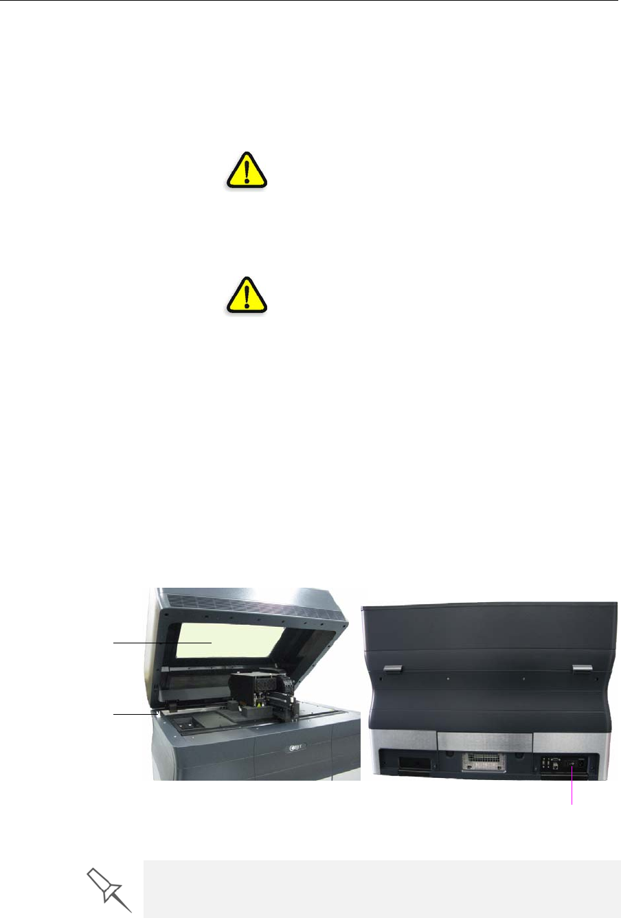
Safety Features
Alaris3‐DprintersaredesignedtocomplywithCEandFCCstandards.
Theyareequippedwiththefollowingsafetyfeatures:
Figure 2-1: Front and back views of the Alaris30 printer
Coverinterlock
switch ThepowersuppliedtotheUVlampandthe
motionmotorsisturnedoffwhenthecoveris
opened.
WARNING:Donotdefeat(override)the
interlockswitch.Doingsocouldresultin
seriouspersonalinjury.Iftheinterlockswitch
doesnotfunctioncorrectly,donotusethe
printer,andcontactyourserviceprovider.
Coverlock Thecoverislockedwhiletheprinteris
working.Itisreleasedwhentheprinterreverts
topauseorstopmode.
WARNING:Donotdefeat(override)the
safetylock.Doingsocouldresultinserious
personalinjury.Ifthesafetylockdoesnot
functioncorrectly,donotusetheprinter,and
contactyourserviceprovider.
UVscreenThetransparentsectionofthecoverblocks
harmfulUVradiation,allowingtheoperatorto
viewthemodelasitisbeingmade.
Circuitbreaker Thepowertotheprinteristurnedoffincaseof
electricalovercurrent.
Note: The circuit breaker is only accessible to
service personnel.
Groundedchassis Thechassisoftheprinterisgrounded,to
preventelectricalshock.
Note: The power outlet must be properly
grounded, in accordance with the local electric
code, to provide this protection.
UV screen
Cover interlock switch
Circuit breaker
If the Alaris 3-D printing system is not used as specified in this guide, the safety
features may not provide adequate protection.
DRAFT 4 - July 11, 2010
DOC-24000 Rev. A 2–3
Alaris30 User Guide
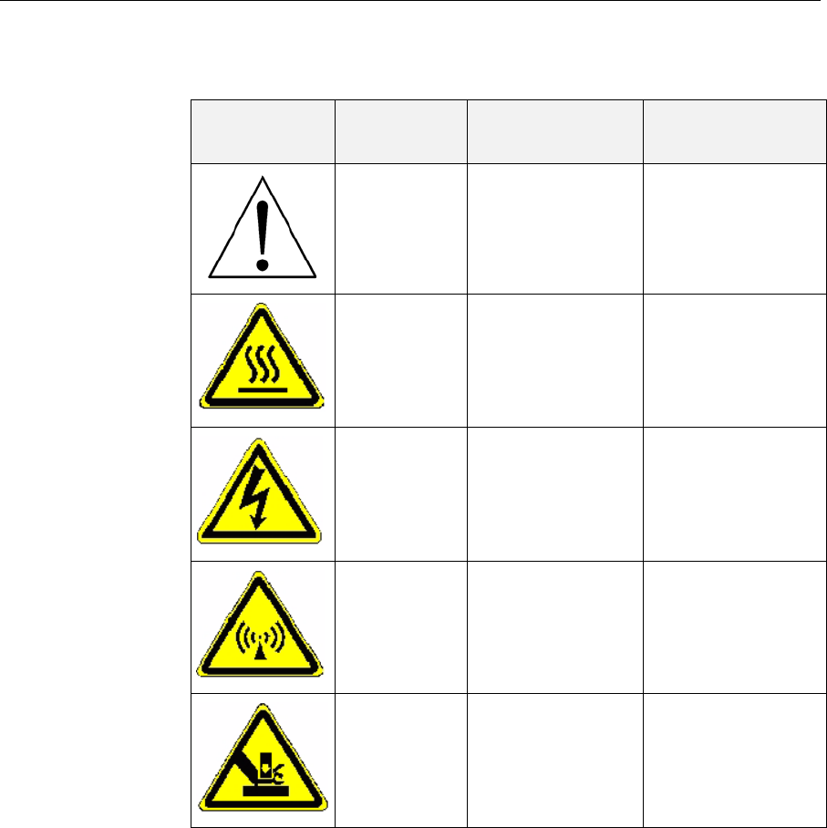
Symbols and Warning Labels
ThisfollowingtableliststhewarninglabelslocatedonorinAlarisprinters.
Warning
Symbol Meaning Location Comments
Hazard
(general) Onthenameplate
onthebackofthe
printer.
Readtheinstructions
inthisdocument
beforeoperatingthe
printer.
HotsurfaceOntheprint‐head
block. Riskofburns.Donot
touchthissurface
afterprinting.
HighvoltageNeartheUVlamp
connector.
Nearthepower‐
supplyenclosures.
Riskofelectricshock.
Ultraviolet
radiation NeartheUVlamp. Riskofinjuryfrom
ultravioletradiation.
Movingparts Ontopofthe
printingassembly. Riskofinjuryfrom
movingparts.
DRAFT 4 - July 11, 2010

Safety
2–4
DOC-24000 Rev. A
Safety Guidelines
Thefollowinggeneralguidelines,togetherwiththeinstructionsprovided
throughoutthisuserguide,ensureusersafetywhileoperatingand
maintainingtheAlarissystem.Ifthesystemisnotoperatedasspecified,
theuserʹssafetymaybecompromised!
Printer
Installation ¾InstallationandremovaloftheAlarisprintershouldonlybedoneby
qualifiedservicepersonnel.
¾Connecttheprintertotheelectricoutletusingapowercordthatis
safety‐certified.
¾Theelectricoutletshouldbeeasilyaccessible,neartheprinter.
¾Neverconnectthepowerplugtoanoutletthatdoesnothaveaground
(earth)wire,andneverdisconnecttheground.Doingsomayexpose
theoperatortoseriousdangerfromelectricshock.
¾Leaveaminimumof20centimetersbetweenventilationopeningsand
wallsorotherobjects.
Printer
Operation ¾TheAlarisprintershouldonlybeoperatedbypersonstrainedbyan
Objetcustomer‐supportrepresentative.
¾AllpersonneloperatingormaintainingtheAlarisprintershouldknow
thelocationoffirstaidandemergencyequipmentandhowtouseit.
Neverblockaccesstothisequipment!
¾Keepfingersandotherbodypartsclearoftheprintercoverwhen
closingit.
¾Neverattempttoopenthemaincoveroftheprinterwhileitisworking!
¾Neveroverridetheinterlocksafetyswitch!
¾Iftheinterlocksafetyswitcheverfails,donotusetheprinter.
¾Severalpartsoftheprinterremainextremelyhotevenafterithas
stoppedoperating.AvoidtouchingtheUVlampandtheprintblock.
UV Radiation ¾TheUVlampusedintheprinteremitsdangerousradiation.IftheUV
lampremainsonwhentheprintercoverisopen,donotstaredirectlyat
theUVlight.ShutdowntheprinterandcallyourObjetservice
provider.
Printer
Maintenance ¾Serviceoperationsshouldbeperformedonlybyqualifiedpersonnel
whohavebeeninstructedinrelevantsafetyprecautions.
¾Notifyco‐workersandthosewhohaveaccesstotheAlarissystem
beforebeginningnon‐routineandhazardouswork.
Report any potential dangers and safety-related accidents to your safety officer
or to other appropriate authorities.
DRAFT 4 - July 11, 2010

DOC-24000 Rev. A 2–5
Alaris30 User Guide
Model and
Support
Materials
Modelandsupportmaterialsaremadeofchemicalsubstances.Although
precautionsmustbetakenwhenhandlingthesematerialsdirectly,all
modelandsupportmaterialsusedbytheAlarissystemarehandledin
sealedcartridges.Normally,operatorsoftheAlarisprintershouldneverbe
directlyexposedtohazardousmaterials.Intheunlikelyeventofaleakor
spill,followtheinstructionsthatareincludedwiththeprinting‐material
cartridgeused.
¾Storecartridgesofmodelandsupportmaterialsindoors,inadryarea
withadequateventilation,between16‐27degreesCelsius(60‐81
degreesFahrenheit).Neverexposethemtoflames,heat,sparks,or
directsunlight.
¾Keepmodelandsupportmaterialsawayfromareaswherefoodand
drinkarestored,preparedandconsumed.
¾Uncuredprintingmaterialisconsideredahazardoussubstance,
requiringcertainprecautionswhendirectlyhandlingit.Topreventskin
irritation,wearneopreneornitrilegloves.Ifthereisanychancethat
modelandsupportmaterialsmightsplashintotheeyes,wearsafety
goggles.Prolongeddirectcontactwithprintingmaterialscancausean
allergicreaction.
¾WhenhandlingUV‐curedmodelsthatmaynotbecompletelycuredon
thesurface,commonlatexglovesareadequate.
¾Topreventrespiratoryirritation,ventilateareaswheremodeland
supportmaterialsareused.Theventilationsystemshouldtotally
replacetheairatleastfourtimesperhour.
¾Cleanupmodel‐materialandsupport‐materialspillswithdisposable
towelsorotherabsorbent,non‐reusablematerial,suchassawdustor
activatedcharcoal.Rinsethespillareawithdenaturedorisopropyl
alcohol(IPA),followedbysoapandwater.Disposeoftheabsorbent
materialinaccordancewithlocalregulations.
¾Donotwashcontaminatedclothingathome;clothingshouldbe
professionallylaundered.
¾Disposeofcontaminatedshoes,beltsandotherleatheritemsin
accordancewithanyapplicableregulations.Absorbedprinting
materialmayre‐exposetheuserwhentheseitemsareworn.
DRAFT 4 - July 11, 2010

Safety
2–6
DOC-24000 Rev. A
First Aid for Working with Printing Materials
Ingeneral,trytoavoiddirectcontactwithuncuredprintingmaterial.If
skinoreyescomeintocontactwithit,washtheareaimmediatelyand
thoroughlywithwater,andfollowthesefirst‐aidinstructions.
Contact with
Skin Ifuncuredprintingmaterialcomesincontactwithskin,washtheaffected
areaimmediatelyandthoroughlywithsoapandcoolwater,thenremove
contaminatedclothing.Payparticularattentiontoflushingthehair,ears,
noseandotherpartsofthebodythatarenoteasilycleaned.
¾Usecoolwatertopreventskinporesfromopening,sothattheliquid
materialdoesnoteasilypenetratetheskin.
¾Donotusesolventstocleanskin.
¾Iflargeareasofskinhavebeenexposed,orifprolongedcontactresults
inblisters,seekmedicalattention.Inanycase,ifirritationpersists,seek
medicalattention.
¾Avoidtheaccidentaltransferofprintingmaterialfromthehandsto
otherareasofthebody,especiallytotheeyes.
¾Ifprotectivecreamwasused,donotreapplyituntiltheskinhasbeen
completelycleansed.
Contact with
Eyes Ifuncuredprintingmaterialcomesincontactwiththeeyes,flush
immediatelywithlargeamountsofwaterfor15minutesandseekmedical
attention.
¾Avoidsunlight,fluorescentlight,andothersourcesofultraviolet
radiation.
Thewearingofcontactlenseswhenhandlingliquidprintingmaterialsis
notrecommended.Iftheliquidsplashesintotheeyeswhencontactlenses
areworn,immediatelyremovethelensesandflushtheeyeswithwater.
¾Cleananddisinfectthecontaminatedlenses.
¾Donotwearcontactlensesuntileyeirritationdisappears.
Ingestion Ifprintingmaterialisswallowed,refertotheinstructionsincludedwiththe
cartridge.Seekmedicalattentionimmediately.
Inhalation Vaporsfromprintingmaterialscanbeirritatingtotherespiratorysystem.
Ifrespiratoryirritationoccurs,exposethevictimtofreshairimmediately.
¾Ifthevictimhasstoppedbreathing,performartificialrespirationor
cardiopulmonaryresuscitation.
¾Seekmedicalattentionimmediately.
¾Keepthepatientwarmbutnothot.
¾Neverfeedanythingbymouthtoanunconsciousperson.
¾Oxygenshouldbeadministeredbyauthorizedpersonnelonly.
DRAFT 4 - July 11, 2010

DOC-24000 Rev. A 2–7
Alaris30 User Guide
Waste Disposal
Fullycuredprintedmodelscanbedisposedofasordinaryofficetrash.
However,specialcareisrequiredwhenhandlingprinterwaste.
¾WhenremovingthewastecontainerfromtheAlarisprinter,wear
neopreneornitrilegloves.
¾Topreventliquidwastefromsplashingintotheeyes,wearsafety
goggles.
¾LiquidwastefromtheAlarisprinterisclassifiedashazardous
industrialwaste.Therefore,printing‐materialwastemustbepackaged
anddisposedofinamannerthatpreventshumancontactwithitand
contaminationofwatersources.
¾Emptymodel‐materialandsupport‐materialcartridgescontainresidue
oftheircontents.Someleakageofthisresiduemayoccurthroughthe
brokencartridgeseal.Therefore,handleandstoreemptycartridges
withcare.
¾Donotattempttoreuseemptycartridges,anddonotpuncturethem.
¾Disposeofusedcartridgesandwastecontainersinaccordancewith
localregulations.
¾Discardcontaminatedclothing,shoes,emptycontainers,etc.,in
accordancewithanyapplicableregulations.
DRAFT 4 - July 11, 2010

Safety
2–8
DOC-24000 Rev. A
DRAFT 4 - July 11, 2010

DOC-24000 Rev. A 3–1
Introducing the Alaris 3-D
Printing System
WorkConfigurations .......................................................................... 2
SourceFiles........................................................................................... 3
STLFiles ................................................................................................. 3
SLCFiles ................................................................................................. 3
PrintingMaterials................................................................................ 4
AvailableMaterials ............................................................................... 4
Storage .................................................................................................... 4
ShelfLife................................................................................................. 5
ExposuretoLight.................................................................................. 5
SafetyConsiderations........................................................................... 5
Disposal .................................................................................................. 5
WorkEnvironment.............................................................................. 6
WorkstationRequirements ................................................................ 6
PreparingFilesforUsewithAlaris3‐DPrintingSystems............ 7
ConvertingCADFilestoSTLFormat ................................................ 7
ConvertingFilestoSLCFormat.......................................................... 7
ObjetSoftware...................................................................................... 8
DRAFT 4 - July 11, 2010
Introducing the Alaris 3-D Printing System
3–2
DOC-24000 Rev. A
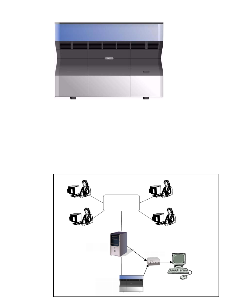
Figure 3-1: The Alaris30 3-D Printer
Work Configurations
TheAlaris303‐Dprintingsystemcanbesetupasasingle‐stationsystemor
asamulti‐stationsystem.Whenconnectedtoalocalcomputernetwork,the
systemcanservemultipleusers.Insuchconfigurations,eachuser
workstation(client)preparesfileswithObjetStudiosoftwarefor
production.Aserver(host),typicallynexttothe3‐Dprinter,actsasajob
managerthatsendsproductionjobstotheprinterforproduction.
Figure 3‐2showstheAlaris30printersetupinamulti‐clientconfiguration.
Figure 3-2: Multi-client network configuration
WheninstallingtheObjetsoftware,youchoosewhethertoinstallitasa
clientstationorasamasterstation(serverorstandalonestation).
Alaris server KVM switch
Client workstations
Printer
workstation
Alaris printer
DRAFT 4 - July 11, 2010

DOC-24000 Rev. A 3–3
Alaris30 User Guide
TheObjetsoftwarearrangesthejobsitreceivesaccordingtotheirpriorities,
model‐materialtype,andotherfactors.Inmulti‐workstation
configurations,theoperatoroftheserver—typicallytheproduction
administrator—hastotalcontroloverthejobssenttothe3‐Dprinter,and
canprioritizeanddeletejobs,reviewjobhistoryandreprintajob,andso
on.
Source Files
Alaris3‐Dprintingsystemsproducethree‐dimensionalmodelsdesigned
withmost3‐DCADtoolsandwithotherjob‐specific3‐Dapplications.
Alarissystemsaccept:
•STLfiles
•SLCfiles
Alarissystemsfeaturethecapabilityofproducingbothtypesofmodelfiles
simultaneously.
STL Files STLisshortforStandardTriangulationLanguage.Thislanguageviewsany
objectasacollectionofsurfaces,anddescribeseachsurfaceoftheobjectas
acollectionoftriangles.
Forexample,asquarecanbedescribedastwotriangles;acube(six
squares)as12triangles.Curvedsurfacesneedmoretrianglestodescribe
them.Thehigherthetolerance(forsmoothsurfaces),themoretrianglesare
needed.Theresultisthathigh‐qualityobjectdescriptionsmeanveryheavy
files.
MostCADsoftwarecanexportSTLfiles.TheAlarissystemutilizesthese
filesforbuildingmodels(rapidprototyping),andalsofordirectlymaking
moldsformass‐producingitems.
STLfilesareASCII(text)files.Thecontentofeachfilebeginswith“solid”
andendswith“end‐solid”(bothlowercase).Betweenthesekeywordsisa
listofthetrianglesthatdescribesthefacesofthesolidmodel.Eachtriangle
definesasinglenormalvectordirectedawayfromthesolid’ssurface,
followedbyitsX‐Y‐Zcoordinates.TheseareexpressedasCartesian
coordinatesandarefloating‐pointvalues.Thecoordinatesofalltriangles
shouldbepositiveandshouldfallwithinthevolumeofthemodel.
SLC Files SLCisshortforStereo‐LithographyContour.SLCfilesdescribetwo‐
dimensionalcontoursofthethree‐dimensionalmodels.Thesecontourlines
arepolylines.
SLCfilesareASCII(text)filesthatsavemodelsasaseriesofslices.This
meansthatmodelsbasedonSLCfilescannotbeorientated;onlytheirscale
(size)andpositiononthebuildtraycanbecontrolled.Forthisreason,the
model’sorientationmustbesuitableforproductionbeforeitissavedasan
SLCfile.BecauseofthenatureofSLCfiles,theappearanceofmodelsin
ObjetStudiomaybedifferentthanthesolid‐objectimagesdisplayedfrom
STLfiles.
DRAFT 4 - July 11, 2010

Introducing the Alaris 3-D Printing System
3–4
DOC-24000 Rev. A
Printing Materials
Alarisprintersproducemodelsbyjettingthinlayersofprintingmaterials
onthebuildtray,untilthecompletemodelisformed.Twotypesofmaterial
areusedinthisprocess:
•Modelmaterial—whichmakesupthefinishedmodel
•Supportmaterial—whichfillsgapsandspacesinthemodelduring
printing,andisremovedafterprinting
Available
Materials TwomaterialtypesareavailableforproducingmodelswiththeAlaris30
printer—
•Vero
Materialsinthisgrouparesuitableforgeneralmodelmaking,andcome
inachoiceofcolor(white,blue,gray,andblack).Theyofferthe
followingfeatures:
thermo‐plasticssimulation(appearanceandfeel)
highdimensionalstability(especiallywithVeroGray™)
excellentdetailandsurfacequality
•Durus
CurrentlyavailableasDurusWhite™withthefollowingfeatures:
polypropylenesimulation(appearanceandfeel)
enhancedtoughnessandflexibility—suitableforreusablecontainers
andothersnap‐fitapplications
Forup‐to‐dateinformationaboutObjetprintingmaterialsandtheir
properties,gotowww.objet.com/Materials.
Storage MaterialsusedforprintingmodelswithAlarisprintersaremadeofresins,
whicharecomposedofreactivemonomersandoligomers.Although
printingmaterialsaresuppliedinsealed,UV‐proofcartridges,caremustbe
takenwhenstoringandhandlingthem.Followtheseguidelinestoprotect
operatorsandtheenvironment,andtoensureoptimumresults.
•Toensureproductstability,donotallowthesematerialstocomeinto
contactwithmetal.Plasticsmadefrommonomer‐solublesubstances
(suchaspolystyreneorpolyvinylchloride)arenotsuitableforstoring
Objetprintingmaterials.
•Whennotinuse,keepmaterialcartridgestightlysealedtoprevent
contamination,theeffectsofexposuretoUVradiation,andaccidental
spillage.
•Storematerialcartridgesindoors,inadryareawithadequate
ventilation,between16–27degreesCelsius(60–81degreesFahrenheit).
Ifexposedtoheatorflames,cartridgesmayburstorignite.
•Signsofprematurepolymerizationinmaterialcartridgesmayinclude
bulging,leaking,theemissionofheat,andunusualodor.Exposureto
heatcancauseresintogelinthecartridge.
•Makesurethatmaterialcartridgesarestoredinaccordancewithall
localregulationsandotherapplicablerequirements.
DRAFT 4 - July 11, 2010

DOC-24000 Rev. A 3–5
Alaris30 User Guide
Shelf Life Materialsusedforproducingmodelshavealimitedshelflife.Theexpiry
dateonthelabelisvalidwhenproperlystoredinanundamaged,
unopenedcartridge.Alwaysrotateyourstock,sothatthecartridgewith
theearliestdateisusedfirst.
Exposure to
Light Ifprintingmaterialsarenotintheirsealedcartridges,makesuretoshield
themfromsunlightandothersourcesofUVradiation,suchasfluorescent
andmercury‐vaporlights.ExposuretoUVradiationcausesanincreasein
viscosityand,eventually,solidification.
Safety
Considerations Beforebeingcured,resinsarehazardousmaterials.Topreventpossible
healthhazards,followtheseprecautionsregardingprintingmaterials:
•Donotexposetoflames,heatorsparks.
•Preventcontactwithskinandeyes.
•Ventilateareaswheretheyarehandled.
•Keepthemseparatefromfoodanddrink.
Curedplasticparts,however,aresafe.Theycanbehandledandstored
withoutprecautions.
Disposal DisposeofcartridgesofObjetmodelandsupportmaterialinaccordance
withallapplicablelawsandregulations.Ifnecessary,thecartridgescanbe
disassembledforrecycling.
You can find more safety information about resins in “Safety Guidelines” on
page 2-4, and “First Aid for Working with Printing Materials” on page 2-6.
DRAFT 4 - July 11, 2010

Introducing the Alaris 3-D Printing System
3–6
DOC-24000 Rev. A
Work Environment
Extremeheatandhumidityconditionscanadverselyaffecttheoperationof
theAlaris3‐Dprinter.Therefore,itisrecommendedthatyouuse
ventilationorair‐conditioningsystems,ifnecessary,tokeeptheworkarea
withinthefollowingranges:
•18°–25°C(64°–77°F)
•30%–70%relativehumidity
Workstation Requirements
TheminimumrequirementsforcomputercomponentsusedwithObjet3‐D
printersoftwarearelistedinthefollowingtable.
Server/
Stand-alone Station Client Workstation
Processor Pentium4,3.0GHz,
512KBcachememory(min.) Pentium4,3.0GHz(min.)
Operating System MicrosoftWindowsXP MicrosoftWindowsXP
Graphics Card SupportingopenGL,
with256MBofmemory SupportingopenGL,
with256MBofmemory
RAM 4GB(min.) 2GB(min.)
CD Drive IDECDROM IDECDROM
Hard-Disk Drive 40GB(min.) 40GB(min.)
Network Adaptor
Cards
LANTCP/IP(2) LANTCP/IP(1)
Ethernet Cables •Straight‐throughcable(1)
•Crossovercable(1,supplied) Straight‐throughcable(1)
DRAFT 4 - July 11, 2010

DOC-24000 Rev. A 3–7
Alaris30 User Guide
Preparing Files for Use with Alaris 3-D Printing Systems
BeforeusingfileswithAlaris3‐Dprintingsystems,youmustconvertthem
inyourCADprogramtoeitherSTLfilesorSLCfiles.(Foranexplanationof
thesefileformats,see“SourceFiles”onpage 3‐3.)
Afterconvertingthemodelfiles,itisrecommendedthatyoucheckthemfor
defectsinanSTL‐repairapplication(suchasMagics,byMaterialise)before
openingtheminObjetStudioandproducingthemodel.
Converting
CAD Files to
STL Format
Thisproceduremayvaryslightly,dependingontheCADsoftwareused,
butthefollowinginstructionsgenerallyapply.
To convert a file to STL format (in a CAD program):
1. FromtheFilemenu,selectSave As.
2. IntheSave Asdialogbox,opentheSave As Typepull‐downmenuand
select*.STL.
3. ClickOptionsandsetthefollowingparameters:
•TotalQuality—approximately0.1mm(deviationtolerance/linear‐
dimensiontolerance)
•DetailQuality—approximately4°(angletolerance)
Note: Lowering these values produces more accurate models, but
results in larger files and longer loading and processing times. For this
reason, it is generally not recommended that you use lower values.
4. Inthefileformatoption,choosebinaryorASCII.(Bothbinaryand
ASCIIformatscanbeusedinObjetStudio.However,binaryfilesare
smaller,sothisoptionisrecommended.)
5. ClickOKorSave.
Converting
Files to SLC
Format
WhenconvertingfilestoSLCformat,itisrecommendedthatyousetalayer
thicknessof15microns(0.015mm).SinceSLCfilescannotbeorientatedin
ObjetStudio,itisimportantthatmodelsareproperlyorientatedbefore
beingsavedasSLCfiles.Considerationsforsuitablemodelorientationare
explainedin“ModelOrientation”onpage 5‐10.
DRAFT 4 - July 11, 2010

Introducing the Alaris 3-D Printing System
3–8
DOC-24000 Rev. A
Objet Software
ObjetsoftwarefortheAlaris3‐Dprintingsystemconsistsoftwo
applications:
•ObjetStudio
•JobManager
Objet Studio
WithObjetStudio,youpreparesourcefilesforproductioninAlaris3‐D
printers.ObjetStudiooffersyouawidevarietyoffile‐preparationoptions,
butalwaysconsistsofthefollowingbasicprocedure:
1. Insertingoneormoreobjectsonthebuildtray
2. Positioningtheobject(s)onthetray
3. Configuringobjectandtrayparameters
4. Savingthetrayconfigurationasanobjtf(ObjetTrayFormat)file
5. SendingtheobjtffiletotheAlaris3‐Dprinterforproduction
UsingObjetStudiotoperformthesetasksisdescribedindetailinchapter 5,
“UsingObjetStudio.”
Job Manager
TheJobManagerapplicationisdifferentforclientworkstationsandforthe
computerconnecteddirectlytotheAlaris3‐Dprinter.
•JobManagerinstalledonthedirectly‐connectedcomputer(server)
displaysthequeueandstatusforalljobssenttothe3‐Dprinterbythe
clientcomputersonthenetwork,andallowseditingandmanipulation
ofalljobs.
•JobManagerinstalledonclientcomputersdisplaysthequeueand
statusonlyforjobssenttothe3‐Dprinterserverfromthatcomputer,
andallowstheusertoeditonlythesejobs.
JobManagerisdescribedindetailinchapter6,“UsingJobManager.”
Client computers can be connected, via the local network, to different Alaris
3-D printers, but only to one at a time. The client Job Manager displays the
status of the 3-D printer to which the client is currently connected.
DRAFT 4 - July 11, 2010

Installing Objet Software
4–2
DOC-24000 Rev. A
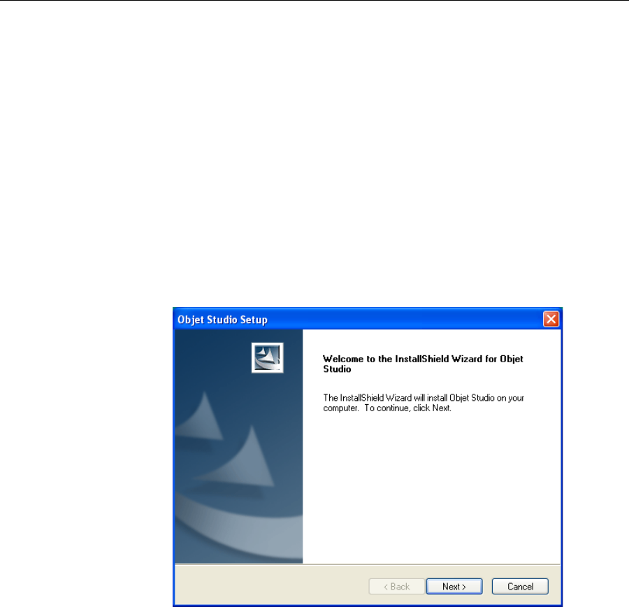
How to Install Software for the Alaris 3-D Printing System
TheObjetStudiosetupwizardguidesyouwheninstallingtheObjet
software.Duringinstallation,youmustchoosetoinstalleithertheserver
(“host”)applicationortheclientapplication.
To install Objet software:
1. InserttheObjetStudioCDintothediskdrive.
2. Right‐clicktheStartbuttonandselectExplore(oruseanyothermethod
fordisplayingfilesonthecomputer).
3. OpentheCD‐drivefolderandselectSetup.
Toruntheinstallationwizard,youmustaccepttheObjetStudiolicense
agreement.Afterreadingitsterms,clickYestocontinue,orNotoclose
thewizard.
IfyouclickYes,thefollowingscreenshouldappear.
Figure 4-1:Objet Setup—installation wizard Welcome screen
DRAFT 4 - July 11, 2010
DOC-24000 Rev. A 4–3
Alaris30 User Guide
4. ClickNexttobegininstallation.
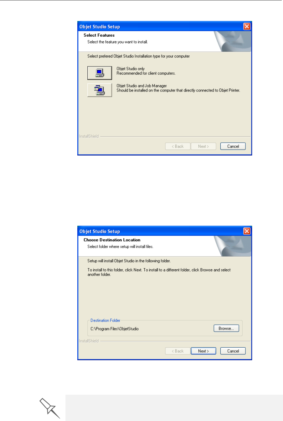
Figure 4-2: Objet Setup—Select Components screen
5. WhentheSelectComponentsscreenappears,selectoneofthe
installationoptions,thenclickNext.
•SelectObjet Studio onlyforclientworkstations
•SelectObjet Studio and Job Managerfortheserver(host)stationand
forastandalonestation—thatis,thecomputerdirectlyconnectedto
theAlarisprinter.
Figure 4-3: Objet Setup—Choose Destination Location screen
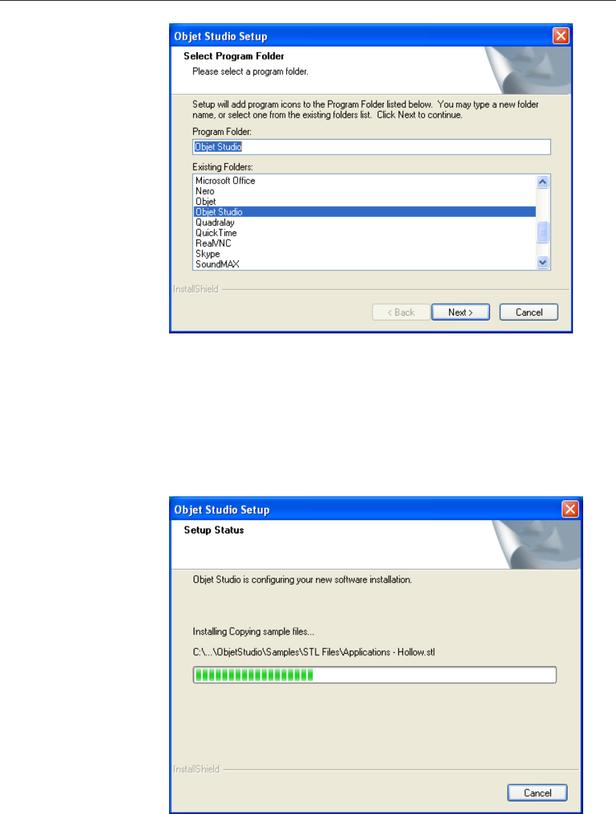
6. IntheChooseDestinationLocationscreen,verifythedestinationfolder
andclickNext.
It is recommended that you do not change the default destination folder.
DRAFT 4 - July 11, 2010
Installing Objet Software
4–4
DOC-24000 Rev. A
Figure 4-4: Objet Setup—Select Program Folder screen
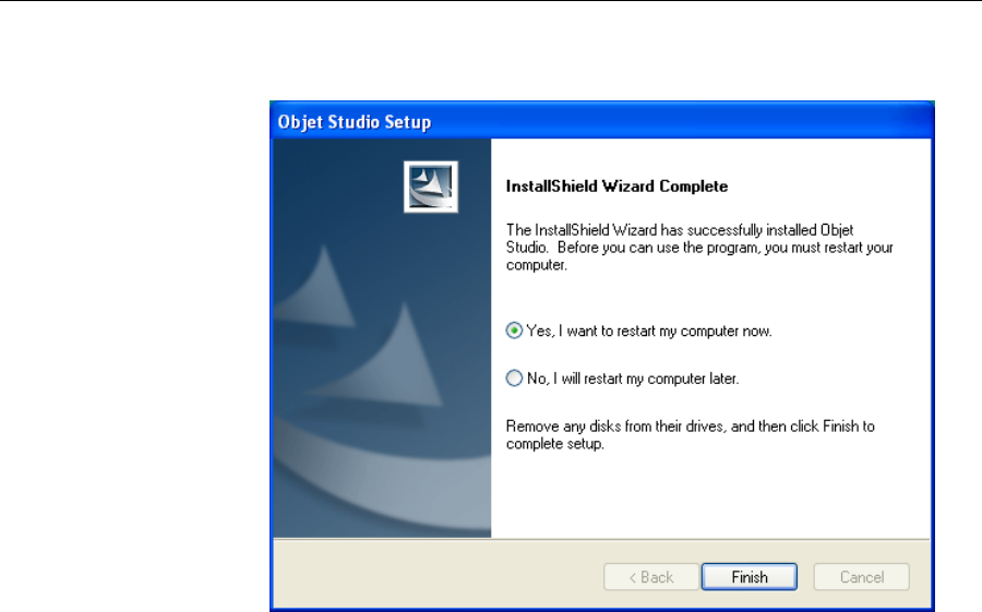
7. IntheSelectProgramFolderscreen,verifythepre‐selectedfolderin
whichtheObjetStudioiconswillbeinstalled.
•Toinstalltheiconsinanotherprogramfolder,selectit.
•Tocontinue,clickNext.
InstallationbeginsandtheSetupStatusscreenappears,showingthe
progressoftheinstallationprocess.
Figure 4-5: Objet Setup—Setup Status screen
DRAFT 4 - July 11, 2010
DOC-24000 Rev. A 4–5
Alaris30 User Guide
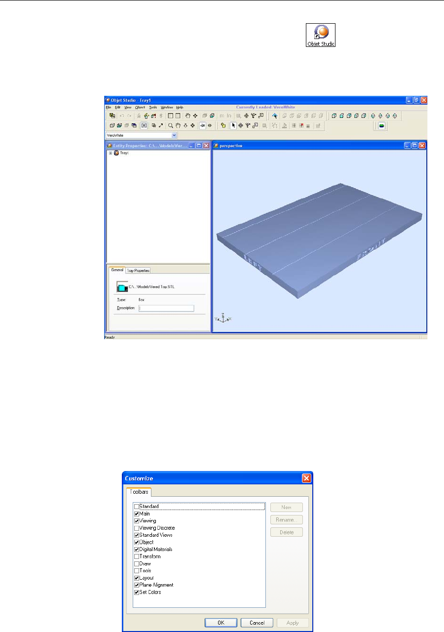
WhentheObjetprograminstallationiscomplete,thefinalInstallShield
Wizardscreenappears.
Figure 4-6: Objet Setup—final wizard screen
Tocompletethesoftwareinstallation,youmustrestartthecomputer.
Youcandosonoworatanothertime.
8. Selecteither“Yes…”or“No…”andclickFinish.
MakesuretoremovetheCDfromthediskdrivebeforerestartingthe
computer.
Theinstallationprocessendswhentheappropriateicon(s)appearonthe
computerdesktop:
•ObjetStudio
•JobManager(forserversandstandalonestations)
•StopJobManager(forserversandstandalonestations)
DRAFT 4 - July 11, 2010

Installing Objet Software
4–6
DOC-24000 Rev. A
DRAFT 4 - July 11, 2010

DOC-24000 Rev. A 5–1
Using Objet Studio
OpeningObjetStudio ......................................................................... 2
Toolbars .................................................................................................. 2
PreparingModelsforProduction ..................................................... 3
OpeningSTL&SLCFiles .................................................................... 3
CopyingandPastingObjects .............................................................. 5
SelectingObjects.................................................................................... 5
ArrangingtheObjetStudioScreen................................................... 6
PositioningObjectsontheBuildTray .............................................. 8
AutomaticPositioning.......................................................................... 8
ManualPositioning............................................................................... 9
ModelOrientation............................................................................. 10
ManipulatingObjectsontheBuildTray........................................ 11
ObjectPositionontheZ‐Axis............................................................ 11
RepositioningObjects......................................................................... 12
ValidObjectPlacement...................................................................... 14
UsingaGridtoPositionObjects ....................................................... 14
ChanginganObject’sOrientation..................................................... 15
FreezinganObject’sOrientation....................................................... 16
SurfaceFinish....................................................................................... 16
DefaultObjectProperties ................................................................... 17
DisplayOptions................................................................................. 18
DisplayColors ..................................................................................... 19
DisplayingLargeFiles........................................................................ 20
TrayViewingOptions ........................................................................ 21
HandlingCompletedTrays ............................................................. 23
TrayValidation .................................................................................... 23
ProductionEstimates.......................................................................... 24
SavingtheTrayFile............................................................................. 24
PrintingtheTrayFile .......................................................................... 24
AdditionalObjetStudioFeatures ................................................... 26
DividingObjects.................................................................................. 26
ChoosingtheSupportStrength......................................................... 26
“Smartcast”—FillingModelswithSupportMaterial .................... 27
DisplayingtheCrossSectionofObjects .......................................... 28
PrintingtheScreenDisplayonPaper .............................................. 29
SavingtheScreenDisplayasanImage File .................................... 29
ExportingandImportingObjetBuildTrays ................................... 29
Advanced‐ModeFeatures................................................................ 30
SaveTrayAs…..................................................................................... 31
ConfiguringtheGLDriver ................................................................ 32
DRAFT 4 - July 11, 2010
Using Objet Studio
5–2
DOC-24000 Rev. A
Opening Objet Studio
AfteryouinstallObjetStudio,alaunchiconappearsonthe
Windowsdesktop.Opentheapplicationbydouble‐clickingthisicon,orby
selectingObjetStudiofromtheStart>Programsmenu.
ObjetStudioopens,displayinganemptybuildtray.
Figure 5-1: Objet Studio opening screen
Toolbars Theiconsshowninthischapterareavailableonlywhenrelevanttoolbars
aredisplayed.Youcancontrolthetoolbarsdisplayedatanytime,andyou
canre‐arrangethemonthescreen.
To customize the toolbars displayed in Objet Studio:
1. FromtheViewmenu,selectToolbars.
2. IntheCustomizedialogbox,selectthetoolbarsyouwishtodisplay,and
clickOK.
Figure 5-2: Toolbar selection dialog box
3. ClickanddragthetoolbarstopositionthemasyouwishontheObjet
Studioscreen.
DRAFT 4 - July 11, 2010
DOC-24000 Rev. A 5–3
Alaris30 User Guide
Preparing Models for Production
Toproducemodels,youmustopenoneormorefilesinObjetStudioand
positiontheobjectsonthebuildtray.Youcanplaceobjectsonthebuildtray
intwoways:
•byinsertingindividualstlorslcfiles
•bypastingobjectsthatyoucopiedtotheWindowsclipboard
Ifyouknowwhattypeofmodelmaterialwillbeusedtoproducethe
models,makesureitisselectedfromthematerialdrop‐downmenu.
Figure 5-3: Model material selection toolbar
Note: It is not necessary to select the model material now, but it is
recommended—each type of material has unique characteristics
that may affect the valid positioning of objects on the build tray.
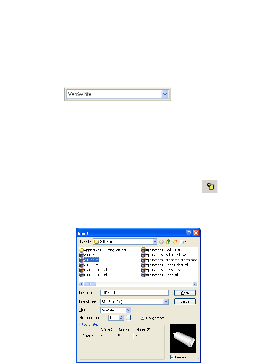
Opening STL
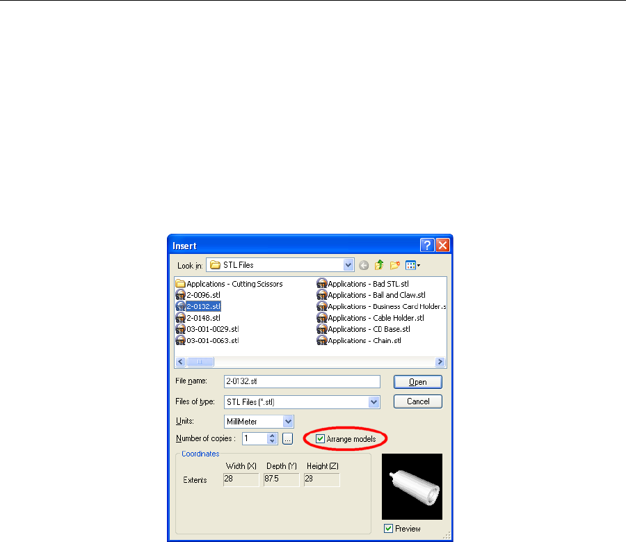
& SLC Files To place an object on the build tray:
1. OpentheInsertdialogbox—
•FromtheObjectmenu,selectInsert.
or—
•Onthetoolbar,clicktheInsertModelicon.
or—
•Right‐clickonthebuildtray,andselectInsert.
TheInsertdialogboxappears.
Figure 5-4: Insert dialog box
2. IntheLookinfield,displaytheappropriatefolder.
3. IntheFilesoftypefield,selectthefiletypestodisplay(stl,slc).
4. Selectthedesiredfile,andmakesurethatitappearsintheFilename
field.
DRAFT 4 - July 11, 2010
Using Objet Studio
5–4
DOC-24000 Rev. A
IfthePreviewcheckboxisselected,theobjectisdisplayedinthedialog
box,asshowninfigure 5‐4.
5. Selectanyofthefollowingoptions,asrequired:
•Units—Choosemillimetersorinchesfortheobject’sunitsofmeasure.
•Number of copies—Choosehowmanycopiesofthisobjecttoplace
onthebuildtray.
•Arrange models—Selectthischeckboxtoautomaticallyposition
objectsonthebuildtrayforefficientmodelbuilding.
Note: The 3-D file contains the object's proportions, but not its units of
measure. Therefore, make sure to correctly select either millimeters or
inches when inserting an object. Otherwise, the size of the object on the
build tray will be either much too large or much too small.
6. ClickOpen.
ObjetStudioplacestheobjectonthebuildtray,andinthelistinthe
hierarchypane.
Figure 5-5: Default screen layout
Youcanplaceadditionalobjectsonthebuildtraybyrepeatingthis
procedure.
The Extents values displayed at the bottom of the dialog box represent the
maximum dimensions of the object on each axis. These dimensions
correspond to the virtual “bounding box” surrounding the object (see
figure 5-24 on page 5-19).
Hierarchy
pane
Build tray
Object
properties
DRAFT 4 - July 11, 2010
DOC-24000 Rev. A 5–5
Alaris30 User Guide
Copying and
Pasting
Objects
Ifyouneedtoduplicateobjectsonthebuildtray,youcan,ofcourse,insert
thesameobjectfromitsfilemorethanonce.Aneasierway,however,isto
copyandpastetheobject.Youcancopyobjectsfromthebuildtrayorthe
hierarchypane.TheobjectscopiedremainintheWindowsclipboarduntil
youpastethemontothebuildtray.
Youcanalsocopyobjectsfromonetrayandpastethemontoanother,inthe
samewayasyoucopytextfromonedocumentandpasteitintoanother
one.However,ObjetStudioallowsonlyonetraytobeopenatatime.For
eachbuildtrayyouneedtoworkwith(atthesametime),youmustopena
separateObjetStudiowindow,byrunningtheapplicationagain(fromthe
WindowsStartmenu).
YouperformtheCopyandPastecommandsasinotherWindows
applications:
•fromtheEditmenu,onthemaintoolbar
•fromtheright‐clickcontextmenu
•byusingkeyboardshortcuts(Ctrl+CandCtrl+V,respectively)
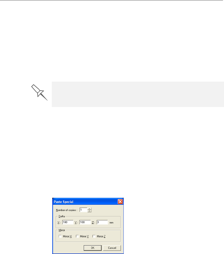
ThePasteSpecialcommand(intheEditmenu)enablesyoutoplace
duplicateobjectsevenmoreefficiently:
•Youcanspecifythenumberofduplicatestoplaceonthebuildtrayat
once.
•Youcansetthedistance,oneachaxis,betweentheduplicateobjects.
•Youcanplacemirrorimagesoftheoriginalobject.
Figure 5-6: Paste Special dialog box
Selecting
Objects Tomanipulateanobjectonthebuildtrayorassigncharacteristicstoit
(surfacefinish,forexample),youmustfirstselecttheobject.Youselectan
objectbyclickingit,eitheronthetrayorinthetrayhierarchypane.Its
imageonthebuildtraychangescolor(tolightblue,bydefault)andits
nameishighlightedinthetrayhierarchypane.Youcanselectmultiple
objectsbypressingtheCtrlorShiftkeyswhileclickingadditionalobjects.
Having multiple Objet Studio windows open can be convenient when you
need to manipulate or configure objects before inserting them in your
production build tray. Copying and pasting also allows you to utilize objects
already configured on previously-used build trays for newer projects.
DRAFT 4 - July 11, 2010
Using Objet Studio
5–6
DOC-24000 Rev. A
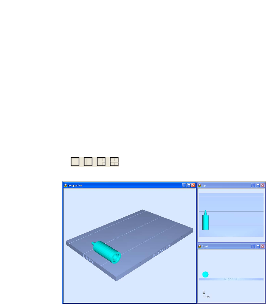
Arranging the Objet Studio Screen
Thedefaultscreenlayoutdisplaystheperspectiveviewofthebuildtrayand
thetrayhierarchypane,whichliststheelementsplacedonthetray(see
figure 5‐5onpage 5‐4).Youcanviewmodelsfromdifferentanglesby
changingthescreenlayout.
To change the Objet Studio screen layout:
¾FromtheViewmenu,selectLayout,thenthedesirednumberofbuild‐
trayviews.
2 Viewsisthedefaultscreenlayout,alreadydisplayed(seefigure 5‐5
onpage 5‐4).
Bydefault,theobjectpropertiesdialogboxisalsodisplayed.
3 Viewsaddstopandfrontviewstothedefaultscreenlayout(see
figure 5‐8,below).
4 Viewsdisplaystop,frontandrightviews(seefigure 5‐9).
1 Viewexpandstheperspectiveviewtofillthescreen(seefigure 5‐10).
¾Youcanalsochangethescreenlayoutwithtoolbaricons.
Figure 5-7: Screen layout icons
Figure 5-8: 3-view screen layout
DRAFT 4 - July 11, 2010
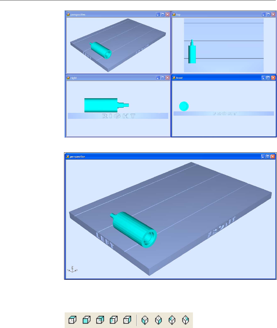
DOC-24000 Rev. A 5–7
Alaris30 User Guide
Figure 5-9: 4-view screen layout
Figure 5-10: 1-view screen layout
Youcanchangetheperspectiveoftheactiveviewingpanebyclickingany
ofthenineviewingicons.
Figure 5-11: Viewing-pane perspective icons
DRAFT 4 - July 11, 2010
Using Objet Studio
5–8
DOC-24000 Rev. A
Positioning Objects on the Build Tray
Toproducemodelsefficientlyandwiththerequiredfinish,itisimportant
tocarefullypositionobjectsonthebuildtray.ObjetStudiofeaturesthe
automaticpositioningofobjects.However,youshouldchecktomakesure
thattheobjectsareorientatedlogicallyforyourneeds,accordingthe
considerationsexplainedin“ModelOrientation”onpage 5‐10.
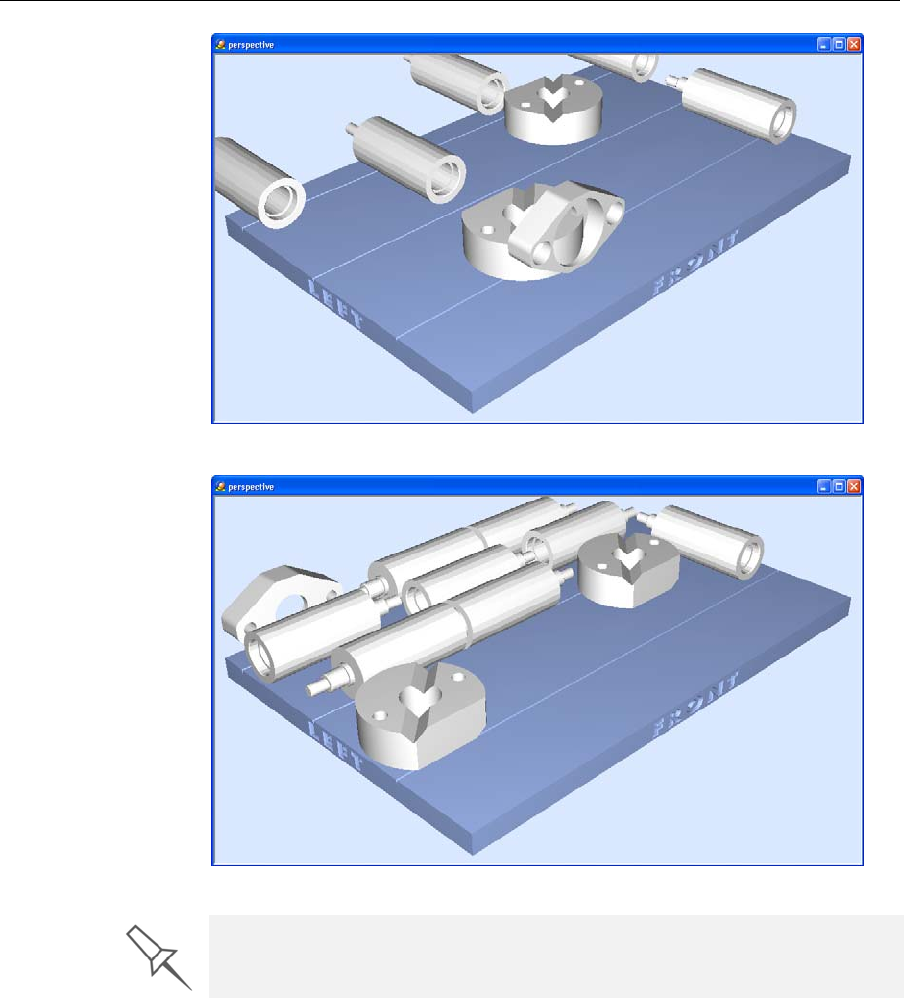
Automatic
Positioning TherearetwowaystohaveObjetStudiopositiontheitemsonthebuild
tray.
•Anytimeyouinsertanobjectontothebuildtray,selectArrange models
intheInsertdialogbox.
Figure 5-12: Arrange models option in the Insert dialog box
WhenyouclickOpen,ObjetStudioinsertsthenewobjectandarranges
alloftheobjectsonthebuildtray.
•Afterplacingseveralobjectsonthebuildtray,selectTools > Automatic
Placement.
Theeffectsofautomaticplacementareshowninfigures5‐13and5‐14.
DRAFT 4 - July 11, 2010
DOC-24000 Rev. A 5–9
Alaris30 User Guide
Figure 5-13: Tray before objects are properly arranged
Figure 5-14: Tray after objects have been automatically arranged
Manual
Positioning Youcanmanuallypositionobjectsonthebuildtray—eveniftheywere
insertedusingautomaticplacement(withtheArrangemodelsoption
selectedintheInsertdialogbox).Considerationsforpositioningobjectsare
reviewedin“ModelOrientation”onpage 5‐10.Toolsforchangingthe
positionofobjectsaredescribedin“RepositioningObjects”onpage 5‐12.
Because of the unique characteristics of each type of modeling material, it
is recommended that you select the material before inserting objects on the
tray with automatic positioning or running Automatic Placement.
DRAFT 4 - July 11, 2010

Using Objet Studio
5–10
DOC-24000 Rev. A
Model Orientation
Theorientationofmodelsonthebuildtrayaffectshowquicklyand
efficientlytheywillbeproducedbythe3‐Dprinter,whereandhowmuch
supportmaterialisused,andwhetherornotmodelpartswillhaveagloss
finish.Therefore,youshouldconsideravarietyoffactorswhendeciding
howtoplacemodelsonthetray,usingthefollowingpositioningrules.
X-Y-Z Rule
Thisruleconsidersamodelʹsouterdimensions.
¾SincetheprintheadsmovebackandforthalongtheX‐axis,theprinting
timealongthisaxisisrelativelyshort,comparedtoprintingtimealong
theY‐axisandZ‐axis.Fromthispointofview,itisadvisabletoplacethe
objectʹslongestdimensionalongtheX‐axis.
¾Sincemodelsarebuiltup,ontheZ‐axis,in30‐micronlayers,itisvery
time‐consumingtoprintatallobject.Fromthispointofview,itis
advisabletoplacetheobjectʹssmallestdimensionalongtheZ‐axis.
¾Sincetheprintheadsmeasureabout2inches(5centimeters)ontheY‐
axis,modelsmeasuringlessthanthis(ontheY‐axis)areprintedinone
pass.Fromthispointofview,itisadvisabletoplacetheobjectʹs
intermediatedimensionalongtheY‐axis.
Tall-Left Rule
Thisruleconsidersmodelswhere,afterbeingorientatedonthebuildtray
accordingtootherconsiderations,onesideistallerthantheother.
¾SincetheprintheadsmovealongtheX‐axisfromlefttoright,taller
sectionsontherightrequiretheprintheadstoscanunnecessarilyfrom
theleftuntilreachingthem.If,ontheotherhand,thetallersectionsare
positionedontheleftofthetray,theprintheadsonlyhavetoscanthe
modeluntilprintingthesesections—oncethelowerpartshavebeen
completed.Therefore,youshouldpositionthetallersideofthemodel,
whenpossible,ontheleft.
Recess-Up Rule
Thisruleconsidersmodelscontainingsurfacerecesses.
¾Recessesinthesurface(likehollows,drillholes,etc.)should,when
possible,bepositionedface‐up.
Fine-Surface Rule
Thisruleconsidersmodelsthathaveonesideonwhichtherearefine
details(likethekeypadsideofatelephone).
¾Thesideofthemodelcontainingfinedetailsshould,whenpossible,be
positionedface‐up.Thisresultsinasmoothfinish.
Avoid Support-Material Rule
Thisruleconsidersmodelsthathavelargeholesorhollows,openonat
leastoneside(likeapipeoracontainer).
¾Itmaybeadvantageoustoprintamodelstandingup,sosupport
materialdoesnotfillthehollow,eventhoughprintingthemodellying
downwouldbemuchfaster.
The following rules are based on the fact that support material is not
required on the top of the printed model.
DRAFT 4 - July 11, 2010
DOC-24000 Rev. A 5–11
Alaris30 User Guide
Manipulating Objects on the Build Tray
Object Position
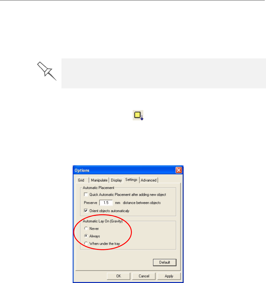
on the Z-Axis Whenyouuseautomaticpositioningtoarrangeobjectsonthebuildtray
(see“A u t o m a t i c Positioning”onpage 5‐8),theobjectsarepositioned
directlyonthetray.Ifyoudonotinsertobjectswithautomaticpositioning,
theyoftenappeareitheraboveorbelowthetray.
To position objects directly on the tray:
1. Selecttheobject.
2. ClicktheLayOnicon.
or—
FromtheObjectmenu,selectLay On.
To ensure that objects are always directly positioned on the tray:
1. FromtheToolsmenu,selectOptions,anddisplaytheSettingstab.
Figure 5-15:Options dialog box, Settings tab
2. IntheAutomaticLayOn(Gravity)section,selectAlways.(Thisisthe
defaultsetting.)
Other Z-axis options (in the Automatic Lay On section):
•When under the tray—Thedisplayofobjectsthatarebelowthebuild
trayisautomaticallychangedsothattheobjectisattraylevel.
•Never—Thedisplayofobjectsthatareaboveorbelowthebuildtrayis
notchanged.
In practice, the Alaris system prints all models on the build tray on a one-
millimeter bed of support material. The importance of positioning objects
directly on the build tray with Objet Studio is to correctly display the objects
on the screen.
DRAFT 4 - July 11, 2010
Using Objet Studio
5–12
DOC-24000 Rev. A
Repositioning
Objects Youcanselectandmanipulateobjectsonthebuildtrayafterselectingthe
followingiconsormenuoptions.
Afterusingtheserepositioningiconsonce,theyaredisabled,unlessyou
firstclicktheStickyModeicon.Afterclickingthisicon,therepositioning
iconusedremainsactiveuntilyouclicktheStickyModeiconagainto
releaseit.
Anotherwayofrepositioningobjectsonthebuildtrayisbyusingtheicons
ontheTransformtoolbarthatnudgetheselectedobjectindifferentways.
Viewing Object Properties
Afteryoumanuallymanipulateanobjectwiththemouse,itsnew
propertiesaredisplayedintheTransformtaboftheobjectpropertiesdialog
box.
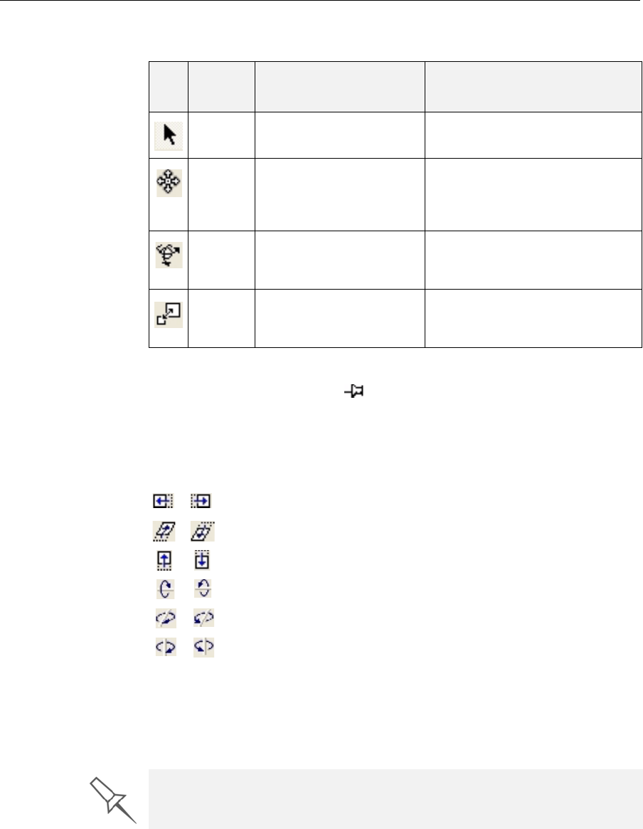
Icon Menu
Option Purpose What to do
(none) Forselectinganobject. Clicktheobjectonthebuildtray.
Object>
Translate Forselectingandmoving
anobjectwiththemouse. Clicktheobjecttoselectit.
Dragtheobjecttoanewlocation
whileholdingdownthemouse
button.
Object>
Rotate Forselectingandrotating
anobjectontheZ‐axis. Clicktheobjecttoselectit.
Holddowntheleftmousebutton
andmovethemouseleft/right.
Object>
Scale Forselectingand
changingthesizean
object.
Clicktheobjecttoselectit.
Holddowntheleftmousebutton
andmovethemouseleft/right.
Clicktomovetheobject20mmalongtheX‐axis.
Clicktomovetheobject20mmalongtheY‐axis.
Clicktomovetheobject30degreesontheZ‐axis.
Clicktorotatetheobject30degreesontheX‐axis.
Clicktorotatetheobject30degreesontheY‐axis.
Clicktorotatetheobject30degreesontheZ‐axis.
The object-properties dialog box is displayed by default (see figure 5-5 on
page 5-4) and whenever the screen layout is changed or refreshed (see
“Arranging the Objet Studio Screen” on page 5-6).
DRAFT 4 - July 11, 2010
DOC-24000 Rev. A 5–13
Alaris30 User Guide
Figure 5-16: Object properties dialog box, Transform tab
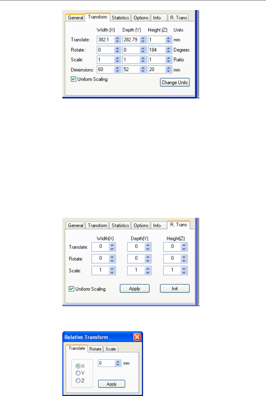
Youcanmakeprecisechangestoanobjectonthebuildtraybyselectingthe
object(eitheronthetrayorinthetrayhierarchypane),changingitsvalues
inthedialogbox,andclickingChange Units.
Note: You can only change the height of the objects on the build tray if this
is allowed by the Objet Studio settings (see “Object Position on the
Z-Axis” on page 5-11.)
ThepropertiesdisplayedintheTransformtaboftheobjectpropertiesdialog
boxareabsolutevalues,representingtheactualpositionoftheobjectonthe
buildtray.Anotherwayofrepositioningobjectsonthetrayusingprecise
valuesisbyapplyingchangestoobjectpropertiesrelativetothecurrent
position.TherearetwoRelativeTransformdialogboxesavailable:
•TheR.Transtaboftheobjectpropertiesdialogbox.
Figure 5-17: Object properties dialog box, R. Trans tab
•TheRelativeTransformdialogbox,accessiblefromtheObjectmenu.
Figure 5-18: Relative Transform dialog box
DRAFT 4 - July 11, 2010
Using Objet Studio
5–14
DOC-24000 Rev. A
Valid Object
Placement Toensurethatmodelsdonotoverlapwhenyoupositionthemonthebuild
tray,youcanselecttheDynamicCheckingiconfromtheToolstoolbar.
Whenselected,ObjetStudioonlyallowsthepositioningofobjectsifthey
donotinterferewithotherobjectsonthetray.Notethatthespaceoccupied
byanobjectincludesthe“boundingbox”surroundingit(seefigure 5‐24on
page 5‐19).
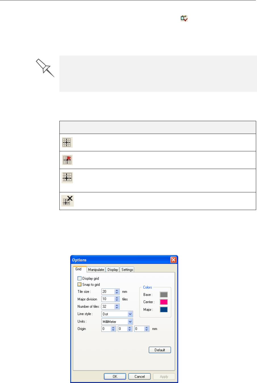
Using a Grid to
Position
Objects
Displayingagridontheimageofthebuildtraycanbeusefulwhen
positioningobjects.Youcanmakeuseofthisfeaturebyclickingthegrid
toolbariconsorbyselectingmenuoptions.
Youcanreviewandconfiguregridsettings—andapplythem—fromthe
Optionsdialogbox.
To use the Options dialog box:
1. FromtheToolsmenu,selectOptions,anddisplaytheGridtab.
Figure 5-19:Options dialog box, Grid tab, showing the default settings
EvenifyoudonotuseDynamicCheckingwhenplacingobjectsonthebuild
tray,ObjetStudioautomaticallychecksifthereisaproblemwiththe
positioningofobjectsonthetraybeforesendingittotheprinter.Youcan
alsomanuallycheckforproblemsafterpositioningobjects(see“Tray
Validation”onpage 23).
Icon Menu Option Result
Tools>Grid Displaysagridoverallbuildtrayviews.
Tools>Snaptogrid Whenmovingtheobject,italignswiththe
nearestgridline.
Enablesyoutochangethegridorigin
(X‐andY‐axismeetingpoint)byclicking
onthebuildtray.
Cancelsthechangesmadetothegrid
originandrestoresthedefaultgrid.
DRAFT 4 - July 11, 2010
DOC-24000 Rev. A 5–15
Alaris30 User Guide
Thedialogboxdisplaysthecurrentgridsettings.
2. Asrequired,makechangestothesettings,andselectorclearthecheck
boxes.
3. ClickApplyorOK.
Changing an
Object’s
Orientation
Thereareseveralmethodsforchangingtheorientationofobjectsonthe
buildtray.
To rotate an object:
¾SelecttheobjectandusetheRotateiconorObjectmenuoptions(see
“RepositioningObjects”onpage 5‐12).
To select an object’s plane and re-align it with one of six basic directions:
•FromthePlaneAlignmenttoolbar:
1. ClicktheSelectPlaneicon.
2. Clickaplaneonanobjectdisplayedonthebuildtray.
3. Clicktheappropriatealignicon—
•FromtheToolsmenu:
1. SelectPlane Alignment > Select Plane.
2. Clickaplaneonanobjectdisplayedonthebuildtray.
3. SelectPlane Alignment > Align Bottom/Top/Front/Back/Left/Right(as
appropriate).
Note: When you are finished re-aligning the plane of objects on the build
tray, release the Select Plane icon or clear “Select Plane” from the
Tools > Plane Alignment menu.
To flip an object 180 degrees on any axis:
1. Selecttheobject.
2. FromtheObjectmenu,selectFlip > Flip X / Flip Y / Flip Z.
To make precise changes to the object’s orientation on any axis:
1. Selecttheobject.
2. DisplaytheTransformtabortheR.Trans.taboftheobjectproperties
dialogbox(seefigure 5‐16onpage 5‐13andfigure 5‐17onpage 5‐13).
or—
FromtheObjectmenu,selectRelative Transform (seefigure 5‐18on
page 5‐13).
3. ChangetheRotatevaluesforthedesiredaxis.
AlignBottom
AlignTop
AlignFront
AlignBack
AlignLeft
AlignRight
DRAFT 4 - July 11, 2010
Using Objet Studio
5–16
DOC-24000 Rev. A
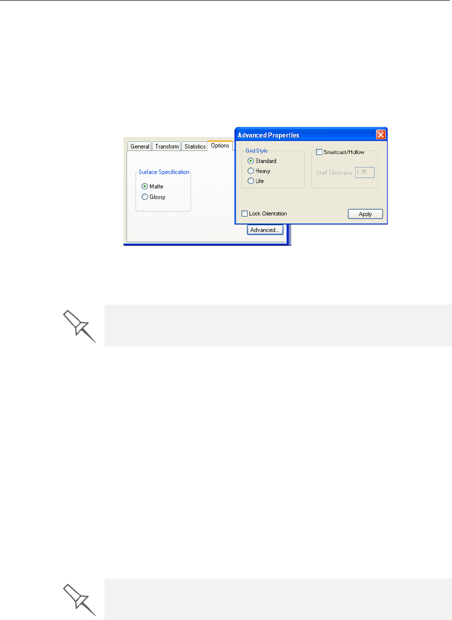
Freezing an
Object’s
Orientation
Ifyoumanipulateanobjectonthebuildtray,youcanfreezeitsorientation
sothatitdoesnotchangewhenyouperformAutomaticPlacement(see
“A u t o m a t i c Positioning”onpage 5‐8).
To freeze an object’s orientation:
1. Selectamodelonthebuildtray.
2. IntheOptionstaboftheobjectpropertiesdialogbox,clickAdvanced.
TheAdvancedPropertiesdialogboxopens.
Figure 5-20:Advanced Properties dialog box
3. SelecttheLockOrientationcheckbox.
4. ClosetheAdvancedPropertiesdialogbox.
Surface Finish Modelscanbeproducedwithamatteorglossyfinish.Tocreateamatte
finish,theprintersurroundsmodelswithathinlayerofsupportmaterial.
To choose the finish type for a model:
1. Selectthemodel.
2. IntheOptionstaboftheobjectpropertiesdialogbox,selectMatteor
Glossy.
or—
1. Right‐clickthemodelonthebuildtray.
Atthebottomofthecontextmenu,thecurrentfinishtypeisnotenabled
(thatis,youcannotselectit).
2. Tochangethefinishtype,selecttheother(enabled)option.
Youcandistinguishbetweenthefinishofobjectsonthebuildtraybytheir
color.Whentheyarenotselected,objectsaredisplayedinadifferentshade
ofgreenforeachfinish.
You can set Lock Orientation as a default property for all models placed on
the build tray. See “Default Object Properties” on page 17.
You can set the surface finish as a default property for all models placed on
the build tray. See “Default Object Properties” on page 17.
DRAFT 4 - July 11, 2010
DOC-24000 Rev. A 5–17
Alaris30 User Guide
Default Object
Properties Youcansetseveraldefaultpropertiesforobjectsplacedonthebuildtray:
•lockingofobjectorientationonthetray
Foranexplanationofthisfeature,seeFreezinganObject’sOrientation
onpage 5‐16.
•surfacefinishforprintedmodels
Foranexplanationofthisfeature,seeSurfaceFinishonpage 5‐16.
•supportstrengthusedduringprinting
Foranexplanationofthisfeature,seeChoosingtheSupportStrengthon
page 5‐26.
•“smartcast”printing
Foranexplanationofthisfeature,see“Smartcast”—FillingModelswith
SupportMaterialonpage 5‐27.
To set any of these default properties:
¾FromtheFilemenu,selectDefault Properties.
Figure 5-21: Setting default properties for objects
DRAFT 4 - July 11, 2010
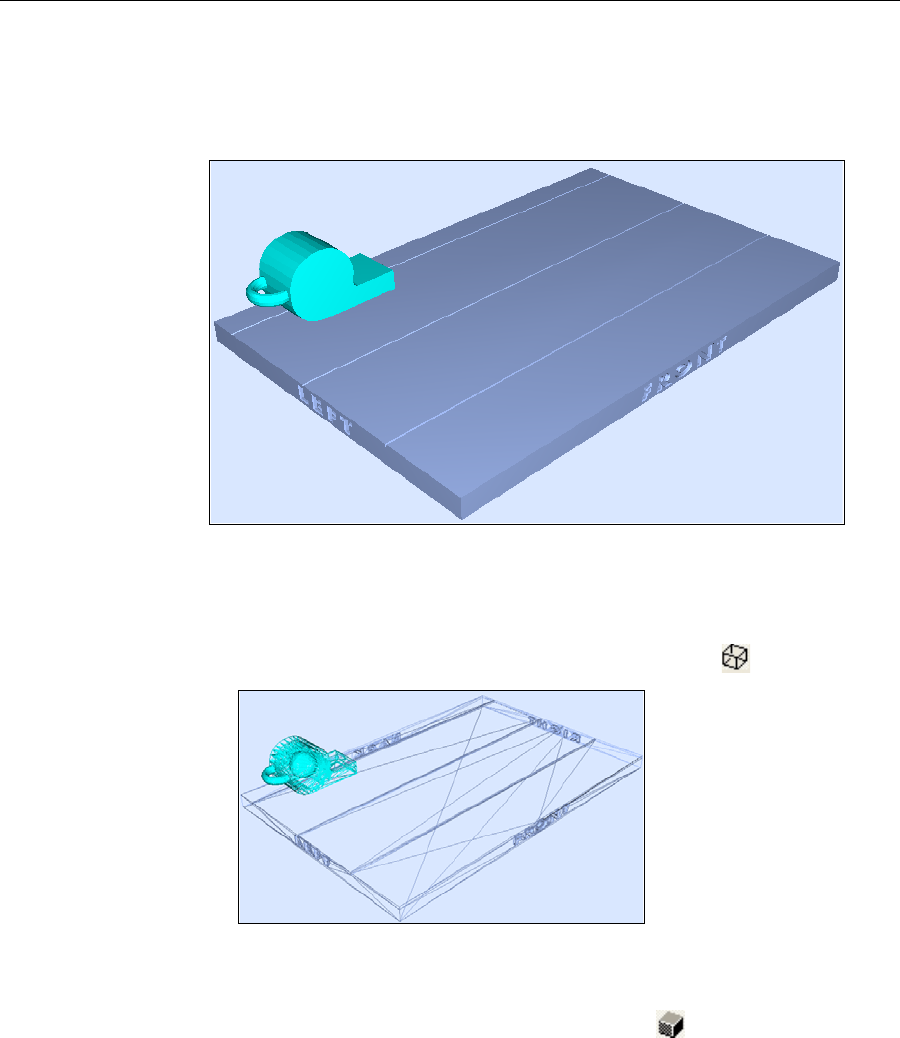
Using Objet Studio
5–18
DOC-24000 Rev. A
Display Options
FromtheViewmenu,youcanchangethewayobjectsaredisplayedonthe
screen.Thedefaultmethodfordisplayingmodelsonthebuildtrayisas
solid(“shaded”)objects.
Figure 5-22: Tray and model displayed in shaded view
Theotherdisplayoptionsarewireframeandpoints.
To display the build tray in wire frame view:
¾SelectView> WireFrameorclicktheWireFrameicon.
Figure 5-23: Tray and model displayed in Wire frame view
To revert to the shaded view:
¾SelectView > ShadedorclicktheShadedicon.
To display objects as boxes, showing their maximum dimensions
instead of the model geometry:
¾SelectView > Display Bounding Box.
DRAFT 4 - July 11, 2010
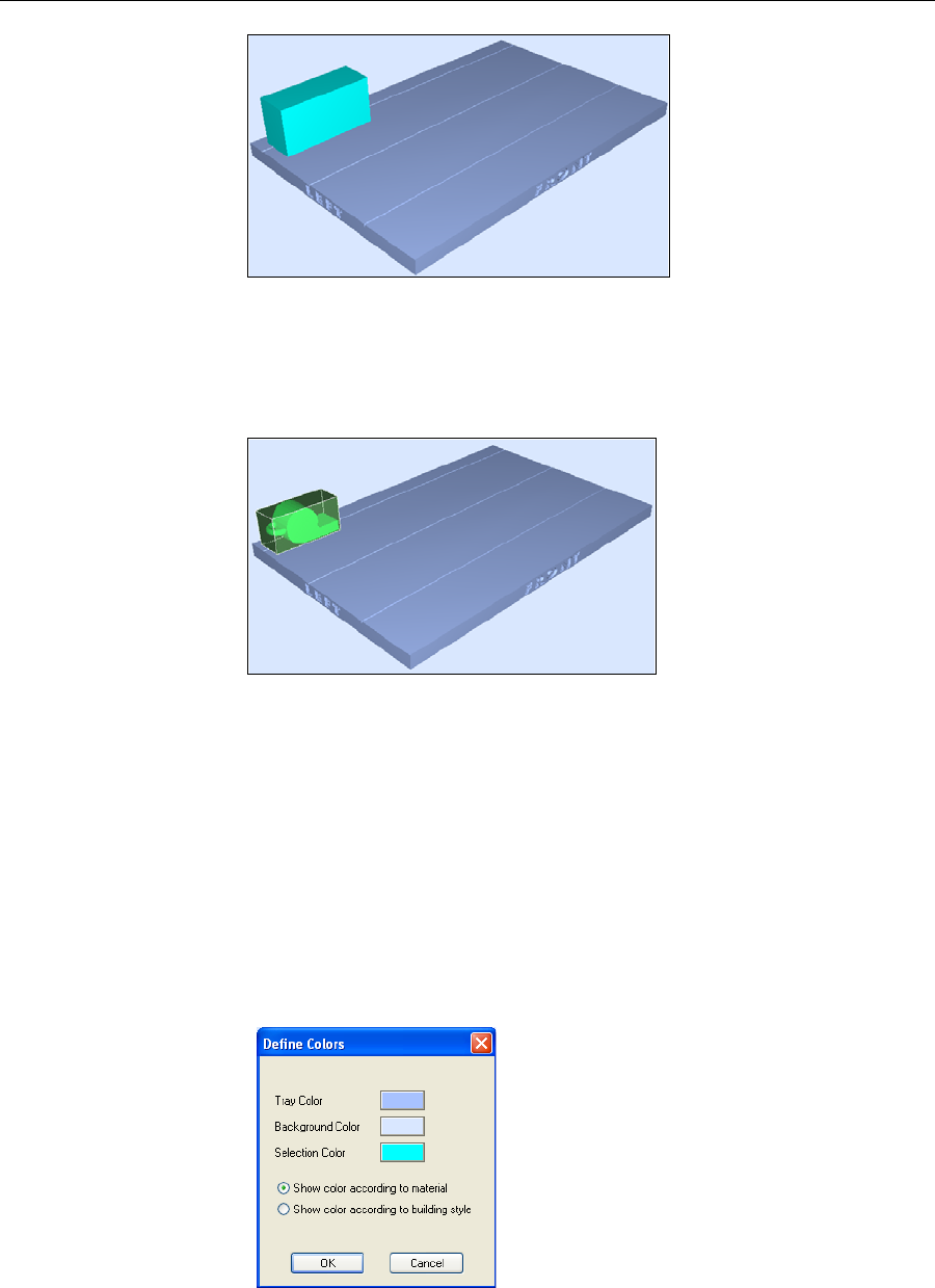
DOC-24000 Rev. A 5–19
Alaris30 User Guide
Figure 5-24: Model displayed with bounding box
To display the area around objects needed for support material (to
produce a matte finish):
¾SelectView > Display Thickening Box.
Figure 5-25: Model displayed with thickening box
Display Colors YoucancustomizesomeofthecolorsusedfordisplayingObjetStudio
screensandfordisplayingobjectsonthebuildtray.
To change the colors displayed in Objet Studio screens:
1. FromtheToolsmenu,selectDefine Colors.
2. IntheDefineColorsdialogbox,clickthecolorpatchyouwantto
change:
•TrayColor—tochangethecolorofthebuildtray
•BackgroundColor—tochangethebackgroundcolor
•SelectionColor—tochangethecolorofobjectsthatareselected
Figure 5-26:Define Colors dialog box
3. IntheColorsdialogbox,selectacolor,orclickDefine Custom Colorsto
createyourowncolorandshadefordisplayingthisitem.
4. ClickOK.
DRAFT 4 - July 11, 2010
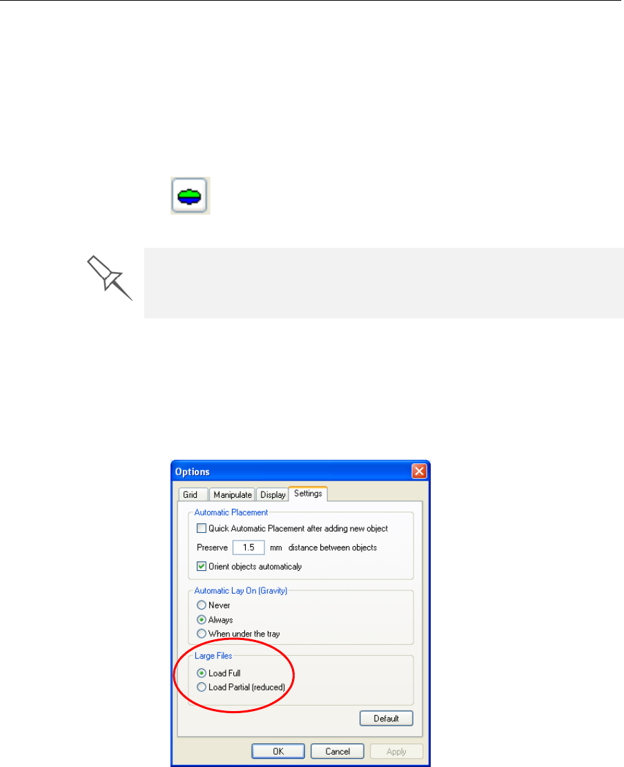
Using Objet Studio
5–20
DOC-24000 Rev. A
To set the color indication of objects displayed on the build tray:
1. IntheDefineColorsdialogbox,selectoneoftheoptions.
•Showcoloraccordingtomaterial.
•Showcoloraccordingtobuildingstyle.
2. ClickOK.
Note: This selection has the same effect as toggling the object-color-
display switch.
Figure 5-27:Object-color-display switch
Displaying
Large Files Verylargestlfilescanbeslowtodisplayandmaybedifficulttomanipulate
easilyonthebuildtray.Ifthisisthecase,youcandisplayjustanimageof
theobjectonthebuildtraywithoutloadingtheentirefile.Thestlfileitself
isnotchanged,andthecompletefileissenttotheprinter.
To display an image of stl files when you place objects on the build tray:
1. FromtheToolsmenu,selectOptions,anddisplaytheSettingstab.
Figure 5-28:Options dialog box, Settings tab
2. IntheLargeFilessection,selectLoad Partial.(Load Fullisthedefault
setting.)
Before sending a build tray to the printer, or when you perform tray
validation, Objet Studio checks if there is a problem with the stl files or the
positioning of objects on the tray. If so, the affected objects are displayed
with special colors (see “Tray Validation” on page 5-23).
DRAFT 4 - July 11, 2010
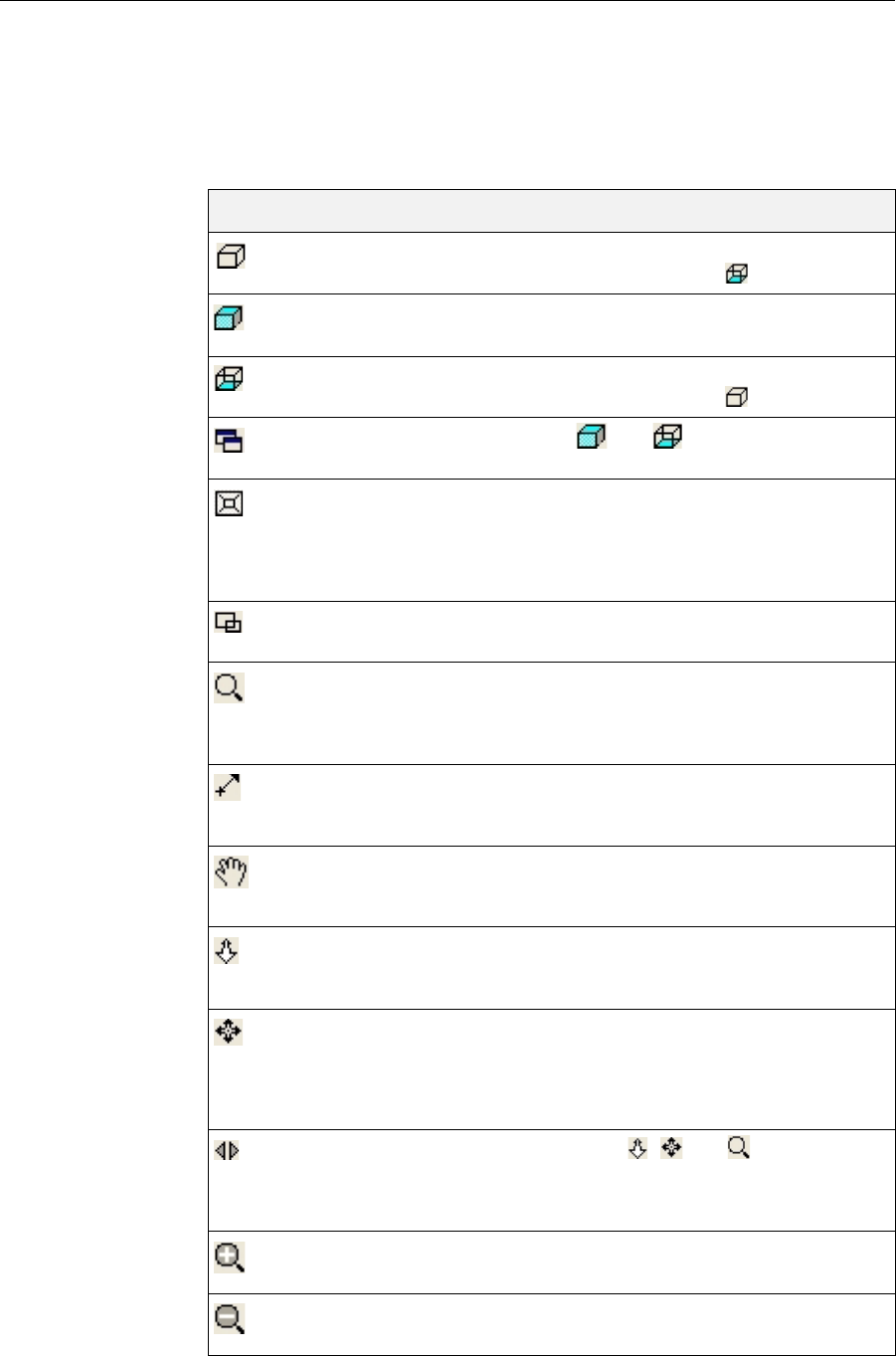
DOC-24000 Rev. A 5–21
Alaris30 User Guide
Tray Viewing
Options TheObjetStudiotoolbarscontainseveraliconsforchangingthe
appearanceofthedisplayscreen,enablingyoutoviewthetrayandobjects
indifferentmagnificationsandfromvariousperspectives.
Note: You must display the relevant toolbar(s) to access many of the icons
described below (see “Toolbars” on page 5-2).
Icon Tool Tip Name Purpose
ZoomFull Revertstonormalviewafterusingvarious
zoomoptions.(Thesameas.)
ZoomObjectFillstheviewingpanewiththeselected
object(s).
ZoomWorkArea Revertstonormalviewafterusingvarious
zoomoptions.(Thesameas.)
AllWindows Ifenabled,andaffectallviewing
panes.
Perspective/Parallel Whenselected,thetrayisdisplayedwithdepth
perspective—closerobjectsappearbigger.
Whennotselected,thetrayisdisplayedintwo
dimensions—identicalobjectsappearthesame
size,regardlessoftheirpositiononthescreen.
ZoomByRectangle Fillstheactiveviewingpanewithanareaofthe
buildtrayafteryouselectitwiththemouse.
ZoomDynamic Continuouslyzoomsin/outofthepointat
whichyouclickandholddowntheleftmouse
button,whenyoumovethecursorupand
down.
PanByLine Movesthebuildtrayintheviewingpane
accordingtothelineyouextendonthescreen
withtheleftmousebutton.
PanDynamic Movesthebuildtrayintheviewingpaneas
youmovethecursoronthescreenwhile
holdingdowntheleftmousebutton.
WalkDynamic Zoomsandmovesthebuildtrayasyouhold
downtheleftmousebuttonandmovethe
cursoronthescreen.
StudyDynamic Enablesyoutoinspectthebuildtrayfrom
everyangleandperspective.Asyouhold
downtheleftmousebuttonandmovethe
cursoronthescreen,theviewofthebuildtray
changes.
SpinMode Whenusedwith,and,themovement
ofthebuildtraycontinuesafteryoureleasethe
mousebutton.Tostopthemovement,clickin
theactiveviewpaneorclickoneoftheseicons.
ZoomIn Eachmouseclickzoomsonesteptothecenter
oftheactiveviewingpane.
ZoomOut Eachmouseclickzooms‐outonestepfromthe
centeroftheactiveviewingpane.
DRAFT 4 - July 11, 2010
Using Objet Studio
5–22
DOC-24000 Rev. A
PanLeft Eachmouseclickmovesthebuildtraytothe
leftintheviewingpanebyonestep.
PanRight Eachmouseclickmovesthebuildtraytothe
rightintheactiveviewingpanebyonestep.
PanUp Eachmouseclickmovesthebuildtrayupin
theactiveviewingpanebyonestep.
PanDown Eachmouseclickmovesthebuildtraydownin
theactiveviewingpanebyonestep.
AdvanceForward Thesameas.Eachmouseclickzoomsinto
thetraydisplayedintheactiveviewingpane.
AdvanceBackward Thesameas.Eachmouseclickzoomsout
ofthetraydisplayedintheactiveviewing
pane.
RotateLeft Eachmouseclickrotatesthebuildtraytothe
leftintheactiveviewingpanebyonestep.
RotateRight Eachmouseclickrotatesthebuildtraytothe
rightintheactiveviewingpanebyonestep.
RotateUp Eachmouseclickrotatesthebuildtrayupin
theactiveviewingpanebyonestep.
RotateDown Eachmouseclickrotatesthebuildtraydownin
theactiveviewingpanebyonestep.
Camera Displaysavirtualcameraanditsviewingangle
ofthetray.
Icon Tool Tip Name Purpose
DRAFT 4 - July 11, 2010
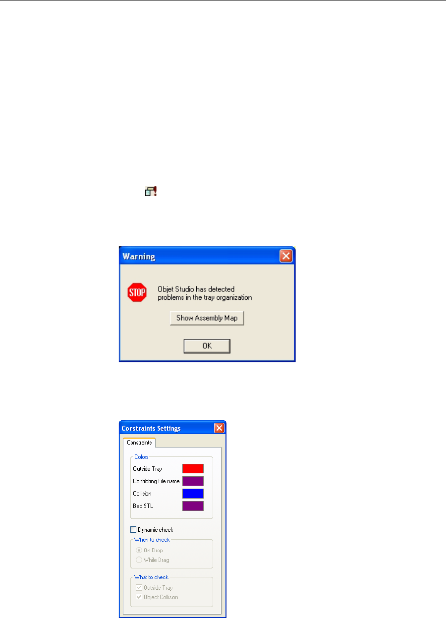
DOC-24000 Rev. A 5–23
Alaris30 User Guide
Handling Completed Trays
Afteryouhaveproperlyplacedallobjectsonthebuildtray,yousavethe
trayasanobjtffile,whichissenttothe3‐Dprinterforproduction.But
beforesavingthetray,youcancheckthattherewouldbenoproblem
producingit.Youcanalsocalculatehowmuchmaterialwouldbe
consumedduringproductionandhowmuchtimethiswouldtake.
Tray Validation BeforesendingajobtotheAlarisprinterforproduction,youshouldcheck
thatthetrayis“valid”andcanbeprinted.
To validate that the tray can be printed:
¾FromtheToolsmenu,selectTray Validation.
or—
¾Click.
Ifthetrayisnotvalid,thecoloroftheproblematicmodelsonthetray
changesaccordingtoapre‐setcolorcode.Ifawarningmessageappears,
clickOKtocloseit.
Figure 5-29: Tray validation warning
To view the color code for objects displayed:
¾FromtheToolsmenu,selectConstraints Settings.
Figure 5-30: Constraints Settings dialog box, showing object color codes
DRAFT 4 - July 11, 2010
Using Objet Studio
5–24
DOC-24000 Rev. A
Production
Estimates ObjetStudioenablesyoutocalculatethetimeandmaterialresources
neededforproducingtraysbeforesendingthemtotheAlarisprinter.The
timeittakesObjetStudiotomakethiscalculationdependsonthenumber
ofobjectsonthetrayandtheircomplexity.Calculatingtheproduction
estimateforafulltraycouldtakeupto15minutes,dependingonyour
computer’sspecifications.Theresultsdisplayedareaccuratewithin10
percentoftheactualresourcesneeded.
To calculate the time and materials needed for producing the current
tray:
¾FromtheToolsmenu,selectEstimate Consumptions.
or—
¾Click.
WhenObjetStudiofinishescalculatingtheproductionresources,the
resultsaredisplayedatthebottomofthescreen.
Figure 5-31: Production resource calculation
Saving the
Tray File Traysaresavedasobjtffiles.Youcansaveatraybeforeitisreadyfor
production,andopenitatanothertimetocontinuepreparingit.Whenyou
sendthetraytotheAlarisprinter,itisfirstsaved.Ifthetraywaspreviously
saved,itsobjtffileisoverwrittenatthistime.
To save the tray file:
¾FromtheFilemenu,selectSave TrayorSave Tray As.
or—
¾Click.
Printing the
Tray File Whenatrayisreadytobeprinted,itissenttoJobManager,whereitis
placedintheprintqueue.Whenthejobreachestheheadofthequeue,Job
Managerpre‐processesthetrayfiletocreateslices,andfeedsthemtothe
3‐Dprinter.
To send the tray to the print queue:
¾FromtheFilemenu,selectBuild Tray.
or—
¾Click.
Ifthebuild‐trayfilehasnotbeensaved,theSaveAsdialogboxopensfor
youtosaveitnow.
ObjetStudiochecksifthereisaproblemwiththepositioningofobjects
onthetray.Ifso,theaffectedobjectsaredisplayedwithspecialcolors
(seefigure5‐30onpage 5‐23),andthefollowingwarningmessage
appears.
DRAFT 4 - July 11, 2010
DOC-24000 Rev. A 5–25
Alaris30 User Guide
Figure 5-32: Tray validation warning
TocanceltheBuildcommandsoyoucancorrecttheproblem,click
No.
Toprintthemodelsastheyarepositionedonthetray,clickYes.
Figure 5-33: Constraints Settings dialog box, with color codes for problematic
model positioning
The tray file is sent to Job Manager. Objet Studio closes and Job Manager
opens, so you can monitor the progress of your trays—before, during, and
after printing.
To return to Objet Studio from Job Manager, click New Job .
DRAFT 4 - July 11, 2010
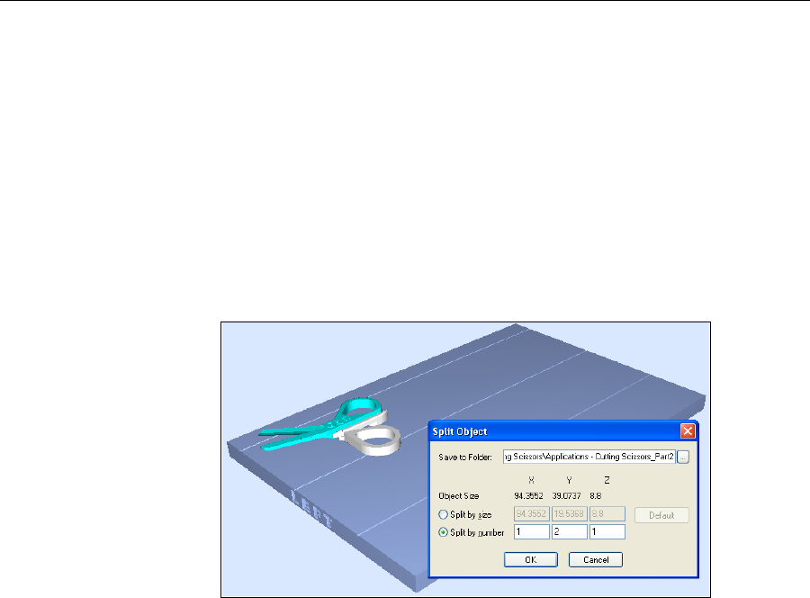
Using Objet Studio
5–26
DOC-24000 Rev. A
Additional Objet Studio Features
Dividing
Objects YoucanusetheSplitObjectfeaturetoproduceobjectslargerthanthebuild
traybydividingthemodelintoseparateparts.Withthisfeature,you
produceonlyaspecificsectionofamodel.
To split an object:
1. Selecttheobject.
2. FromtheObjectmenu,selectSplit.
3. IntheSplitObjectdialogbox,enterthevaluestodeterminehowObjet
Studiowilldividetheobject.Youcandivideanobjectalonganyofits
axes,byenteringeitherexactmeasurementsorthenumberofparts.
Figure 5-34:Split Object dialog box
4. InSavetoFolder,enterthefoldername.
5. ClickOK.
Thecompositepartsaresavedasnewstlfileswith“Part1,”“Part2,”
etc.,addedtotheoriginalfilename.
Note: Before printing the newly created stl files, it is recommended that you
check them for defects in an STL-repair application, such as Magics,
by Materialise.
Choosing the
Support
Strength
Whenproducingmodels,supportmaterialfillssomehollowandempty
sections(see“ModelOrientation”onpage 5‐10).ObjetStudioallowsyouto
adjustthestrengthofthestructureformedwiththesupportmaterial.This
adjustmentisusefulwhenproducingeitherlarge/massivemodelsorsmall/
delicatemodels.Formostpurposes,thedefaultsettingprovidesadequate
supportstrength.
To change the strength of the support structure used when printing a
model:
1. Selectamodelonthebuildtray.
2. IntheOptionstaboftheobjectpropertiesdialogbox,clickAdvanced.
DRAFT 4 - July 11, 2010
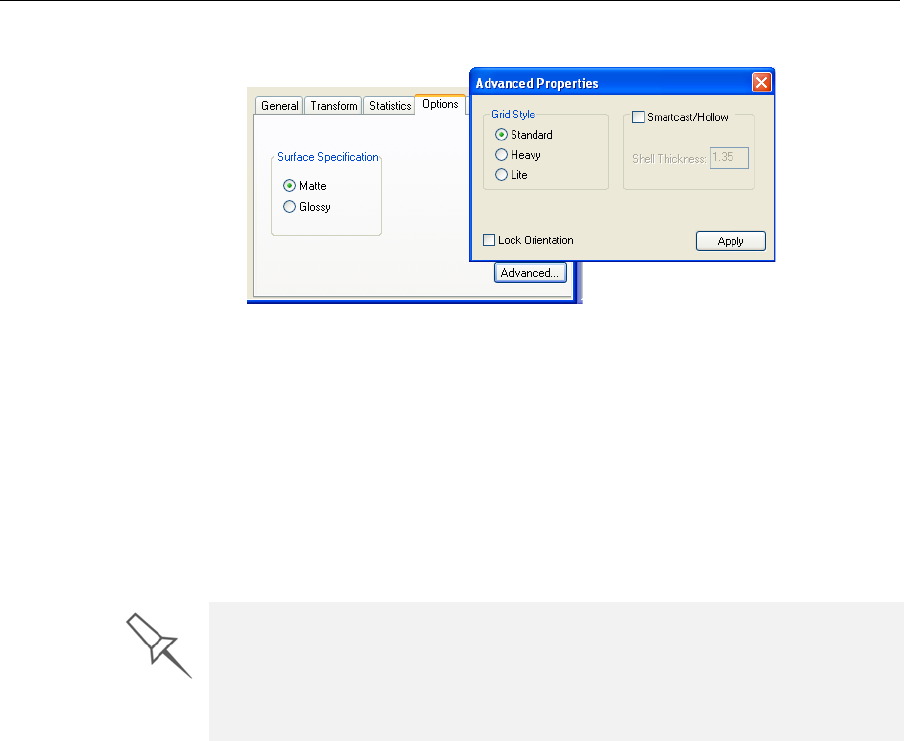
DOC-24000 Rev. A 5–27
Alaris30 User Guide
TheAdvancedPropertiesdialogboxopens.
Figure 5-35:Advanced Properties dialog box—Grid Style selection
3. IntheGridStylesection,choosethesupportstrengthsuitableforthe
selectedmodel:
•Heavy—forlargemodelsneedingmuchsupport.
•Lite—fordelicatemodelsneedinglittlesupport.
•Default—formodelsneedingaveragesupport(mostmodels).
Note: You can select a different support strength for each model on the
build tray.
4. ClickApply.
“Smartcast”—
Filling Models
with Support
Material
Manyobjectsplacedonthebuildtrayfromstlfilesare“solid.”Thismeans
that,whenprinted,themodelwillbecompletelyfilledwithmodel
material.Often,especiallywithlargeobjects,thisisunnecessary.Instead,
themodelcanbefilledwithsupportmaterial,whichislesscostly.Itisalso
advisabletofillmodelswithsupportmaterialwhenpreparingthemfor
investmentcasting,sincethismaterialburnsoffmorequicklyduringthe
processofmakingthecast.
ObjetStudioenablesyoutoprintobjectsonthebuildtraywithanouter
shellofmodelmaterialandacenterfilledwithsupportmaterial.This
featureofObjetStudioiscalled“Smartcast/Hollow.”Youcansetthe
thicknessoftheshell—between0.015and3.825millimeters.
To use the Smartcast/Hollow feature:
1. Selectamodelonthebuildtray.
2. IntheOptionstaboftheobjectpropertiesdialogbox,clickAdvanced.
TheAdvancedPropertiesdialogboxopens(seefigure 5‐35).
3. SelecttheSmartcast/Hollowcheckbox.
4. Settheshellthickness,inmillimeters.
5. ClickApply.
Note: There is no change in the display of objects in Objet Studio when the
Smartcast/Hollow feature is used.
The Lock Orientation and Smartcast/Hollow options are not connected to
the Grid Style selection. Lock Orientation is described in “Freezing an
Object’s Orientation” on page 5-16. Smartcast/Hollow is described below.
You can set the support strength as a default property for all models placed
on the build tray. See “Default Object Properties” on page 17.
DRAFT 4 - July 11, 2010
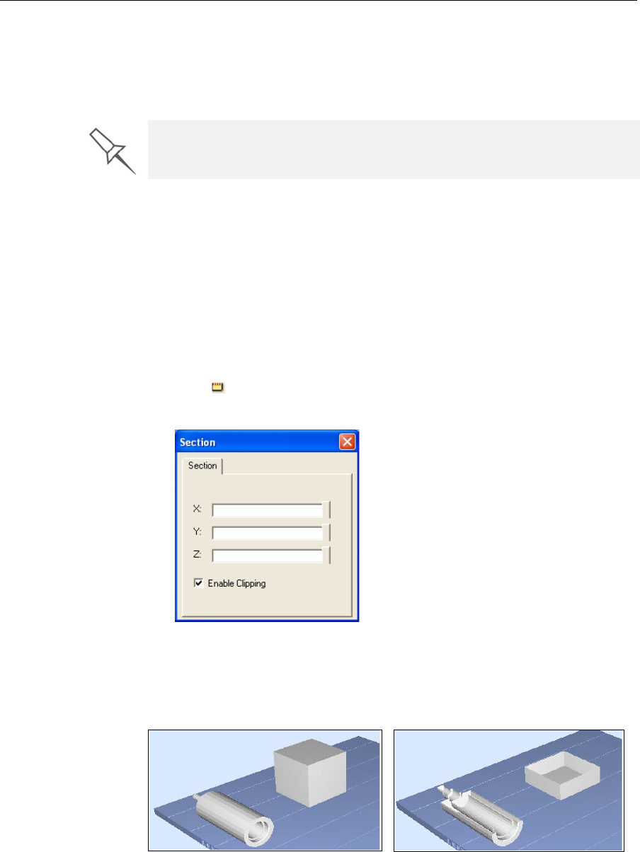
Using Objet Studio
5–28
DOC-24000 Rev. A
To inspect, change or cancel the Smartcast/Hollow setting:
1. Selectamodelonthebuildtray.
2. AccesstheAdvancedPropertiesdialogbox,asabove.
3. IfyouchangeorcanceltheSmartcast/Hollowsetting,clickApply.
Displaying the
Cross Section
of Objects
TheSectionfeatureenablesyoutoviewtheinteriorofanobjectby“slicing”
itonanyaxis.Youcanthenmanipulatetheobjecttoinspecttheinterior
fromdifferentangles.Thismaybeimportantfordecidingonthetypeof
supportnecessarywhenproducingthemodel(see“ChoosingtheSupport
Strength”onpage 5‐26).Displayinganobject’scrosssectiononlyaffects
howthetrayisdisplayedonthescreen;itdoesnotchangetheobjectitself.
To display a cross section of the tray:
1. FromtheToolsmenu,selectSection.
or—
Clickonthetoolbar.
TheSectiondialogboxopens.
Figure 5-36:Section dialog box
2. SelecttheEnableClickingcheckbox.
3. UsetheslidercontrolsfortheX‐,Y‐,andZ‐axestocutthetraysothat
youseethecrosssectionyouwant.
You can set Smartcast/Hollow as a default property for all models placed on
the build tray. See “Default Object Properties” on page 17.
Figure 5-37: Whole view Figure 5-38: Cross-section view, after
using the Z-slider
DRAFT 4 - July 11, 2010
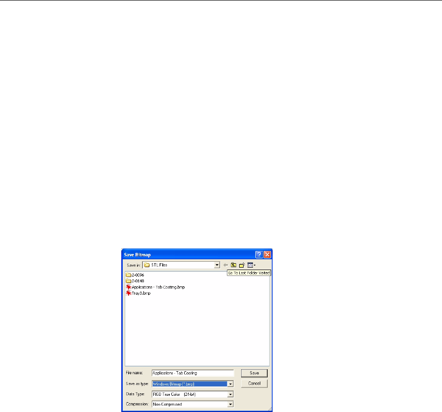
DOC-24000 Rev. A 5–29
Alaris30 User Guide
Printing the
Screen Display
on Paper
Youcanprinttheviewdisplayedintheactivepaneonaregular(paper)
printer.Beforeprinting,youcanconfigurehowthetraywillbeprintedon
thepage,andyoucandisplayascreenpreviewoftheprintedpage.
To access the paper printing controls:
¾FromtheFilemenu,select—
Page Setup…
Page Preview…
Print
YoucanalsoprintapapercopyofthetraybyusingthestandardWindows
keyboardshortcutforprinting:Ctrl+P.
Saving the
Screen Display
as an
Image File
Youcansavetheimagedisplayedintheactiveviewingscreenasagraphic
file.
To save the screen display as an image:
1. FromtheFilemenu,selectSave Bitmap…
TheSaveBitmapdialogboxopens.
Figure 5-39:Save Bitmap dialog box
2. Atthetopofthedialogbox,selecttheappropriatefolder.
3. Atthebottomofthedialogbox,enterafilename.
4. OpentheSaveastypepull‐downmenu,andselectthefileformat.
5. ClickSave.
Exporting and
Importing
Objet Build
Trays
WhenyousavebuildtraysinObjetStudio,theyaresavedasobjtffiles.
ThesefilescontaininstructionstoObjetStudioandtoAlarisprintersfor
displayingandproducingthestlfilesusedonthetray.Toconveniently
saveallofthefilesthatcomprisethebuildtray,forstoringthejob,orfor
transferringittoanotherlocation,ObjetStudiocompressesthemintoone
objzffile.Tolaterusetheobjzffile,thefilemustfirstbeexpandedinObjet
Studioanditscomponentfilessaved.
To create an objzf file:
1. FromtheFilemenu,selectExport Packed Job…
TheSaveAsdialogboxopens.
2. Selecttheappropriatefolderandchangethefilename(ifnecessary).
3. ClickSave.
DRAFT 4 - July 11, 2010
Using Objet Studio
5–30
DOC-24000 Rev. A
To open an objzf file:
1. FromtheFilemenu,selectImport Packed Job…
2. IntheOpendialogbox,displaytheappropriatefolderandselectthe
file.
3. IntheBrowseforFolderdialogbox,displaythefolderinwhichyou
wantObjetStudiotoexpandthecompressedfile,andclickOK.
Theobjtffileandassociatedstlfilesareexpandedandplacedinthe
selectedfolder,andthetrayisdisplayedinObjetStudio.
Advanced-Mode Features
TheObjetStudiofeaturesdescribedinthissectionareonlyaccessibleifthe
applicationissettoAdvancedmode.
To see the current Objet Studio setting:
¾OpentheToolsmenu.
Figure 5-40: Tools menu, showing Advanced mode selected
IfAdvancedischecked,theadvancedfeaturesareenabled.
To change the Advanced setting:
1. ClickAdvancedintheToolsmenu.
Thefollowingmessageisdisplayed,remindingyouthatthechange
willonlytakeeffectthenexttimeyouopenObjetStudio—eventhough
thecheckmarkintheToolsmenuappears/disappearsafteryoumake
thechange.
Figure 5-41: Configuration-change message
2. Closeandre‐openObjetStudiotoaccesstheAdvancedmodefeatures.
DRAFT 4 - July 11, 2010
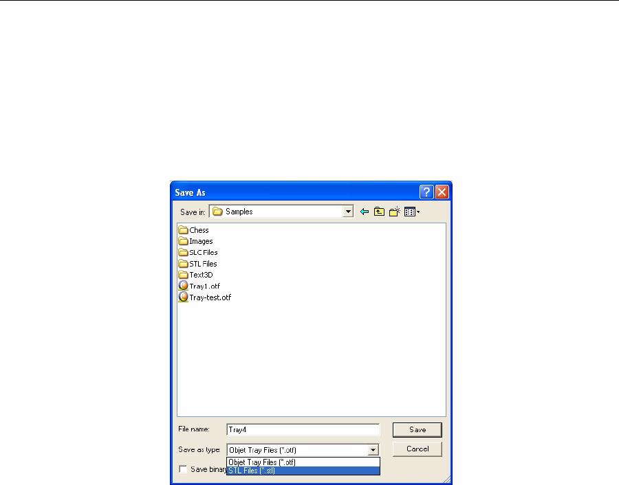
DOC-24000 Rev. A 5–31
Alaris30 User Guide
Save Tray As… Inadditiontosavingthetrayasanobjtffile,forproducingitwithanAlaris
3‐Dprinter,youcansaveagroupofobjectspositionedonthetrayasanstl
file.Youcanthenusethisfileasanyotherstlfile,bothinObjetStudioand
inotherapplications.Youcanalsodisplaythisandotherstlfilesas
“floating”objects,withoutthebuildtray.Thisisusefulforinspecting
objectsfromeveryangle.
To save the build tray as an stl object:
1. FromtheFilemenu,selectSave Tray As…
Figure 5-42:Save As dialog box
2. Atthetopofthedialogbox,selecttheappropriatefolder.
3. Atthebottomofthedialogbox,enterafilename.
4. OpentheSaveastypepull‐downmenu,andselectSTL Files (*.stl).
5. ClickSave.
To display stl files without the build tray:
1. FromtheFilemenu,selectOpen Tray.
2. IntheOpendialogbox,opentheFilesoftypepull‐downmenu,and
selectSTL Files (*.stl).
3. ClickOpen.
Athree‐dimensionalimageofthefileisdisplayed.Youcanusemanyof
theObjetStudiotoolstomanipulatetheimageonthescreen.
DRAFT 4 - July 11, 2010
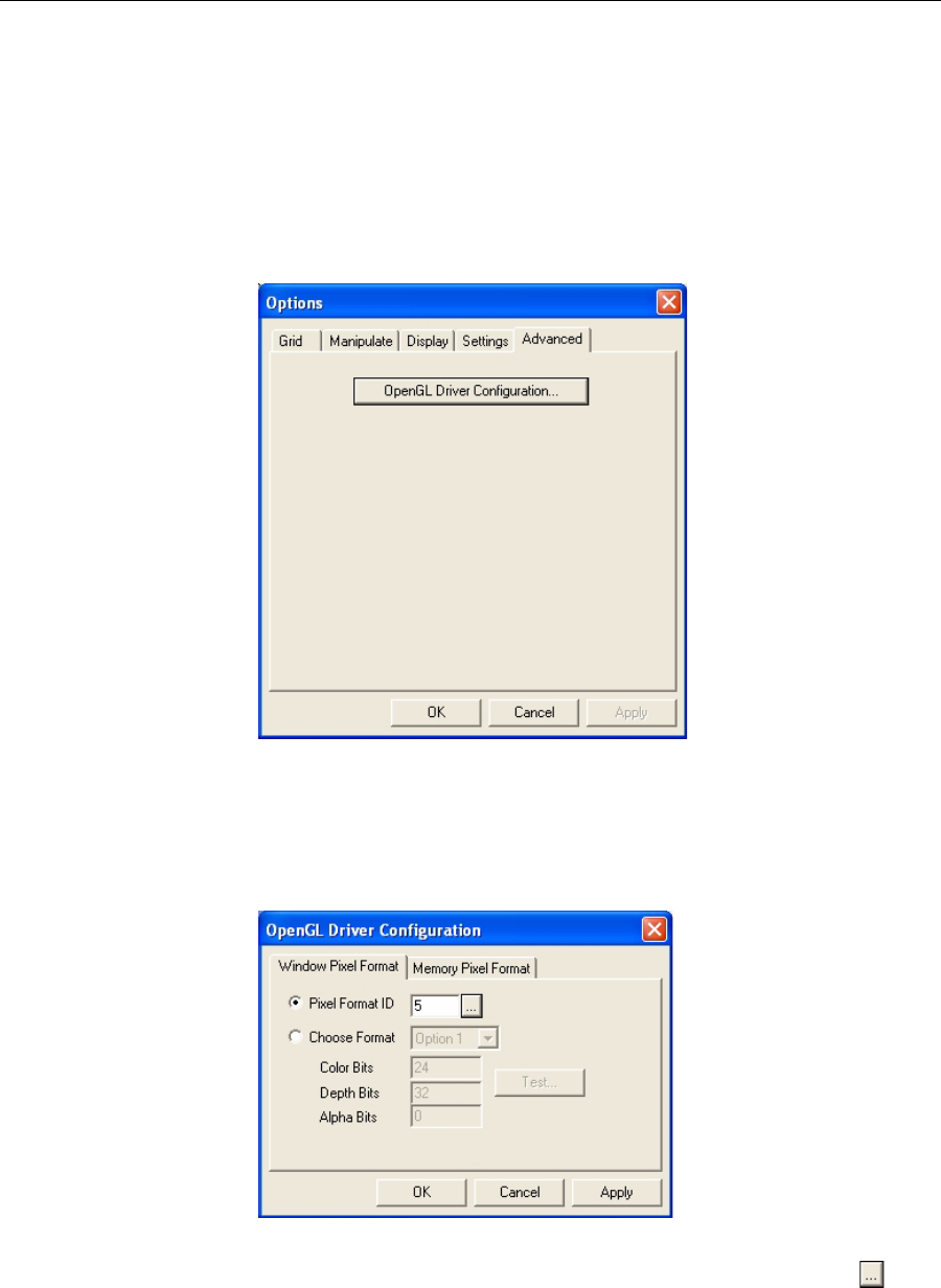
Using Objet Studio
5–32
DOC-24000 Rev. A
Configuring
the GL Driver TheOpenGLdriverdisplays3‐Dgraphicsonyourscreen.Thereis
normallynoreasontoadjustitssettings.Ifyoususpectaproblemwiththe
wayObjetStudiodisplaysobjects,youcanusetheOpenGLDriver
Configurationtooltocheckandconfigurethedriversettings.
To access the OpenGL Driver Configuration dialog box:
1. FromtheToolsmenu,selectOptions.
2. IntheOptionsdialogbox,displaytheAdvancedtabandclickOpenGL
Driver Configuration…
Figure 5-43:Accessing GL-driver configuration
Note: If the Advanced tab is not displayed, activate the Advanced option in
the Tools menu and re-open Objet Studio.
ThedialogboxthatopenscontainstabsthatdisplaythepixelformatID
(index)forthewindowandthememory.
Figure 5-44:OpenGL Driver Configuration dialog box
Youcandisplaythevaluesandmakechangestothembyclicking.
Alternately,youcanselectChoose Formatandchangethevaluesinthis
dialogbox.
DRAFT 4 - July 11, 2010
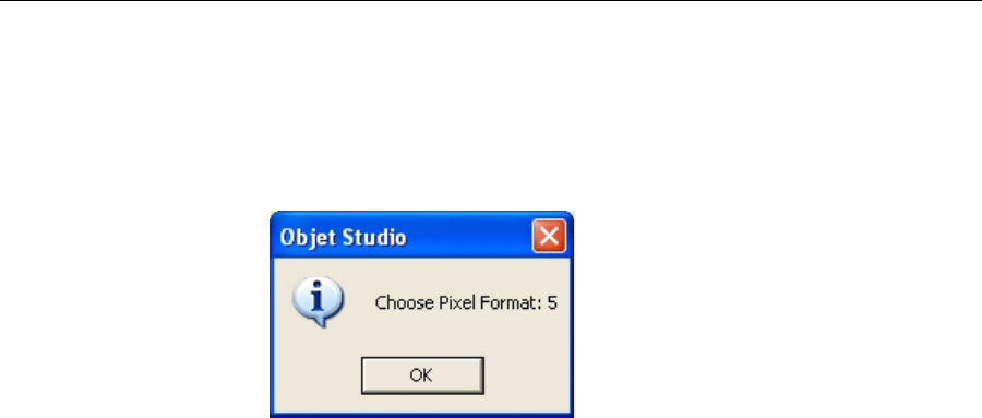
DOC-24000 Rev. A 5–33
Alaris30 User Guide
To perform a test of the driver configuration and enter the suggested
pixel format ID:
1. SelectChoose Format.
2. ClickTest.
ObjetStudioreturnstherecommendedpixelformatID.
Figure 5-45:Recommended pixel format ID
3. ClickOK.
4. IntheOpenGLDriverConfigurationdialogbox(figure 5‐44),select
Pixel Format IDandenterthisnumber.
5. ClickApply.
6. Displaytheotherpixelformattab,andrepeatthisprocedure.
DRAFT 4 - July 11, 2010

Using Objet Studio
5–34
DOC-24000 Rev. A
DRAFT 4 - July 11, 2010

DOC-24000 Rev. A 6–1
Using Job Manager
ClientJobManager.............................................................................. 2
JobManagerScreen .............................................................................. 3
JobManagerOperations ...................................................................... 4
ConfiguringUserAlerts....................................................................... 5
ServerJobManager............................................................................. 7
JobManagerScreen .............................................................................. 8
JobManagerOperations ...................................................................... 9
MakingchangestoaJob .................................................................... 10
UserAlerts............................................................................................ 11
SendingtheTraytothe3‐DprinterforProduction....................... 12
DRAFT 4 - July 11, 2010
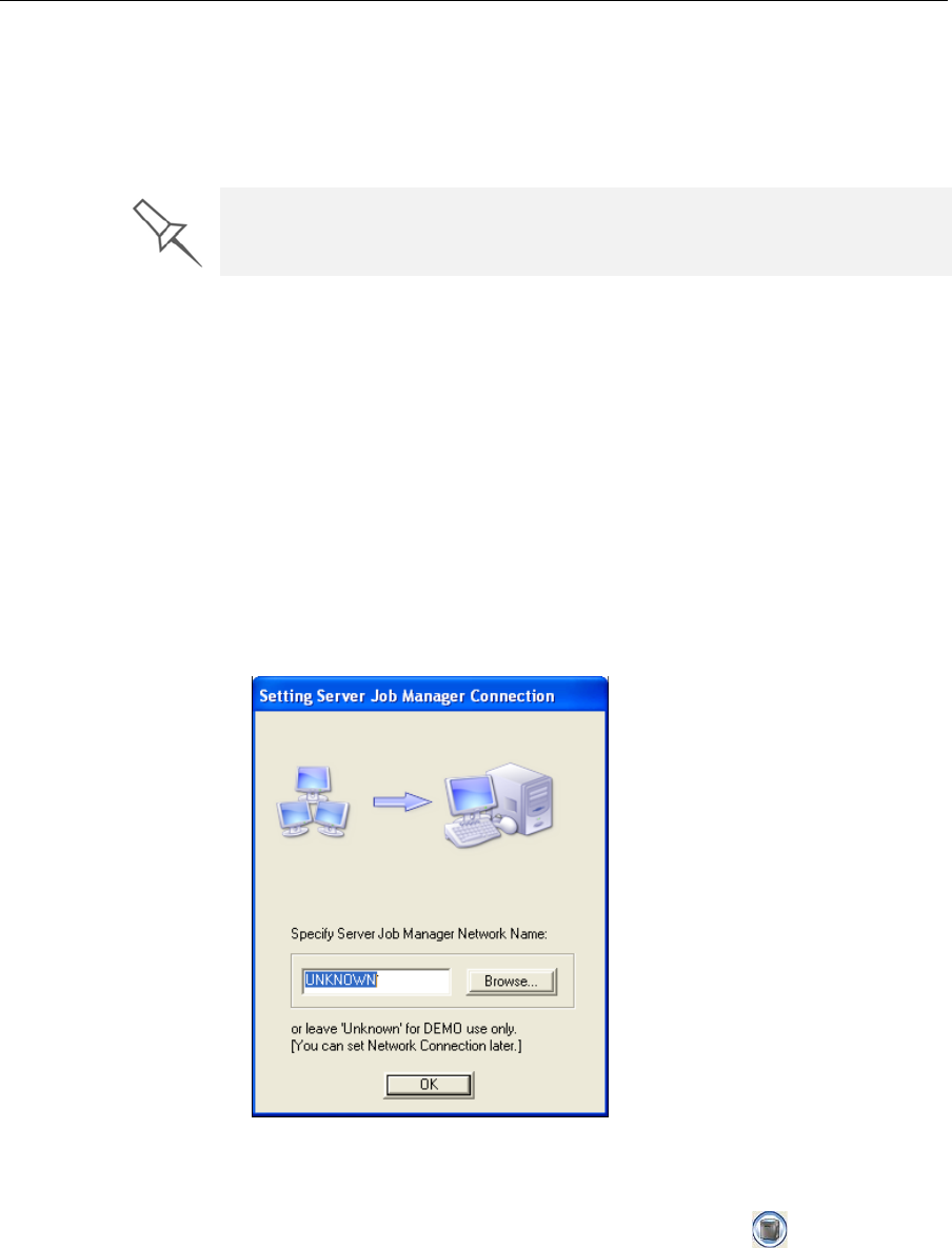
Using Job Manager
6–2
DOC-24000 Rev. A
TheJobManagerapplicationisdifferentforclientworkstationsandforthe
computerconnecteddirectlytothe3‐Dprinter.
•JobManagerinstalledonclientcomputersdisplaysthequeueand
statusonlyforjobssenttothe3‐Dprinterserverfromthatcomputer,
andallowstheusertoeditonlythesejobs.
•JobManagerinstalledonthecomputerdirectlyconnectedtoaspecific
3‐Dprinterdisplaysthequeueandstatusforalljobssenttothat3‐D
printerbyclientcomputersonthenetwork.Italsoallowseditingand
manipulationofalljobs,andenablesre‐sendingpreviously‐printed
jobstotheprinter.
Client Job Manager
WhenyouopentheclientObjetStudio/JobManagersoftwareforthefirst
time,adialogboxopenspromptingyoutoconnecttoanObjetserver
computer.Todothis,theservercomputermustbeoperatingandconnected
tothelocalnetwork.
¾ClickBrowsetofindandselectthenameoftherequiredserver
computerandthenclickOKtoclosethedialogbox.
Figure 6-1: Server connection dialog box
To change the server-computer connection (to connect to another
printer):
¾FromtheJobManagerscreen,clicktheConnecticononthetoolbar,
oropenthe3‐DPrintermenuandselectSet Printer.
If there are several Alaris printers on the local network, client computers can
connect to any of them, but only one at a time.
DRAFT 4 - July 11, 2010
DOC-24000 Rev. A 6–3
Alaris30 User Guide
Job Manager
Screen Onaclientcomputer,JobManagerdisplaysthequeueofjobssentbythat
computertotheprinterserver.
Figure 6-2: Client Job Manager screen
Informationforeachofthequeuedjobsisdisplayed,includingthejob
status:
Print Queue
Print History
Status Meaning
Waiting Printingofthisjobhasnotstarted.
Building Printingofthisjobisinprogress.
Paused Printingofthisjobbegan,butwasinterruptedbythe
administratorbeforebeingcompleted.
Stopped Printingofthisjobwasterminatedbytheadministrator,
andwasputintheprintqueueagain.
Error Errorsoccurredduringtheprintingofthisjob,anditwas
placedintheprintqueueagain.
Editing ThisjobisnowbeingeditedinObjetStudio.
Previewing Theoperatorattheservercomputerisinspectingthe
model’sslices.
Spooling Thejobfileisbeingspooledintheprinter.
Preprocessing The3‐Dprinterisreadyingitselfforprinting:thecover
locks,printheadswarmupandareputinstarting
position,UVlampsareturnedon,build‐traylevelis
adjusted.
DRAFT 4 - July 11, 2010
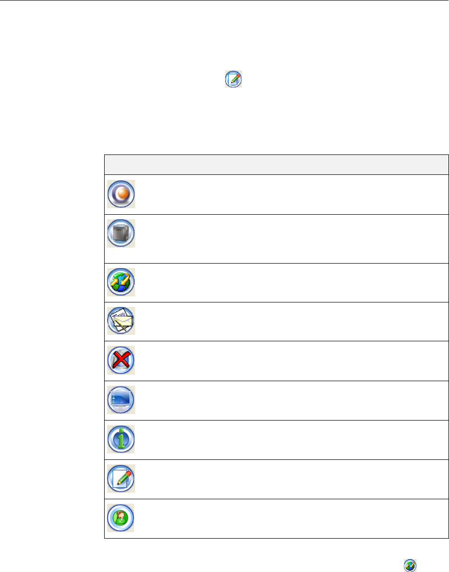
Using Job Manager
6–4
DOC-24000 Rev. A
Job Manager
Operations Evenaftersendingabuildtraytothe3‐Dprinter,youcaninspectthetray—
andmakechangestoit,ifnecessary—aslongasitisstillintheprintqueue.
To inspect the build tray:
1. Selectthejob.
2. ClicktheEditJobiconoropentheJobmenuandselectEdit.
ObjetStudioopens,displayingthebuildtray.Tomakechangestoit,see
“MakingchangestoaJob”onpage 6‐10.
ThefollowingoperationsareavailablefromtheclientJobManager
interface:
The3‐DprinterStatusscreenenablesclientstomonitortheprogressof
printingjobs.Todisplaythescreen,clicktheMachineStatusicon.
Icon Menu Option Purpose
3‐DPrinter>
NewJob LaunchesObjetStudio;topreparenewtrays.
3‐DPrinter>
SetPrinter Displaysanetwork‐browsingdialogbox,to
connecttoanObjetservercomputer.Tospecify
acomputer,itmustbeoperatingand
connectedtothelocalnetwork.
—— Displaysthestatusofthe3‐Dprinter(see
figure 6‐3).
3‐DPrinter>Report Displaysoptionsforusermessagesandalerts
(paperprinter,e‐mail,SMS—see“Configuring
UserAlerts”onpage 6‐5).
Job>Delete... Removestheselectedjobfromthequeue.
Job>View… Opensawindowdisplayingtheselectedtray.
Inthiswindow,youcanviewthetrayfrom
differentangles.
Job>Properties Opensawindowdisplayingthepropertiesof
theselectedmodel.
Job>Edit LaunchesObjetStudioandloadsthecurrent
tray,toenablemakingchangestothetrayafter
itissenttotheserverbutbeforeitisprinted.
Help>About... DisplaystheJobManagerversion.
DRAFT 4 - July 11, 2010
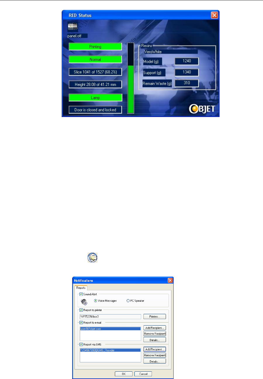
DOC-24000 Rev. A 6–5
Alaris30 User Guide
Figure 6-3: Printer status screen
Configuring
User Alerts JobManagercanalertyouandotherstothestatusofthejobssenttothe
serverforprinting.Thefollowingeventscanbereported:
•Thelevelofmodelorsupportmaterialislow.
•Thejobwasinterrupted.
•Thejobwascompletedsuccessfully.
Tosende‐mailandSMSmessages,makesurethate‐mailsoftware
supportingMAPIisinstalledontheprinter’sservercomputer.TosendSMS
messages,thecellularphoneservicemustsupportthetransmissionofe‐
mailmessagesbySMS.WithSMSalerts,onlythesubjectlineofthee‐mail
messageistransmitted.
Note: In the e-mail program, make sure the security settings are set to
“low” and add the server Job Manager to the “trusted” list (select
Tools > Options, Security tab).
To configure Job Manager to send notifications and alerts for your jobs:
1. ClickorselectNotificationsfromthe3‐DPrintermenu.
TheNotificationsdialogboxopens.
Figure 6-4: User alerts settings
DRAFT 4 - July 11, 2010
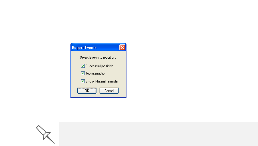
Using Job Manager
6–6
DOC-24000 Rev. A
2. Fore‐mailandSMSalerts,clickAdd Recipientintherespective
sections.
3. TochoosetheeventsreportedtoyoubyJobManager,clickDetailsin
therelevantsections.
Figure 6-5: Event selection for alerts
4. SelectthedesiredeventsforsendingalertsandclickOK.
The parameters for “Low level of material” alerts are set on the printer’s
server computer.
DRAFT 4 - July 11, 2010
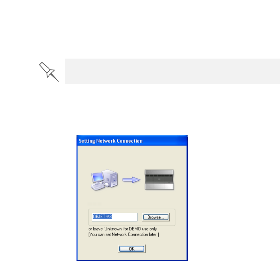
DOC-24000 Rev. A 6–7
Alaris30 User Guide
Server Job Manager
WhenyouopentheserverObjetStudio/JobManagerprogramforthefirst
time,oriftheprogramisnotconnectedtoanObjet3‐Dprinter,youare
promptedtoconnecttoaprinter.IfyouclickYesinthedialogbox,the
SettingNetworkConnectiondialogboxopens(seefigure 6‐6).
Youcanswitchtheserverconnectiontoanotherprinteratanytime.
To set (or change) the printer connection:
1. Fromthe3DPrintermenu,selectSet Printer.
2. IntheSetPrinterdialogbox,clickConnect...
Figure 6-6: Printer connection dialog box
3. Typethenameofthecomputerinsidetheprinter,orclickBrowseto
findandselectit.ClickOKtoclosethedialogbox.
To connect to a printer, the printer must be on and connected to the local
network.
DRAFT 4 - July 11, 2010
Using Job Manager
6–8
DOC-24000 Rev. A
Job Manager
Screen Onaservercomputer,JobManagerdisplaysthequeueofjobssenttoitby
allclientcomputers.Inaddition,itlistsdetailsofthelast15jobssenttothe
printer,andinformationaboutthejobcurrentlybeingprinted.
Figure 6-7: Server Job Manager screen
PrintQueue
Informationforeachofthequeuedjobsisdisplayed,includingthejob
status:
Print Queue
Print History
Current Job
Info
Status Meaning
Waiting Printingofthisjobhasnotstarted.
Building Printingofthisjobisinprogress.
Paused Printingofthisjobbegan,butwasinterruptedbythe
administratorbeforebeingcompleted.
Stopped Printingofthisjobwaspreviouslyterminatedbythe
administrator,andlaterputintheprintqueueagain.
Error Errorspreviouslyoccurredduringtheprintingofthisjob,
anditwasplacedintheprintqueueagain.
Editing Thisjobisnowbeingedited(withObjetStudio)onthe
Alarisservercomputer.
Previewing Theslicesofthisjobarebeingdisplayedinaseparate
window.
(Todisplaythejobtray,opentheJobmenuandselect
Preview Slices.)
Spooling ThejobfileisbeingspooledintheAlarisprinter.
Preprocessing TheAlarisprinterisreadyingitselfforprinting:thecover
locks,printheadswarmupandareputinstartingposition,
theUVlampisturnedon,build‐traylevelisadjusted.
DRAFT 4 - July 11, 2010
DOC-24000 Rev. A 6–9
Alaris30 User Guide
JobHistory
TheHistorysectionoftheJobManagerscreenlistsdetailsofthelast15jobs
sentforprinting,showingthejob’sfinalstatus.Ajobcanbereturnedfrom
theHistorysectiontotheprintqueueinordertoprintthetrayagain.
To move a job from History to the print queue:
1. SelectthejobintheHistorysection.
2. ClicktheResumeicon.
ThejobmovesfromtheHistorysectiontotheendoftheprintqueue.
Note: Alternatively, you can drag the job fromtheHistorysectiontothe
printqueue.
Job Manager
Operations Thefollowingtablesummarizesthemainoperationsavailablefromthe
serverJobManagerinterface.Manyoftheiconsareactiveonlyifajobis
selected.
To manipulate jobs in other ways, see “Job Manager Operations,” below.
Icon Menu Option Purpose
3‐DPrinter>
NewJob LaunchesObjetStudioforpreparingnewtrays.
3‐DPrinter>
SetPrinter Displaysanetwork‐browsingdialogbox,to
connecttoanObjetservercomputer.Tospecify
acomputer,itmustbeoperatingand
connectedtothelocalnetwork.
3‐DPrinter>
AddJob... Enablesyoutoloadpreviously‐savedjobs(objtf
files).
3‐DPrinter>Report Displaysoptionsforusermessagesandalerts
(paperprinter,e‐mail,SMS—see“Configuring
UserAlerts”onpage 6‐5).
——— Movestheselectedjobtotheheadoftheprint
queue.
——— Movesuptheselectedjobbyonestepinthe
printqueue.
Note:Itisrecommendedthatyougroup
togetherjobstobeprintedwiththesametype
ofmodelmaterial.Thisway,theneedfor
changingmodelmaterialbetweenjobsis
reduced.
——— Movesdowntheselectedjobbyonestepinthe
printqueue.
——— Movestheselectedjobtotheendoftheprint
queue.
DRAFT 4 - July 11, 2010
Using Job Manager
6–10
DOC-24000 Rev. A
Making
changes to a
Job
Fromthejob(“print”)queueofJobManager,youcanopenjobstomake
changestothembeforeprinting.
To make changes to a job:
1. Selectthejobintheprintqueue.
2. ClicktheEditJobiconoropentheJobmenuandselectEdit.
ObjetStudioopens,displayingthebuildtray.(Thestatusofthejobin
JobManagerchangesfrom“Waiting”to“Editing.”)
3. MakechangestothebuildtrayinObjetStudio(seechapter 5,“Using
ObjetStudio”).
4. InObjetStudio,savethechangesbyselectingFile > Save Tray(orby
pressingCtrl+S).
5. CloseObjetStudio.
ThestatusofthejobinJobManagerchangesbackto“Waiting.”
Job>RestartJob Forastoppedjobintheprintqueue:Starts
printingtheselectedjobfromthebeginning.
ForaselectedjobintheHistorysection:Moves
thejobtotheprintqueueandchangesitsstatus
toWaiting.
Job>Stop... Instructsthe3‐Dprintertostopprintingafter
curingthecurrentlyprintedslice.(Youcan
continueprintingwiththeResumeiconor
menuoption,butforshortinterruptions,use
thePauseiconormenuoption.)
Job>Pause... Instructsthe3‐Dprintertostopprintingafter
curingthecurrentlyprintedslice.(This
commanddoesnotflushtheprintingbuffer.
Therefore,useitinsteadofStopwhenyou
intendtocontinueprintingthejobshortly.)
Job>Resume Continuesprintingthecurrentjobafter
printingwasstoppedwiththeStoporPause
iconormenuoption.
Job>DeleteJob... Removestheselectedjobfromthequeue.
Job>ReviewJob… Opensawindowdisplayingtheselectedtray.
Inthiswindow,youcanviewthetrayfrom
differentangles.
Job>JobInfo… Opensawindowdisplayingthepropertiesof
theselectedmodel.
Job>EditJob… LaunchesObjetStudioandloadstheselected
tray,toenablemakingchangestoitbefore
beingprinted.(See“MakingchangestoaJob,”
below.)
Help>About... DisplaystheJobManagerversion.
Icon Menu Option Purpose
DRAFT 4 - July 11, 2010
DOC-24000 Rev. A 6–11
Alaris30 User Guide
User Alerts JobManagercanalertyouandotherstothestatusofthejobssenttothe
serverforprinting.Thisisespeciallyusefulduringlongprintingjobs,when
theoperatorisawayfromthe3‐Dprinter.Thefollowingeventscanbe
reported:
•Thelevelofmodelorsupportmaterialislow.
•Thejobwasinterrupted.
•Thejobwascompletedsuccessfully.
Fordetailsonhowtoconfigurealertmessages,see“ConfiguringUser
Alerts”onpage 6‐5.
To set parameters for “Low level of material” alerts:
1. Fromthe3‐DPrintermenu,selectMaterial Consumption….
2. Inthedialogboxthatopens,setthetimeorthematerialweight
remainingthattriggersthealertmessage.
Figure 6-8: Material alert message dialog box
ThedialogboxshownabovealsopopsupovertheJobManagerscreento
alerttheoperatorthatthereisnotenoughmaterialloadedintheprinterto
completethecurrentjob.Aslongasthisconditionexists,awarningicon
appearsinthelower‐rightcorneroftheJobManagerscreen(whenthe
statusbarisvisible).
Note: If the status bar is not visible, select it from the View menu.
DRAFT 4 - July 11, 2010
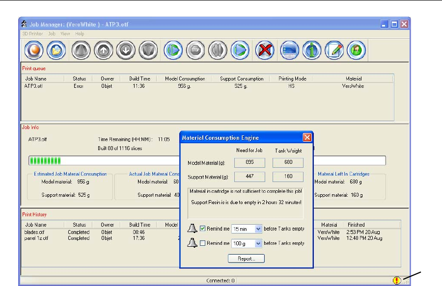
Using Job Manager
6–12
DOC-24000 Rev. A
Figure 6-9: Insufficient material warning
Whenthetimesetinthedialogboxtriggerstheremotealertmessage,the
warningiconchangescolor—fromayellowtoaredbackground.
Sending the
Tray to the 3-D
printer for
Production
Ifthereisajobintheprintqueue,itissentautomaticallytotheAlaris
printer—aslongasitison,thereisaconnectiontotheprinter,andthe
printerisonline.Chapter7describesstartingandoperatingtheAlaris
printer.
Material
warning
icon
DRAFT 4 - July 11, 2010

DOC-24000 Rev. A 7–1
Operating & Maintaining the
Alaris30 3-D Printer
StartingtheAlaris30Printer .............................................................. 2
LoadingModelandSupportCartridges.......................................... 3
ProducingModels ............................................................................... 5
PrinterInterfaceColor Key.................................................................. 7
PrintingIndicators ................................................................................ 8
ResumingProductionAfterPrintinghasStopped......................... 9
ChangingtheModelMaterial ......................................................... 10
KeepingtheAlarisPrinterinIdleMode........................................ 14
ShuttingDowntheAlarisPrinter ................................................... 15
ShutdownWizard ............................................................................... 15
MaterialFlush/FillWizard................................................................. 17
MaintainingtheAlarisPrinter ........................................................ 20
RoutineMaintenanceSchedule......................................................... 20
CleaningthePrintHeads................................................................... 21
PatternTest........................................................................................... 23
ImprovingPrintQuality .................................................................... 24
CleaningandReplacingtheWiper................................................... 24
CleaningandReplacingtheRollerWasteCollector ...................... 27
AligningthePrintHeads ................................................................... 30
ReplacingPrint Heads........................................................................ 34
CalibratingtheLoadCells ................................................................. 45
ReplacingtheOdorFilter................................................................... 47
ReplacingtheUVLamp ..................................................................... 48
ReplacingtheWasteContainer ......................................................... 53
CleaningtheExteriorPanels ............................................................. 55
Backing‐UpandRestoringPrinterSettings .................................... 56
ReInitiateWizard ................................................................................ 56
DRAFT 4 - July 11, 2010
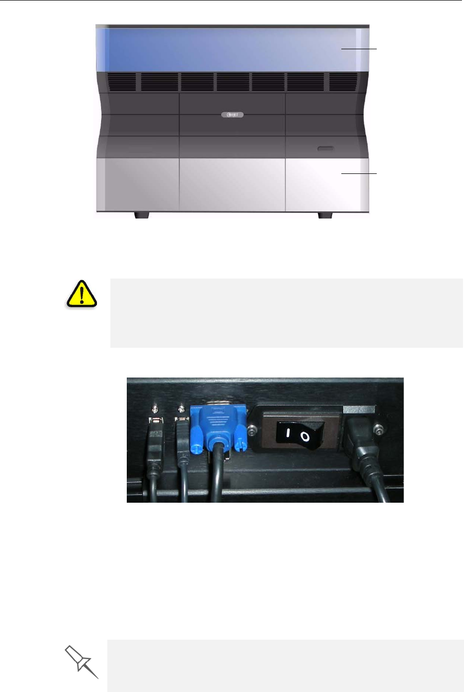
Operating & Maintaining the Alaris30 3-D Printer
7–2
DOC-24000 Rev. A
Figure 7-1: The Alaris30 3-D Printer
Starting the Alaris30 Printer
1. Turnonthemainpowerswitch,locatedatthebackoftheAlarisprinter.
Figure 7-2: Main power cable and switch
ThemainpowerswitchturnsontheAlarisprinter,whichincludesthe
built‐inAlariscomputer.
2. Afterthecomputerboots,logintoWindowsandlaunchtheAlaris
controlapplication:
•Onthecomputerdesktop,double‐clicktheAlarisprintericon.
or—
•FromtheStartmenu,selectObjet > Desktop.
Printer cover
Printing-materials &
waste compartment
CAUTION!
•Do not attempt to operate the Alaris printer before being trained by an
Objet customer-support representative.
•Observe all safety warnings and follow the safety guidelines described
in chapter 2.
A valid HASP key is required on the printer computer for the application to
open. This key should be installed during printer installation. If the
application does not open and a HASP message appears, contact your
dealer or Objet Customer Support.
DRAFT 4 - July 11, 2010
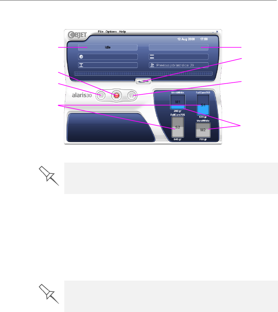
DOC-24000 Rev. A 7–3
Alaris30 User Guide
TheAlarisprinterinterfacescreenopens(seefigure 7‐3).Allmonitoring
andcontrollingoftheAlarisprinterisdonefromthisinterface.
Figure 7-3: Alaris30 interface
Loading Model and Support Cartridges
Alarisprintersusetwocartridgesofmodelmaterialandtwocartridgesof
supportmaterial,eachweighingonekilogramwhenfull.Agraphical
representationofthecartridgesandtheircurrentweightappearsinthe
printerinterface(seefigure 7‐3).
Note: The printer-control interface displays the type and weight of the
material cartridges loaded only if the printing-materials drawer is
closed.
To load model and support cartridges:
1. OnthefrontoftheAlarisprinter(seefigure 7‐1),pushtheprinting‐
materialsdrawertoreleaseitandpullitopen.
2. Ifyouarereplacingacartridge,removetheoldonebypullingit
straightup.
3. Loadmodelandsupportcartridgesintotheirrespectivecompartments
(seefigure 7‐4).
Printer mode
Support material
cartridges
Display
toggle button
Pause button
Stop button
Model material
cartridges
Current activity
Online/offline button
Alaris installations utilize one monitor for displaying both the computer
running Objet Studio / Job Manager and the computer installed inside the
printer. Make sure that the KVM (keyboard-video-mouse) switch is in the
correct position so that the Alaris printer interface is displayed.
If you need to replace the model material currently installed with another
type, see “Changing the Model Material” on page 7-10. Otherwise, make
sure to replace the model cartridge with one containing the same type of
material.
DRAFT 4 - July 11, 2010
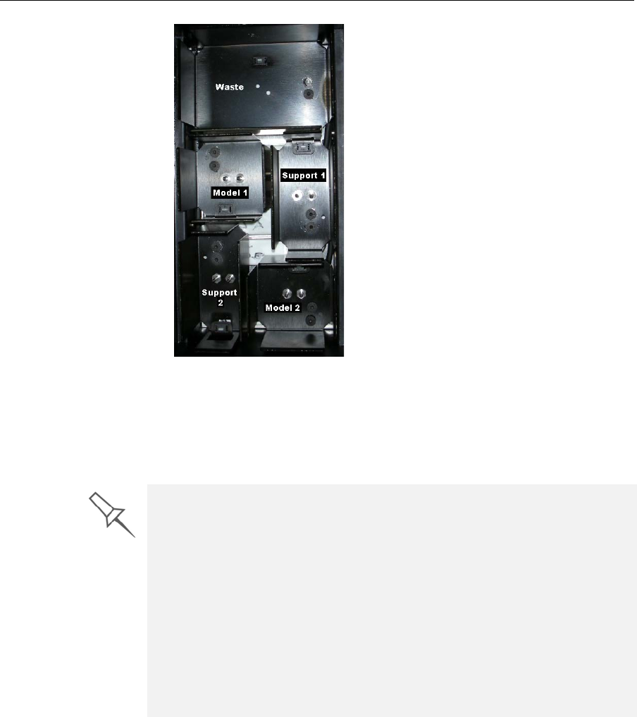
Operating & Maintaining the Alaris30 3-D Printer
7–4
DOC-24000 Rev. A
Figure 7-4: Printing-materials drawer
Youshouldfeelsomeresistance,asaneedlepiercesthecartridge.
4. ChecktheAlarisprinterinterfacetomakesurethatthenewcartridge
isdetectedandthatitsweightisdisplayed(seefigure 7‐3).
5. Closetheprinting‐materialsdrawer.
Tips about replacing cartridges:
•You can replace material cartridges either before or during printing. If
you do so while printing, make sure to load the new cartridge and close
the cartridge drawer within three minutes. This ensures that the print job
is not interrupted. (When the drawer is open, the cartridges are not
displayed in the printer interface.)
•You can replace partially used cartridges to avoid the need for replacing
them during printing. However, repeated removal and installation of a
cartridge can cause the material in it to leak. Therefore, it is
recommended that you re-install a used cartridge only once.
•You can load partially used cartridges, as long as they contain more
than 100 grams of material.
DRAFT 4 - July 11, 2010

DOC-24000 Rev. A 7–5
Alaris30 User Guide
Producing Models
Beforebeginningtoproducemodels,itisrecommendedthatyoucleanthe
printheads(see“CleaningthePrintHeads”onpage 7‐21).
To prepare the Alaris printer for producing models:
1. MakesurethatthebuildtrayintheAlarisprinterisemptyandclean.If
not,removeoldmaterialwiththescraper,andcleanthetray
thoroughlywithcleaningfluid.
2. Makesurethatthereissufficientmodelandsupportmaterialloaded
intheprinter,asindicatedintheAlarisprinterinterface(see
figure 7‐3).Youmaywanttoreplacethecartridgesofmodeland
supportmaterialcurrentlyloadedintheprintertoavoidtheneedfor
replacingthemduringprinting.
3. AtthebottomoftheAlarisprinterinterface,clicktheredbuttonto
switchtheprintertoonlinemode.
Thecolorofthebuttonchangesfromredtogreen(seefigure 7‐7).If
thereisajobintheJobManagerqueue,itissenttotheprinter.
CAUTION: Use protective gloves when cleaning the build tray, and be
careful of the sharp edges of the scraper blade.
Forinstallingmaterialcartridgesandreplacingemptyones,see
“LoadingModelandSupportCartridges”onpage 7‐3.
DRAFT 4 - July 11, 2010
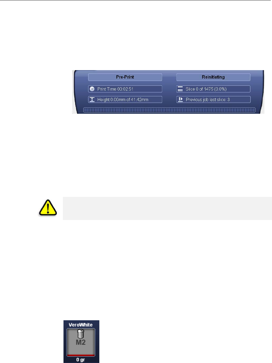
Operating & Maintaining the Alaris30 3-D Printer
7–6
DOC-24000 Rev. A
OntheAlarisprinterinterface,theprintermodechangesfromIdletoPre‐
print,astheprinter’scomponentspreparethemselvesforproduction:
•Theprintblockisheated.
•Ifmorethan48hourshavepassedsincethelastprintjob,theprinting
materialsintheprintheadsareflushedandreplaced,toensurequality
printing.(Thisstepadds7to14minutestothePre‐printcycle,anditis
displayedintheprinterinterface.)
Figure 7-5: ReInitiate process during the Pre-Print cycle
•TheUVlampispoweredanditwarmsup.
Whenprintingbegins,JobManagersendssevenslicestotheAlarisprinter.
ThisisthestandardbufferbetweentheJobManagerandtheprinter.As
eachsliceisprinted,theJobManagersendsanotherslicetotheprinter.
Dependingonthesizeofthemodel(s)tobeproduced,printingcantake
betweenseveralhourstoseveraldays.Aslongasthereisenoughmodel
andsupportmaterialinthesupplycartridges,printingproceeds
automaticallyuntilthejobisfinished.
TheAlarisprinterusesonemodel‐materialcartridgeandonesupport‐
materialcartridgetoproducemodels.Whenfourcartridgesareloadedin
theprinter,twoofthemarereserve,orstandby,cartridges.Bydefault,the
printerfirstusesthecartridgeswiththeleastmaterialinthem.
¾Theactivecartridgesareblueintheprinterinterface.
Whentheweightofacartridgedropsbelow100grams,theremaining
materialdisplayedintheprinterinterfaceisred.Theprinterthenalternates
thepumpingofmaterialbetweentheheavierandthealmost‐empty
cartridge.Thisisindicatedintheprinterinterfacebyanhour‐glassicon.
(SeeFigure 7‐8onpage 8.)
Whenacartridgeiscompletelyempty,atrashiconisdisplayed.
Figure 7-6: Empty cartridge indicator
Youcanmonitorprinterstatusindicatorsbyswitchingtheprinterinterface
display.Todothis,clickthedisplaytogglebuttonintheprinterinterface
screen.
During printing, the server computer must remain on and it must
communicate with the Alaris printer. Do not log-off Windows until printing is
finished.
DRAFT 4 - July 11, 2010
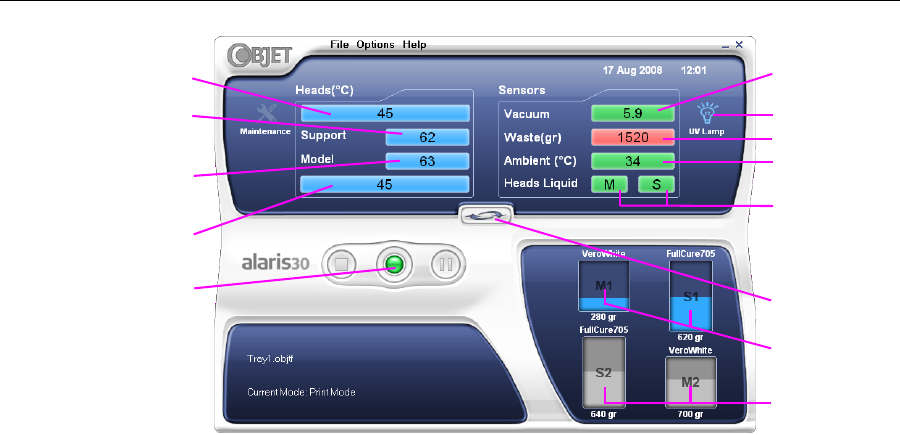
DOC-24000 Rev. A 7–7
Alaris30 User Guide
Figure 7-7: Alaris printer indicators
Printer
Interface
Color Key
Thebackgroundcolorsintheprinterindicatorfieldstellyouataglance
whetherornotthevalueoritemissuitableorreadyforprinting.
•Green—suitable/readyforprinting
Forexample,infigure 7‐7:
Ambient—Theambienttemperatureoftheprintingchamberis
withintheacceptablerange.
HeadsLiquid—Thelevelofmodelandsupportmaterialintheprint‐
blockreservoirisOK.
Vacuum—Thevacuumlevelinthesystemiswithintheacceptable
range.
•Red—notsuitableforprinting(orindicatesawarning)
Forexample,infigure 7‐7:
Waste—Theweightofthewastecontaineris1520grams,morethan
allowedwhenbeginningaprintjob.(See“ReplacingtheWaste
Container”onpage 7‐53.)
•Blue—notready
Forexample,infigure 7‐7:
UVlamp—TheUVlampisnoton.
Heads(°C)—Theheadshavenotreachedthetemperaturerequired
forprintingmodels(inprintingmode).
Thecolorofthematerialcartridgesdisplayedintheprinterinterface
indicateswhichcartridgesareactiveforthecurrent(ornext)printjob.
•Blue—activecartridges
•Gray—reservecartridges
Block temp.
in front of
print heads
Block temp.
behind
print heads
Display
toggle button
Temp. of
support head
Printer set to
online mode
(green)
System
vacuum level
Chamber temp.
Model/Support
material in print-
block reservoir
Temp. of
model head
Waste weight
UV lamp state
Active material
cartridges (blue)
Reserve material
cartridges (gray)
DRAFT 4 - July 11, 2010
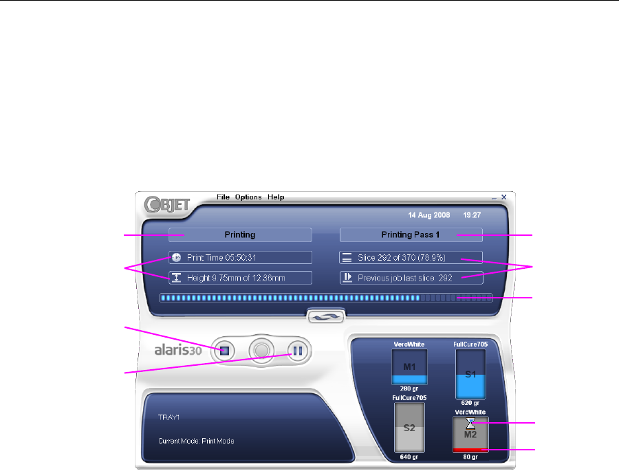
Operating & Maintaining the Alaris30 3-D Printer
7–8
DOC-24000 Rev. A
Printing
Indicators TheprinterinterfacescreenchangeswhenyousendaprintjobfromJob
Managertotheprinter,andtheprinterisonline(seefigure 7‐8):
•ThemodechangesfromPre‐printtoPrinting.
•Thespecificactivitybeingperformedisshowninthe“currentactivity”
field.
•Currentjob‐printinginformationisdisplayed.
•Theprintingprogressbarisdisplayed.
•TheStopandPausebuttonsareenabled.
Figure 7-8: Alaris printer interface during printing
Progress bar
Stop button
Printer mode
Job information
Current Activity
Job information
Distributed
pumping
Almost empty
Pause button
DRAFT 4 - July 11, 2010
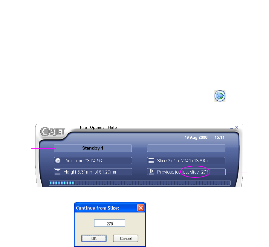
DOC-24000 Rev. A 7–9
Alaris30 User Guide
Resuming Production After Printing has Stopped
Iftheprintingprocessisinterruptedforanyreason,JobManagerstops
sendingslicestotheAlarisprinter.
To continue printing the model:
1. Switchtheprintertoonlinemodebyclickingtheredbuttonatthe
bottomoftheAlarisprinterinterface(seefigure 7‐3onpage 7‐3).
Thebuttonchangesfromredtogreen(seefigure 7‐7onpage 7‐7).
2. MakesurethatthecomputernetworkconnectingtheprinterandJob
Managerserverisactive.
3. IntheJobManagerinterface,clicktheResumeicon.
4. IntheContinuefromSlicedialogboxthatappears,confirmtheslice
number,aftercheckingtheAlarisprinterinterface.
Figure 7-9: Alaris printer interface after interrupted printing
Figure 7-10: Continue from Slice confirmation dialog box in server
(Job Manager) interface
5. If,foranyreason,thecorrectnumberdoesnotappearinthedialog
box,enterthenumberandclickOK.
Youcannotcontinueprintingthemodelif:
•ThenumberofthelastsliceprinteddoesnotappearintheAlaris
printerinterface,eveniftheservercomputerdisplaystheContinuefrom
Sliceconfirmationdialogbox.
•Therewasarelativelylonginterruptioninprinting,evenifthe“last
slice”and“continuefromslice”indicatorsarecorrect.Thepartofthe
modelalreadyprintedmaydeformorshrink,andtheremightbea
visibledifferencebetweenitandthenewlyprintedpart.Theeffectsofa
printingstoppageonamodeldependonthemodelsizeandstructure,
modelmaterialused,ambienttemperatureandthelengthofthe
stoppage.
Printer mode
Last slice
printed
DRAFT 4 - July 11, 2010
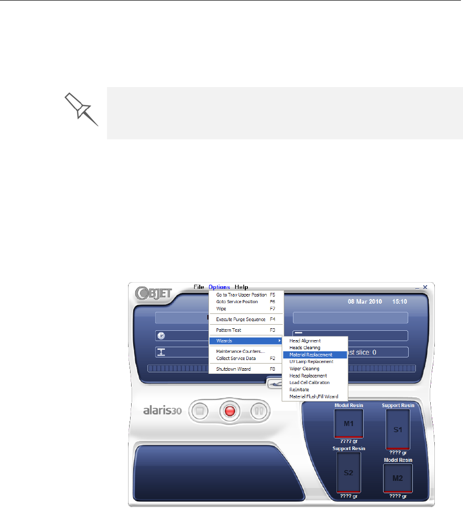
Operating & Maintaining the Alaris30 3-D Printer
7–10
DOC-24000 Rev. A
If you cannot continue printing:
1. CanceltheprintjobinJobManager.
2. Removethepartiallyprintedmodelfromthebuildtray.
3. SendthejobtotheAlarisprinteragain.
Changing the Model Material
Beforeproducingmodelsusingadifferenttypeofmodelmaterialthanis
currentlyinstalled,runtheMaterialReplacementwizardtoflushtheprint
blockandfeedtubes.
To replace the model material:
1. StarttheMaterialReplacementwizardfromtheOptionsmenu.
2. Intheopeningscreen,clickNext.
3. Iftheprintercoverisnotclosed,ascreenappearsinstructingyouto
closethecover.ConfirmthatitisclosedandclickNext.
You can stop and later resume printing from either the Alaris printer
interface or the Job Manager interface, since both applications are updated
when you use these commands. However, after clicking the Pause button in
the printer interface, you can only resume printing from the printer interface.
DRAFT 4 - July 11, 2010
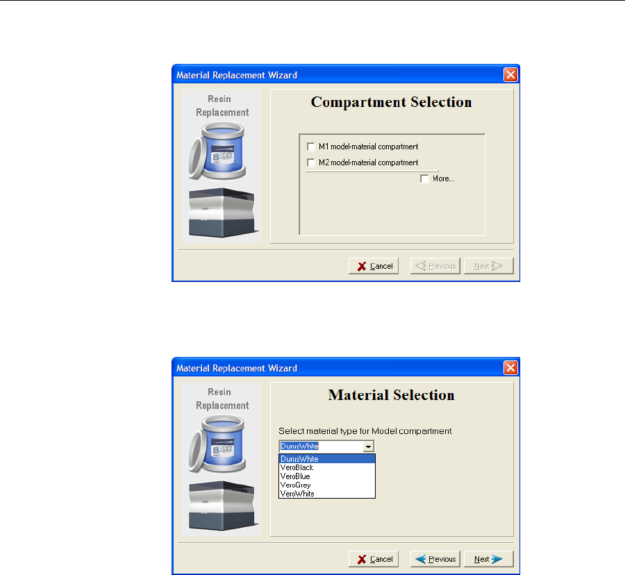
DOC-24000 Rev. A 7–11
Alaris30 User Guide
4. IntheCompartmentSelectionscreen,selectthecartridge(s)youwantto
replace,andclickNext.
Figure 7-11: Compartment Selection screen
5. Fromthedrop‐downmenu,choosethematerialyouwanttoinstall,
andclickNext.
Figure 7-12: Material Selection screen
Note: This selection automatically affects the default material setting in
Objet Studio.
DRAFT 4 - July 11, 2010
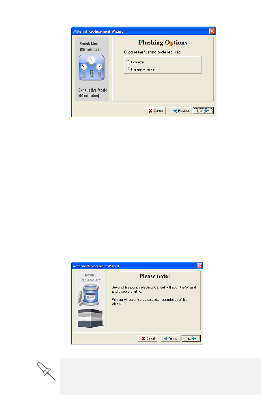
Operating & Maintaining the Alaris30 3-D Printer
7–12
DOC-24000 Rev. A
6. IntheFlushingOptionsscreen,choosetheappropriatecycleforthe
modelmaterialyouwanttoinstall.
Figure 7-13: Flushing Options screen
•Economy.Duringthiscycle,whichtakesabout25minutes,the
pumppurgesthemodelmaterialfromtheprintblock,thenflushes
thesystemwiththenewmaterial.
Sincetracesofthepreviousmaterialmaybepresentinthefirst
modelsprintedwiththenewmaterial,thiscycleisusually
acceptablewhenreplacingalight‐coloredmodelmaterialwitha
darkermaterial(suchasVeroBlack™),oriftheexactcolorofthe
printedmodelsisunimportant.However,thiscycleensuresthat
modelswillhavethemechanicalpropertiesofthenewmaterial.
•High‐performance.Duringthiscycle,whichtakesabout60minutes,
thewizardcleansthefeedtubesandprintblockmorethoroughly
byflushingthesystemwithmorematerial.
Thiscycleensuresthatmodelswillhavethecolor(andthe
mechanicalproperties)ofthenewmaterial,whenreplacingadark‐
coloredmaterial(suchasVeroBlack)withalighter‐coloredmaterial.
7. ClickNext,andtakenoteofthewarningscreen.
Figure 7-14: Material Replacement warning screen
Once you start this procedure, you must complete it before you can produce
models with the Alaris printer. To perform the procedure at another time,
click Cancel. If you continue (by clicking Next) and you do not complete the
procedure, you must start the Material Replacement wizard again before
producing models.
DRAFT 4 - July 11, 2010
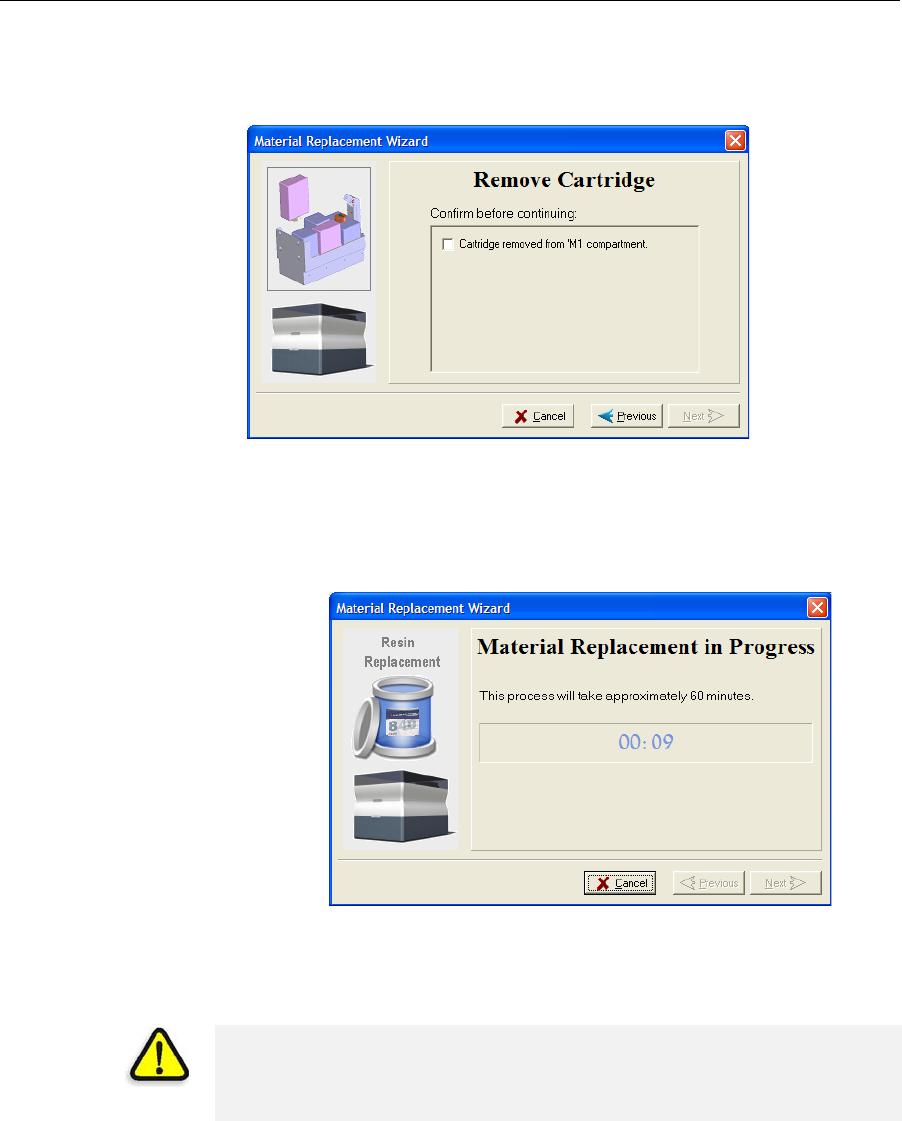
DOC-24000 Rev. A 7–13
Alaris30 User Guide
8. Tocontinue,clickNext.
9. Whenpromptedbythewizardscreen,removethematerialcartridges.
Selectthecheckboxtoconfirmthatyouhavedoneso,andclickNext.
Figure 7-15: Remove Cartridge confirmation screen
10. Whenprompted,loadthenewcartridge(s)andclosethedrawer.
ConfirmthisinthewizardscreenandclickNext.
Afteridentifyingthenewcartridge(s),theAlarisprinterbeginsfilling
theprintheadswiththenew
material.
Figure 7-16: Material replacement: filling heads with new material
11. Whenthefinalwizardscreenappears,makesurethatthescreen
displaysthenewly‐loadedmaterial(s).ClickDonetoclosethewizard.
Theprinter‐controlinterfaceisautomaticallyupdated,andshould
displaythenewmaterials.TheObjetStudiointerface(ontheprinter‐
serverworkstation)isalsoupdated,anddisplaysthenewmaterials.
CAUTION: Dispose of all material cartridges in accordance with all
applicable laws and regulations. If necessary, the cartridges can be
disassembled for recycling. If this is done, protect the person handling the
cartridges from direct exposure to uncured resins.
DRAFT 4 - July 11, 2010
Operating & Maintaining the Alaris30 3-D Printer
7–14
DOC-24000 Rev. A
Keeping the Alaris Printer in Idle Mode
Betweenprintingjobs,theAlaris30printercanbekeptonforuptoone
week.Iftheprinterwillnotbeusedformorethanaweek,usethe
shutdownwizardtoautomaticallyperformtheproceduresthatmustbe
donebeforeturningofftheprinter(see“ShuttingDowntheAlarisPrinter,”
below).
WhentheAlaris30printerstopsproducingmodels,theprintersoftware
automaticallyreducesthetemperatureoftheprintheadsasfollows:
Note: The printer mode is indicated in the green field on the left of the
interface (see figures 7-3, 7-7 and 7-8 on pages 3, 7 and 8).
If,afterprintingajob,youknowthattheprinterwillnotbeusedfor10
hoursormore,youcanimmediatelyturnofftheheatingoftheprintheads
byputtingtheprinterintoIdlemode.
To put the printer into Idle mode:
¾FromtheFilemenu(intheprinterinterface)clickExit.
Note: The printer remains in Idle mode until you open the Alaris printer
application and begin printing again.
Time after printing Mode Change in heating of print heads
first15minutes Standby1none
next5minutes Standby2heatingreduced(toroomtemp.)
after10hours Idle heatingstopped
When the printer is in Idle mode, do not turn it off. It can remain in this
mode—with the cover closed—for up to a week. For longer periods, shut
down the printer by running the Shutdown wizard (see below).
DRAFT 4 - July 11, 2010
DOC-24000 Rev. A 7–15
Alaris30 User Guide
Shutting Down the Alaris Printer
YouonlyneedtoshutdowntheAlarisprinterifitwillnotbeusedfora
weekormore.Otherwise,theprintercanremainon,inIdlemode.To
properlyshutdown,theprinterneedstoperformseveralprocesses.Donot
attempttoshutdowntheprinterbysimplyclosingthecomputer
interface(theprinter‐controlapplication),andneverdisconnectpowerto
theprinterbeforecompletingthiswizard.Instead,usethewizardsthat
preparetheprinterforshutdown.
•ShutdownWizard.Thiswizardclearstheprintheadsofprinting
materialsbeforeshutdown.
Usethiswizardifyouneedtoshutdowntheprintercomputer(or
disconnectthepowersuppliedtotheprinter)forlessthanoneweek,
andtocompletetheshutdownprocessafterrunningtheMaterial
Flush/FillWizard.
•MaterialFlush/FillWizard.Thiswizardreplacesprintingmaterialsin
theprintheadswithcleaningfluid.
Usethiswizardifyouneedtoshutdowntheprinterformorethanone
week.(Afterusingthiswizard,youmustrunitagainbeforeprinting
models,thistimetoreplacethecleaningfluidintheprintheadswith
printingmaterials.)TheMaterialFlush/FillWizardisdescribedon
page 7‐17.
Shutdown
Wizard Note: If you expect the printer to be shut down for more than one week, first
run the Material Flush/Fill Wizard (see page 7-17).
To run the Alaris Shutdown Wizard:
1. SelectShutdown Wizard fromtheOptionsmenu,orpressF8.
Figure 7-17: Shutdown wizard, opening dialog box
2. Intheopeningwizardscreen,clickNext.
Note: Run wizard manually is selected by default. It is recommended that
you do not change this selection, to have more control over the shutdown
process. If you select Run wizard unattended, the shutdown process may
take longer, and the wizard will automatically shut down the printer
computer.
DRAFT 4 - July 11, 2010
Operating & Maintaining the Alaris30 3-D Printer
7–16
DOC-24000 Rev. A
3. Inthenextscreen,indicatewhetherornotthetrayisemptyandclick
Next.
Figure 7-18: Tray status screen
Theshutdownprocedurebegins.
Figure 7-19: Shutdown progress screen
Theshutdownproceduremaytakeupto10minuteswhilethe
followingtasksareperformed:
a. Theprintblockreturnstoitsstartingpointonallaxes.
b. Theprintheadsareheated.
c. Theprintheadsareclearedofanyremainingmaterial.
Afterthesetasksarecompleted,thefinalwizarddialogboxappears,in
whichyouchoosewhetherornottoshutdownthecomputerinthe
Alarisprinteratthistime.
Figure 7-20: Computer Shutdown confirmation dialog box
DRAFT 4 - July 11, 2010
DOC-24000 Rev. A 7–17
Alaris30 User Guide
4. WhencompletelyshuttingdowntheAlarisprinterandturningthe
poweroff,selectYesandclickNext.
5. Aftertheprintercomputershutsdown,turnoffthemainpowerswitch
(atthebackoftheprinter)(seefigure 7‐2onpage 7‐2).
Material
Flush/Fill
Wizard
Youusethiswizardtopreparetheprinterforashutdownofmorethanone
week,andtorestoretheprintertoworkingcondition.
•Topreparetheprinterforanextendedshutdown,thewizarddrains
printingmaterialsfromtheprintheads,thenflushesthesystemwith
cleaningfluid.Thisprocesstakesabout60minutes.
Forthisprocedure,youneedtoloadfour(4)cleaning‐fluidcartridgesin
thecartridgedrawer.
•Torestoretheprintertoworkingcondition,thewizardfillsthesystem
withprintingmaterials.Thisprocesstakesabout30minutes.
Forthisprocedure,youneedtoloadtwo(2)cartridgesofmodel
materialandtwo(2)cartridgesofsupportmaterial.
To run the Material Flush/Fill Wizard:
1. SelectMaterial Flush/Fill Wizard fromtheOptionsmenu.
2. Intheopeningscreen,clickNext.
Figure 7-21: Wizard procedure selection
3. Selecttherequiredprocedure,andclickNext.
Note: Before continuing, make sure the required cartridges of material are
available for the procedure selected.
DRAFT 4 - July 11, 2010
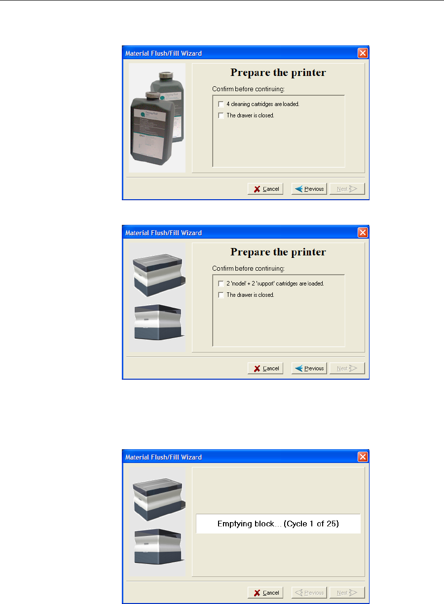
Operating & Maintaining the Alaris30 3-D Printer
7–18
DOC-24000 Rev. A
4. Loadtherequiredcartridges,closethecartridgedrawer,andconfirm
thisinthewizardscreen.
Figure 7-22: Cartridge confirmation screen—before shutdown
Figure 7-23: Cartridge confirmation screen—before printing
5. Inthenextwizardscreen,confirmthattheprintercoverisclosed,and
clickNext.
Thewizardrunsthematerial‐flushingcycles.
Figure 7-24: Flushing cycles in progress
DRAFT 4 - July 11, 2010
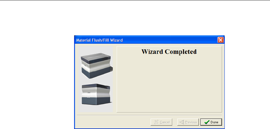
DOC-24000 Rev. A 7–19
Alaris30 User Guide
6. Ifcleaning‐fluidcartridgesareloadedintheprinter,thewizard
promptsyoutoremovethem.Confirmthisinthewizardscreen,and
clickNext.
Figure 7-25: Final wizard screen
Note: After preparing the printer for an extended shutdown period with this
wizard, run the Shutdown Wizard to complete the shutdown process.
DRAFT 4 - July 11, 2010

Operating & Maintaining the Alaris30 3-D Printer
7–20
DOC-24000 Rev. A
Maintaining the Alaris Printer
Theperformanceofroutinemaintenancetasksisessentialforgetting
satisfactoryresultsfromAlaris3‐Dprinters.Performthetasksatspecified
intervalsforoptimumperformance.
Routine
Maintenance
Schedule
Frequency Task For More Information
Aftereveryprintjob Cleantheprintheads.
Cleanthebuildtrayand
thesurroundingarea.
See“CleaningthePrint
Heads”onpage 7‐21.
Weekly PerformthePatterntest. See“PatternTest”on
page 7‐23.
Weekly Cleanandinspectthe
wiper. See“Cleaningand
ReplacingtheWiper”
onpage 7‐24.
Weekly RestarttheAlarisprinter
computerandtheserver
computer.
Monthly Cleantherollerwaste
collector. See“Cleaningand
ReplacingtheRoller
WasteCollector”on
page 7‐27.
Monthly,andafter
replacingprintheads Checkthealignmentof
theprintheads. See“AligningthePrint
Heads”onpage 7‐30.
Everysixmonths Replacetherollerwaste
collector. See“Cleaningand
ReplacingtheRoller
WasteCollector”on
page 7‐27.
Every500hoursof
printing,oronceevery
sixmonths
Calibratetheloadcells. See“Calibratingthe
LoadCells”on
page 7‐45.
Every2000hoursof
printing,oronceayear
Preventivemaintenance
visitbyauthorized
serviceengineer.
ContactyourObjet
supportcenter.
Onceayear Inspecttheactivated‐
carbonodorfilter,and
replaceifnecessary.
See“Replacingthe
OdorFilter”on
page 7‐47.
DRAFT 4 - July 11, 2010
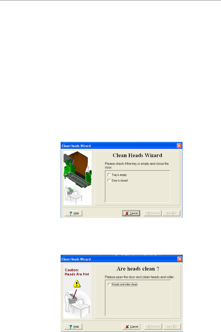
DOC-24000 Rev. A 7–21
Alaris30 User Guide
Cleaning the
Print Heads Periodicinspectionandcleaningoftheorificeplatesonthebottomofthe
printblockensuresthattheprintnozzlesarenotclogged.Awizardguides
youthroughtheprocedure,andadjustscomponentsoftheAlarisprinterto
enableyoutoperformit.TomaintainyourAlarisprinterinoptimum
condition,cleantheprintheadsaftereveryprintjob,whenyouremovethe
modelfromthebuildtray.Thisproceduretakesabout20minutes.
To clean the print heads:
1. Prepare—
•isopropanol(IPA—isopropylalcohol)orethanol(ethylalcohol)
•disposablecleaninggloves
•anObjet‐suppliedcleaningclothorequivalent
•amirror
2. StarttheHeadsCleaningwizardfromtheOptionsmenu(see
figure 7‐33onpage 7‐25).
3. Followtheinstructionsonthewizardscreens,andselectthecheck
boxestoconfirmthat:
•youhavecheckedthatthetrayisempty.
•youhaveclosedthecover.
Figure 7-26: Head cleaning procedure—wizard screen
4. ClickNext.
Theprinterpreparesforyoutocleantheprintheads.
5. Whenthefollowingscreenappears,openthecover.
Figure 7-27: Head cleaning wizard—steps 5–10
DRAFT 4 - July 11, 2010
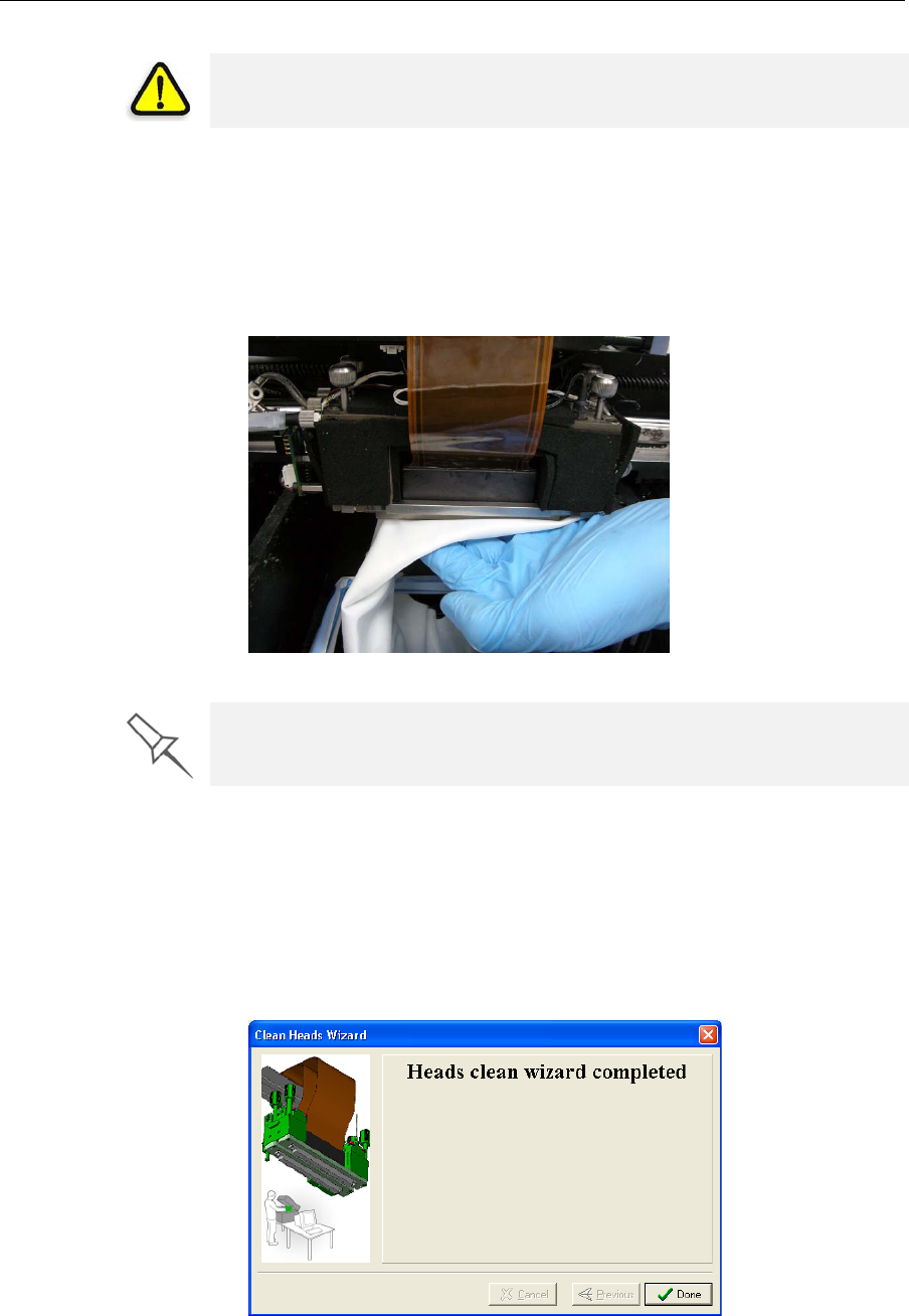
Operating & Maintaining the Alaris30 3-D Printer
7–22
DOC-24000 Rev. A
6. Placethemirroronthebuildtray.
7. Putonthegloves.
8. Soakthecleaningclothwiththecleaningfluid.
9. Cleantheorificeplates,withaback‐and‐forthmotion(seefigure 7‐28).
Usethemirrortomakesurethatyouhaveremovedalloftheresidue
material.
Figure 7-28: Cleaning the heads
10. Whenyouhavefinishedcleaning,selecttheconfirmationcheckboxin
thewizardscreen(seefigure 7‐27)andclickNext.
11. Removethecleaningmaterialsfromtheprinterandclosethecover.
12. Selecttheconfirmationcheckboxesinthewizardscreenandclick
Next.
Thehead‐purgecyclebegins.Whenthisiscomplete,thefinalwizard
screenappears.
Figure 7-29: Head cleaning wizard—final screen
13. ClickDonetoclosethewizard.
WARNING: The print head orifice plates (bottom surface) may be hot.
Do not touch them with your bare hands, and proceed with caution.
It is recommended that you use this opportunity to also clean the roller and
the UV-lamp lens (to the right of the print heads).
DRAFT 4 - July 11, 2010
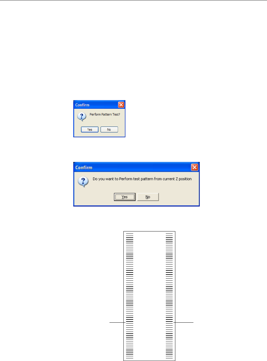
DOC-24000 Rev. A 7–23
Alaris30 User Guide
Pattern Test Thepatterntestisthebasicverificationoftheprinter’sabilitytoproduce
qualitymodels,sinceitdemonstratestheconditionofthenozzlesinthe
printheads.Makesure,therefore,thatyouperformthistestweekly,and
wheneveryoususpectaprintingproblem.
To perform the pattern test:
1. Makesurethatthebuildtrayisempty.
2. Prepareasheetofpinkpaper,approximately21×14centimetersin
size(8.5×5.5inches)—halfofthestandardA‐4orLettersize.
3. IntheAlarisprinter,tapethepinkpapertothecenterofthebuildtray.
4. PressF3,oropentheOptionsmenuandselectPattern Test.
Figure 7-30: Pattern Test confirmation
5. Inthefollowingdialogbox,clickNo.
Figure 7-31: Build tray (Z) level adjustment
TheAlarisprinterprintsaseriesoflinesonthetestpaper.
Figure 7-32: Sample Pattern Test
6. Carefullyinspectthetestpapertoseeiftherearemissinglines.
Lines printed by
model-material
print head
Lines printed by
support-material
print head
DRAFT 4 - July 11, 2010

Operating & Maintaining the Alaris30 3-D Printer
7–24
DOC-24000 Rev. A
Toomanymissinglines,especiallyiftheyareinthesamearea,
indicatesthatthequalityofprintingwhenproducingmodelswillbe
poor.Ifthisisthecase,see“ImprovingPrintQuality,”below.
Note: Acceptable model quality is subjective, and depends on the type
and scale (size) of the models produced. As a rule, however, if two
consecutive lines are missing, or if there are more than 10 lines missing in
either column, the model quality is usually unacceptable.
Improving
Print Quality Ifyoususpectthatprintqualityispoor,performthepatterntest(see
“PatternTest”).Iftheresultsarepoor,usethefollowingprocedureto
improveprintquality.
If the results of the last pattern test are poor:
1. FromtheOptionsmenu,selectExecute Purge Sequence,orpressF4.
2. Intheconfirmationdialogbox,clickYes.
Theprintheadsarepurgedofmodelandsupportmaterial,andthe
wiperremovesexcessmaterialfromthem.
3. Repeatthepurgesequence.
4. Performthepatterntest.
If the results of the pattern test are still poor:
1. Manuallycleantheprintheads(see“CleaningthePrintHeads”on
page 7‐21).
2. Performthepurgesequence.
3. Performthepatterntest.
If the results of the pattern test are still poor:
1. Carefullycleantheprintheadsagain,makingsurethereisnoresidue
leftonthem.
2. Performthepurgesequence.
3. Performthepatterntest.
If the results of the pattern test are still poor:
¾Replacefaultyprintheads(see“ReplacingPrint Heads”onpage 7‐34).
Cleaning and
Replacing the
Wiper
Arubberwiperremovesexcessmaterialfromtheprintheadsafterthe
purgesequence.Thisisdoneautomaticallybeforeeachprintjob,and
performedmanuallyduringmaintenancetasks.Youshouldcleanthe
wiperandsurroundingareaatleastonceaweek.Ifthewiperisdamaged
orworn,replaceit.
To inspect and clean the wiper:
1. Prepare—
•isopropanol(IPA—isopropylalcohol)orethanol(ethylalcohol)
•disposablecleaninggloves
•anObjet‐suppliedcleaningclothorequivalent
•asparewiper
•anM2.5Allenkey
DRAFT 4 - July 11, 2010
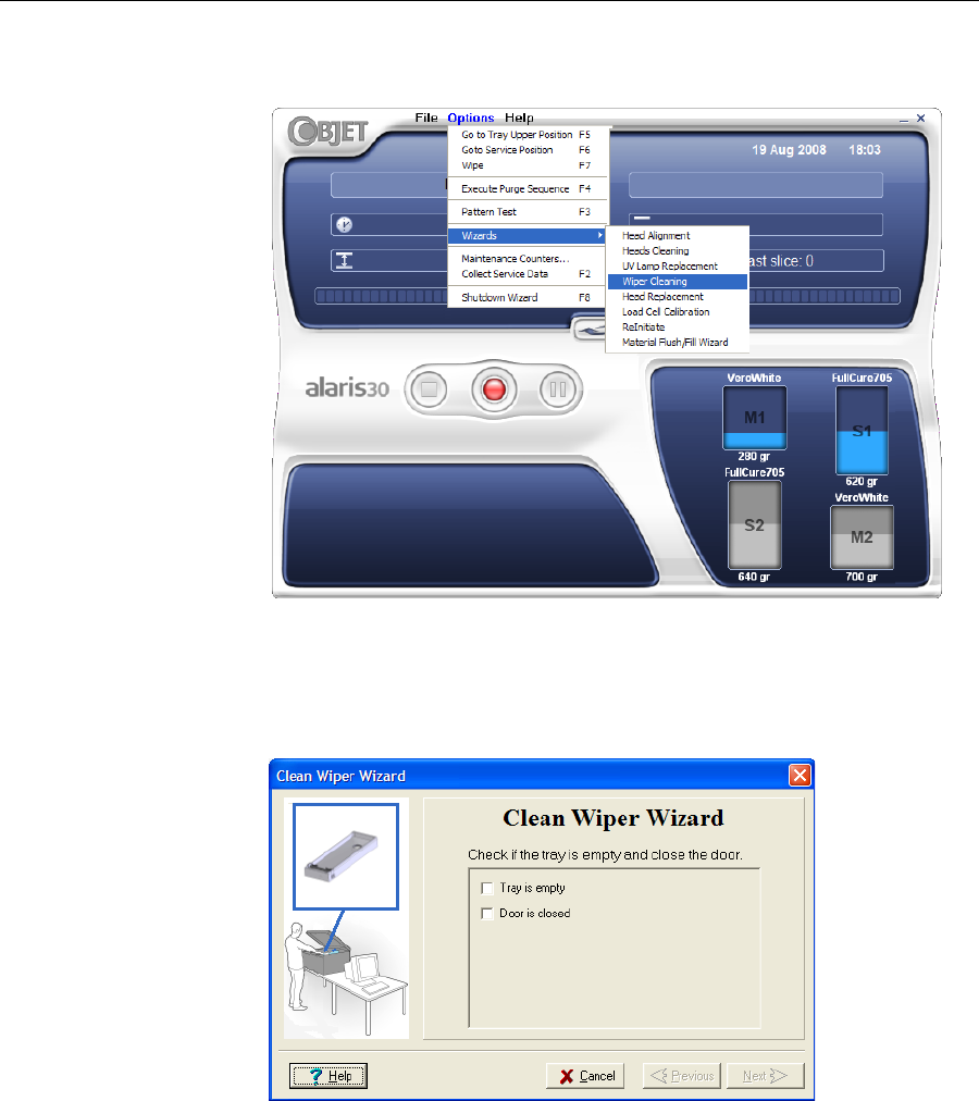
DOC-24000 Rev. A 7–25
Alaris30 User Guide
2. StarttheWiperCleaningwizardfromtheOptionsmenuoftheprinter
interface.
Figure 7-33: Starting the Wiper Cleaning wizard
3. Closetheprintercover,andclickNextinthewizardscreen.
4. Makesurethatthebuildtrayisempty,andclosetheprintercover.
Confirmthisinthewizardscreen.
Figure 7-34: Wiper Cleaning procedure—step 4
5. ClickNext.
DRAFT 4 - July 11, 2010
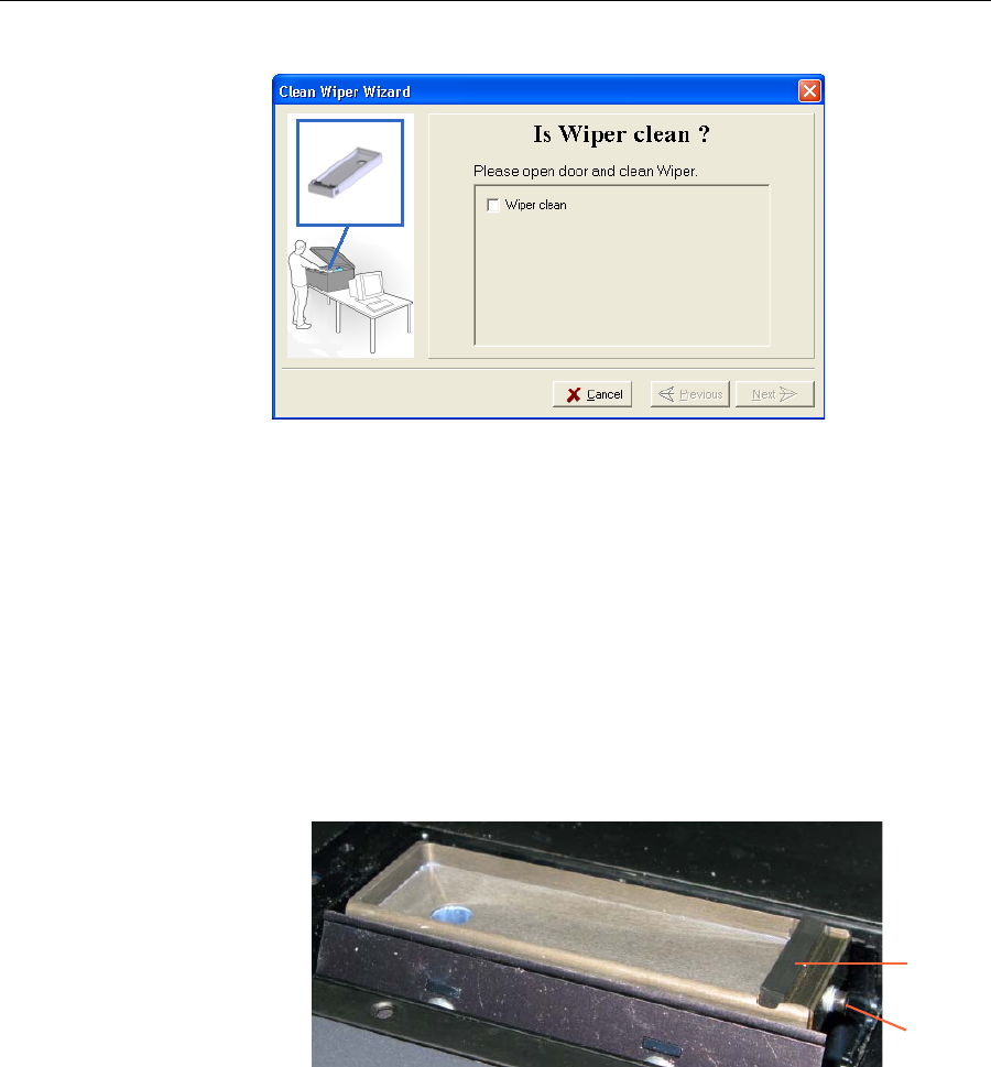
Operating & Maintaining the Alaris30 3-D Printer
7–26
DOC-24000 Rev. A
6. Whenthefollowingscreenappears,openthecover.
Figure 7-35: Wiper Cleaning wizard during steps 7–10
7. Putonthecleaninggloves.
8. Usingagenerousamountofcleaningfluidandthecleaningcloth,
removeanymaterialremainingonthewiperandthesurrounding
area.
9. Inspectthewiper.
Ifthewiperisscratched,tornorworn,orifyoucannotcleanit
completely,replaceit.Toensurethatmodelqualityisnotreducedover
time,youshouldreplacethewiperatleastonceamonth,evenifyoudo
notnoticeanywear.
a. WiththeM2.5Allenkey,loosen(butdonotremove)thescrew
securingthewiper.
Figure 7-36: Wiper and excess-material drain
b. Graspthewiperunitandremoveit.
c. Insertthenewwiper,makingsurethatitislevel,andtightenthe
securingscrew.
10. Inthewizardscreen(seefigure 7‐35),confirmthatthewiperbladeis
clean,andclickNext.
11. Makesurethatyouhaveremovedalltoolsandcleaningmaterials
fromtheprinter,andclosethecover.
Wiper
Securing
screw
DRAFT 4 - July 11, 2010
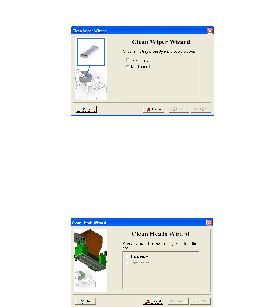
DOC-24000 Rev. A 7–27
Alaris30 User Guide
12. Selecttheconfirmationcheckboxesinthewizardscreenandclick
Next.
Figure 7-37: Wiper Cleaning procedure—final confirmation screen
13. ClickDonetoclosethewizard.
Cleaning and
Replacing the
Roller Waste
Collector
Youshouldremovetherollerwastecollectoronceamonthtocleanitand
toinspecttheconditionofthescraper.Theunitshouldbereplacedevery
sixmonths,orwhentherollerknifeiswornordamaged.
To remove the roller waste collector:
1. FromtheOptionsmenu,selectWizards>Heads Cleaning.
Thiswizardpreparestheprinterforremovingtherollerwaste
collector.
2. Whenthefollowingscreenappears,confirmthatthetrayisemptyand
thattheprintercoverisclosed,thenclickNext.
Figure 7-38: Wizard confirmation screen
Theprintblockmovestothecenterofbuildtray,andthetraylowers.
DRAFT 4 - July 11, 2010
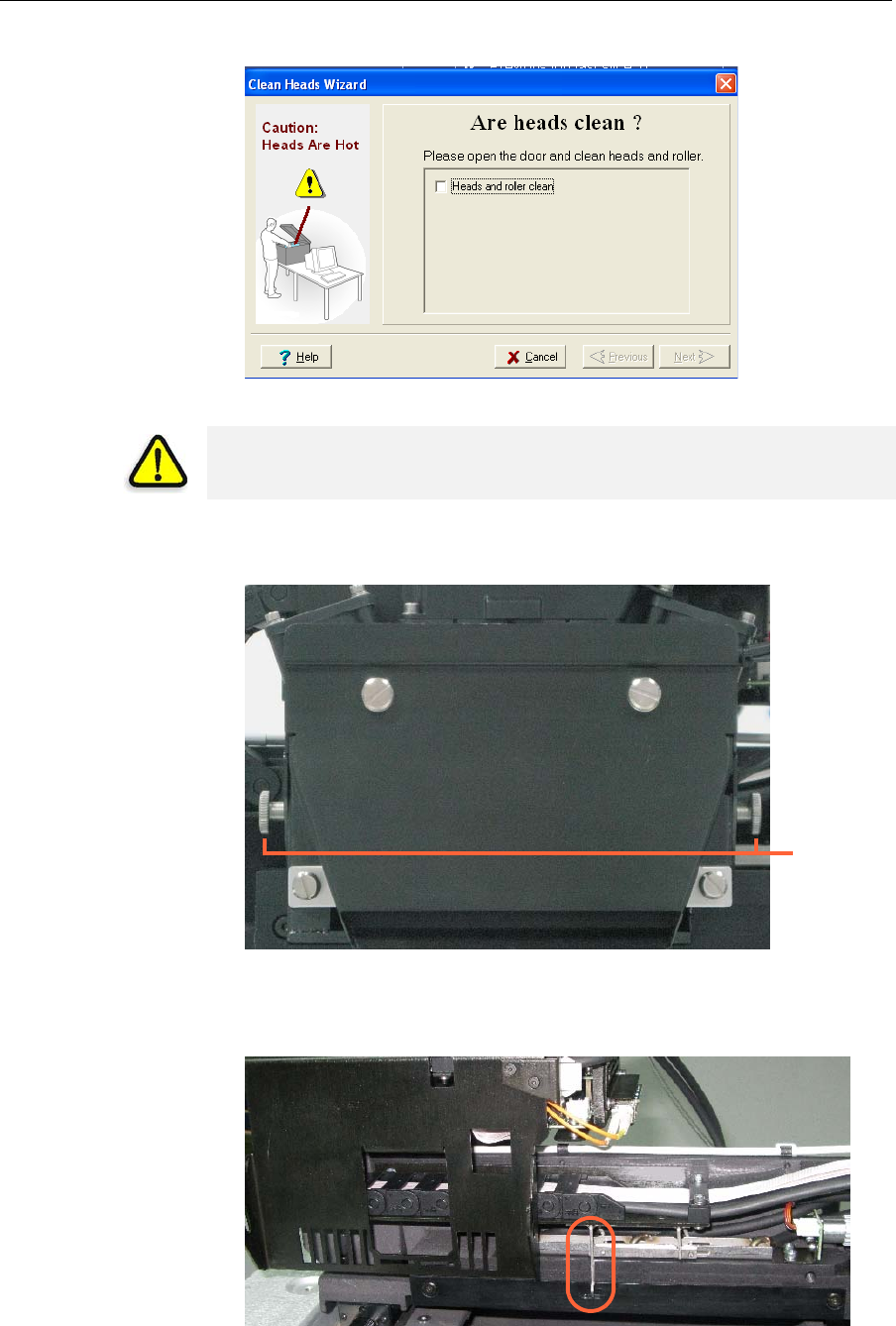
Operating & Maintaining the Alaris30 3-D Printer
7–28
DOC-24000 Rev. A
3. Whenthefollowingscreenappears,openthecover.
Figure 7-39: Wizard screen that appears when you can begin the procedure
4. LoosenthetwosidescrewssecuringtheUVlampassembly,and
removetheassembly.
Figure 7-40: UV-lamp-assembly securing screws
5. Movetheprintblockallthewaytothefrontoftheprinter,exposing
theroller‐waste‐collectorlockingpin.
Figure 7-41: Roller-waste-collector locking pin
WARNING: The print head orifice plates (bottom surface) may be hot.
Do not touch them with your bare hands, and proceed with caution.
Securing
screws
DRAFT 4 - July 11, 2010
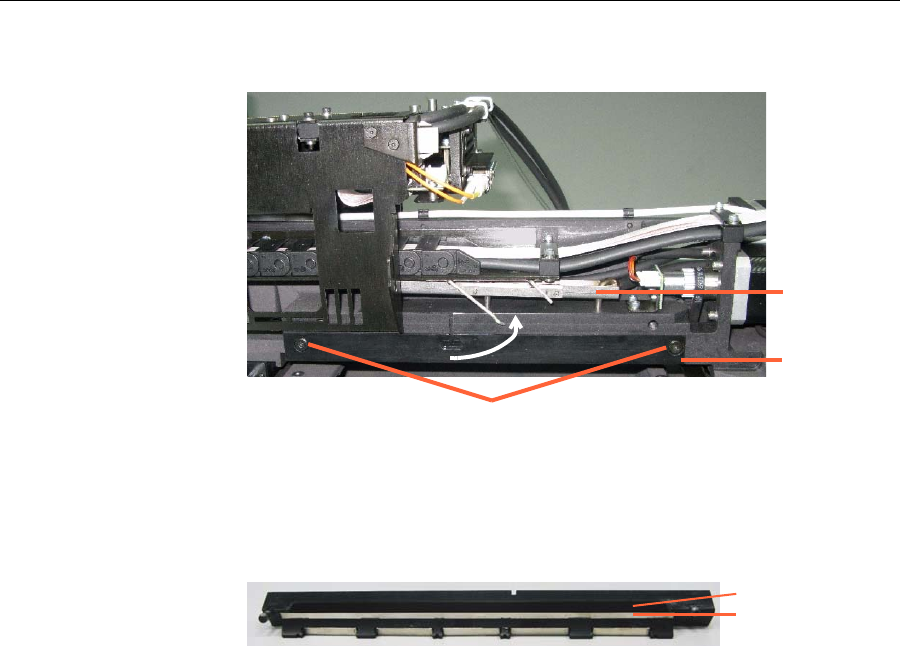
DOC-24000 Rev. A 7–29
Alaris30 User Guide
6. Pullthebottomofthelockingpin,andturnitcounter‐clockwise,to
raisethedrain‐tubebracketfromtherollerwastecollector.
Figure 7-42: Raising the drain-tube bracket
7. Supporttherollerwastecollectorwithyourhandunderit,andusea
3mmAllenkeytoloosenthescrews.
8. Pullouttherollerwastecollector,takingcarenottotouchordamage
thescraper.
Figure 7-43: Roller waste collector
9. Inspecttherollerwastecollector.
•Ifthescraperisdamaged,oraftersixmonthsofuse,replacethe
entireroller‐waste‐collectorunit.
Savetheusedunit.Atthenextmaintenancevisit,thecustomer‐
supportengineerwillreplacethescraper,forfutureuse.
•Ifthescraperisnotdamaged,carefullycleanthewastechannel
withisopropanolandacleaningcloth.
Topreventdamagetothescraper,wipeitfromitsmiddleoutward,
toeachside.
To install the roller waste collector:
1. Carefullyinserttheroller‐waste‐collectorunit.
2. Securetheunitevenly,byalternatelytighteningthescrews.
3. Turnthelockingpinclockwise,tolowerthedrain‐tubebracketonto
therollerwastecollector,andsecurethepininitssocket(see
figure 7‐41onpage 7‐28).
4. Movetheprintblockbacktothemiddleoftheprinter.
5. ReplacetheUVlampassemblyandsecureit.
6. Inthewizardscreen,clickCanceltoreturnthebuildtraytoitsformer
position.
Drain-tube
bracket
Roller waste
collector
Roller-waste-collector screws
Scraper
Waste channel
DRAFT 4 - July 11, 2010
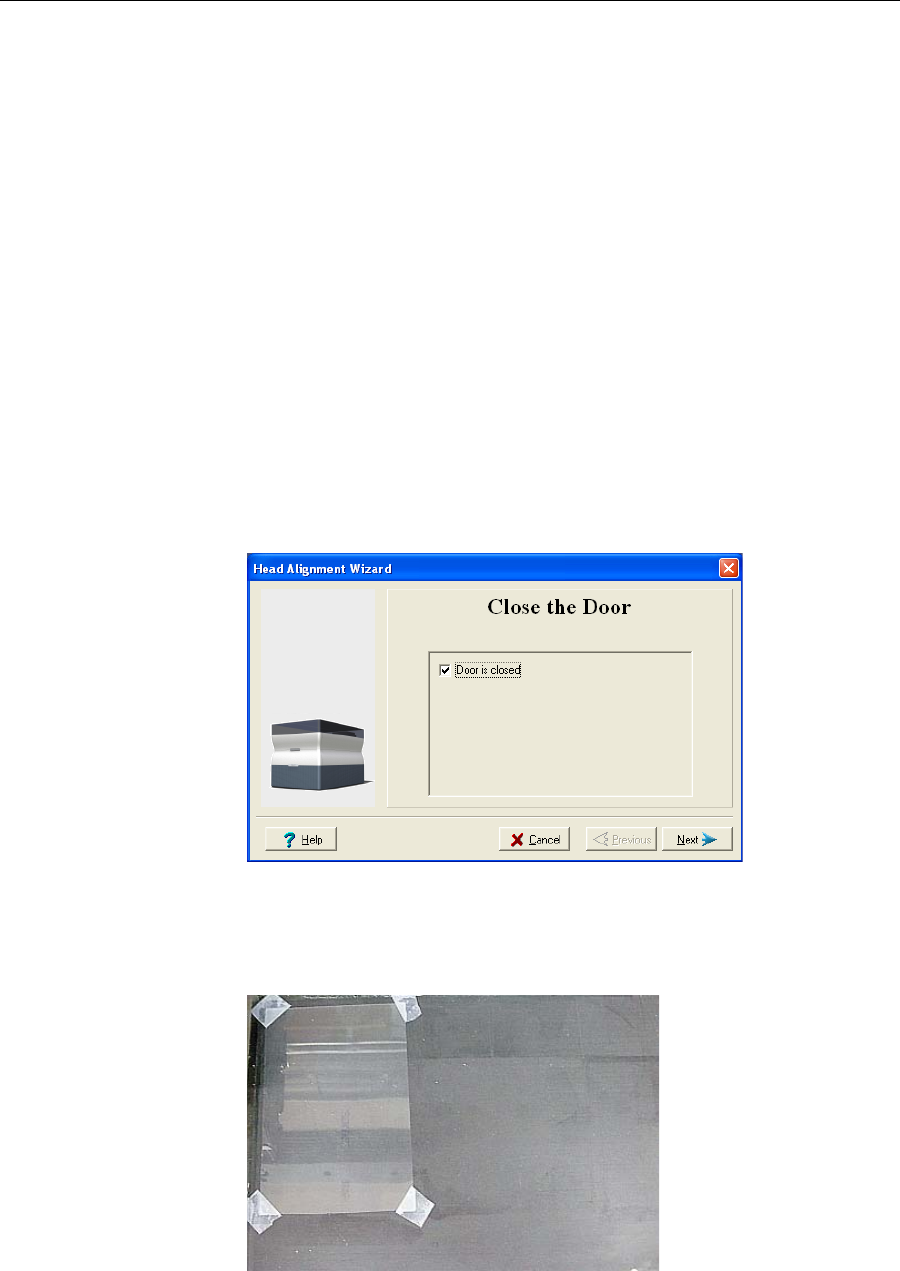
Operating & Maintaining the Alaris30 3-D Printer
7–30
DOC-24000 Rev. A
Aligning the
Print Heads Youshouldcheckthealignmentoftheprintheads—
•onceamonth
•ifmodelqualityisnotacceptableevenaftercleaningtheorificeplateon
thebottomoftheprintblock(see“CleaningthePrintHeads”on
page 7‐21)
Thehead‐alignmentproceduretakesabout20minutes.
To check the alignment of the print heads:
1. Prepare—
•atransparencysheet,atleast10×16centimetersinsize(4.5 ×6.5
inches)—aboutone‐quarterofthestandardA‐4orLettersize
•anytypeofstickytape,tofastenthetransparencysheettothebuild
tray
2. StarttheHeadAlignmentwizard,fromtheAlarisOptionsmenu(see
figure 7‐33onpage 7‐25).
3. ClickNexttobegin,andclosethecover.
4. Inthewizardscreen,selectthecheckboxtoconfirmthatthecoveris
closed,andclickNext.
Figure 7-44: Door is closed confirmation screen
5. Wheninstructedtodoso,placethetransparencyonthebuildtray—
neartheleftandrearedgesofthetray,asshowninthefollowing
figure.
Figure 7-45: Positioning the transparency on the build tray
6. Makesurethatthetransparencysheetislyingflat,andtapeittothe
tray.
DRAFT 4 - July 11, 2010
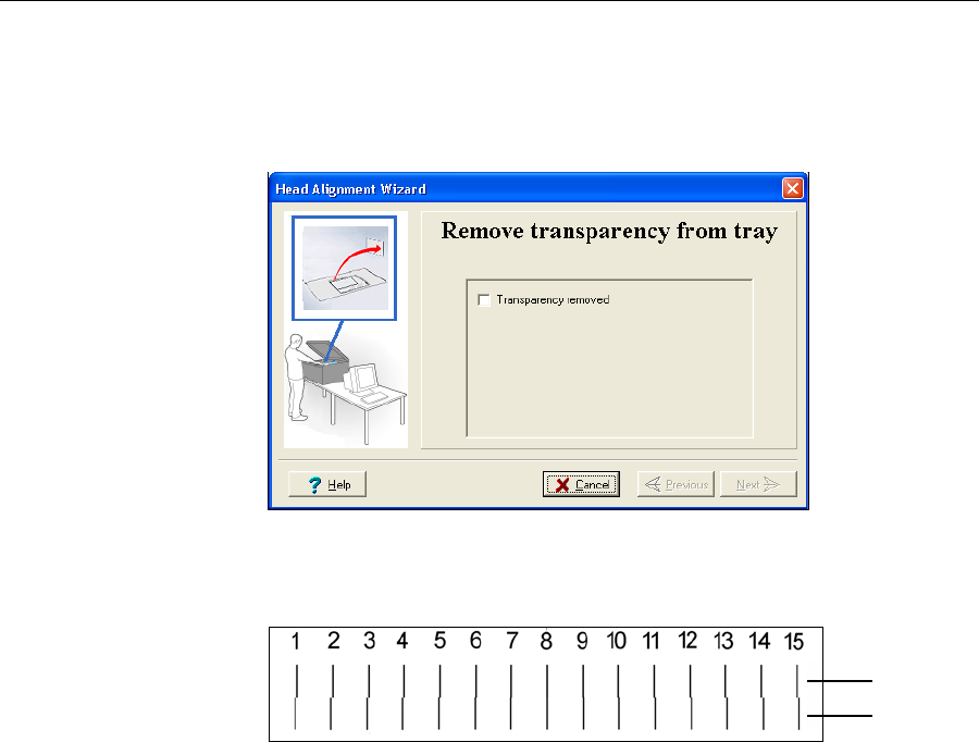
DOC-24000 Rev. A 7–31
Alaris30 User Guide
7. Inthewizardscreen,selectthecheckboxtoconfirmthatthe
transparencysheetisonthebuildtray,andclickNext.
TheAlarisprinterprintstheheadalignmenttestonthetransparency.
8. Whenthefollowingscreenappears,removethetransparency.
Figure 7-46: Head Alignment wizard—steps 8–10
Thetransparencysheetisprintedwithsetsofverticallinesintworows,
eachshowingtheresultsfromadifferentprinthead.
Figure 7-47: Sample head-alignment test
•Thetoprowwasprintedbytheheadusedforapplyingmodel
materialwhenproducingmodels.
•Thebottomrowwasprintedbytheheadusedforapplyingsupport
material.
9. Useamagnifyingglassorloupetoinspectthetransparency.
Optimumheadalignmentisshownwhenthetwo#8lines,intheupper
andlowerrows,arealigned,asinfigure 7‐47.Intheexampleshown,no
changetotheheadalignmentisnecessary.Ifotherlinesinthesetare
aligned,youneedtochangethealignment—inthenextwizardscreen.
10. Inthewizardscreenshowninfigure 7‐46,selecttheTransparency
removedcheckbox,andclickNext.
Model head
Support head
DRAFT 4 - July 11, 2010
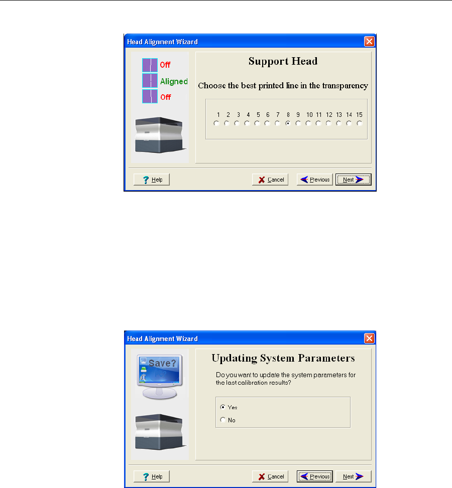
Operating & Maintaining the Alaris30 3-D Printer
7–32
DOC-24000 Rev. A
Thefirstinaseriesofalignmentscreensappears.
Figure 7-48: Head alignment screen
11. Inthehead‐alignmentscreen,selectthenumberthatindicateswhich
linesalignintheupperandlowerrows.
Note: Because the alignment of the middle lines is optimum, the number
“8” is selected, by default, in the wizard screen. This does not change the
head alignment. If you select other numbers, the wizard adjusts the head
alignment, accordingly.
12. ClickNext.
Thefollowingscreenisdisplayed.
Figure 7-49: Updating System Parameters confirmation screen
13. Continueasfollows:
•Tomakethealignmentchangesintheprinter,makesurethatYes is
selected,andclickNext.
•Torecheckthealignmenttestresultsbeforemakingthealignment
changesintheprinter,clickPrevious.
•Ifyoudonotwanttomakealignmentchangesintheprinteratthis
time,selectNoandclickNext.
DRAFT 4 - July 11, 2010
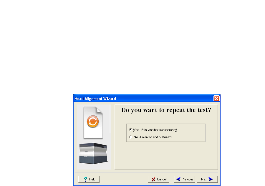
DOC-24000 Rev. A 7–33
Alaris30 User Guide
14. Inthefinalwizardscreen,choosetoeitherrepeattheheadalignment
procedureorclosethewizard.
•Ifthemostcloselyalignedverticallinesforaprintheadwereat
eitherextreme,chooseYes torunthehead‐alignmentwizardagain,
thenclickNext.
Thetransparencytestwillshowiftheheadsarenowproperly
aligned,and—ifnot—thewizardwillallowyouto“finetune”the
alignment.
•Iftheverticallinesfortheprintheadswerenotalignedateither
extreme,chooseNotoclosethewizard,thenclickNext.
Figure 7-50: Final wizard screen
DRAFT 4 - July 11, 2010

Operating & Maintaining the Alaris30 3-D Printer
7–34
DOC-24000 Rev. A
Replacing
Print Heads Theconditionoftheprintheadsdirectlyaffectsthequalityofprinted
models.Youneedtoreplaceaprintheadifoneormoreofthefollowing
symptomsoccurs:
•Therearenoticeablegroovesinthesurfaceofprintedmodels.
•Thepatterntestrevealsthatmorethanfourconsecutivenozzles—ora
totalofmorethan12nozzles—arenotfunctioning.
•Visualinspectionoftheheadrevealsthatitssurfaceisdamaged—
peelingorbubblesinthenozzlearea.
•TheAlarisinterfacedisplaysawarningormalfunctionmessage
relatingtoaprinthead—
HeadHeatertemperaturetimeout
HeadHeaterthermistoropen
HeadHeaterthermistorshort
•Testsrevealthatthematerialprintedbyaprintheadisunderweight
(thatis,notenoughmaterialisbeingoutputted).
Note: Weight tests are performed only by an authorized service engineer.
Awizardguidesyouthroughtheprocedureofreplacingaprinthead,and
adjustscomponentsoftheAlarisprintertoenableyoutoperformit.Only
replaceaprintheadwiththeaidofthewizard.Theproceduretakesabout
75minutes,andconsistsofthefollowingphases:
A. Identifyingthehead(s)needingreplacement.
Thisisusuallydonebyexaminingtheresultsofthepatterntest,after
attemptingallothermeansforimprovingprintquality(see
“ImprovingPrintQuality”onpage 7‐24).Otherwise,evidenceof
physicaldamagetotheheadsurfaceoramalfunctionmessage
indicateswhichheadneedsreplacing.
B. Preparingtheprintblockforheadreplacement.
ThisisdoneautomaticallywhenyouruntheHeadReplacement
wizard.
C. Removingthedefectiveprinthead.
D. Installinganewprinthead.
E. Performingweightcalibration.
Thewizardprintsasample.Afterweighingitonascale,youenterthe
weightinthewizarddialogbox.
F. Performingheadalignment.
Replacing print heads is expensive. Replace them only after attempting all
other means for improving print quality (see “Improving Print Quality” on
page 7-24) and after consulting with an Objet-authorized customer-support
engineer.
DRAFT 4 - July 11, 2010
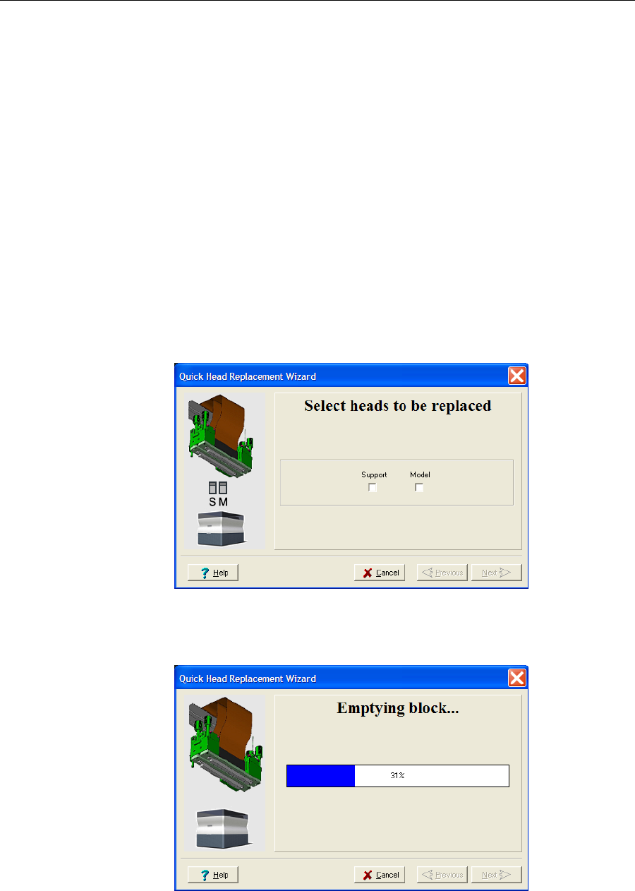
DOC-24000 Rev. A 7–35
Alaris30 User Guide
To replace a print head:
1. Prepare—
•replacementprinthead(s)
•isopropanol(IPA—isopropylalcohol)orethanol(ethylalcohol)
•disposablesafetygloves(includedintheheadreplacementkit)
•anObjet‐suppliedcleaningclothorequivalent
•thescalesuppliedbyObjetforuseintheWeightTest
Note: Make sure that you have these items before running the Head
Replacement wizard.
2. StarttheHeadReplacementwizardfromtheOptionsmenuofthe
printerinterface(seefigure 7‐33onpage 7‐25).
3. Intheopeningwizardscreen,clickNexttobegin.
TheHeadReplacementConditionsscreenappears.
4. Readtheconditions,selectIAgreeandclickNext.
Preparing the
print block 5. Selecttheprinthead(s)needingreplacement,andclickNext.
Figure 7-51: Head selection screen
TheAlarisprinterheatsandemptiestheprintblock,andpreparesthe
printer.(Thisshouldtakeabout10minutes.)
Figure 7-52: Emptying Block progress screen
DRAFT 4 - July 11, 2010
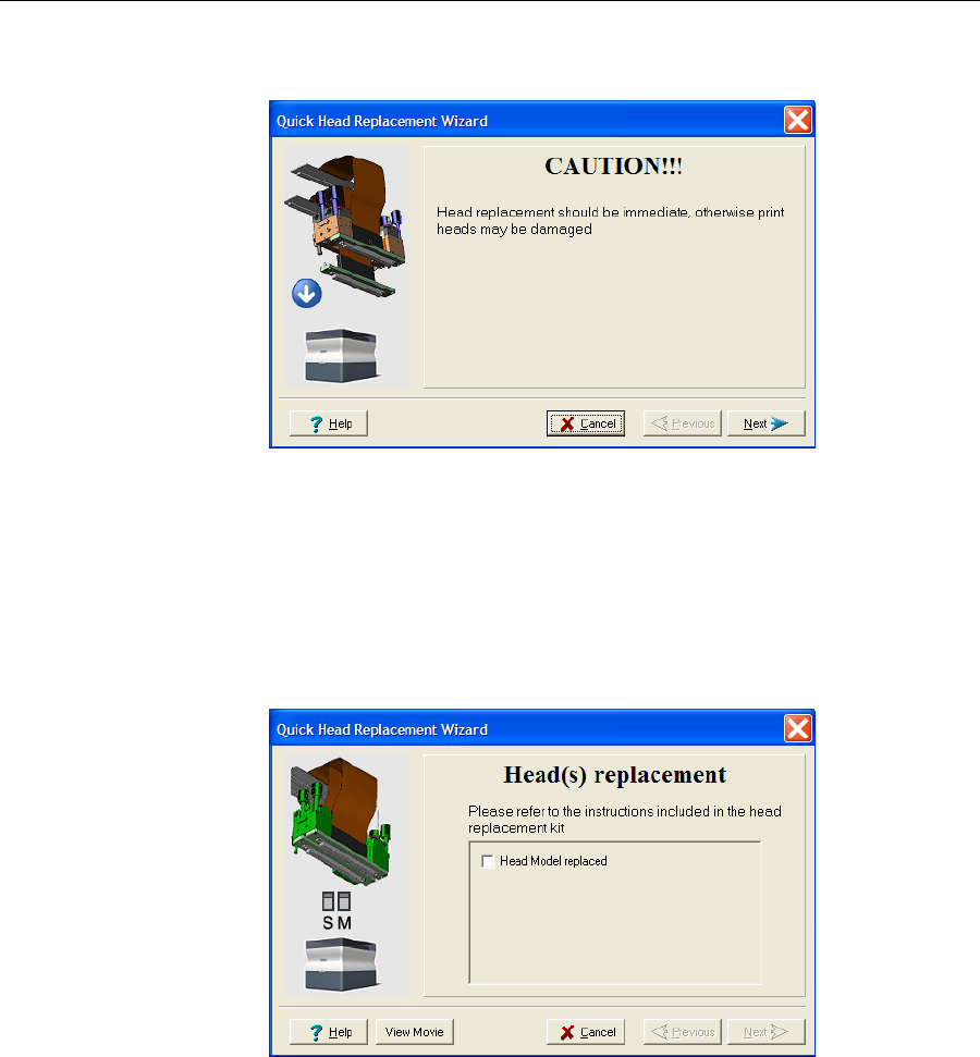
Operating & Maintaining the Alaris30 3-D Printer
7–36
DOC-24000 Rev. A
Whentheprintblockiscompletelydrained,thewizardwipesthe
heads.Then,thefollowingwarningscreenappears.
Figure 7-53: Head Replacement warning screen
6. ClickNextifyouarereadytocontinue.
7. OpentheSingleHeadReplacementkit,andremovethesafetygloves
andtheinstructions.
8. Putonthesafetygloves.
9. Whenthefollowingscreenisdisplayed,opentheAlarisprintercover.
Note: The Alaris printer disconnects power to the heads for your safety.
Figure 7-54: Replace the defective head when this screen appears
DRAFT 4 - July 11, 2010
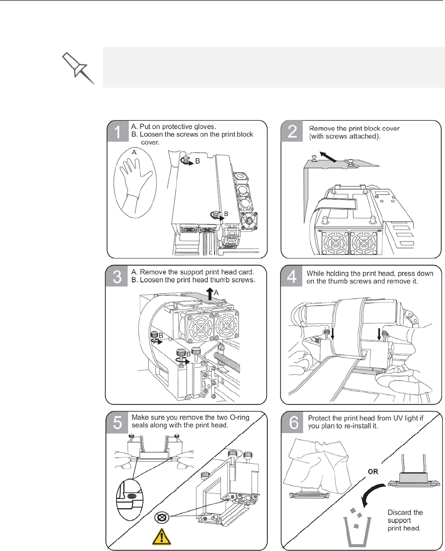
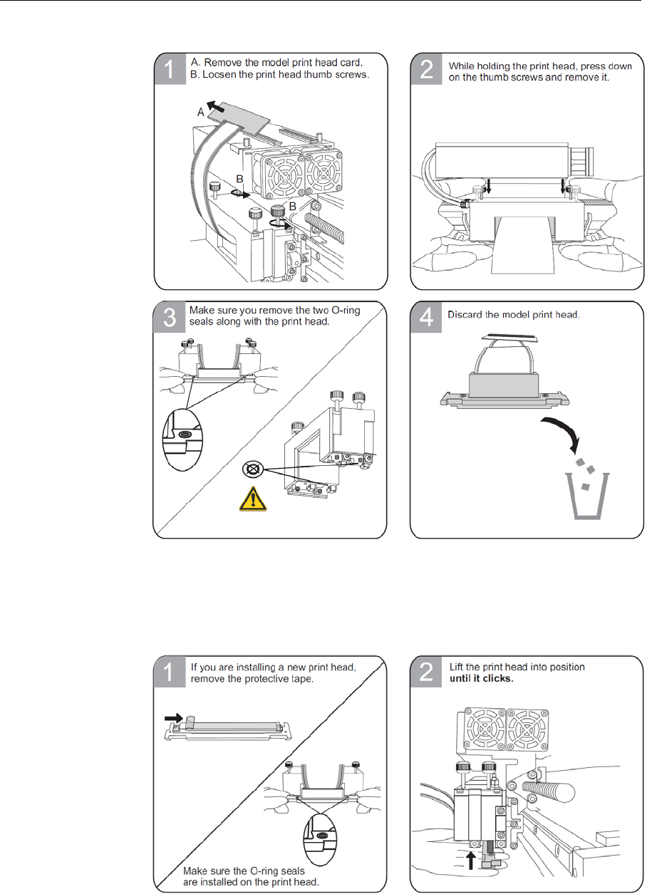
Operating & Maintaining the Alaris30 3-D Printer
7–38
DOC-24000 Rev. A
ModelPrintHead
Installing the
New Head ModelPrintHead
Important:Removetheprotectivetapefromthesurfaceofthe
newprinthead.
DRAFT 4 - July 11, 2010
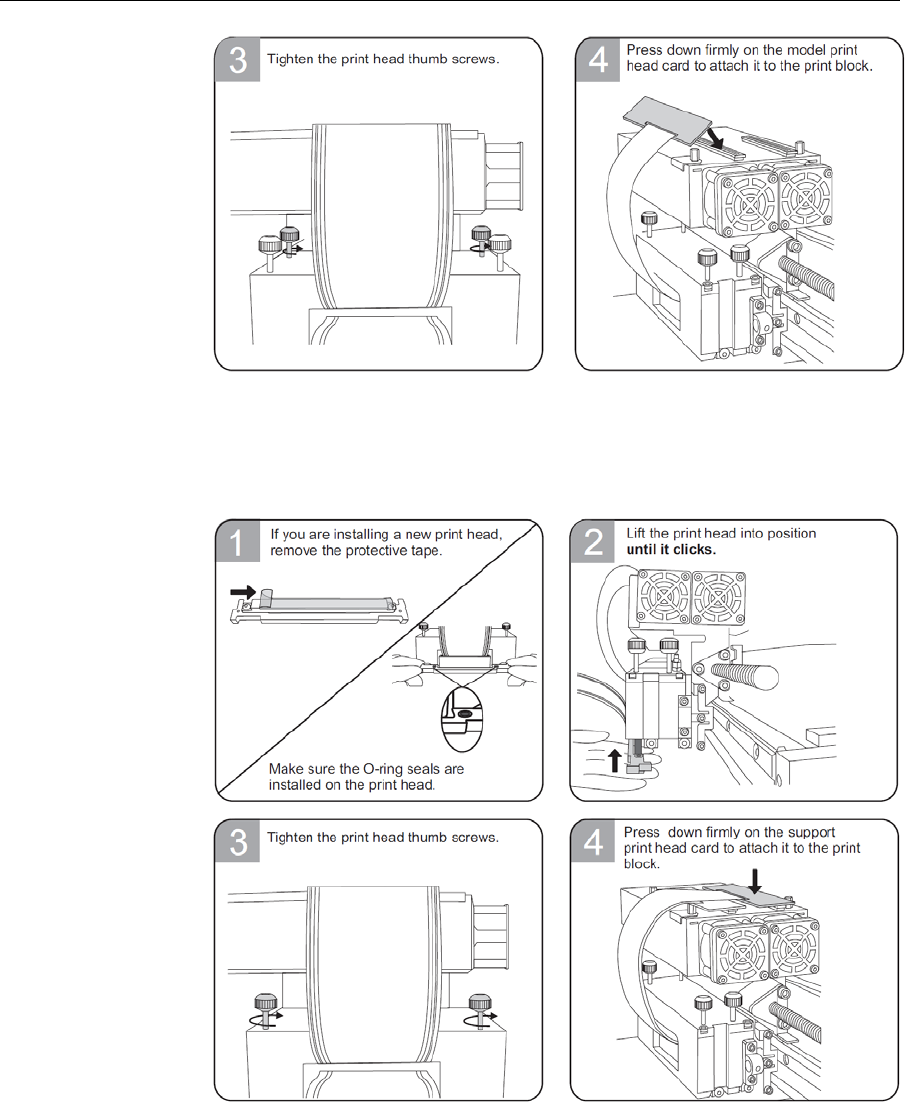
DOC-24000 Rev. A 7–39
Alaris30 User Guide
SupportPrintHead
Important:Removetheprotectivetapefromthesurfaceofthe
newprinthead.
10. IntheHead(s)Replacementscreen(seefigure 7‐54onpage 7‐36),select
thecheckboxtoconfirmthatyouhavereplacedthehead(s),andclick
Next.
DRAFT 4 - July 11, 2010
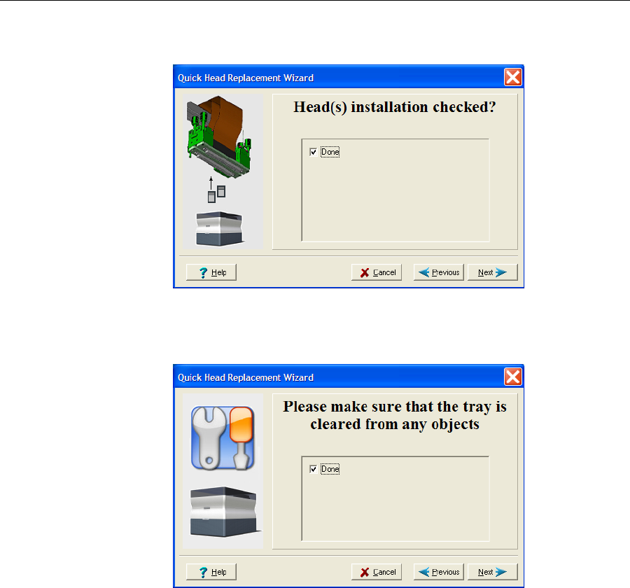
Operating & Maintaining the Alaris30 3-D Printer
7–40
DOC-24000 Rev. A
11. Confirmthattheheadsarelevelandevenbyselectingthecheckboxin
thefollowingwizardscreen,andclickNext.
Figure 7-55: Installation-check screen
12. Inthenextwizardscreen,selectthecheckboxtoconfirmthatyouhave
removedalltoolsandobjectsfromtheprinter.
Figure 7-56: Cleared-tray confirmation screen
13. Closetheprintercover.
Thewizardcontinuesbyfillingtheheads,thenheatingandpurgingthem.
Iftherearenoinstallationproblems,theweightcalibrationprocedure
begins(see“WeightCalibration”onpage 7‐43).
Ifavacuumleakageisdetected,orifthereareotherproblems,thewizard
alertsyouandinstructsyouhowtocontinue(see“InstallationProblems,”
below).
DRAFT 4 - July 11, 2010
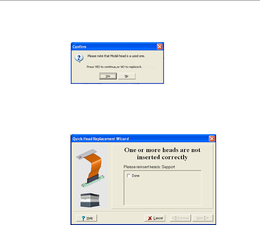
DOC-24000 Rev. A 7–41
Alaris30 User Guide
Installation
Problems
Iftheprinterdetectsthatthereisaproblemafteryouinstallprintheads,
relevantwarningscreensappear.
•Iftheprintheadyouinstalledisnotnew—thatis,itwaspreviously
removedfromaprinter—amessageappears.
Figure 7-57: Used print head message
Tocontinuewiththeinstallationofthisprinthead,clickYes.
Toremovethisprintheadandinstallanewone,clickNo.
•Iftheprintersoftwaredoesnotsensethereplacedhead,thefollowing
warningscreenappears.
Figure 7-58: Incorrect-installation screen, showing which head(s) to re-insert
Ifthishappens:
a. Re‐inserttheprint‐headdrivercardintoitssocket.
b. Inthewizardscreen,selectthecheckboxtoconfirmthatyouhave
re‐insertedthecard,andclickNext.
DRAFT 4 - July 11, 2010
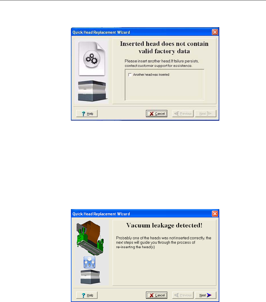
Operating & Maintaining the Alaris30 3-D Printer
7–42
DOC-24000 Rev. A
•Ifthereplacementheadwasnotfactory‐calibrated,thefollowing
warningscreenappears.
Figure 7-59: Invalid-data warning screen
Ifthishappens:
a. Removetheheadandreplaceitwithanotherone.
b. Inthewizardscreen,selectthecheckboxtoconfirmthatyouhave
installedanotherprinthead,andclickNext.
c. ContactyourauthorizedObjetCustomerSupportcenteraboutthe
unformattedhead.
•Ifthevacuumtestisnotsuccessful,thereplacementheadwasnot
sealedproperlyduringinstallation,andthefollowingwarningscreen
appears.
Figure 7-60: Vacuum Leakage warning screen
Ifthishappens:
a. ClickNext.
b. Followtheinstructionsonthewizardscreenstore‐installthehead.
DRAFT 4 - July 11, 2010
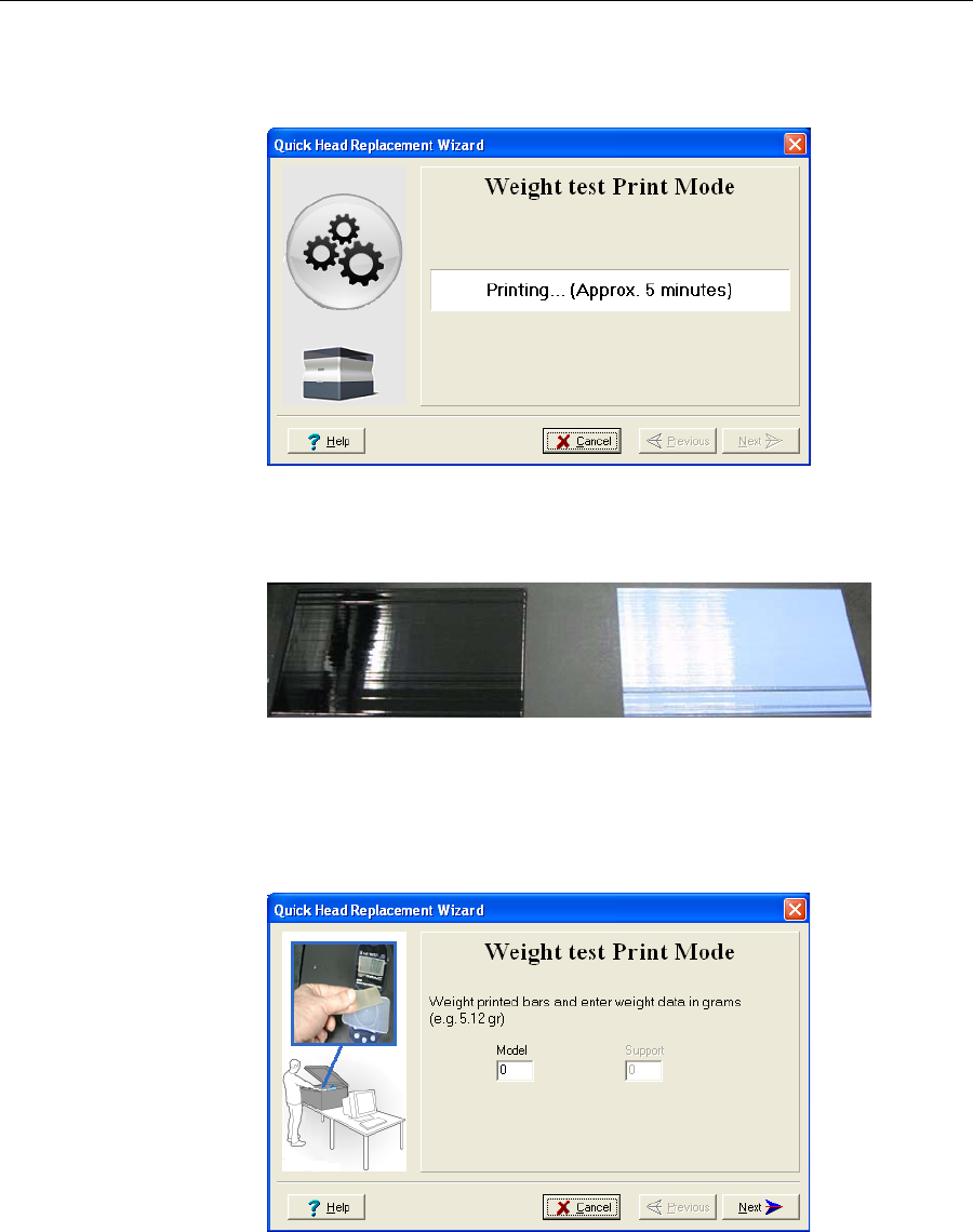
DOC-24000 Rev. A 7–43
Alaris30 User Guide
Weight Calibration Afterthesuccessfulinstallationofprintheads,thewizardbeginsthe
weighttest,inwhicheachheadprintsasample.Thistesttakes15–25
minutes.
Figure 7-61: Weight test progress screen
14. Carefullyremovethesamplesforeachhead,keepingtrackofthehead
thatprintedthem.
Figure 7-62: Samples printed on the Alaris printer build tray
15. Usingthescale,weigheachsampleandentertheweight(ingrams)for
thecorrespondingheadinthewizardscreen.
16. Closetheprintercover,thenclickNext.
Figure 7-63: Weight Test data entry screen
Support Print Head Model Print Head
DRAFT 4 - July 11, 2010
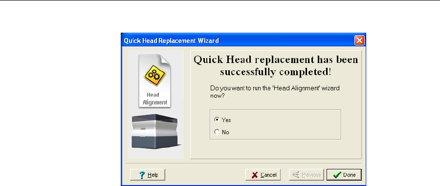
Operating & Maintaining the Alaris30 3-D Printer
7–44
DOC-24000 Rev. A
AftertheAlarisprintercalibratesitself,thelastwizardscreenappears.
Figure 7-64: Final Head Replacement screen
17. Afterreplacingprintheads,youshouldchecktheheadalignment
beforeusingtheAlarisprintertoproducemodels.
•SelectYesandclickDonetoopentheHeadAlignmentwizard(see
“AligningthePrintHeads”onpage 30).
•SelectNoandclickDonetoaligntheheadsatanothertime.
18. Inthefinalwizardscreen,clickDone.
DRAFT 4 - July 11, 2010
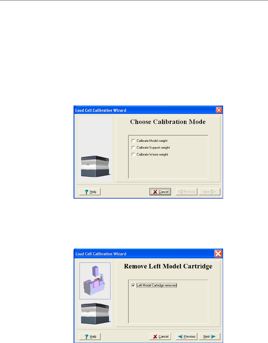
DOC-24000 Rev. A 7–45
Alaris30 User Guide
Calibrating the
Load Cells Loadcellsaresensorsthatmeasuretheweightoftheprintingcartridges
andthewastecontainerintheprinter.Itisimportantthatyouperiodically
checkthattheweightmeasurementsareaccurate,bothforconvenienceand
topreventunnecessarywasteofprintingmaterials.Itisrecommendedthat
youcalibratetheloadcellsonceamonth,withtheLoadCellCalibration
wizard.
To calibrate load cells:
1. StarttheLoadCellCalibrationwizard.
•FromtheOptionsmenuoftheprinterinterface(seefigure 7‐33on
page 7‐25),selectWizards > Load Cell Calibration.
2. Selectoneormoreloadcellsthatyouwanttocalibrate,andclickNext.
Figure 7-65: Load cell selection
Note: It is recommended that you routinely calibrate all of the load cells,
after 500 hours of printing or once every six months.
3. Removethecartridgeorcontainer,asinstructedbythewizard,
confirmthisinthewizardscreen,andclickNext.
Figure 7-66: Confirmation of cartridge removal
DRAFT 4 - July 11, 2010
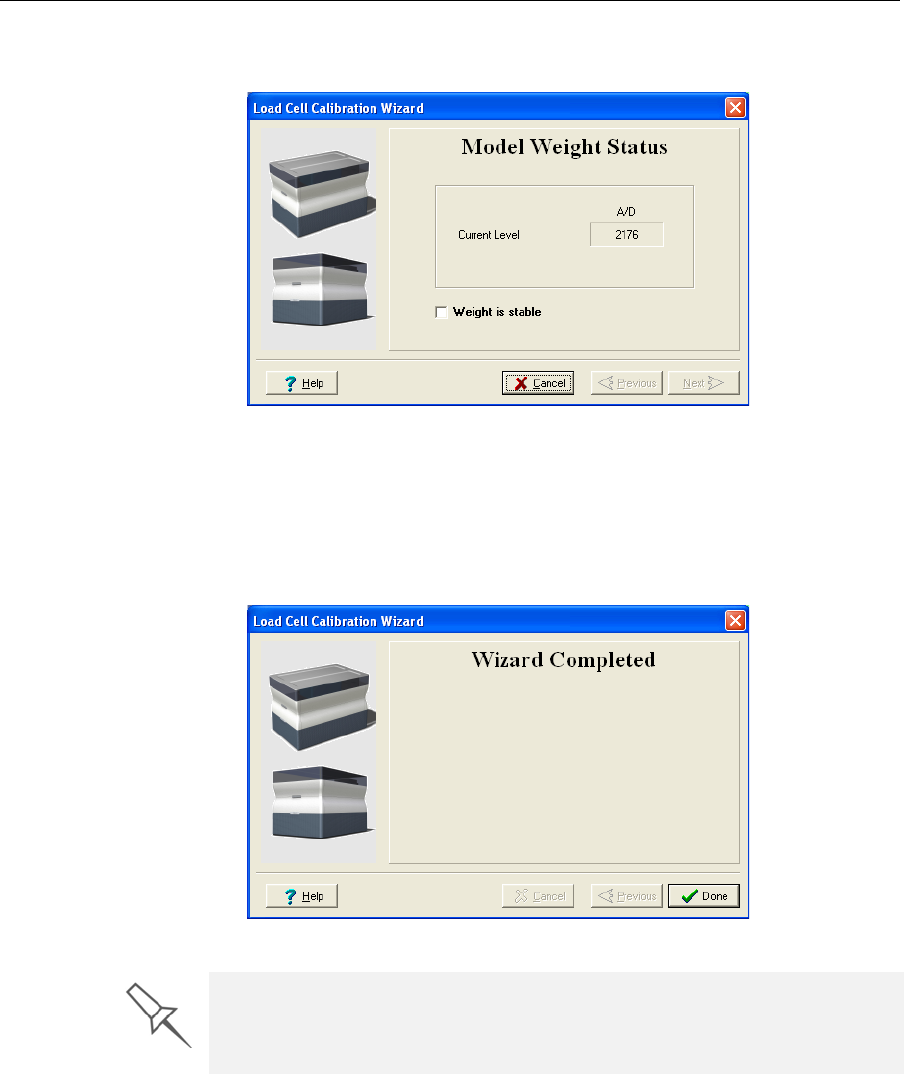
Operating & Maintaining the Alaris30 3-D Printer
7–46
DOC-24000 Rev. A
4. Inthenextwizardscreen,observethenumbersandwaituntilthelevel
isrelativelystable—twounitsaboveorbelowtheaveragelevelshown.
Figure 7-67: Load cell calibration screen
5. SelecttheWeightisstablecheckbox,andclickNext.
Ifyouneedtocalibratemorethanoneloadcell,thenextcalibration
screenappears.Repeatsteps4and5untilalloftheloadcellsare
calibrated.
6. ClickDoneinthefinalwizardscreen.
Figure 7-68: Final wizard screen
If you removed the waste container, make sure to replace it with its metal
cover, and make sure that the drain tube is not bent. Operating the printer
without the waste-container cover results in an inaccurate measurement of
the waste weight, which will cause waste to overflow into the printer.
DRAFT 4 - July 11, 2010
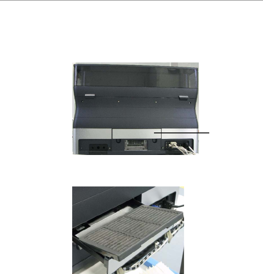
DOC-24000 Rev. A 7–47
Alaris30 User Guide
Replacing the
Odor Filter TheAlaris30printerhasanactivated‐carbonfilterforremovingodorsfrom
printingmaterials.Thefiltershouldbereplacedregularly(aboutoncea
year,asnecessary)tokeepyourworkingenvironmentpleasant.Thisis
normallydoneduringtheyearlypreventive‐maintenanceservicevisit.
To replace the odor filter:
1. Locatethefilterdrawerattherearoftheprinterandpullitopen.
Figure 7-69: Rear of the Alaris30 printer
2. Removetheusedfilter.(Youcanpushitoutfromunderneaththe
drawer.)
Figure 7-70: Odor filter in drawer
3. Insertanewfilterandclosethedrawer.
Odor filter drawer
DRAFT 4 - July 11, 2010
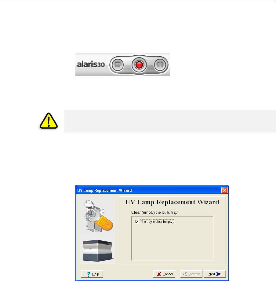
Operating & Maintaining the Alaris30 3-D Printer
7–48
DOC-24000 Rev. A
Replacing the
UV Lamp TheUVlampusedforcuringmodelshasalong,butlimited,workinglife.
TheObjetserviceengineertestsitseffectivenessduringregular
maintenancechecks,andreplacesit,ifnecessary.If,foranyreason,you
needtoreplacetheUVlamp,followtheseinstructions:
1. MakesuretheAlarisprinterisinofflinemode.
Figure 7-71: Offline mode indicator (red)
Theonline/offlinebuttontheprinterinterfaceshouldbered.Ifnot,click
ittoswitchtheprintertoofflinemode.
2. StarttheUVLampReplacementwizard.
FromtheOptionsmenuoftheprinterinterface(seefigure 7‐33on
page 7‐25),selectWizards > UV Lamp Replacement.
3. Makesurethatthebuildtrayisempty,andconfirmthisinthewizard
screen.Then,closetheprintercoverandclickNext.
Figure 7-72: “Empty tray” confirmation screen
Theaxesmovetothe“home”position.
WARNING: Before continuing, make sure that the safety interlock in the
printer cover is not defeated, and that the lamp is not hot.
DRAFT 4 - July 11, 2010
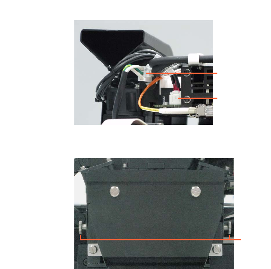
DOC-24000 Rev. A 7–49
Alaris30 User Guide
4. DisconnecttheUVlampcableandthefancable.
Figure 7-73: Disconnecting the UV lamp assembly
5. LoosenthetwosidescrewssecuringtheUVlampassemblytothe
printer.
Figure 7-74: UV-lamp-assembly
6. Removetheassembly,andplaceitonaflatsurface.
UV-lamp connector
UV-fan connector
Securing
screws
DRAFT 4 - July 11, 2010
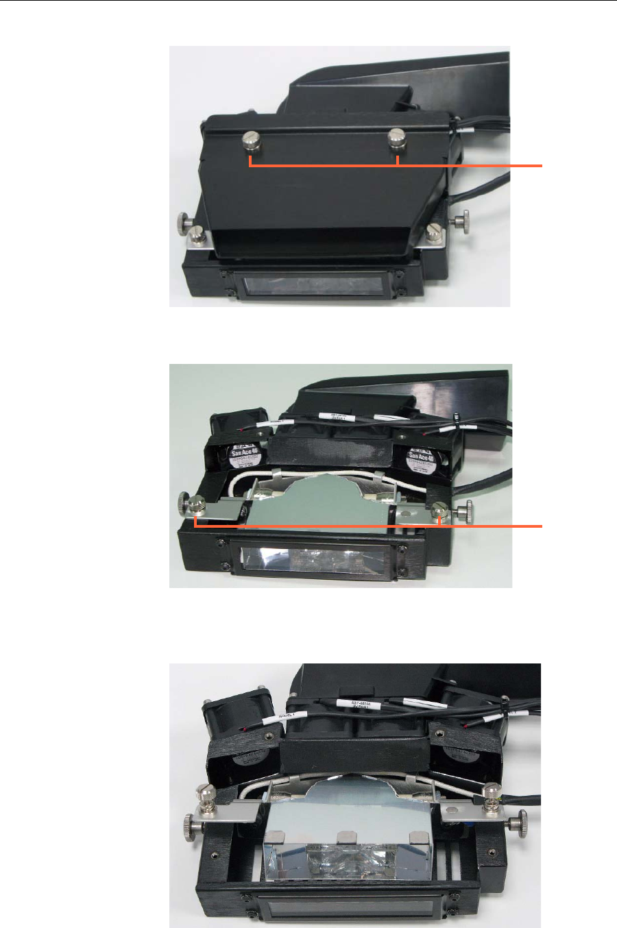
Operating & Maintaining the Alaris30 3-D Printer
7–50
DOC-24000 Rev. A
7. LoosenthescrewssecuringtheUVlampcoverandremovethecover.
Figure 7-75: UV-lamp-cover screws
8. LoosenthetwoscrewssecuringtheUVreflector.
Figure 7‐76:UV‐reflectorscrews
9. RemovetheUVreflectorbyraisingitslightly,thenpullingitoutofthe
housingatanangle,fromthebottom.
Figure 7-77: Removing the UV reflector from the UV assembly
Cover screws
Reflector
screws
DRAFT 4 - July 11, 2010
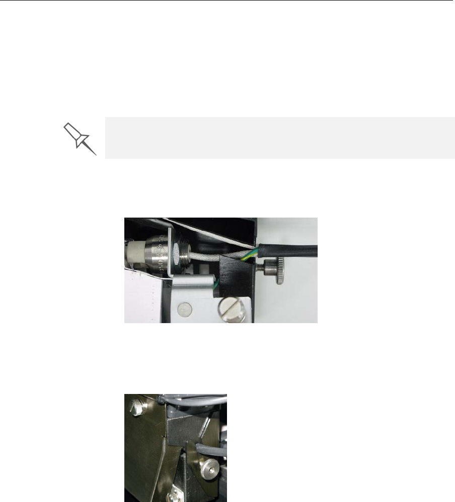
DOC-24000 Rev. A 7–51
Alaris30 User Guide
10. Inspectthenewlampreflector,andmakesurethatablackstripis
attachedtotheinsideofit.Ifnot,installone—onthesideofthe
reflectoropposite(notnextto)theprintblock.
Note: Extra black strips are included in the printer Start-up Kit. If
necessary, you can remove the black strip from the old reflector and install
it in the new reflector (as long as the black paint has not faded).
11. Discardtheoldreflectorandlamp.
12. InsertthenewUVlamp/reflectorunitintothehousing.
13. MakesurethattheUV‐lampcableisinplace,insidethehousing,and
thentightenthesecuringscrews.
Figure 7-78: Cable position when installing the UV lamp
14. Replacethelampcover,andtightenthesecuringscrews.
15. ReplacetheUVlampassemblyintheprinter,makingsurethatthe
cablefitsintotheslottogetherwiththesidesecuringscrew.
Figure 7-79: UV-lamp cable after replacing the assembly
16. Tightenthetwosidesecuringscrews.
17. Reconnectthepowerconnections(seefigure 7‐73).
Dispose of the used UV lamp in accordance with environmental and safety
requirements.
DRAFT 4 - July 11, 2010
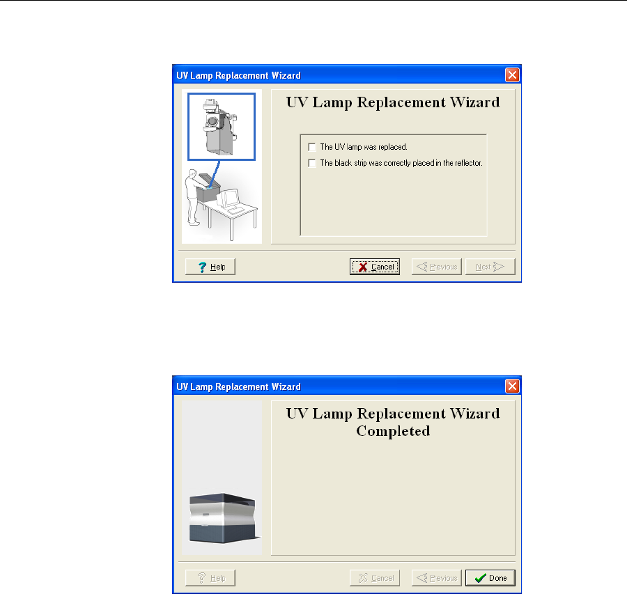
Operating & Maintaining the Alaris30 3-D Printer
7–52
DOC-24000 Rev. A
18. Inthewizardscreen,confirmthatyouhavereplacedthelampandthat
theblackstripisattached,thenclickNext.
Figure 7-80: Installation confirmation screen
Thewizardoperatesthelamptotestifitisinstalledcorrectly.Ifthe
lampdoesnotlight,thewizardpromptsyoutocheckthepower
connectionsandtore‐installthelamp.
Figure 7-81: Final wizard screen
DRAFT 4 - July 11, 2010
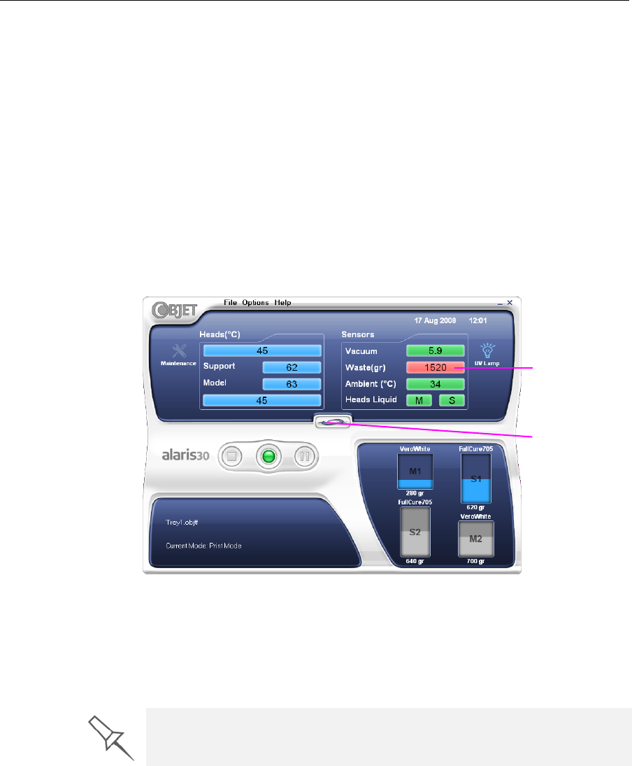
DOC-24000 Rev. A 7–53
Alaris30 User Guide
Replacing the
Waste
Container
Thewastecontainercontainspartiallycuredpolymericmaterialproduced
duringnormaloperationandmaintenanceoftheAlarisprinter.Forsafety
andenvironmentalreasons,thismaterialiskeptinaspecialleak‐proof,
disposablecontainer.
Thecontainerhasacapacityoftwokilogramsofwastematerial—usually
enoughforseveralweeksofprinteruse.Theprintersoftwaredisplaysa
warningmessagewhenthecontainerweighs1.3kilograms,andstopsthe
printerwhenitweighs2.0kilograms.Above1.8kilograms,thesoftware
doesnotallowyoutostartaprintjobuntilyoureplacethewastecontainer.
YoucanmonitortheweightofthewastecontainerintheMaintenance
screenoftheprinterinterface.
To monitor the waste weight (and other indicators) in the Alaris printer:
¾Inthemainprinterinterfacescreen,clickthedisplaytoggletoviewthe
Alarisprinterindicators.
Figure 7-82: Alaris printer interface, showing waste weight (red background
indicates operator alert)
Thewastecontainerconsistsofasealedbaginsideacardboardbox.You
typicallydisposeoftheentirewastecontainer—includingthebox.
Therefore,youmustassembleanewboxandinsertanewwastebagbefore
youcaninstallitintheprinter.
To prepare a new waste container:
1. Assemblethecardboardbox,makingsuretopunchouttheperforated
sections.
2. Foldanewwastebag—soitfitsinthebox—andinsertthebag’sscrew‐
connectorintotheholeinthetopofthebox.
Note: Do not close the box until you connect the waste drain tube from the
printer (see below).
Display
toggle button
Waste weight
Replacement boxes, waste bags, and sealing caps are supplied in the
Alaris printer start-up kit and in the preventive-maintenance kit.
DRAFT 4 - July 11, 2010
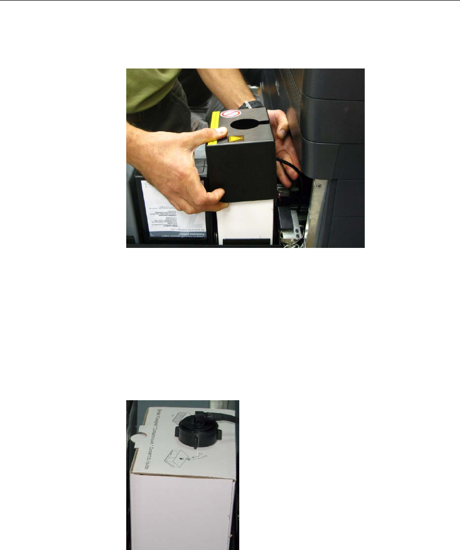
Operating & Maintaining the Alaris30 3-D Printer
7–54
DOC-24000 Rev. A
To replace the waste container:
1. Openthematerialsdrawer.
2. Removethefireproofcoverfromthewastecontainer.
Figure 7-83: Removing the waste-container cover
3. Unscrewthecapsecuringthewastedraintube.
4. Carefullyliftoutthewastecontainertoremoveitfromtheprinter.
5. Closethefullcontainerwithasealingcap.
6. Placethenewwastecontainerinthematerialsdrawer,andattachthe
draintubetoit.
Whileattachingthecapwiththewastedraintube,holdthewastebag
stationary.
7. Closethenewwaste‐containerbox.
Figure 7-84: Waste container with drain tube attached
DRAFT 4 - July 11, 2010
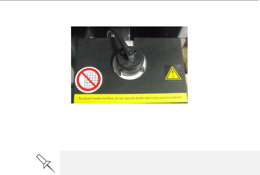
DOC-24000 Rev. A 7–55
Alaris30 User Guide
8. Placethefireproofcoveroverthewastecontainer,makingsurethatthe
draintubeisfreeandnotbent.
Figure 7-85: Fireproof cover installed over the waste container
Note: Operating the printer without the waste-container cover results in an
inaccurate measurement of the waste weight, which will cause waste to
overflow into the printer.
9. Closethematerialsdrawer.
Cleaning the
Exterior Panels ThepaintedexteriorplasticpanelsofAlaris3‐Dprintershaveadurable
finish,offeringexcellentchemicalresistancetocommoncleaningagents.
However,followtherecommendationsbelowwhencleaningtheseareasof
theprinter.
AcceptableCleaningAgents
•mildsoapsolution
•commonhouseholdcleanersandwindowcleaners
•commoncommercialandindustrialdetergents,5%solutioninwater
•alcohol(ethanol,isopropanol),10%to40%solutioninwater
Wipetheexterioroftheprinter,usingasoftclothmoistenedwiththe
cleaningsolution.
UnacceptableMaterials
•industrialsolvents
•cleaningagentscontaininghydrocarbons,ketones,estersandlacquer
thinners
•spraydisinfectants
•abrasivesandagentswhichcouldwearawaythepanelfinish
Dispose of the full waste container in accordance with environmental and
safety requirements.
DRAFT 4 - July 11, 2010

Operating & Maintaining the Alaris30 3-D Printer
7–56
DOC-24000 Rev. A
Backing-Up
and Restoring
Printer
Settings
Printermodesandconfigurationsettingsarestoredinfilesontheprinter
computer.Youcanbackupthesefiles,andrestorethem,ifnecessary,using
desktopicons.
Figure 7-86: Backup and restore desktop icons
ReInitiate
Wizard OneofthewizardslistedintheOptionsmenuisReInitiate.Younormallydo
nothavetorunthiswizard.Theprocessthatthiswizardcontrolsruns
automatically,whenneeded,aspartofthePre‐printmode(beforeprinting
begins).RunthiswizardonlyifanObjetCustomerSupportengineer
instructsyoutodoso.
DRAFT 4 - July 11, 2010

DOC-24000 Rev. A 8–1
Handling Printed Models
RemovingModelsAfterPrinting...................................................... 2
RemovingtheSupportMaterial........................................................ 2
StoringModels..................................................................................... 3
DRAFT 4 - July 11, 2010

Handling Printed Models
8–2
DOC-24000 Rev. A
Removing Models After Printing
Afterprintingmodels,youshouldallowthemtocoolasmuchaspossible
beforehandlingthem.Ifadditionalmodelsdonothavetobeproducedon
theAlarisprinter,itisbesttolettheprintedmodelscoolintheprinter,with
thecoverclosed,aslongaspossible.
If the Alaris printer must be used to produce additional models as soon
as possible:
1. Lettheprintedmodelscoolonthebuildtrayforatleast10minutes.
2. Verycarefully,removethemodelsfromthetraywithascraperor
spatula(suppliedinthetoolkit),takingcarenottopryorbendthe
model.
3. Placethemodelsonaflatsurface,andcoverthemwithacardboard
boxorpaperhood.
Thisallowsthemodelstocoolslowlyandevenly.
4. Letthemodelscoolforseveralhours.
Removing the Support Material
Afterprintedmodelshavecooled,thesupportmaterialmustberemoved.
Thiscanbedonebydifferentmethods,dependingonthesizeofthemodel,
howdelicateitis,theamountandlocationofthesupportmaterial,and
otherfactors.Usethefollowingmethodsasaguide,andadaptthem(ora
combinationofthem)forfinishingthemodelsyouarehandling.
Removing Excess Support Material by Hand
Whilewearingprotectivegloves,breakawayexcesssupportmaterialon
theoutsideofthemodel.Fordelicatemodels,useatoothpick,pinorsmall
brushafterdippingthemodelinwater.
Removing Support Material with Water Pressure
Formostmodels,themostefficientwaytoremovesupportmaterialisby
usingahigh‐pressurewaterjet.OnesuitablesystemistheObjetWaterJet
cleaningunit,showninfigure 8‐1onpage 8‐3.
WARNING: Wear protective gloves when handling printed models
before they are washed.
DRAFT 4 - July 11, 2010
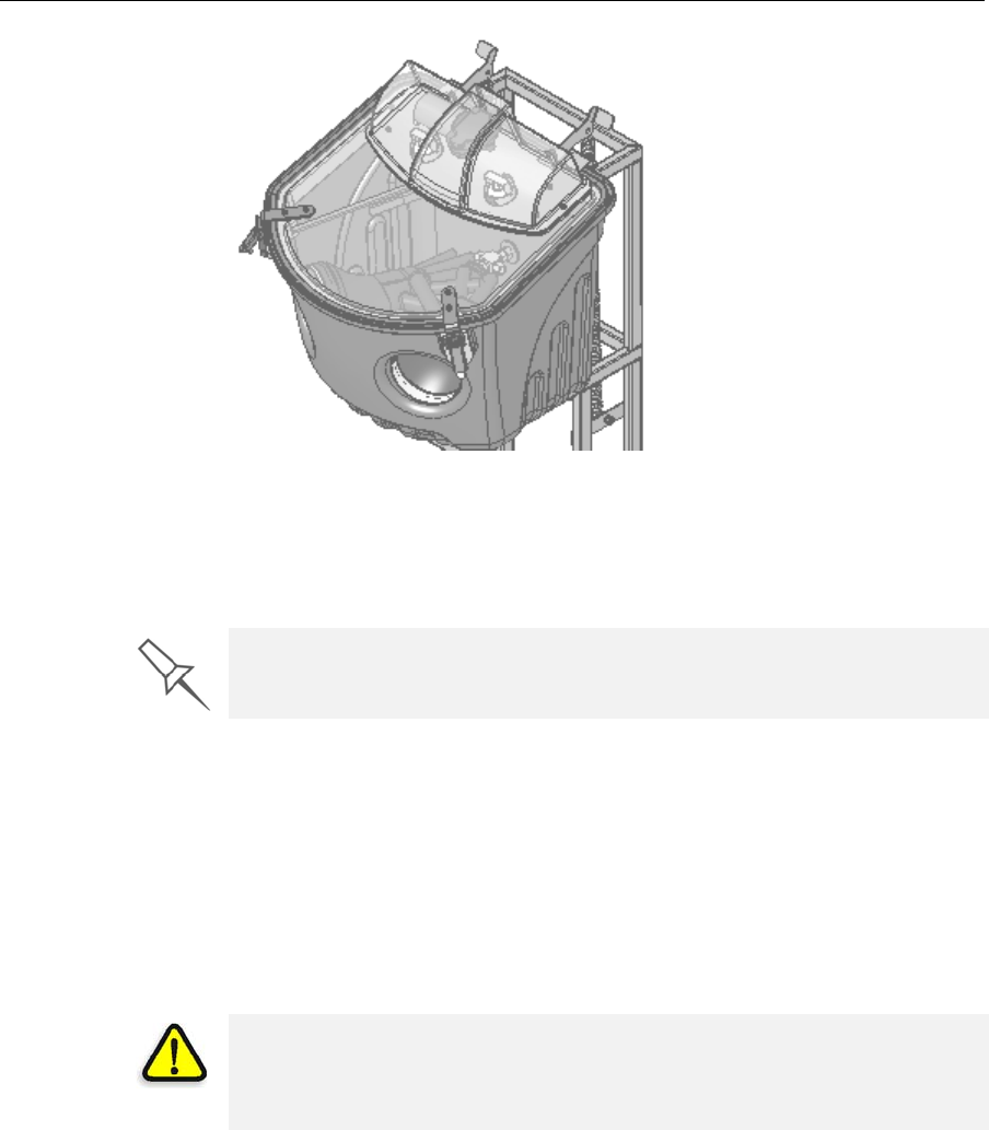
DOC-24000 Rev. A 8–3
Alaris30 User Guide
Figure 8-1: Objet WaterJet Cleaning Unit
Tocleanamodelusingthisdevice,youplaceitinthechamber,andyou
manipulateitandthejetusingthebuilt‐in,waterproofsleeves.Apump
turnsordinarytapwaterintoahigh‐pressurejet,andawiperkeepsthe
windowclear.
Removing Support Material with Caustic Soda
Soakmodelsina2‐percentsolutionofcausticsoda(sodiumhydroxide)to
removesupportmaterialfromdifficult‐to‐reachareasandtogivethe
modelasmooth,cleanfinish.Theamountoftimeyousoakthemodelinthe
solutiondependsonhowdelicateitisandhowmuchsupportmaterial
needstoberemoved,butitistypicallybetweenhalf‐an‐hourandseveral
hours.Inanycase,youshouldremoveasmuchsupportmaterialas
possiblebeforethecausticsodatreatment,andrinsethemodelthoroughly
(withawaterjet)afterwards.
Storing Models
Modelsarecuredastheyareprinted,makingthemsafeandstablefora
longtime.However,properstorageconditionsarenecessarytoprevent
deforming.
•Keepprintedmodelsatroomtemperatureandinalow‐humidity
environment.
•Donotexposemodelstodirectsunlightandotherheatsources.
Use caution when cleaning delicate models with high-pressure water
systems.
WARNING: Caustic soda may cause chemical burns, scarring and
blindness. Mixing it with water generates heat that could ignite other
materials.Take adequate safety precautions; always use nitrile gloves
when handling caustic soda and models soaked in it.
DRAFT 4 - July 11, 2010

Handling Printed Models
8–4
DOC-24000 Rev. A
DRAFT 4 - July 11, 2010