Sun Communications DECT64-S96-B11 US DECT PHONE- BASE User Manual SunCorp Generic GAP Specification
SunCorp Communications Limited US DECT PHONE- BASE SunCorp Generic GAP Specification
UserManual.wiki
>
Sun Communications
>
DECT64 S96 B11 User Manual
USERS MANUAL
Navigation menu
Upload a User Manual
Namespaces
Wiki Guide
HTML
PDF
Info
Views
User Manual
Discussion / Help
Navigation

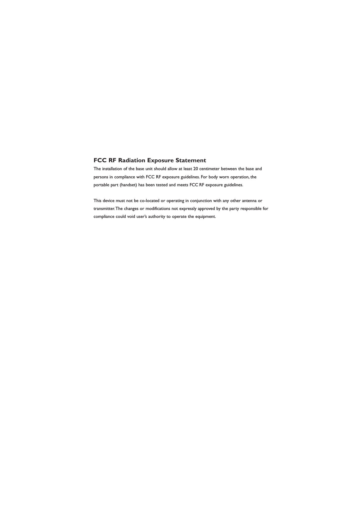

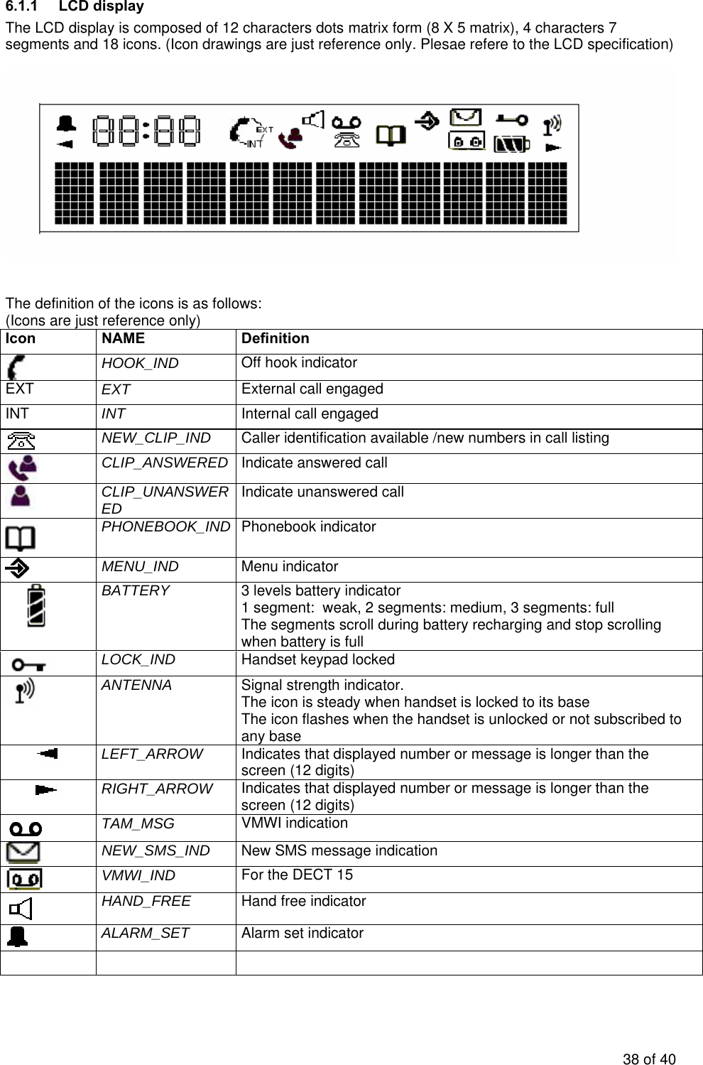
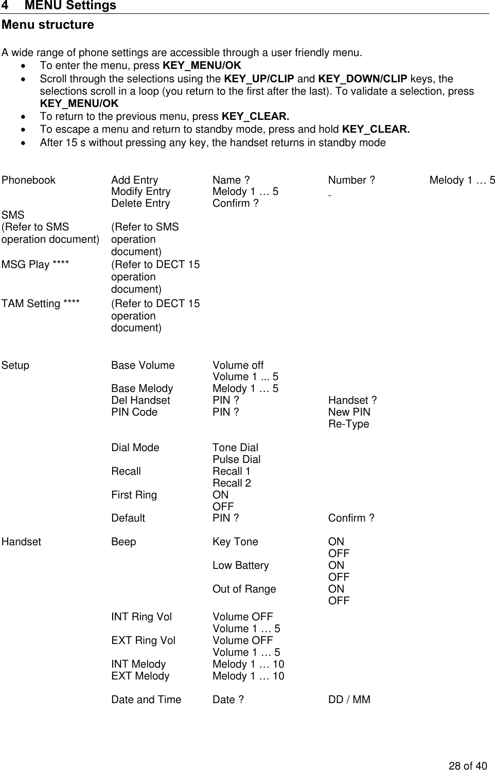
![Up to 20 last redial numbers (32 digits) are stored in the redial list (in PP EEPROM). Outgoing calls to SMS service centre will not be stored in the call list. The last calls appear with their name if they are stored in the phonebook. To retrieve the entries: Press KEY_LNR If the list is already empty, then “empty” is displayed on the 1st line. • When view the redial list, the 1st line to display most update data and 2nd line to display next list. • Press KEY_DOWN/CLIP to move the 2nd line data to 1st line and 2nd line to display next data. Press KEY_UP to move the 1st line data to 2nd line and 1st line to display most old redial data. • There is arrow icon on the left side of the 1st line to indicate that • Scroll through the calls with the up KEY_UP/CLIP and down KEY_DOWN/CLIP arrows. The phonebook name is displayed if it exists. Otherwise it displays the first 11 digits of the number. If the digits are more 11, the first 11 digits of number are displayed with icon. Press KEY_OK to check the remaining digits with icon. • Press KEY_OK to toggle between name and number if the number is matched with phonebook entry. (This is only for 1st line data) • Press KEY_MEM/EXIT return to standby mode To dial out number just simple press KEY_HOOK. [Display example] (Arrow icon is always on the 1st line left side) 3.4.3 Dial out redial after OFF HOOK To recall the last redial entry, just take the line by KEY_HOOK and press KEY_LNR to dial. 3.4.4 Delete a redial buffer : • Press KEY_CLEAR and “Delete ?” appears. • Press KEY_OK to make redial number deleted for 1st line data, or press KEY_MEM/EXIT to cancel the delete operation. To return to the previous menu, press KEY_MEM/EXIT 3.4.5 Delete all redial buffer : • Long press KEY_CLEAR and “Delete All ?” appears. • You can either press KEY_OK again and all redial are deleted, or press KEY_MEM/EXIT to cancel the delete all operation. To return to the previous menu, press KEY_MEM/EXIT 18 of 40](https://usermanual.wiki/Sun-Communications/DECT64-S96-B11/User-Guide-746737-Page-21.png)
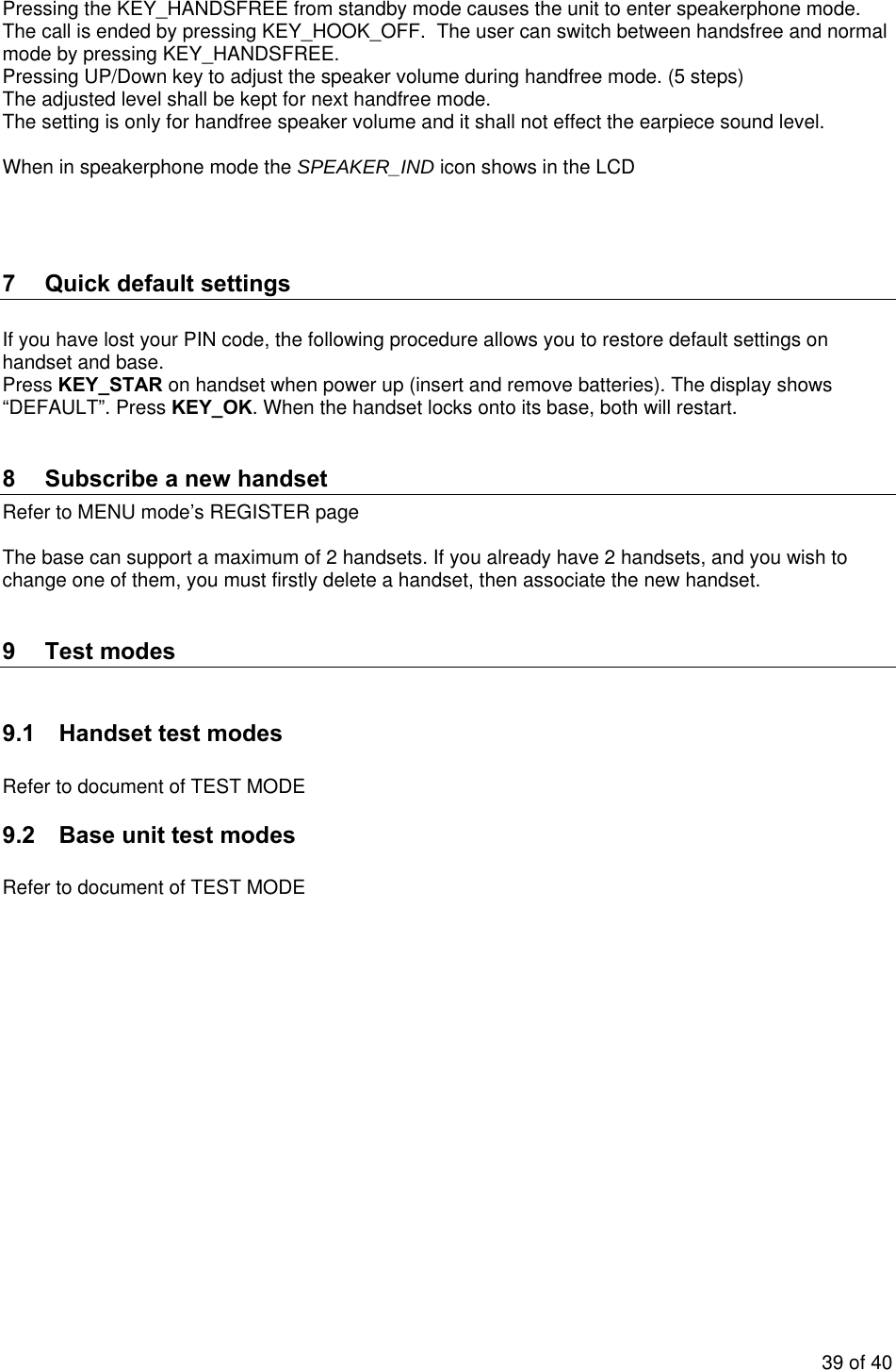
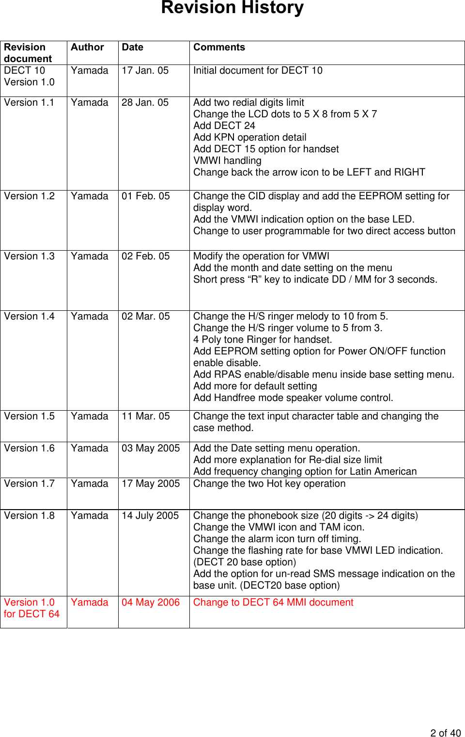
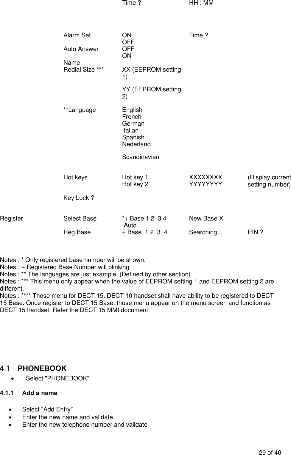
![The call timer display will come again after 15 seconds if no key pressed. During standby mode: The icon will flash if un-viewed unanswered CLIP(s) in call list, icon will be off after all unanswered call is read. 3.7.3 VMWI indication Refer to the VMWI operation 3.7.4 Recall CLIP list Unanswered and answered calls are stored in the CLIP list of each handset independently (in EEPROM). Note: any new CLIP call will be stored in EEPROM . Size storage Each entry will store: ¾ The call number (20 digits) ¾ The caller name (12 digits) if the network send it ¾ The date and hour of the call Storage sequence The CLIP information that has been received during incoming alert phase (calling number, name date/hour) is stored then displayed. If the new call entries, The icon will flash (480ms ON/OFF) and will off after all new call is read. Note: The new message indication is reset at power up, so the icon is always off after a reset. MMI operation To retrieve the entries: 1. Press KEY_ UP/CLIP or KEY_ DOWN/CLIP to enter the call list. The icon will stay ON for Unanswered Calls and the icon will stay ON for Answered Calls. If the list is already empty, then “EMPTY” is displayed on the 1st line 2. [Display example] 3. Scroll through the calls using the up KEY_UP/CLIP and down KEY_DOWN/CLIP arrows. 4. You will find the different fields of the entry: 21 of 40](https://usermanual.wiki/Sun-Communications/DECT64-S96-B11/User-Guide-746737-Page-24.png)
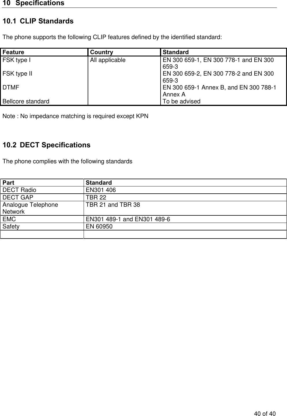
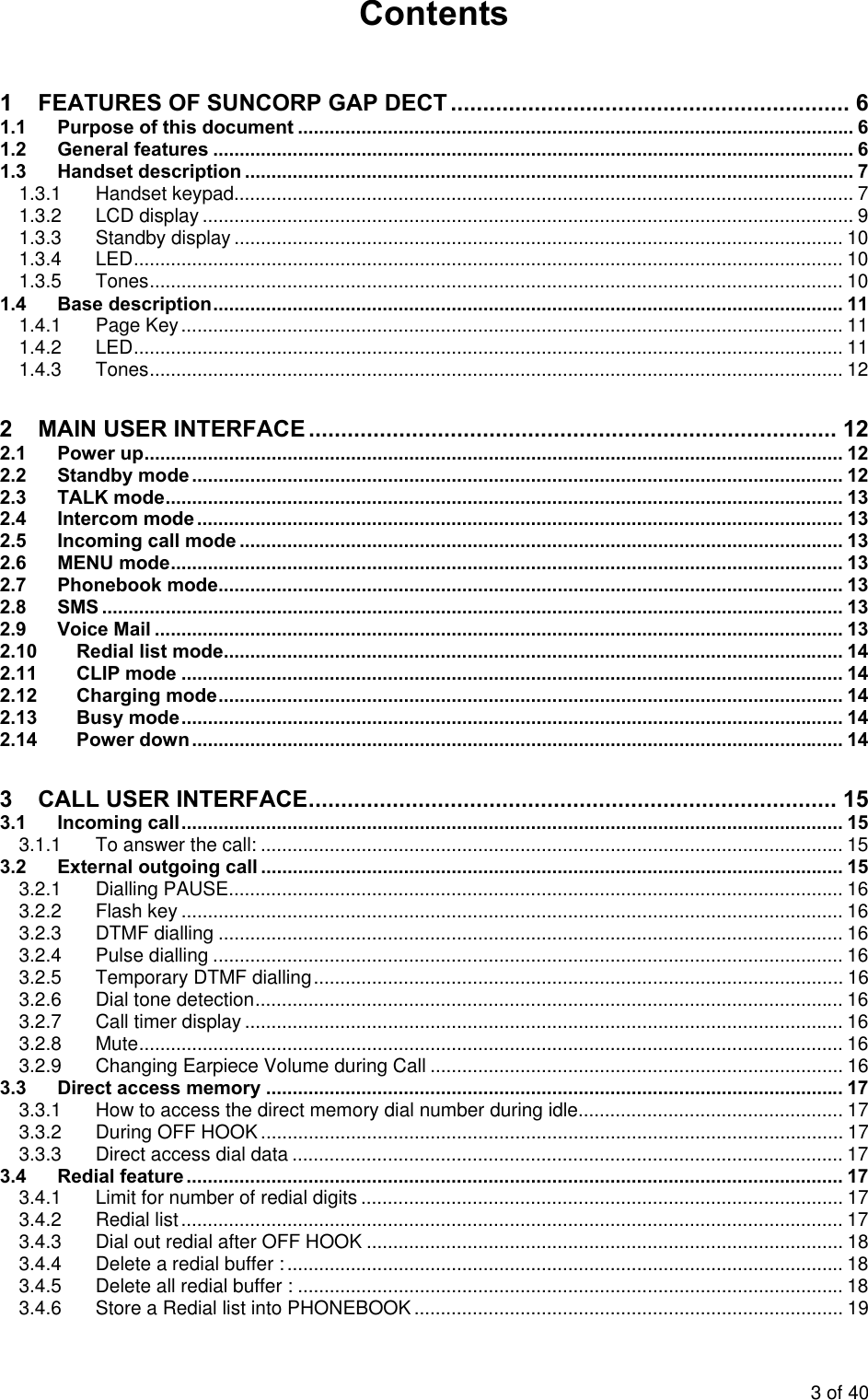
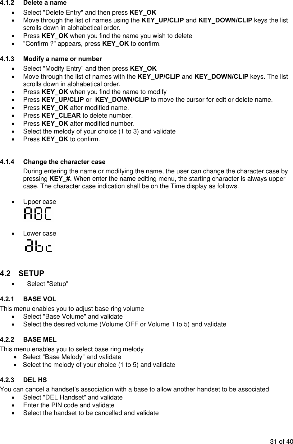
![• To detect line reverse, the unit shall detect PSTN line 1 and line 2 both polarity changing within 10mS. If only one line polarity changing, it should not be polarity changing. It should be line voltage interruption. • After finish the call and go to idle stage, the unit shall not detect line reverse for about 100mS from line releasing point. • DC load shall be 90Kohm - 110Kohm. • AC load impedance in the voice band shall be greater than 1800ohm and preferable lower than 2400ohm. 3.7.9.2 DC/AC load release • After detect the line reversal, if the unit does not detect the CID DTMF signal within 1S. • During receiving the DTMF, if detect the DTMF pause for more than 1 S. • When received the DTMF ‘C” (Stop code). • Ringer signal is received. • OFF HOOK the telephone 3.7.9.3 DTMF signal detection • A valid DTMF signal > 40mS shall be interpreted as a valid digit. • A valid DTMF signal < 40mS shall not be interpreted as a valid digit. • If not valid DTMF signal is present during > 40mS, this shall be interpreted as an inter digit pause. • If not valid DTMF signal is present during < 40mS, this shall not be interpreted as an inter digit pause. • A level > 37mV shall be recognized as a valid digit. • A level < 28mV shall not be recognized as a valid digit. 3.8 Phonebook The phonebook contains up to 50 names of 12 characters max. and numbers of 24 digits. Phonebook is stored in PP EEPROM. One handset phonebook is independent from other locked handsets. 3.8.1 Dial a number of the phonebook list To call a correspondent whose name you have saved in the phonebook: • Press KEY_MEM/EXIT to enter the phonebook. The will be ON. [Display example] • Press the first letter of the name; the first name that starts with this letter in the alphabet appears. For instance to find names beginning by A, press once on KEY_2, to find names beginning by B, press twice on KEY_2, to find names beginning by C, press three times on KEY_2 23 of 40](https://usermanual.wiki/Sun-Communications/DECT64-S96-B11/User-Guide-746737-Page-26.png)
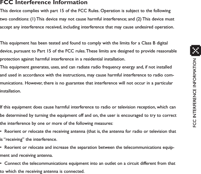
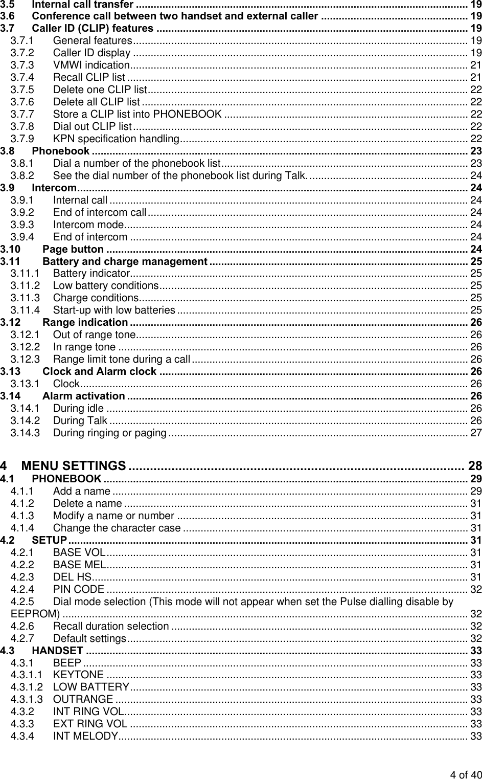
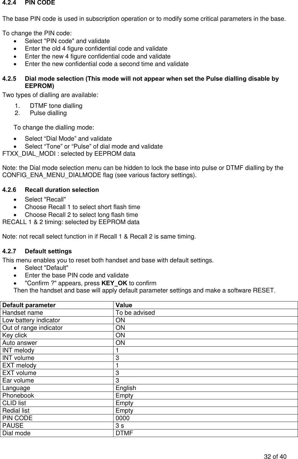
![• It is possible to enter the following data for number entering. - KET_1 to KEY_0 - KEY_STAR and KEY_# - KEY_LNR (Pause) - KEY_R (Recall, Flash) • Select the melody of your choice (1 to 3) and validate • Press KEY_OK to confirm. With your telephone you can write text as well as figures. This is useful for entering a name into the address book, giving a name to a handset, … To select a letter, press the corresponding key as many times as is necessary. For example to select an 1, press 2 once, to select a B, press 2 twice and so on. To select A and then B consecutively, select a 1, wait until the cursor moves on to the next character, then select a B. Select Upper case 1 . , - ? ! ` @ : ; 1 2 A B C 2 Ä Å Æ 3 D E F 3 É ∆ Φ 4 G H I 4 Γ 5 J K L 5 Λ 6 M N O 6 Ñ Ö Ø Ω 7 P Q R S 7 Π Ψ Σ 8 T U V 8 Ü Θ 9 W X Y Z 9 Ξ 0 (Space) 0 * * # Change the case Lower case 1 . , - ? ! ` @ : ; 1 2 a b c 2 ä à å æ ç 3 d e f 3 è é 4 g h i 4 ì 5 j k l 5 6 m n o 6 ñ ò ö ø 7 p q r s 7 β 8 t u v 8 ù ü 9 w x y z 9 0 (Space) 0 * * # Change the case The following symbols need to be under “0” and “*” . ( ) & " \ / _ [ ] $ ¥ £ € % + * = ~ < > # | ^ ¡ ¿ § ¤ { } 30 of 40](https://usermanual.wiki/Sun-Communications/DECT64-S96-B11/User-Guide-746737-Page-33.png)
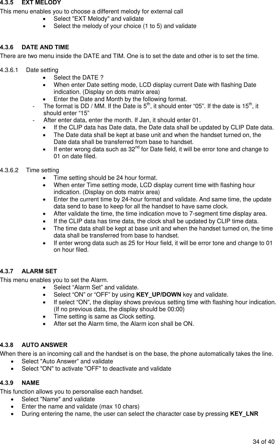
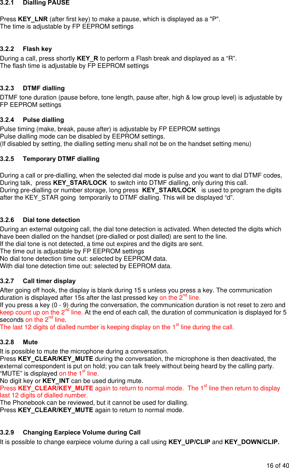
![Key lock OFF Clock 00:00 Alarm OFF Date Jan 1st RPAS enable /disable Enable Handfree mode speaker volume 3 (Only for DECT 24) RPAS length setting 400mA Recall setting Recall 1 Redial size 32 Handset Name Handset Hot key 1 number XXXXXXXXXX (TBA) Hot key 2 number XXXXXXXXXX (TBA Default values in handset and base are defined by EEPROM settings [1]. So they can be adjusted for each country. 4.3 HANDSET • Select "Handset" 4.3.1 BEEP Beep features The handsets may or may not emit beeps while the keys are pressed , the batteries are low and when the handset is out of range of the base. 4.3.1.1 KEYTONE • Select "Key Tone" and validate • Select “ON” or “OFF” and validate 4.3.1.2 LOW BATTERY • Select "Low Battery" and validate • Select “ON” or “OFF” and validate 4.3.1.3 OUTRANGE • Select "Out Range" and validate • Select “ON” or “OFF” and validate 4.3.2 INT RING VOL This menu enables you to adjust handset ring volume (intern melody) • Select "INT Ring Vol" and validate • Select the desired volume (Volume OFF or Volume 1 to 5) and validate 4.3.3 EXT RING VOL This menu enables you to adjust handset ring volume (extern melody) • Select "EXT Ring Vol" and validate • Select the desired volume (Volume OFF or Volume 1 to 5) and validate 4.3.4 INT MELODY This menu enables you to choose a different melody for internal call • Select "INT Melody" and validate • Select the melody of your choice (1 to 5) and validate 33 of 40](https://usermanual.wiki/Sun-Communications/DECT64-S96-B11/User-Guide-746737-Page-36.png)