Sun Communications DECT64-S96-B11 US DECT PHONE- BASE User Manual SunCorp Generic GAP Specification
SunCorp Communications Limited US DECT PHONE- BASE SunCorp Generic GAP Specification
USERS MANUAL

DECT 64-S96+B11 GAP
MMI Specification
Document Version 1.0
1 of 40
FCC INTERFERENCE INFORMATION
x
FCC Interference Information
This device complies with part 15 of the FCC Rules. Operation is subject to the following
two conditions: (1) This device may not cause harmful interference; and (2) This device must
accept any interference received, including interference that may cause undesired operation.
This equipment has been tested and found to comply with the limits for a Class B digital
device, pursuant to Part 15 of the FCC rules.These limits are designed to provide reasonable
protection against harmful interference in a residential installation.
This equipment generates, uses, and can radiate radio frequency energy and, if not installed
and used in accordance with the instructions, may cause harmful interference to radio com-
munications. However, there is no guarantee that interference will not occur in a particular
installation.
If this equipment does cause harmful interference to radio or television reception, which can
be determined by turning the equipment off and on, the user is encouraged to try to correct
the interference by one or more of the following measures:
• Reorient or relocate the receiving antenna (that is, the antenna for radio or television that
is “receiving” the interference.
• Reorient or relocate and increase the separation between the telecommunications equip-
ment and receiving antenna.
• Connect the telecommunications equipment into an outlet on a circuit different from that
to which the receiving antenna is connected.
FCC RF Radiation Exposure Statement
The installation of the base unit should allow at least 20 centimeter between the base and
persons in compliance with FCC RF exposure guidelines. For body worn operation, the
portable part (handset) has been tested and meets FCC RF exposure guidelines.
This device must not be co-located or operating in conjunction with any other antenna or
transmitter.The changes or modifications not expressly approved by the party responsible for
compliance could void user’s authority to operate the equipment.
FCC Part 15.19
FCC Part 15.21
FCC Part 15.105(b)
FCC Part 2.1091
FCC Part 2.1093

6
ongratulations on your selection of this quality product by XACT Communication.
With proper care and adherence to the set-up and user instructions in this Owner's
Manual, this unit will provide you with years of trouble-free service. XACT is
committed to providing quality products that fit your needs.We would like to have
any comments or suggestions you might have on this product.You may mail your
comments to:
XACT Communication, LLC
105 Madison Avenue
New York, NY 10016
info@xactcommunication.com
WHAT’S IN THE BOX?
User manual
Edge 1.4 handset
Edge 1.4 base station
Line cord
Power adapter for base station
Battery door
2 x AAA rechargeable batteries
Warranty information
In the event that any item is missing or if you find any mismatch or damage,
promptly contact your retailer.
C

Revision History
Revision
document
Author Date Comments
DECT 10
Version 1.0 Yamada 17 Jan. 05 Initial document for DECT 10
Version 1.1 Yamada 28 Jan. 05 Add two redial digits limit
Change the LCD dots to 5 X 8 from 5 X 7
Add DECT 24
Add KPN operation detail
Add DECT 15 option for handset
VMWI handling
Change back the arrow icon to be LEFT and RIGHT
Version 1.2 Yamada 01 Feb. 05 Change the CID display and add the EEPROM setting for
display word.
Add the VMWI indication option on the base LED.
Change to user programmable for two direct access button
Version 1.3 Yamada 02 Feb. 05 Modify the operation for VMWI
Add the month and date setting on the menu
Short press “R” key to indicate DD / MM for 3 seconds.
Version 1.4 Yamada 02 Mar. 05 Change the H/S ringer melody to 10 from 5.
Change the H/S ringer volume to 5 from 3.
4 Poly tone Ringer for handset.
Add EEPROM setting option for Power ON/OFF function
enable disable.
Add RPAS enable/disable menu inside base setting menu.
Add more for default setting
Add Handfree mode speaker volume control.
Version 1.5 Yamada 11 Mar. 05 Change the text input character table and changing the
case method.
Version 1.6 Yamada 03 May 2005 Add the Date setting menu operation.
Add more explanation for Re-dial size limit
Add frequency changing option for Latin American
Version 1.7 Yamada 17 May 2005 Change the two Hot key operation
Version 1.8 Yamada 14 July 2005 Change the phonebook size (20 digits -> 24 digits)
Change the VMWI icon and TAM icon.
Change the alarm icon turn off timing.
Change the flashing rate for base VMWI LED indication.
(DECT 20 base option)
Add the option for un-read SMS message indication on the
base unit. (DECT20 base option)
Version 1.0
for DECT 64 Yamada 04 May 2006 Change to DECT 64 MMI document
2 of 40
Contents
1 FEATURES OF SUNCORP GAP DECT .............................................................. 6
1.1 Purpose of this document ......................................................................................................... 6
1.2 General features ......................................................................................................................... 6
1.3 Handset description ................................................................................................................... 7
1.3.1 Handset keypad..................................................................................................................... 7
1.3.2 LCD display ........................................................................................................................... 9
1.3.3 Standby display ................................................................................................................... 10
1.3.4 LED...................................................................................................................................... 10
1.3.5 Tones................................................................................................................................... 10
1.4 Base description....................................................................................................................... 11
1.4.1 Page Key............................................................................................................................. 11
1.4.2 LED...................................................................................................................................... 11
1.4.3 Tones................................................................................................................................... 12
2 MAIN USER INTERFACE .................................................................................. 12
2.1 Power up.................................................................................................................................... 12
2.2 Standby mode ........................................................................................................................... 12
2.3 TALK mode................................................................................................................................ 13
2.4 Intercom mode .......................................................................................................................... 13
2.5 Incoming call mode .................................................................................................................. 13
2.6 MENU mode............................................................................................................................... 13
2.7 Phonebook mode...................................................................................................................... 13
2.8 SMS ............................................................................................................................................ 13
2.9 Voice Mail .................................................................................................................................. 13
2.10 Redial list mode..................................................................................................................... 14
2.11 CLIP mode ............................................................................................................................. 14
2.12 Charging mode...................................................................................................................... 14
2.13 Busy mode............................................................................................................................. 14
2.14 Power down ........................................................................................................................... 14
3 CALL USER INTERFACE.................................................................................. 15
3.1 Incoming call............................................................................................................................. 15
3.1.1 To answer the call: .............................................................................................................. 15
3.2 External outgoing call .............................................................................................................. 15
3.2.1 Dialling PAUSE.................................................................................................................... 16
3.2.2 Flash key ............................................................................................................................. 16
3.2.3 DTMF dialling ...................................................................................................................... 16
3.2.4 Pulse dialling ....................................................................................................................... 16
3.2.5 Temporary DTMF dialling.................................................................................................... 16
3.2.6 Dial tone detection............................................................................................................... 16
3.2.7 Call timer display ................................................................................................................. 16
3.2.8 Mute..................................................................................................................................... 16
3.2.9 Changing Earpiece Volume during Call .............................................................................. 16
3.3 Direct access memory ............................................................................................................. 17
3.3.1 How to access the direct memory dial number during idle.................................................. 17
3.3.2 During OFF HOOK.............................................................................................................. 17
3.3.3 Direct access dial data ........................................................................................................ 17
3.4 Redial feature ............................................................................................................................ 17
3.4.1 Limit for number of redial digits ........................................................................................... 17
3.4.2 Redial list............................................................................................................................. 17
3.4.3 Dial out redial after OFF HOOK .......................................................................................... 18
3.4.4 Delete a redial buffer :......................................................................................................... 18
3.4.5 Delete all redial buffer : ....................................................................................................... 18
3.4.6 Store a Redial list into PHONEBOOK ................................................................................. 19
3 of 40
3.5 Internal call transfer ................................................................................................................. 19
3.6 Conference call between two handset and external caller .................................................. 19
3.7 Caller ID (CLIP) features .......................................................................................................... 19
3.7.1 General features.................................................................................................................. 19
3.7.2 Caller ID display .................................................................................................................. 19
3.7.3 VMWI indication................................................................................................................... 21
3.7.4 Recall CLIP list .................................................................................................................... 21
3.7.5 Delete one CLIP list............................................................................................................. 22
3.7.6 Delete all CLIP list ............................................................................................................... 22
3.7.7 Store a CLIP list into PHONEBOOK ................................................................................... 22
3.7.8 Dial out CLIP list.................................................................................................................. 22
3.7.9 KPN specification handling.................................................................................................. 22
3.8 Phonebook ................................................................................................................................ 23
3.8.1 Dial a number of the phonebook list.................................................................................... 23
3.8.2 See the dial number of the phonebook list during Talk....................................................... 24
3.9 Intercom..................................................................................................................................... 24
3.9.1 Internal call .......................................................................................................................... 24
3.9.2 End of intercom call............................................................................................................. 24
3.9.3 Intercom mode..................................................................................................................... 24
3.9.4 End of intercom ................................................................................................................... 24
3.10 Page button ........................................................................................................................... 24
3.11 Battery and charge management ........................................................................................ 25
3.11.1 Battery indicator................................................................................................................... 25
3.11.2 Low battery conditions......................................................................................................... 25
3.11.3 Charge conditions................................................................................................................ 25
3.11.4 Start-up with low batteries................................................................................................... 25
3.12 Range indication ................................................................................................................... 26
3.12.1 Out of range tone................................................................................................................. 26
3.12.2 In range tone ....................................................................................................................... 26
3.12.3 Range limit tone during a call.............................................................................................. 26
3.13 Clock and Alarm clock ......................................................................................................... 26
3.13.1 Clock.................................................................................................................................... 26
3.14 Alarm activation .................................................................................................................... 26
3.14.1 During idle ........................................................................................................................... 26
3.14.2 During Talk .......................................................................................................................... 26
3.14.3 During ringing or paging...................................................................................................... 27
4 MENU SETTINGS .............................................................................................. 28
4.1 PHONEBOOK ............................................................................................................................ 29
4.1.1 Add a name ......................................................................................................................... 29
4.1.2 Delete a name ..................................................................................................................... 31
4.1.3 Modify a name or number ................................................................................................... 31
4.1.4 Change the character case ................................................................................................. 31
4.2 SETUP........................................................................................................................................ 31
4.2.1 BASE VOL........................................................................................................................... 31
4.2.2 BASE MEL........................................................................................................................... 31
4.2.3 DEL HS................................................................................................................................ 31
4.2.4 PIN CODE ........................................................................................................................... 32
4.2.5 Dial mode selection (This mode will not appear when set the Pulse dialling disable by
EEPROM) .......................................................................................................................................... 32
4.2.6 Recall duration selection ..................................................................................................... 32
4.2.7 Default settings.................................................................................................................... 32
4.3 HANDSET .................................................................................................................................. 33
4.3.1 BEEP................................................................................................................................... 33
4.3.1.1 KEYTONE ........................................................................................................................... 33
4.3.1.2 LOW BATTERY................................................................................................................... 33
4.3.1.3 OUTRANGE ........................................................................................................................33
4.3.2 INT RING VOL..................................................................................................................... 33
4.3.3 EXT RING VOL ................................................................................................................... 33
4.3.4 INT MELODY....................................................................................................................... 33
4 of 40
4.3.5 EXT MELODY ..................................................................................................................... 34
4.3.6 DATE AND TIME................................................................................................................. 34
4.3.7 ALARM SET ........................................................................................................................ 34
4.3.8 AUTO ANSWER.................................................................................................................. 34
4.3.9 NAME .................................................................................................................................. 34
4.3.10 KEY LOCK........................................................................................................................... 35
4.3.10.1 Quick KEY LOCK ................................................................................................................ 35
4.3.10.2 To unlock key: ..................................................................................................................... 35
4.4 REGISTER ................................................................................................................................. 35
4.4.1 SELECT BASE.................................................................................................................... 35
4.4.2 REG BASE .......................................................................................................................... 35
5 PREFIX DIALLING............................................................................................. 36
5.1 Detect string.............................................................................................................................. 36
5.2 Replace string ........................................................................................................................... 36
5.3 Detecting and replacement...................................................................................................... 36
6 DECT 24 ADDENDUM (SET THE EEPROM SETTING FOR DECT 24) ........... 37
6.1 Change to Handset keypad layout.......................................................................................... 37
6.1.1 LCD display ......................................................................................................................... 38
7 QUICK DEFAULT SETTINGS ........................................................................... 39
8 SUBSCRIBE A NEW HANDSET ....................................................................... 39
9 TEST MODES .................................................................................................... 39
9.1 Handset test modes.................................................................................................................. 39
9.2 Base unit test modes ............................................................................................................... 39
10 SPECIFICATIONS........................................................................................... 40
10.1 CLIP Standards ..................................................................................................................... 40
10.2 DECT Specifications.............................................................................................................40
5 of 40

1 Features of SunCorp GAP DECT
1.1 Purpose of this document
The purpose of this document is to describe the specifications and the MMI of the product. It includes
information about :
• Hardware and software features
• User interface description
• User settings
1.2 General features
General features
Phonebook of 50 entries
Search by name
20 last numbers redial
Different melody for internal and external calls
Automatic answering when taking the handset from the
base
Automatic phone off when placing the handset on
cradle
Mute key
Pre-dialling
Dialling mode changing during conversation
User friendly menu
Display length of conversation
Sixteen languages
PIN code for set-up
Page function
Select earpiece volume (Total 5 step)
Select ringer volume (Total 5 steps)
10 different melodies for handset
4 poly tone ringer for handset
5 different melody for base
Out of range tone
Battery warning tone
Customisable name of each handset
5 Portable Parts per base
4 Fixed Parts per handset
Clock on the handset
Alarm clock on the handset
3-Way conference call
*Caller ID Type I & II
*CLIP type I & II FSK (ETSI) & DTMF (KPN)
* Bellcore CLIP
Display caller name*
List of last 40 calls
Time stamped calls
Redial last outgoing number
Display caller number during conversation
Two maximum digits limit for last number redial
The handset has compatibility for DECT 65 (Auto
detect)
Intercom
Free intercom between handsets
Transfer a call to another handset
Option functions (Set by EEPROM)
Two direct access keys
Prefix dialling number
Power ON/OFF function
Frequency option for DECT 6.0 and Euro DECT
Hardware option
Backlight LCD
Backlight key board
LED for Talk and incoming ring
Line reverse detection for KPN** (Option)
**VMWI indication
*Only if the function is supported by the network and type II is option
** Only if the function is supported by the network
6 of 40

1.3 Handset description
1.3.1 Handset keypad
Some keys have more than one usage depending on the MMI state (standby, in call, menu mode).
The table hereafter gives all the possible actions for each key. In the following chapters, the reference
for one key will be indicated with the main action of the key. Sometimes the second (or third) meaning
will be indicated as follows: KEY_USE1/KEY_USE2.
Talk mode Menu mode
Key name Standby
mode
Incoming
call
From
incoming call
Outgoing call Phoneboo
k mode
KEY_MENU/OK
MENU
Enter menu Confirm Confirm
KEY_LNR
Redial/Pause
Enter Redial
list
Pause Redial (first key in
call)
Pause (after first
key)
Pause
KEY_UP/CLIP
▲
Enter
CLIP list Ringer
volume up Receiver Volume
Up Receiver Volume
Up Choose Choose
KEY_DOWN/CLIP
▼
Enter
CLIP list
Ringer
volume down Receiver Volume
Down Receiver Volume
Down Choose Choose
KEY_MEM/EXIT
Enter
Phonebook Enter
Phonebook Exit Exit
KEY_CLEAR
X
Toggle Mute Toggle Mute Clear Clear
KEY_HOOK
Go in TALK
mode Go in TALK
mode Standby mode Standby mode
KEY_INT
Int
Intercom Transfer the call
Transfer the call
KEY_R/POWER
R
Power off
(hold)
Change to
DD / MM
display for 3
seconds
(Short press)
Flash Flash
KEY_0
0
Pre-dial 0 Dial 0 Dial 0 0
KEY_1
1
Pre-dial 1
(DDK1:Long) Dial 1 Dial 1 1
KEY_2
2
Pre-dial 2
(DDK2:Long) Dial 2 Dial 2 2
KEY_3
3
Pre-dial 3 Dial 3 Dial 3 3
KEY_4
4
Pre-dial 4 Dial 4 Dial 4 4
7 of 40

KEY_5
5
Pre-dial 5 Dial 5 Dial 5 5
KEY_6
6
Pre-dial 6 Dial 6 Dial 6 6
KEY_7
7
Pre-dial 7 Dial 7 Dial 7 7
KEY_8
8
Pre-dial 8 Dial 8 Dial 8 8
KEY_9
9
Pre-dial 9 Dial 9 Dial 9 9
KEY_STAR
*
Pre-dial *
Dial *
Go into DTMF
ode from pulse m
Dial *
Go into DTMF
ode from pulse m
*
KEY_HASH/LOCK
#
Pre-dial #
Toggle key
lock (Hold)
#
Short press is less than 1 second
Long press is more than 1.5 second
Hold is press and hold more than 3 seconds
8 of 40
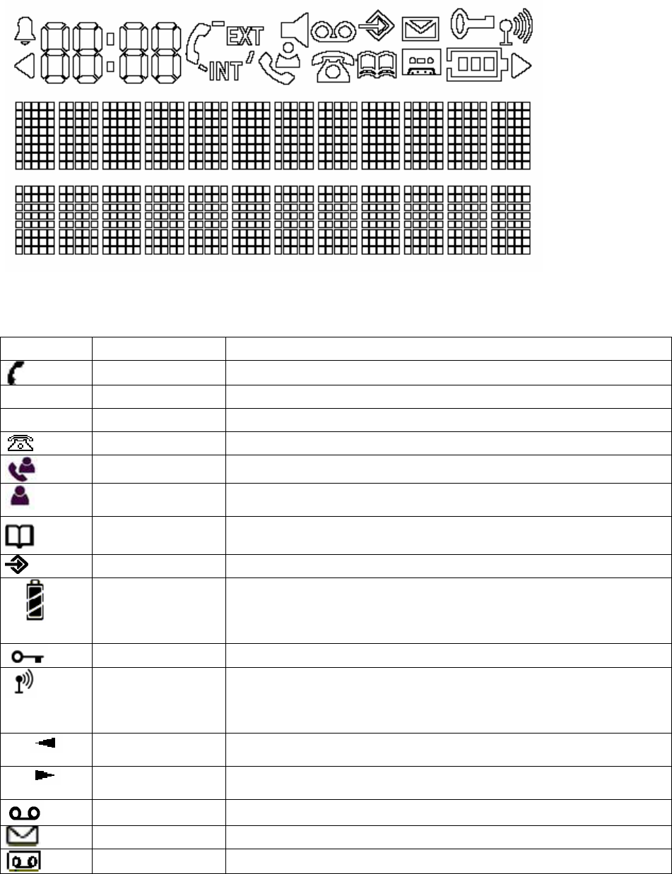
1.3.2 LCD display
The LCD display is composed of 12 characters dots matrix form (8 X 5 matrix), 4 characters 7
segments and 18 icons. (Icon drawings are just reference only. Plesae refere to the LCD specification)
The definition of the icons is as follows:
(Icons are just reference only)
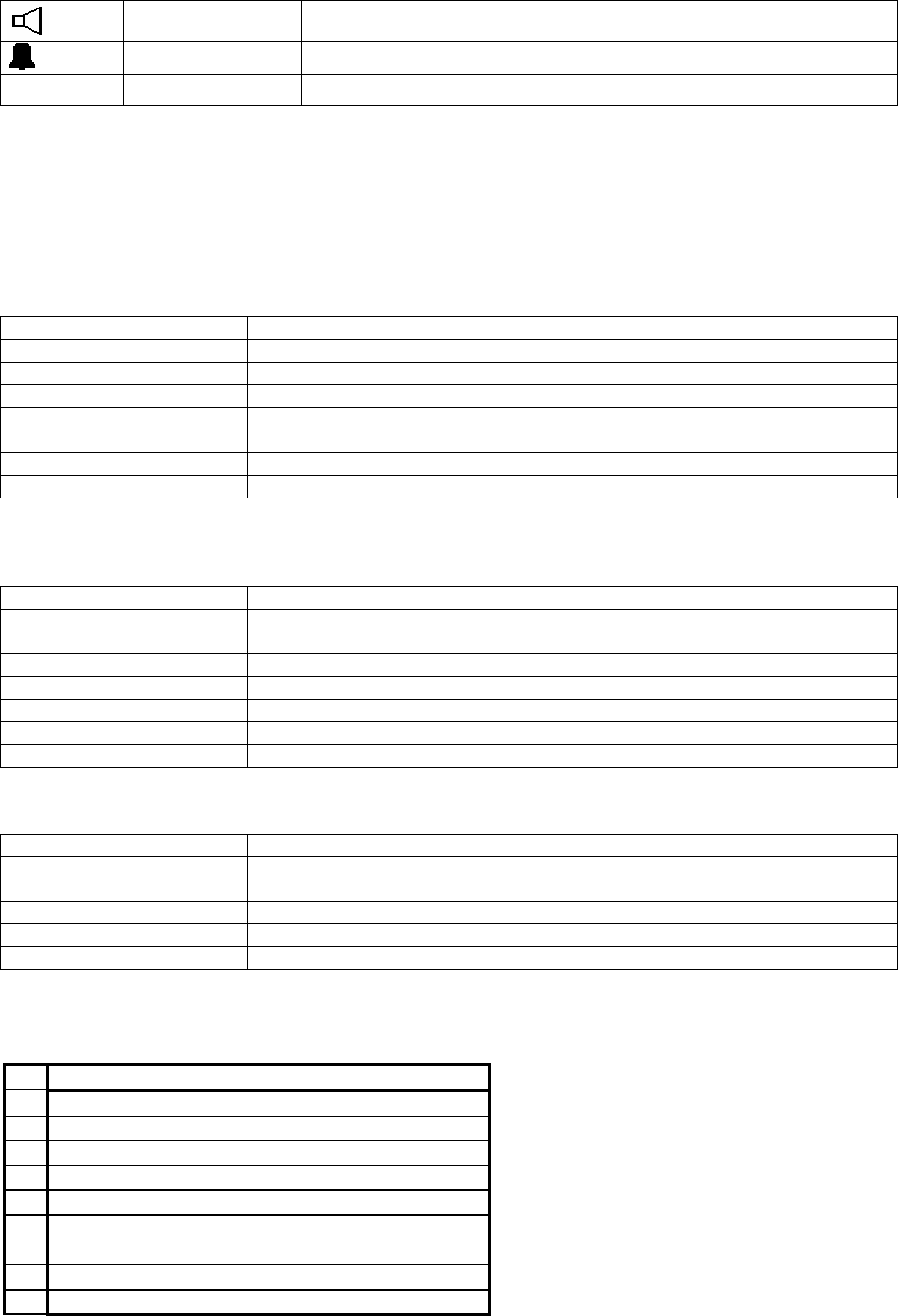
Icon NAME Definition
HOOK_IND Off hook indicator
EXT EXT External call engaged
INT INT Internal call engaged
NEW_CLIP_IND Caller identification available /new numbers in calls list
CLIP_ANSWERED Indicate answered call
CLIP_UNANSWER
ED Indicate unanswered call
PHONEBOOK_IND Phonebook indicator
MENU_IND Menu indicator
BATTERY 3 levels battery indicator
1 segment: weak, 2 segments: medium, 3 segments: full
The segments scroll during battery recharging and stop scrolling
when battery is full
LOCK_IND Handset keypad locked
ANTENNA Signal strength indicator.
The icon is steady when handset is locked to its base
The icon flashes when the handset is unlocked or not subscribed to
any base
LEFT_ARROW Indicates that displayed number or message is longer than the
screen (12 digits)
RIGHT_ARROW Indicates that displayed number or message is longer than the
screen (12 digits)
TAM_MSG VMWI indication
NEW_SMS_IND New SMS message indication
VMWI_IND This is for DECT 65
9 of 40
HAND_FREE Hand free indicator. This is for DECT 10-SP
ALARM_SET Alarm set indicator
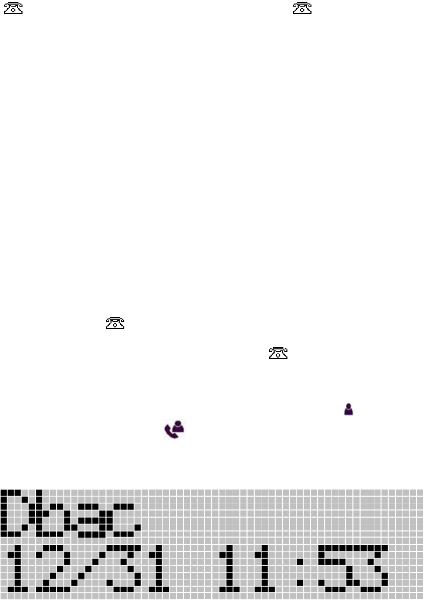
1.3.3 Standby display
In standby mode, the display shows the handset name (Maximum 10 characters) and the handset
number (Last 1 digit). Also, the current time on the Time display (24 hours indication)
1.3.4 LED
• Talk LED
Action LED state
Standby mode OFF
Subscription mode Flash
In call Flash
Incoming call Flash synchronized with PSTN ring pattern.
New CID OFF
New SMS Flash (Not for DECT 6.0)
Voice mail notification Flash
• Key backlight LED (Hardware Option)
Action LED state
Standby mode (No key
press) OFF
Press any key ON for 8 seconds after press last key (Setting by EEPROM)
During key lock OFF
Incoming call Flash (0.5s ON/OFF)
External call ON
External call on hold Flash (0.5s ON/OFF)
• LCD backlight LED and Key backlight LED (Hardware Option)
Action LED state
Standby mode (No key
press) OFF
Press any key ON for 8 seconds after press last key (Setting by EEPROM)
During key lock OFF
Incoming call ON
1.3.5 Tones
Nr Name
1 Ring 1
2 Ring 2
3 Ring 3
4 Ring 4
5 Ring 5
6 Ring 6
7 Ring 7
8 Ring 8
9 Ring 9
10 of 40
10 Ring 10
6 TONE_CONFIRM
7
8
9 TONE_LOW_BATT
10 TONE_FREE
11 TONE_CALL_WAITING
12 TONE_BUSY
13 TONE_ERROR
14 TONE_IN_RANGE
15 TONE_WARNING
16 TONE_OFF_HOOK_WARNING
17 TONE_RING_BACK
18 TONE_ALARM_CLOCK
1.4 Base description
1.4.1 Page Key
Key action MMI action
Short press (<5 s) Send a page to handsets
Long Press (>=5s) Enters subscription mode (in use LED will flash)
1.4.2 LED
Power/In use LED
Action LED state
Standby mode ON
Subscription mode Flash
In call Flash
Incoming call Flash synchronized with PSTN ring pattern.
New SMS message Flash (Not for DECT 6.0)
### Add the EEPROM setting (FP) to enable the VMWI indication on the base unit.
Especially for Australia, it is better to have VMWI on the base unit. It should enable or disable this
function by EEPROM setting.
(If there is not only one Voice mail server, this function shall be disabled by EEPROM setting)
Operation:
- Receive the CID data (Parameter type 0Bh + Data FFh), and then activate the base IN-USE LED
to be flash.
- The Flashing rate is 0.2S - 0.25S ON/OFF
- This Flashing is lower priority, so, any other operation to turn ON the IN-USE LED, those
operation have priority.
- The Flashing is keeping until received the CID data (Parameter type 0Bh + Data 00h) regardless
the unit goes to oh-hook or off-hook.
11 of 40

- The VMWI signal may be contained Type 2 CID data. So, during Talk mode and received the
(Parameter type 0Bh + Data FFh), the information will be kept and once the unit goes to standby,
then the IN-USE LED starts to flash.
1.4.3 Tones
The three base melodies are shown in the following table
Nr Name
1 Ring 1
2 Ring 2
3 Ring 3
4 Ring 4
5 Ring 5
6 TONE_CONFIRM
2 Main User interface
2.1 Power up
Plug the power supply into the base. The in use LED will be turned on and TONE_CONFIRM.
Insert batteries in the handset. If battery level is enough (see Start up with low batteries chapter), the
handset will start.
The display will show “Base 1” and antenna flashing, until it locks onto its subscribed base. If the
handset finds its base in the first 10 seconds, no beeps are played (see Range indication chapter).
Then the display shows the standby display.
2.2 Standby mode
In standby mode, the display shows the handset name and the handset number.
The ANTENNA icon is steady. The BATTERY icon indicates the charge level.
Handset:
Events Handset mode
Press KEY_HOOK Enter TALK mode
Press KEY_INT Enter intercom mode
Press KEY_MENU Enter MENU mode
Press KEY_MEM Enter phonebook mode
Press KEY_HASH /LOCK
(hold 3 second) Enter KEY LOCK mode
Press KEY_LNR/PAUSE Enter redial list mode
Press KEY_UP/CLIP or
KEY_DOWN/CLIP Enter CLIP mode
Press KEY_R/POWER
(hold 3 second) Enter power down mode
Press 1,2,3……0,*,# Pre-dialling
Incoming call signal Incoming call mode
Another handset TALK Busy mode
Battery is low Battery low icon
Battery is too low Power down mode
On charging Charging mode
12 of 40

Long press for 1 or 2 Access direct pre-programmed
number
Base:
Events Base mode
Press PAGE KEY Enter PAGE mode
Incoming call signal Incoming call mode
2.3 TALK mode
Refer to External outgoing call
2.4 Intercom mode
Refer to intercom
2.5 Incoming call mode
Refer to incoming call
2.6 MENU mode
Refer to MENU settings
2.7 Phonebook mode
Refer to phonebook
2.8 SMS
Refer to SMS MMI document
2.9 Voice Mail
An indication is given to user when voicemail is waiting, called the VMWI (Voice Mail Waiting
Indication)
VMWI notification/de-notification can be received from multiple voicemail server. Matching of VMWI
notification/de-notification will be done using number field.
On receipt of a VMWI “ON” message
• The VMWI notification will be stored in to the CID list.
• Each entry will show the CID of the voice mail server number, including box number if provided.
• The name of the voice mail server, as sent in the “Name” field will also be stored in CID list along
with the Date/Time of the call. The Name field can receive up to 50 characters, but the display will
be truncated to 12 characters.
• Note that no additional VMWI will be added to the list, if the server number is already existing on
the CID list, but in this case the date and time shall be updated on the existing entry on the CID list.
• The icon will be flash.
• Note that the CID list operate as a FIFO buffer. If the CID list is full, on receipt of a new notification,
it will replace the oldest non-VMWI item in the CID list. (If oldest one is VMWI item, it shall not be
erased)
• To access the voicemail server, the user can press KEY_TALK whilst the VMWI is displayed in
the CID list.
On receipt of a VMWI “OFF” message
• If the -de-notification matches and item already on the CID list, then the notification will be
removed from the list.
13 of 40

• If the item does not exist on the list, then the de-notification which has number will be ignored.
However, if the icon is flashing and received de-notification does not have number, and
there is no notification on the list, the icon will be removed.
• When remove the notification and after remove the notification, if no other notifications are remain
in the list, the icon will be removed.
• When receive the VMWI notification without server number, the icon shall start to flash.
However, the notification shall not be stored to the call list.
• When receive the VMWI de-notification without server number, the icon will be removed if
no notifications are in the list.
• Any kind of de-notification shall not be stored to call list.
• The user can manually turn off the display of icon, by a long press of “5”, whilst viewing CID
list. (It will effect to other handset and base also delete all the notification on the list)
• The user can manually remove VMWI notification from the CID list using delete function. When
removed the notification and the notification was last one, the icon will be removed. (It will
not effect to other handset and base)
Note:
• The VMWI data “0Bh + FFh or 00h” shall be received regardless Data link message such as “80h
or 82h”.
2.10 Redial list mode
Refer to redial features
2.11 CLIP mode
Refer to Caller ID (CLIP) feature
2.12 Charging mode
Refer to Charging conditions
2.13 Busy mode
When one Handset is TALK, another handset’s “EXT” icon, and TONE_BUSY in earpiece if press
KEY_HOOK
2.14 Power down
Make a long press on KEY_R/POWER, and the handset power down.
Press and hold KEY_R/POWER for 5 seconds to wake it up. When the handset wakes up, the clock
time data shall be transferred from base.
This function can be enable or disabled by EEPROM setting
14 of 40

3 Call User interface
3.1 Incoming call
The Phone should not ring when receiving a burst of notification. The network will send RPAS and
caller ID in short period of time (at 4 seconds interval)
Display
The display shows "Call" on the 1st line and EXT icon blinks (0.5 s ON/OFF), if caller ID information is
available (see 3.5), the caller name and number is displayed. The caller name is on the 1st line and
number is on the 2nd line. (If the name is not available, only number is displayed on the 2nd line.)
If the received number is match with Phonebook entry, the entry name will be displayed on the 1st line
instead of CID name data.
Both the Talk indication LED and key backlight shall be flashed during ringing. (0.25 s ON/OFF)
And both key backlight and LCD backlight shall be turned on.
Handset and base ringer melody and level as MENU setting.
Note 2: It is possible to change ring volume during the incoming alert by using KEY_UP/CLIP and
KEY_DOWN/CLIP keys.
The ring volume will be displayed as “Volume n” (1<=n<=3) or “Volume OFF” during 8 s unless
KEY_HOOK is pressed.
Incoming alert phase:
The incoming call phase begins with the first ring (ALERT_ON) signal of the handset and stops:
• If the user take the call (see operation)
• If the call is not answered and the caller release its call or another parallel phone answers.
EXT icon and LEDs will stop flashing after FTXX_LINE_EXPIRY.
The Base ring alert is synchronized with the PSTN ring ON/OFF pattern.
RPAS disable:
If the first ring period is less than the RPAS length value which is define by EEPROM, the unit shall not
emit the ring alert sound.
It is possible to be enabled by base setting menu. And the default setting shall be defined by EEPROM
setting.
3.1.1 To answer the call:
Press KEY_HOOK.
Simply lift the handset from the cradle.
HOOK_IND icon will be displayed.
Note 1: After it goes to talk mode automatically, KEY_HOOK will be disabled about 3 seconds to
prevent unwanted hang up.
Note 2: Once handset TALK on, another handset’s display “EXT” icon and can not TALK &
TONE_BUSY in earpiece if press KEY_HOOK
3.2 External outgoing call
Normal dialling :
• Press
KEY_HOOK
• Enter the called number
Pre-dialling:
Pre-dialling allows you to enter and modify a number before dialling.
• Dial your called number. Up to 32 digits (included pause, *,#)are allowed. If the number
exceeds 12 digits, then move to 2nd line. If more than 24 digits, the last 24 digits are displayed
and LEFT_ARROW is ON, Press KEY_CLEAR key to delete last digit.
• Press
KEY_HOOK, the digits are dialled, digit(s)
15 of 40
3.2.1 Dialling PAUSE
Press KEY_LNR (after first key) to make a pause, which is displayed as a "P".
The time is adjustable by FP EEPROM settings
3.2.2 Flash key
During a call, press shortly KEY_R to perform a Flash break and displayed as a “R”.
The flash time is adjustable by FP EEPROM settings
3.2.3 DTMF dialling
DTMF tone duration (pause before, tone length, pause after, high & low group level) is adjustable by
FP EEPROM settings
3.2.4 Pulse dialling
Pulse timing (make, break, pause after) is adjustable by FP EEPROM settings
Pulse dialling mode can be disabled by EEPROM settings.
(If disabled by setting, the dialling setting menu shall not be on the handset setting menu)
3.2.5 Temporary DTMF dialling
During a call or pre-dialling, when the selected dial mode is pulse and you want to dial DTMF codes,
During talk, press KEY_STAR/LOCK to switch into DTMF dialling, only during this call.
During pre-dialling or number storage, long press KEY_STAR/LOCK is used to program the digits
after the KEY_STAR going temporarily to DTMF dialling. This will be displayed “d”.
3.2.6 Dial tone detection
During an external outgoing call, the dial tone detection is activated. When detected the digits which
have been dialled on the handset (pre-dialled or post dialled) are sent to the line.
If the dial tone is not detected, a time out expires and the digits are sent.
The time out is adjustable by FP EEPROM settings
No dial tone detection time out: selected by EEPROM data.
With dial tone detection time out: selected by EEPROM data.
3.2.7 Call timer display
After going off hook, the display is blank during 15 s unless you press a key. The communication
duration is displayed after 15s after the last pressed key on the 2nd line.
If you press a key (0 - 9) during the conversation, the communication duration is not reset to zero and
keep count up on the 2nd line. At the end of each call, the duration of communication is displayed for 5
seconds on the 2nd line.
The last 12 digits of dialled number is keeping display on the 1st line during the call.
3.2.8 Mute
It is possible to mute the microphone during a conversation.
Press KEY_CLEAR/KEY_MUTE during the conversation, the microphone is then deactivated, the
external correspondent is put on hold; you can talk freely without being heard by the calling party.
“MUTE” is displayed on the 1st line.
No digit key or KEY_INT can be used during mute.
Press KEY_CLEAR/KEY_MUTE again to return to normal mode. The 1st line then return to display
last 12 digits of dialled number.
The Phonebook can be reviewed, but it cannot be used for dialling.
Press KEY_CLEAR/KEY_MUTE again to return to normal mode.
3.2.9 Changing Earpiece Volume during Call
It is possible to change earpiece volume during a call using KEY_UP/CLIP and KEY_DOWN/CLIP.
16 of 40
The earpiece volume will be displayed on the 1st line as “Ear Vol n” (1<=n<=5) during 8 s unless a key
digit (KEY_0 to 9 + KEY_HASH + KEY_STAR) is pressed.
3.3 Direct access memory
The product has three locations of direct access memory dial number. The number can be re-
programmed by end user using handset menu (Hot keys). The maximum digits for each location are
16 digits and there is no name for this direct access dial number.
The following data shall be able to store to two direct access keys.
0 - 9, * , # , R , Pause
# If insert the “R”, it should have 1.5 seconds pause after the “R”.
EX: If store the “1234R78” to direct access keys. The dial shall be as follow
“1” + “2” + “3” + “4” + “Recall” + “1.5 second pause” + “7” + “8”
3.3.1 How to access the direct memory dial number during idle
User press and hold the KEY_1 or KEY_2 for more than 1.5 second (Long press), then the unit
display the pre-programmed number on the LCD. KEY_1 for location number 1 and KEY_2 for
location number 2. Then take the line and start to dial automatically.
3.3.2 During OFF HOOK
When the unit is on OFF HOOK mode, it is allowed to access direct access memory number anytime
when long press for KEY_1 or KEY_2.
3.3.3 Direct access dial data
The direct access keys dial data should not be stored to the Redial buffer. If use direct access keys
after dial some digits, only the digits before direct access keys dial will be stored to the redial buffer.
3.4 Redial feature
3.4.1 Limit for number of redial digits
There are two EEPROM setting data to define the maximum redial digit. Those two data must be lower
than 32 (20h). If more than 32, the reading data will be replaced by 32.
3.4.1.1 Selection for Redial data size
• The unit shall compare the two redial size data. If the data are same, there will be no redial
size selection menu.
• If the data are different, there will be Redial size selection menu. Then the user can select the
redial size by selecting the value. (Redial size selection menu --> see Menu setting)
• On the menu, the size data shall be come from EEPROM setting data.
3.4.1.2 Relation between redial list and redial size limit
• Redial list can keep up to 32 digits for each entries.
• When select the dialled number from the redial list and the number of digits is higher than
selected limit, the unit display only the digits up to size limit.
• When press KEY_TALK to start dialling, the unit dial out only up to limit. The rest of digit will
not be dial out.
3.4.2 Redial list
17 of 40
Up to 20 last redial numbers (32 digits) are stored in the redial list (in PP EEPROM).
Outgoing calls to SMS service centre will not be stored in the call list.
The last calls appear with their name if they are stored in the phonebook.
To retrieve the entries:
Press KEY_LNR If the list is already empty, then “empty” is displayed on the 1st line.
• When view the redial list, the 1st line to display most update data and 2nd line to display next
list.
• Press KEY_DOWN/CLIP to move the 2nd line data to 1st line and 2nd line to display next data.
Press KEY_UP to move the 1st line data to 2nd line and 1st line to display most old redial data.
• There is arrow icon on the left side of the 1st line to indicate that
• Scroll through the calls with the up KEY_UP/CLIP and down KEY_DOWN/CLIP arrows.
The phonebook name is displayed if it exists. Otherwise it displays the first 11 digits of the
number. If the digits are more 11, the first 11 digits of number are displayed with icon.
Press KEY_OK to check the remaining digits with icon.
• Press KEY_OK to toggle between name and number if the number is matched with
phonebook entry. (This is only for 1st line data)
• Press KEY_MEM/EXIT return to standby mode
To dial out number just simple press KEY_HOOK.
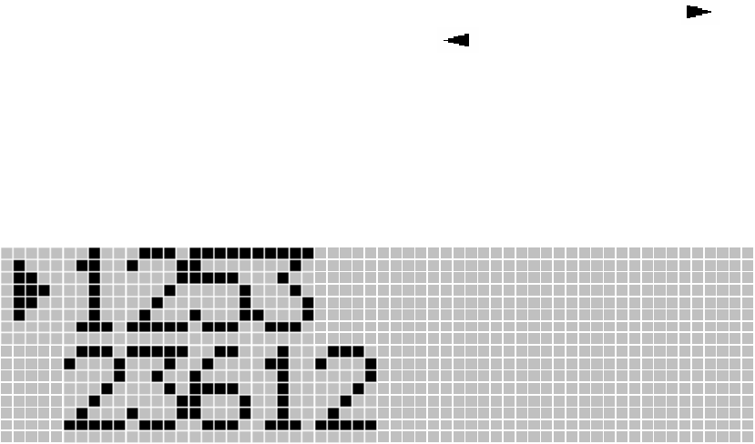
[Display example]
(Arrow icon is always on the 1st line left side)
3.4.3 Dial out redial after OFF HOOK
To recall the last redial entry, just take the line by KEY_HOOK and press KEY_LNR to dial.
3.4.4 Delete a redial buffer :
• Press KEY_CLEAR and “Delete ?” appears.
• Press KEY_OK to make redial number deleted for 1st line data, or press
KEY_MEM/EXIT to cancel the delete operation.
To return to the previous menu, press KEY_MEM/EXIT
3.4.5 Delete all redial buffer :
• Long press KEY_CLEAR and “Delete All ?” appears.
• You can either press KEY_OK again and all redial are deleted, or press
KEY_MEM/EXIT to cancel the delete all operation.
To return to the previous menu, press KEY_MEM/EXIT
18 of 40
3.4.6 Store a Redial list into PHONEBOOK
• Press KEY_OK during display the redial number which you wish to store to the
phonebook. The display show “Add ?”.
• After appearing the “Add ?” And press KEY_OK to confirm. The display show
“Name ?”.
• Enter the name.
• Press KEY_OK after enter the name.
• Press KEY_OK after modify the number.
• Select the melody of your choice (1 to 5) and validate
• Press KEY_OK to confirm.
Remark:
• If the total digit of Re-dial data inside the re-dial buffer is more than Re-dial size
limit, it will only be able to transfer the digits up to Re-dial size limit.
• If the re-dial data size is more than Phonebook size limit, it will only be able to
transfer the digits up to Phonebook limit.
3.5 Internal call transfer
When you wish to transfer an external call to another extension:
• During a call, press KEY_INT
• Select the number of the internal correspondent that you wish to call; the external caller is put
on hold.
• When the internal correspondent picks up, press KEY_HOOK to hang up and transfer the call.
If the internal correspondent does not pick-up, press KEY_INT again to reconnect to the external caller
on line.
3.6 Conference call between two handset and external caller
When you wish to talk an external call and other handset:
• During a call, press KEY_INT
• Select the number of the internal correspondent that you wish to call; the external caller is put
on hold.
• When the internal correspondent picks up, you can talk with internal correspondent first with
external call on hold.
• Press KEY_# to go to Conference call.
• When one of handset press KEY_HOOK or press KEY_INT. Then the conference call is
finished, but other handset still talk with external caller.
If the internal correspondent does not pick-up, press KEY_INT again to reconnect to the external caller
on line.
3.7 Caller ID (CLIP) features
3.7.1 General features
The phone supports CLIP DTMF and FSK type I and II. See 10.1 for more details.
3.7.2 Caller ID display
Note: Caller identification is only available if you have subscribed to this service with your network
operator.
During the incoming alert:
The CLIP information is displayed if they are provided.
Order of display:
19 of 40
• Phonebook name is on the 1st line and calling number is on the 2nd line if the number matches
with the CLIP calling number
• CLIP calling name is on the 1st line and calling number is on the 2nd line if the name data is
transmitted. However, if the number is match with one of phonebook memorized number, it
shall use phonebook memorized name.
• CLIP calling number
• Number matching method is as follows.
- If the one of number which CLIP or phonebook is less than 5 digits, it will not compare.
(If the one of phonebook number is 1234, this number will not use for number
matching)
- If the CLID received 10 digits and phonebook number is 8 digits, CLID last 8 digits will
use for the matching with that phonebook number. And if the CLID is 8 digits and
phonebook number is 10 digits, Phonebook number last 8 digits will use for the
matching with that CLID number.
The following special network messages are managed and displayed at the place of calling number:
Message CLIP type Meanings
WITHHELD FSK type I & II The caller hides its identity
UNAVAILABLE FSK type I & II Network failure, the calling number can’t be transmitted
Special caller texts display format: (Display on the 1st line)
Display CLIP TYPE Caller texts from network
Private FSK type I & II PRIVATE
Unavailable FSK type I & II UNAVAILABLE
International FSK type I & II INTERNATIONAL
Operator FSK type I & II OPERATOR
Payphone FSK type I & II PAYPHONE
Ringback FSK type I & II RINGBACK
Withheld FSK type I & II WITHHELD
Note:
If text data area has above information, the display shall be according to the text data, than
“Parameter name”
The following parameter shall be detected:
Parameter type Parameter Parameter name Display
01h Date and Time Date and Time
02h Calling Line Identify Number
04h 4Fh UNAVAILABLE Unavailable
04h 50h WITHHELD Withheld
06h 4Ch INTERNATIONAL International
07H Calling Party Name Calling Party Name
0Bh 00h Deactivation VMWI
0Bh FFh Activation VMWI
11h 02h RINGBACK Ringback
16h 0Fh PAYPHONE Payphone
Note:
If Date and Time data is not available, it shall store and display the date and time data from handset
inside timer.
The “Withheld” display can be changed to “Private” by EEPROM setting.
The icon will stay during all incoming alert phase and during call if you answer the call.
20 of 40
The call timer display will come again after 15 seconds if no key pressed.
During standby mode:
The icon will flash if un-viewed unanswered CLIP(s) in call list, icon will be off after all
unanswered call is read.
3.7.3 VMWI indication
Refer to the VMWI operation
3.7.4 Recall CLIP list
Unanswered and answered calls are stored in the CLIP list of each handset independently (in
EEPROM).
Note: any new CLIP call will be stored in EEPROM .
Size storage
Each entry will store:
¾ The call number (20 digits)
¾ The caller name (12 digits) if the network send it
¾ The date and hour of the call
Storage sequence
The CLIP information that has been received during incoming alert phase (calling number, name
date/hour) is stored then displayed.
If the new call entries, The icon will flash (480ms ON/OFF) and will off after all new call is read.
Note: The new message indication is reset at power up, so the icon is always off after a reset.
MMI operation
To retrieve the entries:
1. Press KEY_ UP/CLIP or KEY_ DOWN/CLIP to enter the call list. The icon will stay ON
for Unanswered Calls and the icon will stay ON for Answered Calls. If the list is already
empty, then “EMPTY” is displayed on the 1st line
2.
[Display example]
3. Scroll through the calls using the up KEY_UP/CLIP and down KEY_DOWN/CLIP arrows.
4. You will find the different fields of the entry:
21 of 40

If the call is unanswered and un-viewed. The and icon will stay ON. The
will be turned off after it is viewed.
If a matched number found in phonebook memory , the corresponding name will be
shown otherwise if the caller name is available, the caller name will be displayed. If
both are not available, the caller number is displayed on the 1st line.
Press KEY_OK, the first 12 digits of caller number is displayed on the 1st line. If the
number is more than 12 digits, the first 12 digits are displayed with icon. Press
KEY_OK to check the remaining digits with icon.
5. When the CLIP found no matched number in Phone Book and Calling Number is present,
when press KEY_OK again , CLIP data can be stored into phone book ( see 3.7.7)
To select another call list, simply press KEY_UP/CLIP or KEY_DOWN/CLIP . Error tone will be
sounded if reach the top or bottom of the list.
To return to the previous menu, press KEY_MEM/EXIT.
To dial out number just simple press KEY_HOOK
3.7.5 Delete one CLIP list
• Press KEY_CLEAR and “Delete ?” appears.
• There you can either press KEY_OK and CLIP deleted, or presses
KEY_MEM/EXIT to cancel the delete operation.
3.7.6 Delete all CLIP list
• Long press KEY_CLEAR and “Delete All ?” appears.
• There you can either press KEY_OK and all CLID are deleted, or press
KEY_MEM/EXIT to cancel the delete all operation.
To return to the previous menu, press KEY_MEM/EXIT
3.7.7 Store a CLIP list into PHONEBOOK
• After appearing the “Add ?” and press KEY_OK to confirm ( after 3.7.4 step 5 )
• Press KEY_UP/CLIP or KEY_DOWN/CLIP to move the cursor for edit or delete
name. If the CLIP data does not have name, LCD shall display “Name ?”. And
then enter the name.
• Press KEY_OK after modified or enter the name.
• Press KEY_OK after modified number.
• Select the melody of your choice (1 to 5) and validate
• Press KEY_OK to confirm.
3.7.8 Dial out CLIP list
To recall the number from CLIP list, pressing KEY_HOOK will dial out the number.
3.7.9 KPN specification handling
3.7.9.1 DC/AC load activation
• When the unit detect the line reverse, the DC/AC load shall apply within 100mS -
200ms.
• When the unit detect line reverse, the unit need to wait next line reverse. If next
line reverse detect within 80ms, it define that the line reverse is due to ringer
signal.
• If the line reverse is due to ringer signal, the DC/AC load shall not apply
• During ringing stage, if detect ringer off for more than 80ms. The unit shall be
ready for detecting line reverse.
22 of 40

• To detect line reverse, the unit shall detect PSTN line 1 and line 2 both polarity
changing within 10mS. If only one line polarity changing, it should not be polarity
changing. It should be line voltage interruption.
• After finish the call and go to idle stage, the unit shall not detect line reverse for
about 100mS from line releasing point.
• DC load shall be 90Kohm - 110Kohm.
• AC load impedance in the voice band shall be greater than 1800ohm and
preferable lower than 2400ohm.
3.7.9.2 DC/AC load release
• After detect the line reversal, if the unit does not detect the CID DTMF signal
within 1S.
• During receiving the DTMF, if detect the DTMF pause for more than 1 S.
• When received the DTMF ‘C” (Stop code).
• Ringer signal is received.
• OFF HOOK the telephone
3.7.9.3 DTMF signal detection
• A valid DTMF signal > 40mS shall be interpreted as a valid digit.
• A valid DTMF signal < 40mS shall not be interpreted as a valid digit.
• If not valid DTMF signal is present during > 40mS, this shall be interpreted as an
inter digit pause.
• If not valid DTMF signal is present during < 40mS, this shall not be interpreted as
an inter digit pause.
• A level > 37mV shall be recognized as a valid digit.
• A level < 28mV shall not be recognized as a valid digit.
3.8 Phonebook
The phonebook contains up to 50 names of 12 characters max. and numbers of 24 digits. Phonebook
is stored in PP EEPROM. One handset phonebook is independent from other locked handsets.
3.8.1 Dial a number of the phonebook list
To call a correspondent whose name you have saved in the phonebook:
• Press KEY_MEM/EXIT to enter the phonebook. The will be ON.
[Display example]
• Press the first letter of the name; the first name that starts with this letter in the
alphabet appears. For instance to find names beginning by A, press once on
KEY_2, to find names beginning by B, press twice on KEY_2, to find names
beginning by C, press three times on KEY_2
23 of 40

• Go through the list of names with the KEY_UP/CLIP and KEY_DOWN/CLIP
keys the list scrolls up/down in an alphabetical order. If press KEY_DOWN/CLIP,
the 2nd line entry move to 1st line and next entry is displayed on 2nd line.
• Press KEY_MENU/OK to display the number and user can press the
KEY_MENU/OK again to display remaining digits if the recalled phone book
number is more than 12. This is only for 1st line displayed entry.
• Press KEY_MEM/EXIT returns to standby mode
OR
• Press
KEY_HOOK to dial the number of the correspondent whose name is
displayed on the 1st line.
3.8.2 See the dial number of the phonebook list during Talk.
• Press KEY_MEM/EXIT to enter the phonebook. The will be ON.
• Press the first letter of the name; the first name that starts with this letter in the
alphabet appears. For instance to find names beginning by A, press once on
KEY_2, to find names beginning by B, press twice on KEY_2, to find names
beginning by C, press three times on KEY_2
• Go through the list of names with the KEY_UP/CLIP and KEY_DOWN/CLIP
keys the list scrolls up/down in an alphabetical order.
• Press KEY_MENU/OK to display the number and user can press the
KEY_MENU/OK to start dialling or display remaining digits if the recalled phone
book number is more than 12.
• Press KEY_MEM/EXIT to returns to normal Talk mode
3.9 Intercom
3.9.1 Internal call
• Press KEY_INT
• Enter the number of the internal handset (1 or 2)
The and “INT” icons displayed, the number of the internal handset display “INT” with caller
handset number and rings (INT Melody).
Remark: the caller handset go to standby mode if the number of the internal handset is not
available or caller handset.
Before enter the number of internal handset, incoming call applied then go to ring in mode.
3.9.2 End of intercom call
Incoming call applied then go to ring in mode.
The number of the internal handset press KEY_HOOK go to INTERCOM mode
3.9.3 Intercom mode
The and “INT” icons displayed on both handsets.
3.9.4 End of intercom
Any handset (intercom) press KEY_HOOK, go to standby mode.
Incoming call applied then go to ring in mode.
3.10 Page button
24 of 40

Press Page button on the base.
The handsets will ring RING_1 at volume of handset internal ring level setting and display INT with
“□□□□”during 30s unless page key is pressed again on the base or a key is pressed on any locked
handset. (When the handset set to key lock, but it shall be possible to stop the handset paging sound
by pressing any key)
3.11 Battery and charge management
3.11.1 Battery indicator
5 levels indicators icon for mean battery voltage:
> = EEP_BAT_FULL_LEVEL
> = EEP_BAT_HALF3_LEVEL
> = EEP_BAT_HALF2_LEVEL,
Blanking > = EEP_BAT_ALARM_LEVEL
3.11.2 Low battery conditions
If the following conditions are applied:
During a call,
• If mean battery level is less than EEP_BAT_HALF1_LEVEL,
• If battery warning tone option is ON
then a TONE_LOW_BATT will be emitted every minute.
In any state (standby or call), If mean battery level is less than EEP_BAT_ALARM_LEVEL, handset
will enter in power down mode.
3.11.3 Charge conditions
If the following conditions are applied:
• In standby mode,
• If battery warning tone option is ON
• The handset is put on its charger (debounce time: 200 ms)
then a TONE_CONFIRM will be played.
Charging icon:
Scroll for display handset is charging, fast scroll when quick charging mode,
3.11.4 Start-up with low batteries
If battery level at start-up is lower than EEP_BAT_HALF2_LEVEL, the handset will stay in sleep mode
(no LCD, no RF, no MMI working). You need to put the handset into charge until battery level reaches
EEP_HALF2_LEVEL.
25 of 40

3.12 Range indication
3.12.1 Out of range tone
If the following conditions are applied:
• The handset has been out of range since EEP_RANGE_OUT_DELAY s
• If range warning tone option is ON
then a TONE_WARNING will be played.
EEP_RANGE_OUT_DELAY : selected by EEPROM data
3.12.2 In range tone
If a TONE_WARNING has been played, a TONE_IN_RANGE is played when the handset goes into
range the next time.
Note: at start-up, the handset plays the TONE_IN_RANGE only if it goes into range after more than 10
s.
3.12.3 Range limit tone during a call
During a call, in range limit conditions, the handset will play a TONE_WARNING in the Buzzer
The tone is repeated until range conditions are good
If the handset goes out of range, the call is released (on both handset and base).
3.13 Clock and Alarm clock
3.13.1 Clock
The handset has clock indication. The clock data is inside the base unit. So, all the handsets have
same clock indication.
• Update the time by using one of handset.
• The time data is also updated by CLIP data if the CLIP data has time data.
3.14 Alarm activation
When the unit is set to alarm ON and the clock reach to the alarm setting time, the handset shall
generate the alarm sound. And Alarm icon needs to be turned ON on the LCD. Once the clock is
reach to alarm setting time, start to generate the alarm sound. When stop generating alarm sound, the
alarm setting shall be OFF and the icon shall be turned OFF.
3.14.1 During idle
The sound level shall follow the handset internal ring level. However, if the setting is “OFF” the alarm
sound level shall be “Level 1”. During generating the alarm sound, press any key to stop the alarm
without any operation even the handset is “Key Lock” mode. For example, press “KEY_HOOK” to
stop the alarm, however, the handset should not go to talk mode.
If do not press any key for more than one minute, the alarm shall stop automatically.
3.14.2 During Talk
26 of 40
The sound level shall be same as Battery Low warning tone. During generating the alarm sound, press
any key to stop the alarm without any operation.
3.14.3 During ringing or paging
The alarm sound shall not active during paging or ringing.
27 of 40

4 MENU Settings
Menu structure
A wide range of phone settings are accessible through a user friendly menu.
• To enter the menu, press KEY_MENU/OK
• Scroll through the selections using the KEY_UP/CLIP and KEY_DOWN/CLIP keys, the
selections scroll in a loop (you return to the first after the last). To validate a selection, press
KEY_MENU/OK
• To return to the previous menu, press KEY_CLEAR.
• To escape a menu and return to standby mode, press and hold KEY_CLEAR.
• After 15 s without pressing any key, the handset returns in standby mode
Phonebook
A
dd Entr
y
Name ? Number ? Melod
y
1 … 5
Modif
y
Entr
y
Melod
y
1 … 5
Delete Entr
y
Confirm ?
SMS
(Refer to SMS
operation document) (Refer to SMS
operation
document)
MSG Play **** (Refer to DECT 15
operation
document)
TAM Setting **** (Refer to DECT 15
operation
document)
Setu
p
Base Volume Volume off
Volume 1 ... 5
Base Melod
y
Melod
y
1 … 5
Del Handse
t
PIN ? Handset ?
PIN Code PIN ? New PIN
Re-T
yp
e
Dial Mode Tone Dial
Pulse Dial
Recall Recall 1
Recall 2
First Rin
g
ON
OFF
Default PIN ? Confirm ?
Handset Bee
p
Ke
y
Tone ON
OFF
Low Batter
y
ON
OFF
Out of Ran
g
eON
OFF
INT Rin
g
Vol Volume OFF
Volume 1 … 5
EXT Rin
g
Vol Volume OFF
Volume 1 … 5
INT Melod
y
Melod
y
1 … 10
EXT Melod
y
Melod
y
1 … 10
Date and Time Date ? DD / MM
28 of 40
Time ? HH : MM
A
larm Set ON Time ?
OFF
A
uto Answer OFF
ON
Name
Redial Size *** XX (EEPROM setting
1)
YY (EEPROM setting
2
)
**Lan
g
ua
g
e En
g
lish
French
German
Italian
S
p
anish
Nederland
Scandinavian
Hot ke
y
s Hot ke
y
1 XXXXXXXX
Hot ke
y
2 YYYYYYYY
(Display current
setting number)
Ke
y
Lock ?
Re
g
ister Select Base *+ Base 1 2 3 4 New Base X
Auto
Re
g
Base + Base 1 2 3 4 Searchin
g
... PIN ?
Notes : * Only registered base number will be shown.
Notes : + Registered Base Number will blinking
Notes : ** The languages are just example. (Defined by other section)
Notes : *** This menu only appear when the value of EEPROM setting 1 and EEPROM setting 2 are
different.
Notes : **** Those menu for DECT 15. DECT 10 handset shall have ability to be registered to DECT
15 Base. Once register to DECT 15 Base, those menu appear on the menu screen and function as
DECT 15 handset. Refer the DECT 15 MMI document
4.1 PHONEBOOK
• Select "PHONEBOOK"
4.1.1 Add a name
• Select "Add Entry"
• Enter the new name and validate.
• Enter the new telephone number and validate
29 of 40
• It is possible to enter the following data for number entering.
- KET_1 to KEY_0
- KEY_STAR and KEY_#
- KEY_LNR (Pause)
- KEY_R (Recall, Flash)
• Select the melody of your choice (1 to 3) and validate
• Press KEY_OK to confirm.
With your telephone you can write text as well as figures. This is useful for entering a name into the
address book, giving a name to a handset, …
To select a letter, press the corresponding key as many times as is necessary. For example to select
an 1, press 2 once, to select a B, press 2 twice and so on. To select A and then B consecutively,
select a 1, wait until the cursor moves on to the next character, then select a B.
Select Upper case
1 . ,
- ? ! ` @ : ; 1
2 A B C 2 Ä Å Æ
3 D E F 3 É ∆ Φ
4 G H I 4 Γ
5 J K L 5 Λ
6 M N O 6 Ñ Ö Ø Ω
7 P Q R S 7 Π Ψ Σ
8 T U V 8 Ü Θ
9 W X Y Z 9 Ξ
0 (Space) 0
* *
# Change the case
Lower case
1 . ,
- ? ! ` @ : ; 1
2 a b c 2 ä à å æ ç
3 d e f 3 è é
4 g h i 4 ì
5 j k l 5
6 m n o 6 ñ ò ö ø
7 p q r s 7 β
8 t u v 8 ù ü
9 w x y z 9
0 (Space) 0
* *
# Change the case
The following symbols need to be under “0” and “*”
. ( ) & "
\ / _ [ ] $ ¥ £ € % + * =
~ < > # | ^ ¡ ¿ § ¤ { }
30 of 40

4.1.2 Delete a name
• Select "Delete Entry" and then press KEY_OK
• Move through the list of names using the KEY_UP/CLIP and KEY_DOWN/CLIP keys the list
scrolls down in alphabetical order.
• Press KEY_OK when you find the name you wish to delete
• "Confirm ?" appears, press KEY_OK to confirm.
4.1.3 Modify a name or number
• Select "Modify Entry" and then press KEY_OK
• Move through the list of names with the KEY_UP/CLIP and KEY_DOWN/CLIP keys. The list
scrolls down in alphabetical order.
• Press KEY_OK when you find the name to modify
• Press KEY_UP/CLIP or KEY_DOWN/CLIP to move the cursor for edit or delete name.
• Press KEY_OK after modified name.
• Press KEY_CLEAR to delete number.
• Press KEY_OK after modified number.
• Select the melody of your choice (1 to 3) and validate
• Press KEY_OK to confirm.
4.1.4 Change the character case
During entering the name or modifying the name, the user can change the character case by
pressing KEY_#. When enter the name editing menu, the starting character is always upper
case. The character case indication shall be on the Time display as follows.
• Upper case
• Lower case
4.2 SETUP
• Select "Setup"
4.2.1 BASE VOL
This menu enables you to adjust base ring volume
• Select "Base Volume" and validate
• Select the desired volume (Volume OFF or Volume 1 to 5) and validate
4.2.2 BASE MEL
This menu enables you to select base ring melody
• Select "Base Melody" and validate
• Select the melody of your choice (1 to 5) and validate
4.2.3 DEL HS
You can cancel a handset’s association with a base to allow another handset to be associated
• Select "DEL Handset" and validate
• Enter the PIN code and validate
• Select the handset to be cancelled and validate
31 of 40

4.2.4 PIN CODE
The base PIN code is used in subscription operation or to modify some critical parameters in the base.
To change the PIN code:
• Select "PIN code" and validate
• Enter the old 4 figure confidential code and validate
• Enter the new 4 figure confidential code and validate
• Enter the new confidential code a second time and validate
4.2.5 Dial mode selection (This mode will not appear when set the Pulse dialling disable by
EEPROM)
Two types of dialling are available:
1. DTMF tone dialling
2. Pulse dialling
To change the dialling mode:
• Select “Dial Mode” and validate
• Select “Tone” or “Pulse” of dial mode and validate
FTXX_DIAL_MODI : selected by EEPROM data
Note: the Dial mode selection menu can be hidden to lock the base into pulse or DTMF dialling by the
CONFIG_ENA_MENU_DIALMODE flag (see various factory settings).
4.2.6 Recall duration selection
• Select "Recall"
• Choose Recall 1 to select short flash time
• Choose Recall 2 to select long flash time
RECALL 1 & 2 timing: selected by EEPROM data
Note: not recall select function in if Recall 1 & Recall 2 is same timing.
4.2.7 Default settings
This menu enables you to reset both handset and base with default settings.
• Select "Default"
• Enter the base PIN code and validate
• "Confirm ?" appears, press KEY_OK to confirm
Then the handset and base will apply default parameter settings and make a software RESET.
Default parameter Value
Handset name To be advised
Low battery indicator ON
Out of range indicator ON
Key click ON
Auto answer ON
INT melody 1
INT volume 3
EXT melody 1
EXT volume 3
Ear volume 3
Language English
Phonebook Empty
CLID list Empty
Redial list Empty
PIN CODE 0000
PAUSE 3 s
Dial mode DTMF
32 of 40

Key lock OFF
Clock 00:00
Alarm OFF
Date Jan 1st
RPAS enable /disable Enable
Handfree mode speaker volume 3 (Only for DECT 24)
RPAS length setting 400mA
Recall setting Recall 1
Redial size 32
Handset Name Handset
Hot key 1 number XXXXXXXXXX (TBA)
Hot key 2 number XXXXXXXXXX (TBA
Default values in handset and base are defined by EEPROM settings [1]. So they can be adjusted for
each country.
4.3 HANDSET
• Select "Handset"
4.3.1 BEEP
Beep features
The handsets may or may not emit beeps while the keys are pressed , the batteries are low and when
the handset is out of range of the base.
4.3.1.1 KEYTONE
• Select "Key Tone" and validate
• Select “ON” or “OFF” and validate
4.3.1.2 LOW BATTERY
• Select "Low Battery" and validate
• Select “ON” or “OFF” and validate
4.3.1.3 OUTRANGE
• Select "Out Range" and validate
• Select “ON” or “OFF” and validate
4.3.2 INT RING VOL
This menu enables you to adjust handset ring volume (intern melody)
• Select "INT Ring Vol" and validate
• Select the desired volume (Volume OFF or Volume 1 to 5) and validate
4.3.3 EXT RING VOL
This menu enables you to adjust handset ring volume (extern melody)
• Select "EXT Ring Vol" and validate
• Select the desired volume (Volume OFF or Volume 1 to 5) and validate
4.3.4 INT MELODY
This menu enables you to choose a different melody for internal call
• Select "INT Melody" and validate
• Select the melody of your choice (1 to 5) and validate
33 of 40
4.3.5 EXT MELODY
This menu enables you to choose a different melody for external call
• Select "EXT Melody" and validate
• Select the melody of your choice (1 to 5) and validate
4.3.6 DATE AND TIME
There are two menu inside the DATE and TIM. One is to set the date and other is to set the time.
4.3.6.1 Date setting
• Select the DATE ?
• When enter Date setting mode, LCD display current Date with flashing Date
indication. (Display on dots matrix area)
• Enter the Date and Month by the following format.
- The format is DD / MM. If the Date is 5th, it should enter “05”. If the date is 15th, it
should enter “15”
- After enter data, enter the month. If Jan, it should enter 01.
• If the CLIP data has Date data, the Date data shall be updated by CLIP Date data.
• The Date data shall be kept at base unit and when the handset turned on, the
Date data shall be transferred from base to handset.
• If enter wrong data such as 32nd for Date field, it will be error tone and change to
01 on date filed.
4.3.6.2 Time setting
• Time setting should be 24 hour format.
• When enter Time setting mode, LCD display current time with flashing hour
indication. (Display on dots matrix area)
• Enter the current time by 24-hour format and validate. And same time, the update
data send to base to keep for all the handset to have same clock.
• After validate the time, the time indication move to 7-segment time display area.
• If the CLIP data has time data, the clock shall be updated by CLIP time data.
• The time data shall be kept at base unit and when the handset turned on, the time
data shall be transferred from base to handset.
• If enter wrong data such as 25 for Hour field, it will be error tone and change to 01
on hour filed.
4.3.7 ALARM SET
This menu enables you to set the Alarm.
• Select “Alarm Set” and validate.
• Select “ON” or “OFF” by using KEY_UP/DOWN key and validate.
• If select “ON”, the display shows previous setting time with flashing hour indication.
(If no previous data, the display should be 00:00)
• Time setting is same as Clock setting.
• After set the Alarm time, the Alarm icon shall be ON.
4.3.8 AUTO ANSWER
When there is an incoming call and the handset is on the base, the phone automatically takes the line.
• Select "Auto Answer” and validate
• Select "ON" to activate "OFF" to deactivate and validate
4.3.9 NAME
This function allows you to personalise each handset.
• Select "Name" and validate
• Enter the name and validate (max 10 chars)
• During entering the name, the user can select the character case by pressing KEY_LNR
34 of 40

4.3.10 KEY LOCK
This function allows you to lock the key
• Select "Key lock ?” and validate
• Press KEY_MENU/OK to lock key, icon displayed and go to standby mode.
Note: Press KEY_HOOK key can be OFF HOOK during incoming call and Key Lock is on.
4.3.10.1 Quick KEY LOCK
Simply press and hold KEY_STAR/LOCK 3 second
4.3.10.2 To unlock key:
• Press any key “Press *” is displayed, within 5s time out
• Press KEY_STAR/LOCK to unlock key
4.4 REGISTER
• Select "Register" and validate
• Select “Select Base” or “Reg Base” by KEY_UP or KEY_DOWN
• Press KEY_OK to confirm
4.4.1 SELECT BASE
• Select "Select Base" and validate
• “Base 1 2 3 4” is displayed (only the registered base number will be shown and current base
number will be blinking)
• Press 1 - 4 to confirm the selection or KEY_UP/KEY_DOWN + KEY_F to select auto
searching.
• Valid tone is sounded if valid base is found
• “Not Register” is shown and error tone sounded the selection is invalid
4.4.2 REG BASE
• Select "Reg Base" and validate
• “Base 1 2 3 4” is displayed (only the registered base number will be blinking )
• Press 1 - 4 to confirm the selection
• It is now searching the base in subscription mode and “Searching…” is displayed
• Valid tone is sounded and “PIN ?” is shown if valid base found
• Enter subscription PIN code and verified by base
• Valid tone sounded if subscription is successful and back to standby mode.
On the base:
• Put the base into subscription mode, by pressing and holding PAGE_KEY
• The base will then emit a beep, the Line LED will flash. It is now ready to be associated with a
new handset, during the 90 seconds after pressing the button only.
If the handset has located the base, a valid tone is played.
If the handset does not locate the base, it will return to the previous configuration after 1 minute. Try
again by changing the base number and check that you are not in a environment where there is
interference
When a handset is associated with a base, it is given a handset number by the base. It is this number
which is displayed on the handset after the name and must be used for internal calls.
35 of 40

5 Prefix dialling
There are two data for prefix dialling. One is Detect string and other is Replace string. If user enter the
number and first several string match with the pre-programmed string data, then the string will be
replaced by pre-programmed Replace string data. This function can be enabled or disabled by
EEPROM setting. When this function is active, the maximum number of digits for pre-dial is 31 digits.
5.1 Detect string
The pre-programmed detect string is 5 digits inside the EEPROM. The data is 1 to 0 and F (F is for
blank) If the Detect string need to be 003 then the data shall be F,F,0,0,3
5.2 Replace string
The pre-programmed replace string is maximum 10 digits inside the EEPROM. The data is 1 to 0
5.3 Detecting and replacement
The prefix dialling is only working when the dialling is prepared dialling which mean enter the dial
number during idle mode and then OFF HOOK. The product will check the first few digits (maximum 5
digits depended on Detect string data) and if match with detect string, then replace the detected string
to the replace string. If the detect string is all F, there will be no matching and add the replace string to
the dialled number except the dialled number starting from not 1 to 0.
EX 1
Detect string : FFF00
Replace string : 1234567
Dialling number : 00567456
The product will dial ---- 1234567-567456
EX 2
Detect string : FFFFF
Replace string : 1234567
Dialling number : 00567456
The product will dial ---- 1234567-00567456
EX 3
Detect string : FFFFF
Replace string : 1234567
Dialling number : 13567456
The product will dial ---- 1234567-13567456
EX 4
Detect string : FFFFF
Replace string : 1234567
Dialling number : #13567456
The product will dial ---- #13567456
EX 5
Detect string : FFFF0
Replace string : 1234567
Dialling number : 00567456
The product will dial ---- 1234567-0567456
EX 6
Detect string : FFFF0
Replace string : 1234567
Dialling number : 0567456
36 of 40

The product will dial ---- 1234567-567456
EX 7
Detect string : FFF00
Replace string : 1234567
Dialling number : 0567456
The product will dial ---- 0567456
6 DECT 24 addendum (Set the EEPROM setting for DECT 24)
6.1 Change to Handset keypad layout
All keys have the same function as those in the DECT 10 specification
KEY_CLEAR
KEY_HANDSFREE
KEY_CASE
KEY_OK
KEY_MENU
KEY_UP
KEY_LNR
KEY_PAUSE
KEY_MEM
KEY_ESC
KEY_DOWN
KEY_CLIP
KEY_HOOK_OFF
KEY_HOOK_ON
KEY_1
KEY_2
KEY_3
KEY_4
KEY_5
KEY_6
KEY_7
KEY_8
KEY_9
KEY_STAR
KEY_DTMF
KEY_0
KEY_HASH
KEY_R
POWER DOWN
KEY_INT
37 of 40
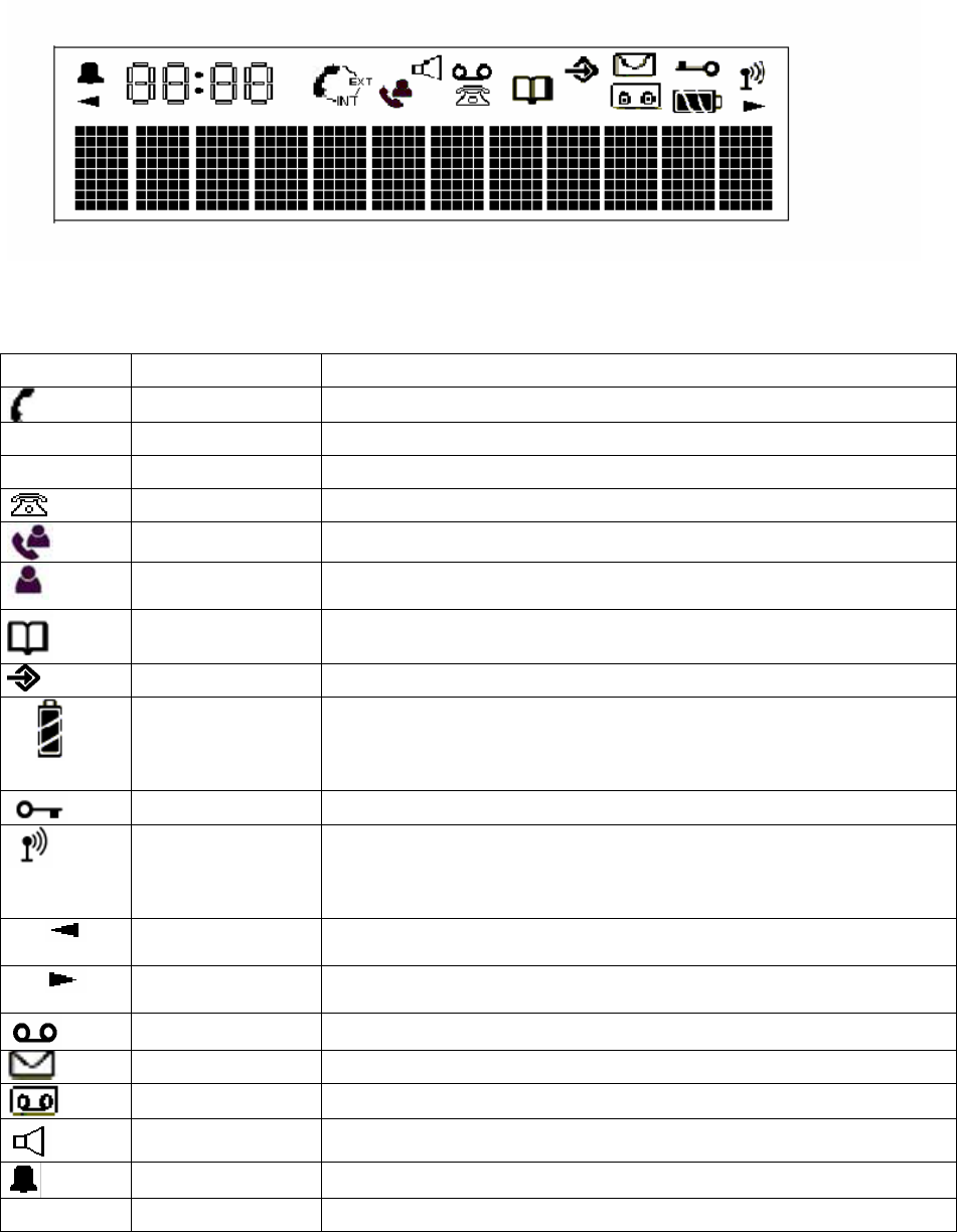
6.1.1 LCD display
The LCD display is composed of 12 characters dots matrix form (8 X 5 matrix), 4 characters 7
segments and 18 icons. (Icon drawings are just reference only. Plesae refere to the LCD specification)
The definition of the icons is as follows:
(Icons are just reference only)
Icon NAME Definition
HOOK_IND Off hook indicator
EXT EXT External call engaged
INT INT Internal call engaged
NEW_CLIP_IND Caller identification available /new numbers in call listing
CLIP_ANSWERED Indicate answered call
CLIP_UNANSWER
ED Indicate unanswered call
PHONEBOOK_IND Phonebook indicator
MENU_IND Menu indicator
BATTERY 3 levels battery indicator
1 segment: weak, 2 segments: medium, 3 segments: full
The segments scroll during battery recharging and stop scrolling
when battery is full
LOCK_IND Handset keypad locked
ANTENNA Signal strength indicator.
The icon is steady when handset is locked to its base
The icon flashes when the handset is unlocked or not subscribed to
any base
LEFT_ARROW Indicates that displayed number or message is longer than the
screen (12 digits)
RIGHT_ARROW Indicates that displayed number or message is longer than the
screen (12 digits)
TAM_MSG VMWI indication
NEW_SMS_IND New SMS message indication
VMWI_IND For the DECT 15
HAND_FREE Hand free indicator
ALARM_SET Alarm set indicator
38 of 40

Pressing the KEY_HANDSFREE from standby mode causes the unit to enter speakerphone mode.
The call is ended by pressing KEY_HOOK_OFF. The user can switch between handsfree and normal
mode by pressing KEY_HANDSFREE.
Pressing UP/Down key to adjust the speaker volume during handfree mode. (5 steps)
The adjusted level shall be kept for next handfree mode.
The setting is only for handfree speaker volume and it shall not effect the earpiece sound level.
When in speakerphone mode the SPEAKER_IND icon shows in the LCD
7 Quick default settings
If you have lost your PIN code, the following procedure allows you to restore default settings on
handset and base.
Press KEY_STAR on handset when power up (insert and remove batteries). The display shows
“DEFAULT”. Press KEY_OK. When the handset locks onto its base, both will restart.
8 Subscribe a new handset
Refer to MENU mode’s REGISTER page
The base can support a maximum of 2 handsets. If you already have 2 handsets, and you wish to
change one of them, you must firstly delete a handset, then associate the new handset.
9 Test modes
9.1 Handset test modes
Refer to document of TEST MODE
9.2 Base unit test modes
Refer to document of TEST MODE
39 of 40
10 Specifications
10.1 CLIP Standards
The phone supports the following CLIP features defined by the identified standard:
Feature Country Standard
FSK type I All applicable EN 300 659-1, EN 300 778-1 and EN 300
659-3
FSK type II EN 300 659-2, EN 300 778-2 and EN 300
659-3
DTMF EN 300 659-1 Annex B, and EN 300 788-1
Annex A
Bellcore standard To be advised
Note : No impedance matching is required except KPN
10.2 DECT Specifications
The phone complies with the following standards
Part Standard
DECT Radio EN301 406
DECT GAP TBR 22
Analogue Telephone
Network TBR 21 and TBR 38
EMC EN301 489-1 and EN301 489-6
Safety EN 60950
40 of 40