Sunwave Communications R205 Booster User Manual Preface
Sunwave Communications Co., Ltd Booster Preface
Contents
- 1. User manual - 1
- 2. User manual - 2
User manual - 2

CrossFire
NP
Installation
Version 1.0

CrossFire iDAS – All-Digital Transport System
User Guide
© SUNWAVE SOLUTIONS LIMITED 2017 2 Version 1.0
Table of Contents
1. Purpose .............................................................................................................................................................................. 3
2. Warnings ............................................................................................................................................................................ 3
3. Site Considerations ............................................................................................................................................................ 4
4. Environmental ................................................................................................................................................................... 4
5. Preparation ........................................................................................................................................................................ 5
5.1. Unpacking and Inspection ................................................................................................................................. 5
5.2. Tools ................................................................................................................................................................... 7
5.3. Antenna ............................................................................................................................................................. 8
5.4. Network Cable ................................................................................................................................................... 9
6. Installation of the AU ....................................................................................................................................................... 10
6.1. Mount the AU in the Rack ............................................................................................................................... 10
6.2. Mount the AU on the Wall ............................................................................................................................... 12
7. Installation of the EU ....................................................................................................................................................... 14
7.1. Mount the EU in the Rack ................................................................................................................................ 14
7.2. Mount the EU on the Wall ............................................................................................................................... 14
8. Installation of the NPRU .................................................................................................................................................. 15
8.1. NPRU Ceiling Installation ................................................................................................................................. 15
8.2. NPRU Roof Wall Installation ............................................................................................................................ 18
9. Antennas Isolation Detector ............................................................................................................................................ 22
CrossFire iDAS – All-Digital Transport System
User Guide
© SUNWAVE SOLUTIONS LIMITED 2017 3 Version 1.0
Purpose
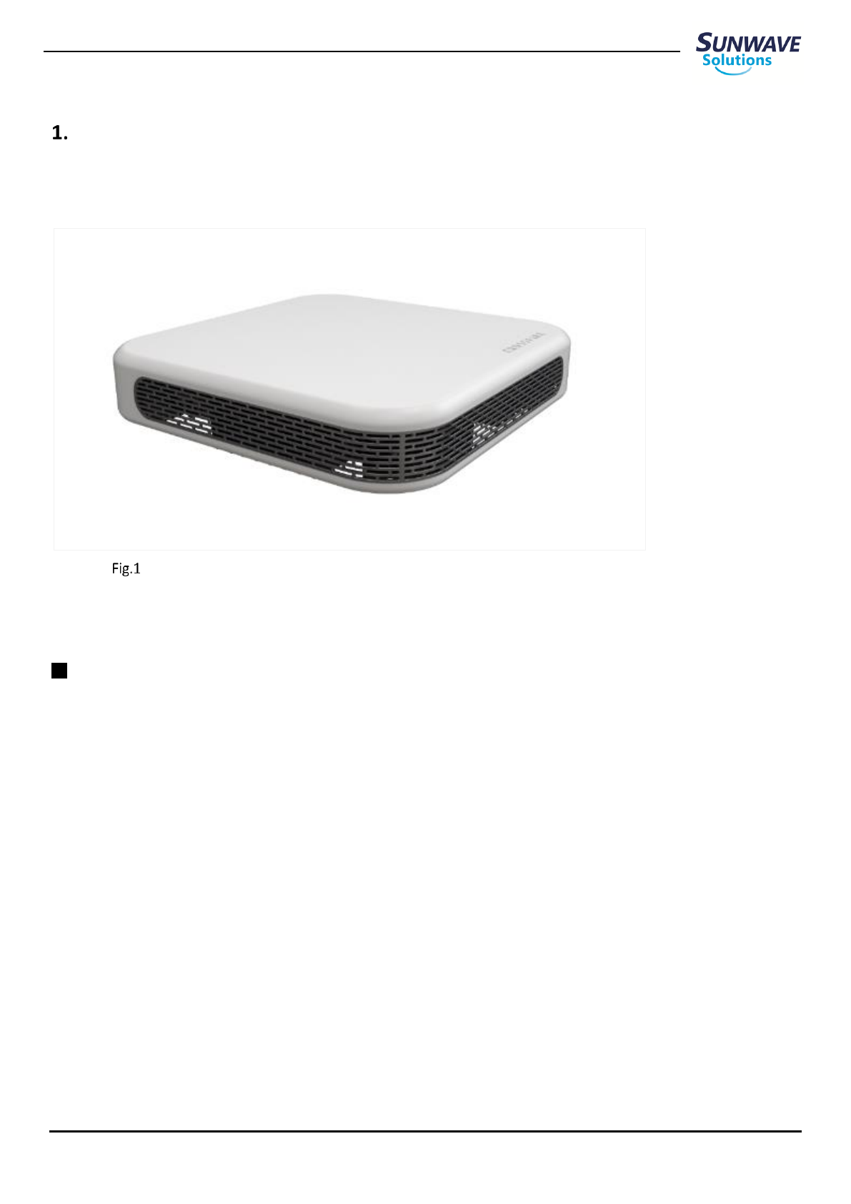
This document describes the installation procedure for CrossFire Nano Power Remote Units.
NPRU Physical Appearance
Warnings
CrossFire is not a consumer product. Please install and use CrossFire in accordance with the instructions.
Before installing or modifying any equipment of CrossFire, the entire instruction should be read and fully understood.
Only qualified personnel are authorized to install and maintain the CrossFire system.
Changes or Modifications not expressly approved by the manufacturer responsible for compliance could void the user’s
authority to operate the equipment.
Follow Electro Static Discharge precautions to avoid any damage of PCB, PSU etc.
Keep equipment powered-off during installing or modifying.
Low pathloss cables connected to antennas are highly recommended.

CrossFire iDAS – All-Digital Transport System
User Guide
© SUNWAVE SOLUTIONS LIMITED 2017 4 Version 1.0
Site Considerations
The distance between the Tx/Rx antennas and the coverage should correspond to LOS (Line of Sight) requirements for
maximum area.
NPRU complies with FCC RF exposure limits for an uncontrolled environment. This equipment must be installed and operated
with a minimum distance of 30 cm between the antennas and any person’s body.
The maximum length between EU-E and NPRU is 100 meters with CAT-6A STP.
The system delay should be taken into consideration when there are neighboring BTS sites overlapping in coverage.
Pick an ideal easy-to-reach location for installation convenience.
radius of space around CrossFire equipment for convenience of maintenance
and on-site inspection.
Install NPRU close to the service area for monitor and debugging.
Environmental
Humidity and temperature have adverse efforts on reliability of the CrossFire system. Therefore, it is highly recommended
to install the equipment in locations with stable humidity, temperature and ventilating.
The equipment has to operate at humidity level and temperature range as follow:
Maximum humidity: 85%
Temperature range: -10 ~ 40℃
Verify that there is a minimum of a 20cm
CrossFire iDAS – All-Digital Transport System
User Guide
© SUNWAVE SOLUTIONS LIMITED 2017 5 Version 1.0
Preparation
5.1. Unpacking and Inspection
Unpack and inspect the packages as the following procedure:
1. Open the shipping packages carefully for each unit from the protective packing sponge.
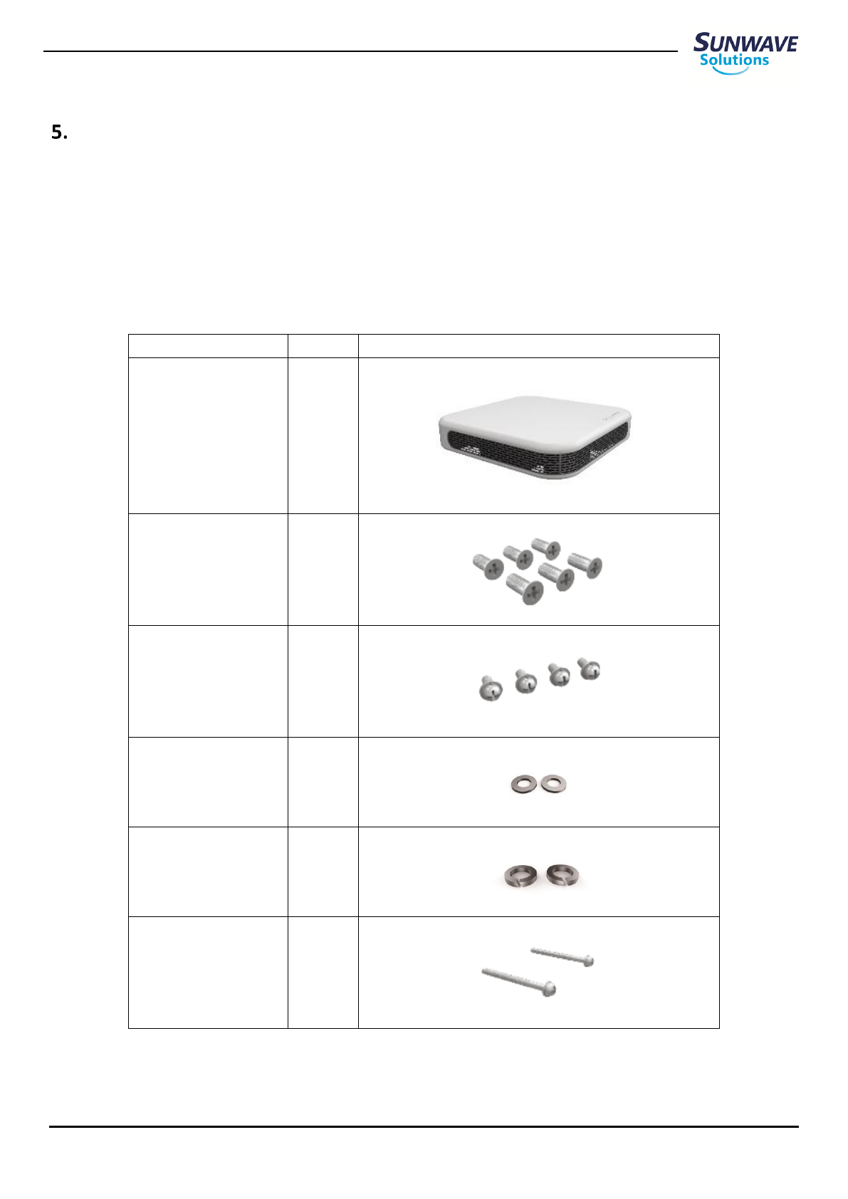
2. Ensure that all equipment and accessories have been delivered (See Table 3-1).
3. Ensure that all equipment and accessories have no damage. If there is any damage, contact your Sunwave service agent.
Description
Quantity
NPRU
1
Screws M3 X 6
6
Screws M4 X 10
4
Flat Washer M6
2
Spring Washer M6
2
Screws M6 X 70
2
CrossFire iDAS – All-Digital Transport System
User Guide
© SUNWAVE SOLUTIONS LIMITED 2017 6 Version 1.0
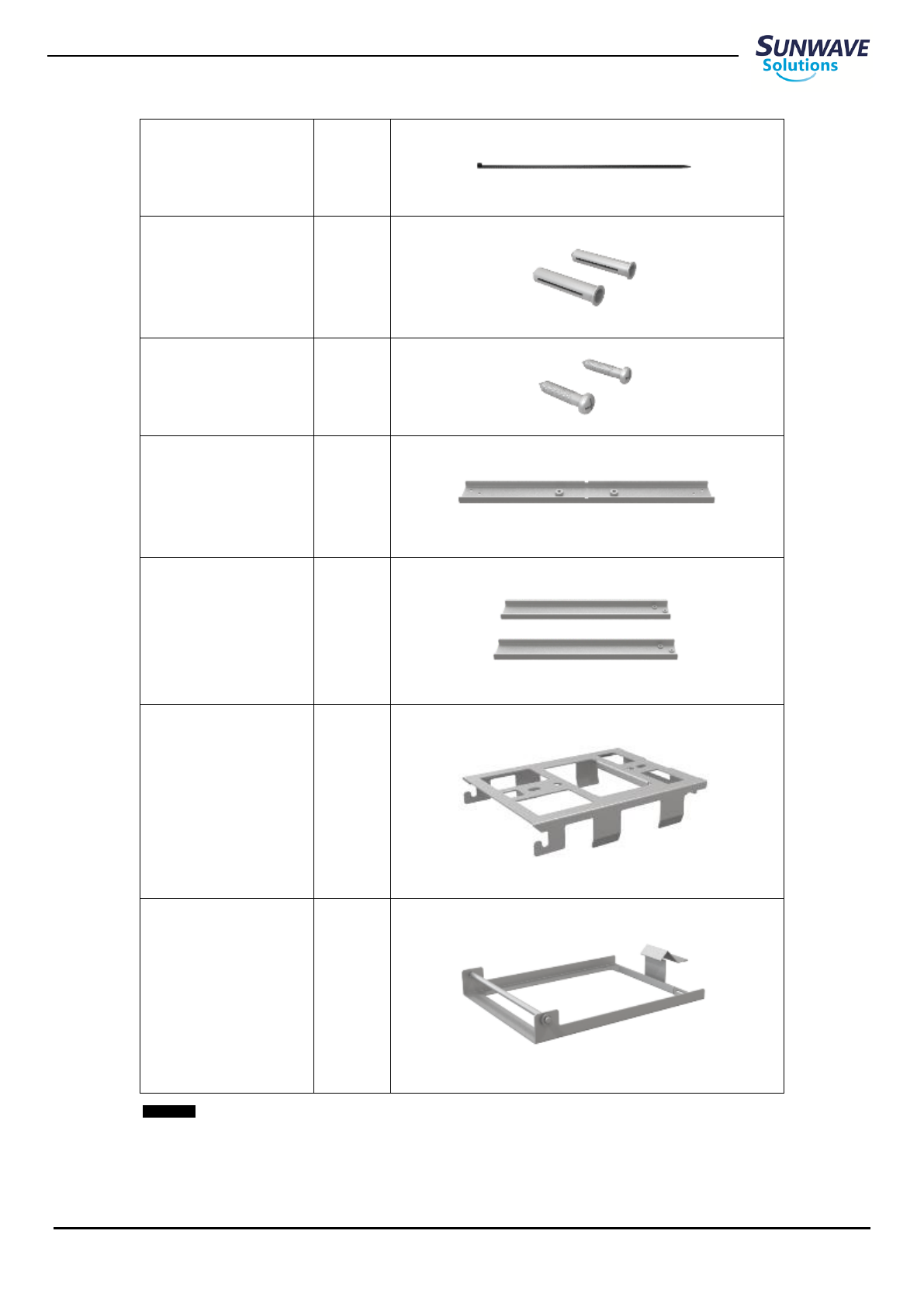
Nylon cable ties
1
Plastic Expansion Nails
2
Screws ST6.3 X 50
2
Mounting Bracket I
1
Mounting Bracket II
2
Mounting Bracket III
1
Mounting Bracket IV
1
Accessories List
CrossFire iDAS – All-Digital Transport System
User Guide
© SUNWAVE SOLUTIONS LIMITED 2017 7 Version 1.0
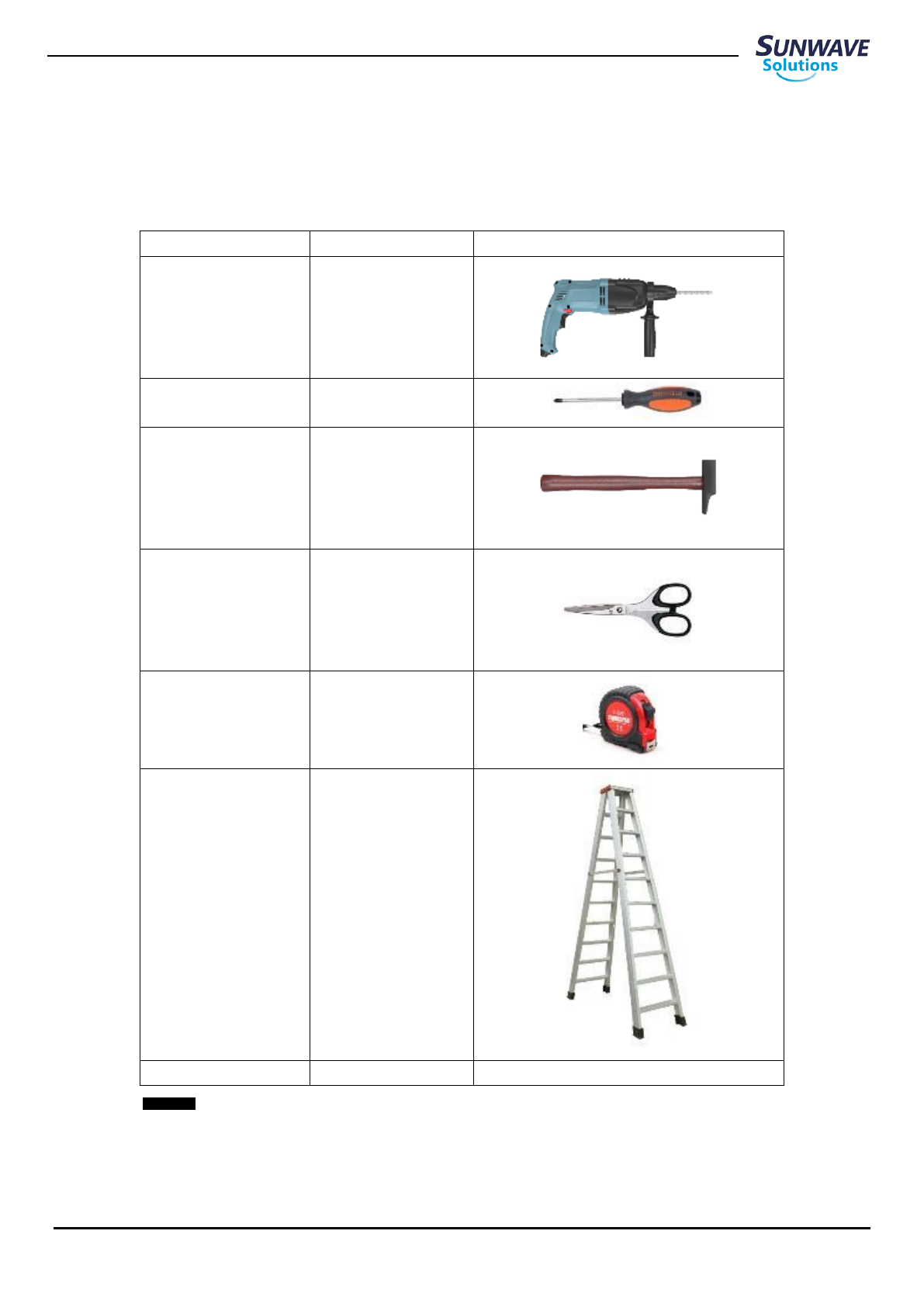
5.2. Tools
Electric drill, cross screw, cutter, ladder and other tools are needed for NPRU installation which are not offered from Sunwave
for now. All of these tools are for customers to prepare (see table 3-2).
Description
Quantity
Electric drill
1
Cross screw
1
Hammer
1
Cutter
1
Flexible ruler
1
Ladder
1
Other tools
/
Tool list

CrossFire iDAS – All-Digital Transport System
User Guide
© SUNWAVE SOLUTIONS LIMITED 2017 8 Version 1.0
5.3. Antenna
According to installation site conditions and coverage requirement, determine proper antenna installation configuration
including distance of Tx and Rx antennas, antennas’ angle and so on.
External antennas – No limitation for available external antennas with respect to requirement as follow:
Directional or Omni Directional
Wideband antennas supporting a range of 700 MHz to 2700 MHz or any single band class between 700 MHz and 2700MHz
Gain: not exceed 4 dBi
Impedance: 50 Ohm
The isolation between Tx and Rx antennas: ≥45 dB
Note: NPRU is capable to support up to 4 frequency bands. Therefore, MIMO (2 antennas – one for Tx port and another one
for Rx port) is highly recommended.
Antenna Installation Guideline
The antennas should be deployed at proper location to avoid unexpected interference and metallic obstruction.
According to coverage requirement, install the antennas at designated height and turn them at appropriate angle to service
area.
The antennas connected to NPRU must be installed protection distance over 30cm for human body safety which should
meet FCC standard.

CrossFire iDAS – All-Digital Transport System
User Guide
© SUNWAVE SOLUTIONS LIMITED 2017 9 Version 1.0
5.4. Network Cable
In the CrossFire system, NPRU is synchronized and POE powered by using network cable to be connect to EU-E at 10GE port.
The maximum length between EU-E and NPRU is 100 meters with CAT-6A STP. STP cables are only specified, while UTP cables
may cause reduced length and performance. The distance is end to end distance and assume the leads are connected to the
EU-E at one end and the NPRU at the other end. The use of patch leads, patch panels or connectors will impact on the
distance.
10GBase-T is sensitively interfered by external noise. Therefore, it must be extremely cautious to handle wiring deployment
and cable tension, bending radius, cable strapping and cable placing management should be under consideration before
installing NPRU.
Cable Strapping
The tightness and density of strapping network cable have an obvious effect on cable performance. Thus the following items
should be taken in consideration for cable wiring:
Use nylon cable ties to bundle up network cables and avoid that network cables shall not be wiring as right angle.
Bundle up network cables in a proper tightness and place the cable bunch on protect sponge.
PSANEXT occurs in a bundle of network cables. The more quantities of cables is, the more PSANEXT arise. The quantities
of cables shall not be over 12 in a bunch.
Cables should be bent at any radius exceeding approximately four times the outside diameter of the cable without any
heavy load.
Marking each cable is a great help for wiring deployment.
CrossFire iDAS – All-Digital Transport System
User Guide
© SUNWAVE SOLUTIONS LIMITED 2017 10 Version 1.0
Installation of the AU
6.1. Mount the AU in the Rack
Attach AU handle
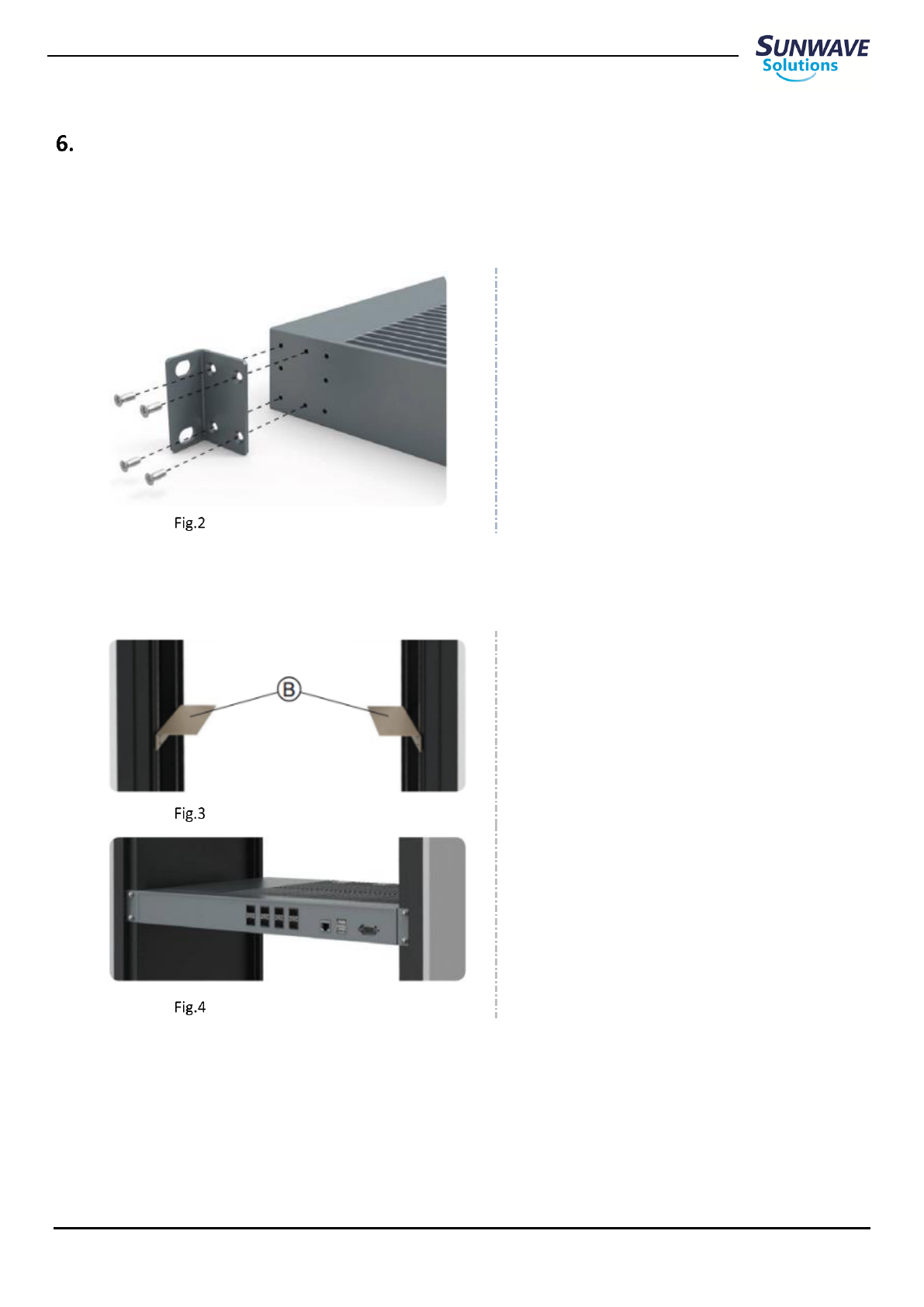
Attaching a 19" Mounting Bracket
1. Attach the 19" mounting brackets at the AU
front, using 4 screws M3×16 per bracket and
the Phillips screwdriver. Observe the
orientation of the brackets (Fig.2).
Attach sliding rails and AU to rack
Attached Sliding Rails
1. Attach the sliding rails Ⓑ to the rack (Fig.3)
Note: the sliding rails is not included in
delivery.
Place AU in Rack
2. Place the AU in the rack (Fig.4)
CrossFire iDAS – All-Digital Transport System
User Guide
© SUNWAVE SOLUTIONS LIMITED 2017 11 Version 1.0
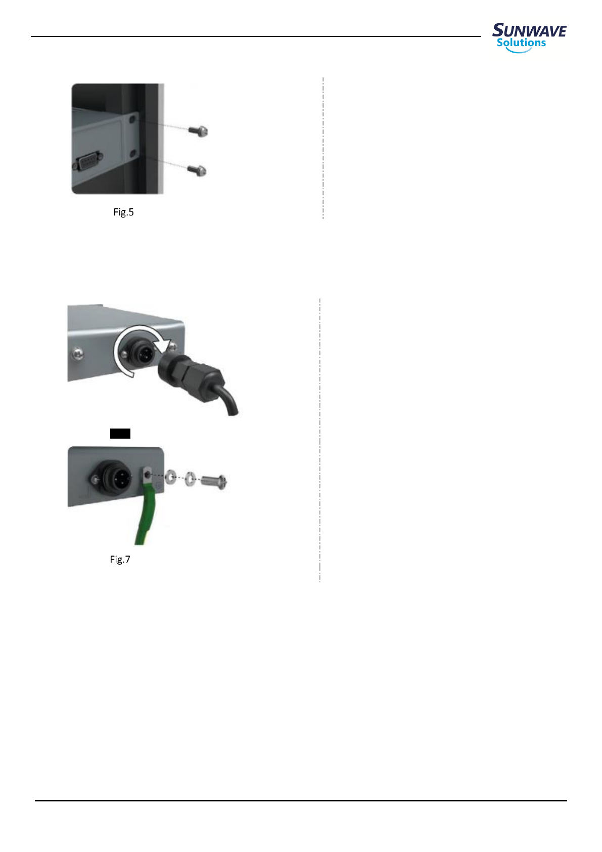
Fix AU with Screws
3. Fix the AU using 2 screws M6×16 on both
side and the Phillips screwdriver (Fig.5).
Note: For rack installation, the separation of adjacent AUs shall be over 3U (1U = 44mm) without fan or
2U with fan occupied in middle.
Connect power and ground cable to AU
Connect Power Cable at Rear Side
1. Connect and lock the power cable at the AU
rear side (Fig.6).
Connect Ground Cable at Rear Side
2. Connect and screw the ground wire at the AU
rear side (Fig.7).
CrossFire iDAS – All-Digital Transport System
User Guide
© SUNWAVE SOLUTIONS LIMITED 2017 13 Version 1.0
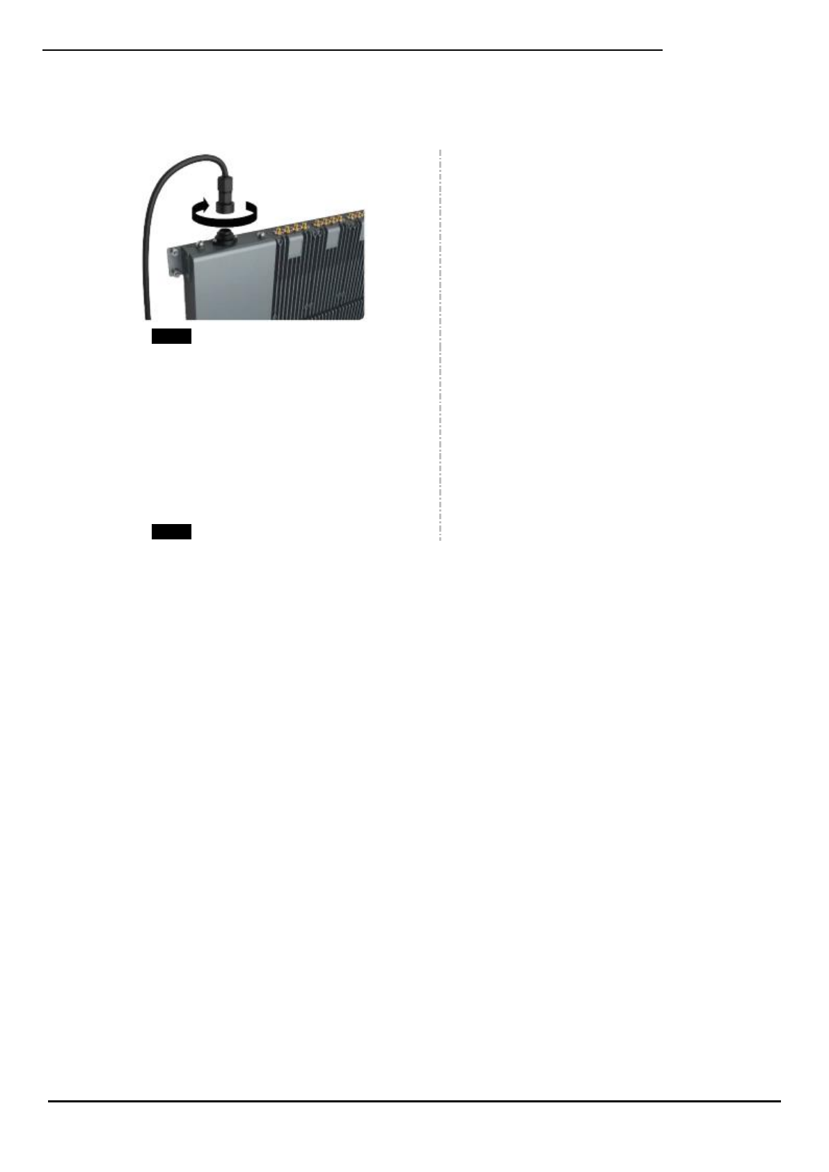
Connect power and ground cable to AU
Connect power cable at rear side
1. Connect and lock the power cable at the AU
rear side; see Fig.11.
Connect ground cable at rear side
2. Connect and screw the ground wire at the AU
rear side; see Fig.12.
CrossFire iDAS – All-Digital Transport System
User Guide
© SUNWAVE SOLUTIONS LIMITED 2017 19 Version 1.0
Drilling Holes Diagram 2
Insert Plastic Expansion Nails
3. Insert plastic expansion nails into holes by
hammer
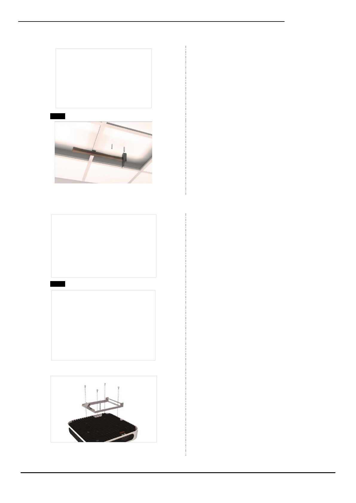
Assemble Mounting Bracket
Assembling Bracket III Diagram 1
Assembling Bracket III Diagram 2
1. Assemble Mounting Bracket III to roof wall
using ST6.3 X 50 screws.
Bracket VI to NPRU top panel 1
2. Assemble Mounting Bracket VI to top
panel of NPRU with 4 X M4 X 10 screws.
CrossFire iDAS – All-Digital Transport System
User Guide
© SUNWAVE SOLUTIONS LIMITED 2017 21 Version 1.0
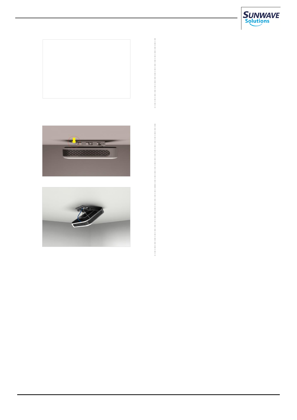
Installation Completed Diagram
6. Buckle the rotary hook side of Mounting
Bracket IV to Mounting Bracket III
Unlock Rotary Hook
Unlock Rotary Hook Diagram 1
1. Press the button of hook at Bracket IV to
expose top panel of NPRU for debugging and
maintenance
Unlock Rotary Hook Diagram 2
CrossFire iDAS – All-Digital Transport System
User Guide
© SUNWAVE SOLUTIONS LIMITED 2017 22 Version 1.0
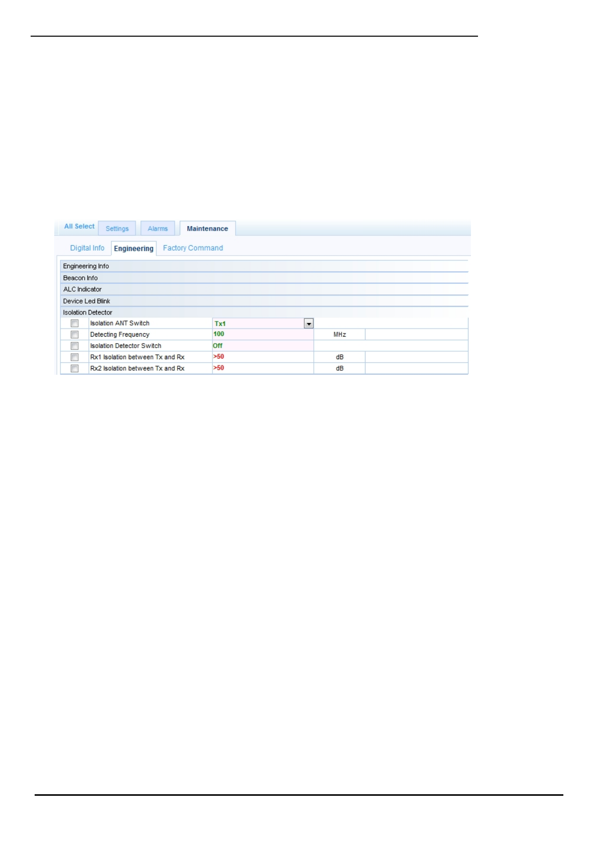
Antennas Isolation Detector
The NPRU provides antennas isolation detector to optimize the antennas deployment to meet the signal coverage
requirement.
Use the following procedures to detect antennas isolation:
1. Log into the NPRU WebOMT. See Crossfire NP User Guide, Chapter 3.2.3 for details.
2. Go to Maintenance > Engineering > Isolation Detector
Isolation Detector
3. Select Tx option in Isolation ANT Switch to choose which antenna transmits RF signal.
4. Enter frequency in Detecting Frequency for testing frequency band.
5. Enable Isolation Detector Switch to start isolation test.
6. Check the Rx1/2 Isolation between Tx and Rx which shall over 45 dB for good performance in MIMO scenario.
Otherwise change the antennas deployment – the distance of Tx/Rx and the antennas’ angle – to meet the requirement.
7. Select another Tx option in Isolation ANT Switch and repeat step 4 to 6.