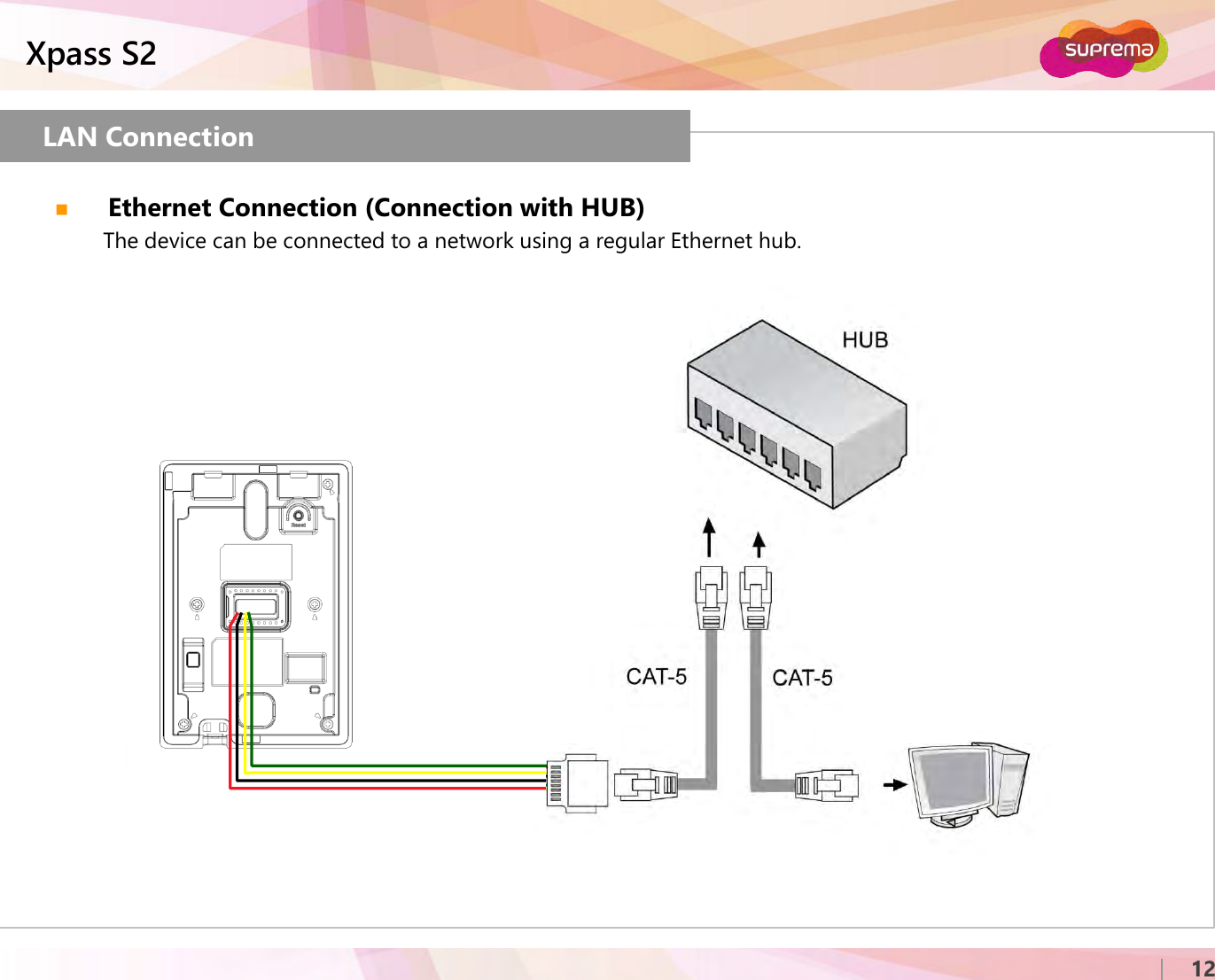
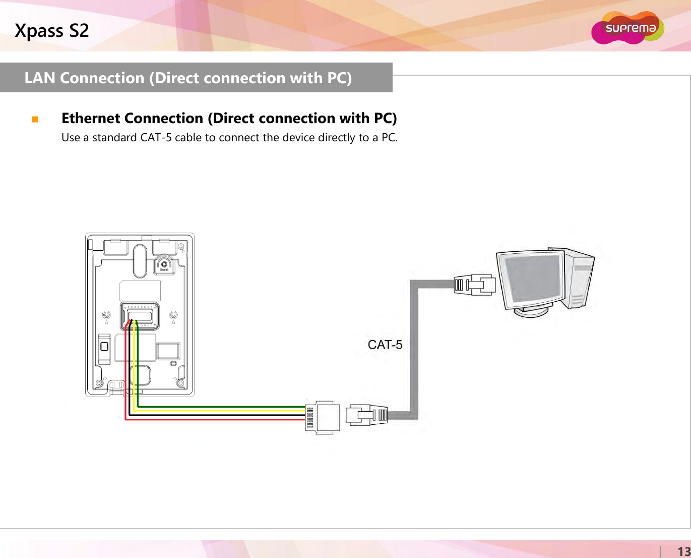
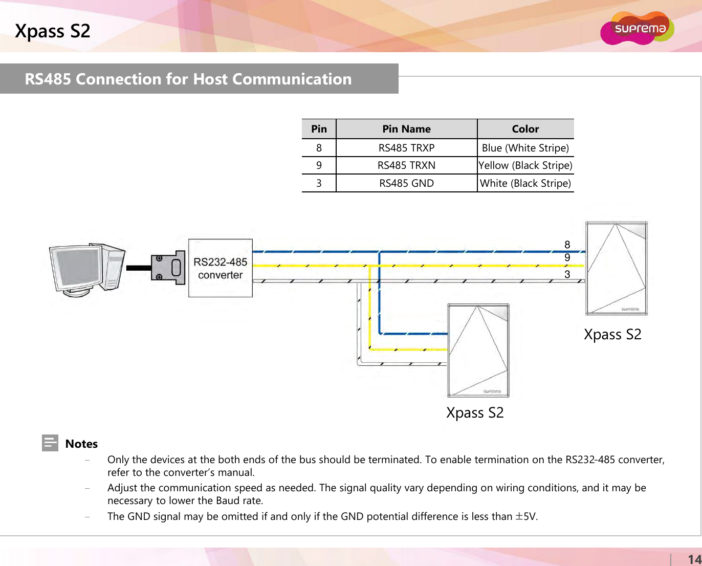
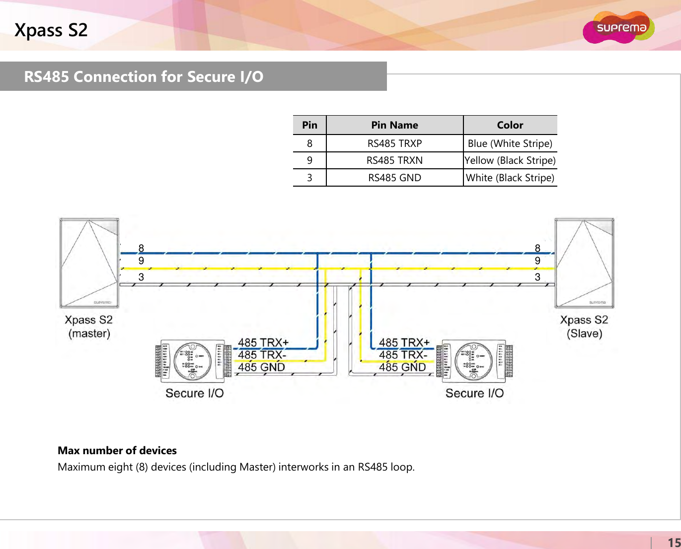
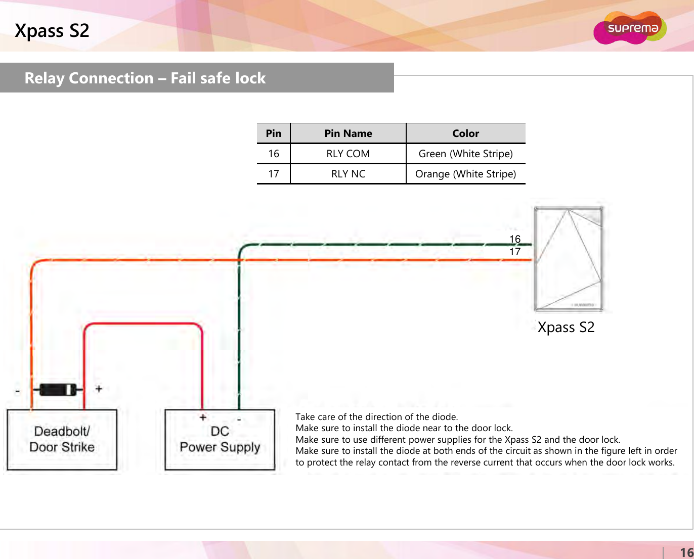
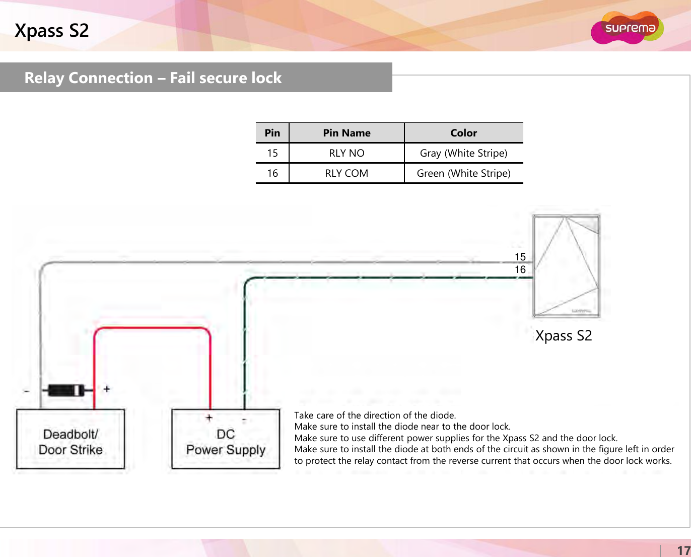
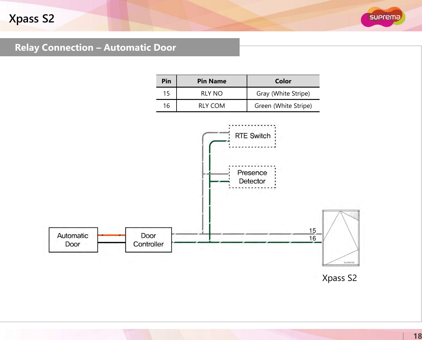
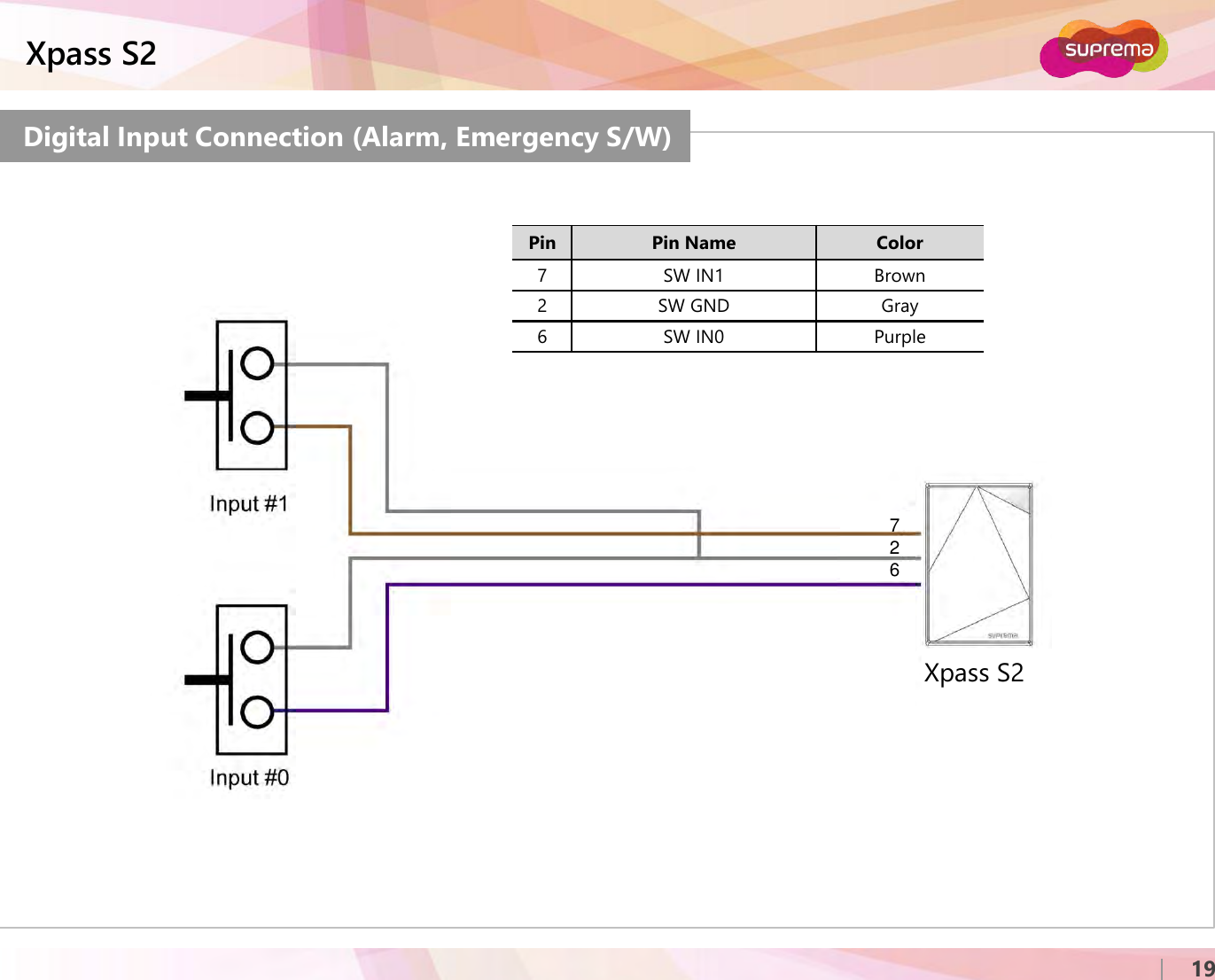
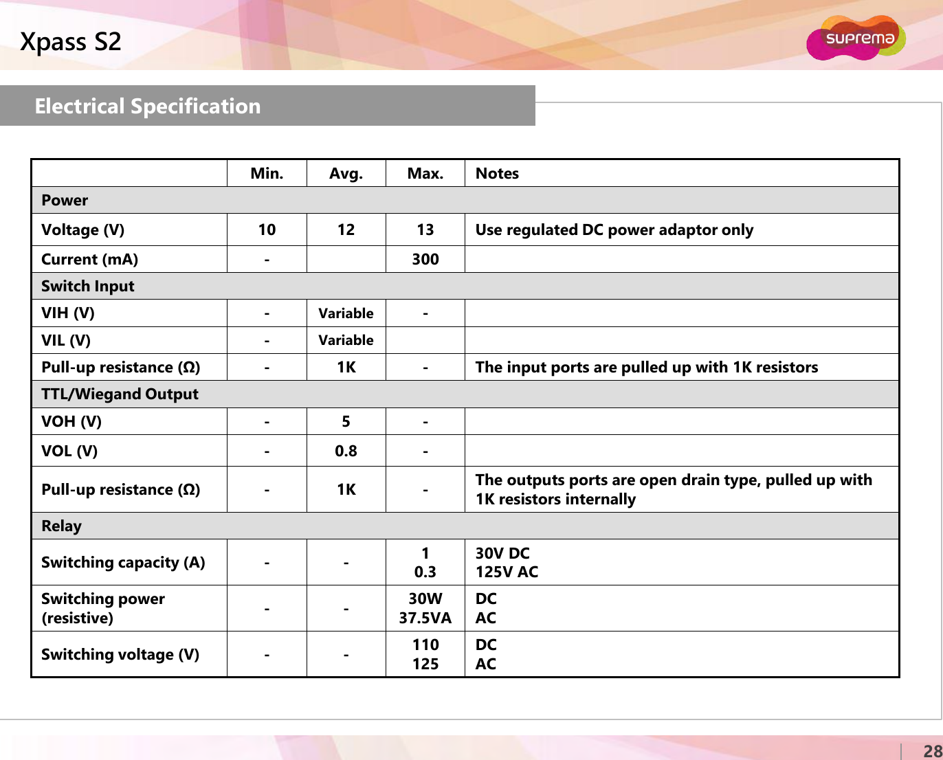
Suprema XPS2M XPASS S2 User Manual Fingerprint Solutions of Suprema

Suprema Inc. XPASS S2 Fingerprint Solutions of Suprema

User Manual

 http://www.emc2000.co.kr FCC TEST REPORT Report No.: EMC-FCC-R0170     EMC compliance Ltd. 65, Sinwon-ro, Yeongtong-gu, Suwon-si, Gyeonggi-do, 443-390, Korea 82-31-336-9919 (Main) 82-505-299-8311 (Fax) This test report shall not be reproduced, except in full, Without the written approval.            User Manual
Xpass S2EN 101.00.XPS2 V1.00www.supremainc.comInstallation GuideIntelligent IP Access Control Reader
ⒸCopyright 2007 Suprema Inc.Xpass S22Important Safety InformationCarefully review the information within the user manual before installing or operating the device.Pay careful attention to the warning and cautions below as they are here to prevent any risk or damage to any person(s) or property associated with the device.WarningFailure to heed these warnings may lead to serious injury or even death!CautionFailure to heed these cautions may lead to minor injury or damage the device.InstallationDo not install the device near heat sources such as radiators, heat registers, and stoves.Do not install the device near areas of large electromagnetic interference.InstallationDo not leave cables (especially power cables) exposed to the outer environment.Do not install the device near objects with a strong magnetic field such as magnets, computer monitors (especially CRT), TV screens and speakers.UsageDo not disassemble, repair or reconstruct the device.Disassembling the device will void the warranty. Only use the device its intended use.Contact your nearest Suprema dealer for technical support.UsageDo not drop or apply any physical shock/impact to the device.Regularly clean the product with a soft dry cloth; avoid benzene or alcohol.
ⒸCopyright 2007 Suprema Inc.Xpass S2‹#›Product ComponentsOptional AccessoriesName of Each PartLED StatusReset Network SettingsProduct DimensionCables and ConnectorsPower ConnectionLAN ConnectionRS485 ConnectionRelay ConnectionDigital Input ConnectionWiegand Input/OutputInstallation of Wall-mount BracketInstallation of Extended BracketInstallation ReferenceSpecificationElectrical SpecificationFCC RulesContents45678910111214161921222324272829
ⒸCopyright 2007 Suprema Inc.Xpass S24Product ComponentsXpass S2 Wall BracketWall Mounting Screws(2 ea)Screw Anchors(2 ea)Shrinkable Tubes Software CDThe components used above may differ depending on the installation environment.Diode(1 ea)Basic Components
ⒸCopyright 2007 Suprema Inc.Xpass S25Optional AccessoriesSecure I/O Plastic StandExtended Bracket 12VDC Adaptor
ⒸCopyright 2007 Suprema Inc.Xpass S26Name of Each Part
ⒸCopyright 2007 Suprema Inc.Xpass S27LED StatusLED Status by ColorColor Sound DescriptionGreen Beep x 3 Authorization SuccessRed Long Beep Authorization FailPink Short Beep On ProcessingFlicker Blue/Skyblue Color per 2 sec N/A NormalFlicker Red/Pink Color per 2 sec N/A LockedFlicker Blue/Red Color per 2 sec N/A Initialized Time due to theInternal Battery DischargeFlicker Blue/Yellow Color per 2 sec N/A IP address is not assigned when terminal is set as Use in theDHCP of TCP/IP settingFor first operation, red LED is blinkingby every 2 seconds. N/A Failed. Please contact to yourdistributor or SupremaFor normal operation, red LED isblinking by every 2 seconds. N/A Security StatusYellow LED is blinking shortly. N/ATerminal is used or received apacket to get IP address whenterminal is set as Use in the Idle status or TCP/IP Setting
ⒸCopyright 2007 Suprema Inc.Xpass S28When you install the Xpass S2 or forget the network setting’s value of Xpass S2 in use, can initial the network setting’s value (TCP/IP address, RS-485 setting) in the switch of Xpass S2’s back side as follows;Reset Network SettingsReset Network Settings1. Press the Resetbutton located on the rear of the Xpass S2 for 3 secondsor more.2. Use the BioStar (Ver. 1.8 or higher) to connect to the XpassS2 using the defaultsettings.Default Network Settings:- IP Address (Static): 192.168.0.1- Use Server: Disabled- RS485: PC Connection, 115200bps3. Enter the desired IP address or RS485 settings and save the new settings.4. Remove the XpassS2 from the device list and reconnect to the device using the new network settings.TCP/IP Status LEDGreen LED blinks shortly: Displaying connection status by TCP/IPRed LED blinks shortly: Displaying data transfer stauts by TCP/IP
ⒸCopyright 2007 Suprema Inc.Xpass S29Product Dimension (unit: mm)< Extended bracket >< Front View > < Wall Bracket >< Side View >
ⒸCopyright 2007 Suprema Inc.Xpass S210Cables and ConnectorsPin Pin Name Description Color1 WGD GND Wiegand Ground2 SW GND Switch Ground3 RS485 GND RS485 Ground4 WGD D0 Wiegand Data 05 WGD D1 Wiegand Data 16 SW IN0 Switch Input 07 SW IN1 Switch Input 18 RS485 TRXP RS485 TRX+9 RS485 TRXN RS485 TRX-Pin Pin Name Description Color10 ETH TXN ETH TXN (LAN)11 ETH TXP ETH TXP (LAN)12 ETH RXN ETH RXN (LAN)13 ETH RXP ETH RXP (LAN)14 PWR GND Power Ground15 RLY NO Relay Normal Open16 RLY COM Relay Common17 RLY NC Relay Normal Close18 PWR IN Power In7151 2 3 4 51617186 8 910 11 12 13 14
ⒸCopyright 2007 Suprema Inc.Xpass S211Power ConnectionPin Pin Name Color18 PWR IN Red14 PWR GND Black (White Stripe)12VDC ±10%, at least 300mA.Comply with standard IEC/EN 60950-1.To share the power with other devices, use a power supply with a higher current rating.Recommended power supplyXpass S21814
ⒸCopyright 2007 Suprema Inc.Xpass S212LAN ConnectionEthernet Connection (Connection with HUB)The device can be connected to a network using a regular Ethernet hub.
ⒸCopyright 2007 Suprema Inc.Xpass S213LAN Connection (Direct connection with PC)Ethernet Connection (Direct connection with PC)Use a standard CAT-5 cable to connect the device directly to a PC.
ⒸCopyright 2007 Suprema Inc.Xpass S214RS485 Connection for Host CommunicationPin Pin Name Color8 RS485 TRXP Blue (White Stripe)9 RS485 TRXN Yellow (Black Stripe)3 RS485 GND White (Black Stripe)Xpass S2Xpass S2Notes−Only the devices at the both ends of the bus should be terminated. To enable termination on the RS232-485 converter, refer to the converter’s manual.−Adjust the communication speed as needed. The signal quality vary depending on wiring conditions, and it may be necessary to lower the Baud rate. −The GND signal may be omitted if and only if the GND potential difference is less than ±5V.893
ⒸCopyright 2007 Suprema Inc.Xpass S215RS485 Connection for Secure I/OPin Pin Name Color8 RS485 TRXP Blue (White Stripe)9 RS485 TRXN Yellow (Black Stripe)3 RS485 GND White (Black Stripe)Max number of devicesMaximum eight (8) devices (including Master) interworks in an RS485 loop.893893
ⒸCopyright 2007 Suprema Inc.Xpass S216Relay Connection –Fail safe lockPin Pin Name Color16 RLY COM Green (White Stripe)17 RLY NC Orange (White Stripe)Xpass S2Take care of the direction of the diode.Make sure to install the diode near to the door lock.Make sure to use different power supplies for the Xpass S2 and the door lock.Make sure to install the diode at both ends of the circuit as shown in the figure left in order to protect the relay contact from the reverse current that occurs when the door lock works.1617
ⒸCopyright 2007 Suprema Inc.Xpass S217Relay Connection –Fail secure lockPin Pin Name Color15 RLY NO Gray (White Stripe)16 RLY COM Green (White Stripe)Take care of the direction of the diode.Make sure to install the diode near to the door lock.Make sure to use different power supplies for the Xpass S2 and the door lock.Make sure to install the diode at both ends of the circuit as shown in the figure left in order to protect the relay contact from the reverse current that occurs when the door lock works.Xpass S21516
ⒸCopyright 2007 Suprema Inc.Xpass S218Relay Connection –Automatic DoorPin Pin Name Color15 RLY NO Gray (White Stripe)16 RLY COM Green (White Stripe)Xpass S21516
ⒸCopyright 2007 Suprema Inc.Xpass S219Digital Input Connection (Alarm, Emergency S/W)Pin Pin Name Color7 SW IN1 Brown2 SW GND Gray6 SW IN0 PurpleXpass S2726
ⒸCopyright 2007 Suprema Inc.Xpass S220Digital Input Connection (RTE, Door Sensor)Pin Pin Name Color7 SW IN1 Brown2 SW GND Gray6 SW IN0 PurpleXpass S2726
ⒸCopyright 2007 Suprema Inc.Xpass S221Wiegand Input/OutputPin Pin Name Color4 WGD D0 Green5 WGD D1 White1 WGD GND BlackPin Pin Name Color4 WGD D0 Green5 WGD D1 White1 WGD GND BlackXpass S2Xpass S2Wiegand InputWiegand Output451451
ⒸCopyright 2007 Suprema Inc.Xpass S222Installation of Wall-mount BracketFix wall mount bracket on a wall using wall mounting screwsHook Xpass S2 on the wall mount bracketFix Xpass S2 to the wall mounting bracket using a wall mounting screw
ⒸCopyright 2007 Suprema Inc.Xpass S223Installation of Extended BracketAssemble the extended bracket using screwsMount the extended bracket to the desired location using screwsFix Xpass S2 and the extended bracket using screwsHook Xpass S2 on the extended bracket
ⒸCopyright 2007 Suprema Inc.Xpass S224Installation Reference 1 - StandaloneXpass S2
ⒸCopyright 2007 Suprema Inc.Xpass S225Installation Reference 2 –Standalone (Secure)Xpass S2
ⒸCopyright 2007 Suprema Inc.Xpass S226Installation Reference 3 –Network
ⒸCopyright 2007 Suprema Inc.Xpass S227SpecificationCPU  32-bit Microprocessor (533Mhz)Memory 16MB Flash + 16MB SDRAMRF Card 13.56MHz ISO14443A/B, ISO15693, Mifare, Desfire (CSN), FelicaUser Capacity 50,000 usersLog Capacity 100,000 eventsInterfaces TCP/IP, RS485, Wiegand In or OutIP Rate IP65 dust and water protectionSound  Multi-tone buzzerLED Multi-color LEDInput & Output Relay x  1Switch input x 2Power 12VDCOperating Temperature -35°C to 65°CDimensions Xpass S2 80 x 120 x 11.4mm (W x H x D)Wall Bracket 68.4 x 110.4mm (W x H)Certificates CE, FCC, MSIP (KCC), IP65, RoHS, REACH, WEEE
ⒸCopyright 2007 Suprema Inc.Xpass S228Electrical SpecificationMin. Avg. Max. NotesPowerVoltage (V) 10 12 13 Use regulated DC power adaptor onlyCurrent (mA) - 300Switch InputVIH (V) - Variable -VIL (V) - VariablePull-up resistance (Ω) -1K - The input ports are pulled up with 1K resistorsTTL/Wiegand OutputVOH (V) - 5 -VOL (V) - 0.8 -Pull-up resistance (Ω) -1K -The outputs ports are open drain type, pulled up with 1K resistors internallyRelaySwitching capacity (A) - - 10.330V DC125V ACSwitching power (resistive) - - 30W37.5VADCACSwitching voltage (V) - - 110125DCAC
ⒸCopyright 2007 Suprema Inc.Xpass S229FCC RulesChanges or modifications not expressly approved by the manufacturer responsible for compliance could void the user’s authority to operate the equipment.This device complies with part 15 of the FCC Rules. Operation is subject to the following two conditions: (1) This device may not cause harmful interface, and (2) this device must accept any interface received, including interference that may cause undesired operation.This equipment has been tested and found to comply with the limit of a Class B digital device, pursuant to Part 15 of the FCC Rules. These limits are designed to provide reasonable protection against harmful interference in a residential installation. This equipment generates, user and can  radiate radio frequency energy and, if not installed and used in accordance with the instructions, may cause harmful interference to radio communications.However, there is no guarantee that interference will not occur in a particular installation; if this equipment does cause harmful interference to radio or television reception, which can be determined by turning the equipment off and on, the user is encouraged to try to correct the interference by one or more the following measures:1. Reorient / Relocate the receiving antenna.2. Increase the separation between the equipment and receiver.3. Connect the equipment into an outlet on a circuit difference from that to which the receiver is connected.4. Consult the dealer or an experienced radio/TV technician for helpCautionWarningInformation to User
㈜슈프리마경기도 성남시 분당구 정자동 파크뷰 오피스타워 16층Tel : 031-783-4510Fax : 031-783-4503온라인고객지원 :  sales@suprema.co.kr회사홈페이지 : www.suprema.co.kr제품홈페이지 : www.biostation.co.krBioEntry Plus의 기능 및 사양은 제품의 품질 향상이나 기능 수정 등으로 인해 예고 없이 변경될 수 있습니다. 제품에 대한 자세한 사항은 ㈜슈프리마로 문의 바랍니다.

Navigation menu