Suprema XPS2M XPASS S2 User Manual Fingerprint Solutions of Suprema
Suprema Inc. XPASS S2 Fingerprint Solutions of Suprema
Suprema >
User Manual
http://www.emc2000.co.kr
FCC TEST REPORT
Report No.: EMC-FCC-R0170
EMC
compliance Ltd.
65, Sinwon-ro, Yeongtong-gu, Suwon-si, Gyeonggi-do, 443-390, Korea
82-31-336-9919 (Main) 82-505-299-8311 (Fax)
This test report shall not be reproduced, except in full, Without the written approval.
User Manual

Xpass S2
EN 101.00.XPS2 V1.00
www.supremainc.com
Installation Guide
Intelligent IP Access Control Reader
ⒸCopyright 2007 Suprema Inc.
Xpass S2
2
Important Safety Information
Carefully review the information within the user manual before installing or operating the device.
Pay careful attention to the warning and cautions below as they are here to prevent any risk or damage
to any person(s) or property associated with the device.
Warning
Failure to heed these warnings may lead to serious
injury or even death!
Caution
Failure to heed these cautions may lead to minor injury
or damage the device.
Installation
Do not install the device near heat sources such as radiators,
heat registers, and stoves.
Do not install the device near areas of large electromagnetic
interference.
Installation
Do not leave cables (especially power cables) exposed to
the outer environment.
Do not install the device near objects with a strong magnetic
field such as magnets, computer monitors (especially CRT),
TV screens and speakers.
Usage
Do not disassemble, repair or reconstruct the device.
Disassembling the device will void the warranty.
Only use the device its intended use.
Contact your nearest Suprema dealer for technical support.
Usage
Do not drop or apply any physical shock/impact to the device.
Regularly clean the product with a soft dry cloth; avoid
benzene or alcohol.

ⒸCopyright 2007 Suprema Inc.
Xpass S2
‹#›
Product Components
Optional Accessories
Name of Each Part
LED Status
Reset Network Settings
Product Dimension
Cables and Connectors
Power Connection
LAN Connection
RS485 Connection
Relay Connection
Digital Input Connection
Wiegand Input/Output
Installation of Wall-mount Bracket
Installation of Extended Bracket
Installation Reference
Specification
Electrical Specification
FCC Rules
Contents
4
5
6
7
8
9
10
11
12
14
16
19
21
22
23
24
27
28
29
ⒸCopyright 2007 Suprema Inc.
Xpass S2
4
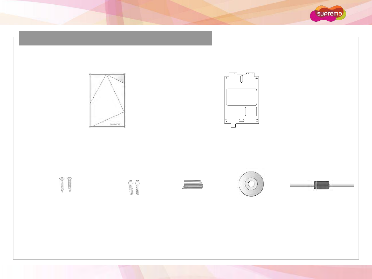
Product Components
Xpass S2 Wall Bracket
Wall Mounting Screws
(2 ea)
Screw Anchors
(2 ea)
Shrinkable Tubes Software CD
The components used above may differ depending on the installation environment.
Diode
(1 ea)
Basic Components
ⒸCopyright 2007 Suprema Inc.
Xpass S2
5
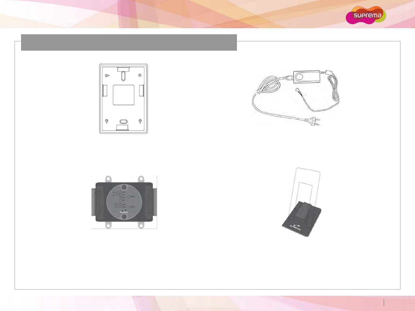
Optional Accessories
Secure I/O Plastic Stand
Extended Bracket 12VDC Adaptor
ⒸCopyright 2007 Suprema Inc.
Xpass S2
6
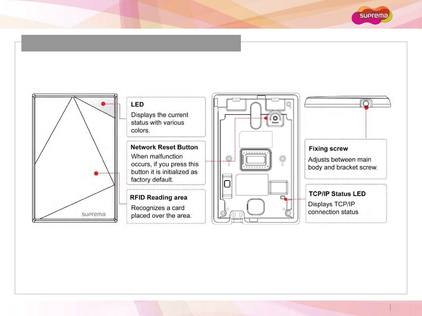
Name of Each Part
ⒸCopyright 2007 Suprema Inc.
Xpass S2
7
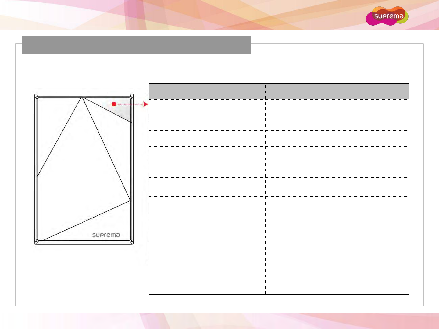
LED Status
LED Status by Color
Color Sound Description
Green Beep x 3 Authorization Success
Red Long Beep Authorization Fail
Pink Short Beep On Processing
Flicker Blue/Skyblue Color per 2 sec N/A Normal
Flicker Red/Pink Color per 2 sec N/A Locked
Flicker Blue/Red Color per 2 sec N/A Initialized Time due to the
Internal Battery Discharge
Flicker Blue/Yellow Color per 2 sec N/A IP address is not assigned when
terminal is set as Use in the
DHCP of TCP/IP setting
For first operation, red LED is blinking
by every 2 seconds. N/A Failed. Please contact to your
distributor or Suprema
For normal operation, red LED is
blinking by every 2 seconds. N/A Security Status
Yellow LED is blinking shortly. N/A
Terminal is used or received a
packet to get IP address when
terminal is set as Use in the Idle
status or TCP/IP Setting
ⒸCopyright 2007 Suprema Inc.
Xpass S2
8
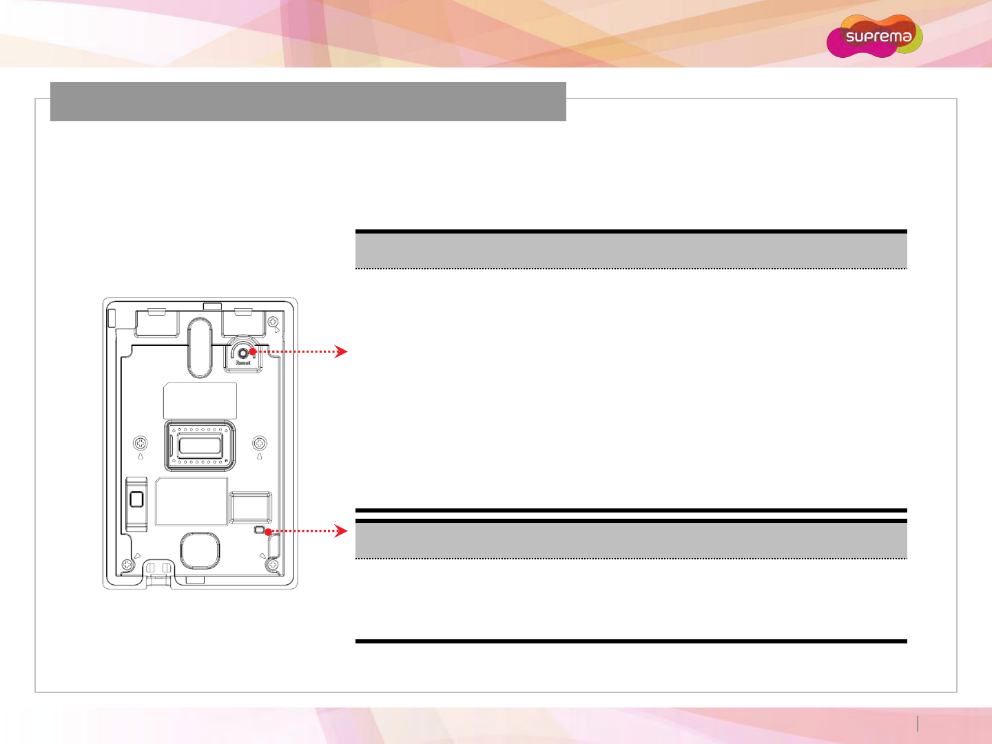
When you install the Xpass S2 or forget the network setting’s value of Xpass S2 in use, can initial the
network setting’s value (TCP/IP address, RS-485 setting) in the switch of Xpass S2’s back side as follows;
Reset Network Settings
Reset Network Settings
1. Press the Resetbutton located on the rear of the Xpass S2 for 3 secondsor more.
2. Use the BioStar (Ver. 1.8 or higher) to connect to the XpassS2 using the default
settings.
Default Network Settings:
- IP Address (Static): 192.168.0.1
- Use Server: Disabled
- RS485: PC Connection, 115200bps
3. Enter the desired IP address or RS485 settings and save the new settings.
4. Remove the XpassS2 from the device list and reconnect to the device using the new network
settings.
TCP/IP Status LED
Green LED blinks shortly: Displaying connection status by TCP/IP
Red LED blinks shortly: Displaying data transfer stauts by TCP/IP
ⒸCopyright 2007 Suprema Inc.
Xpass S2
9
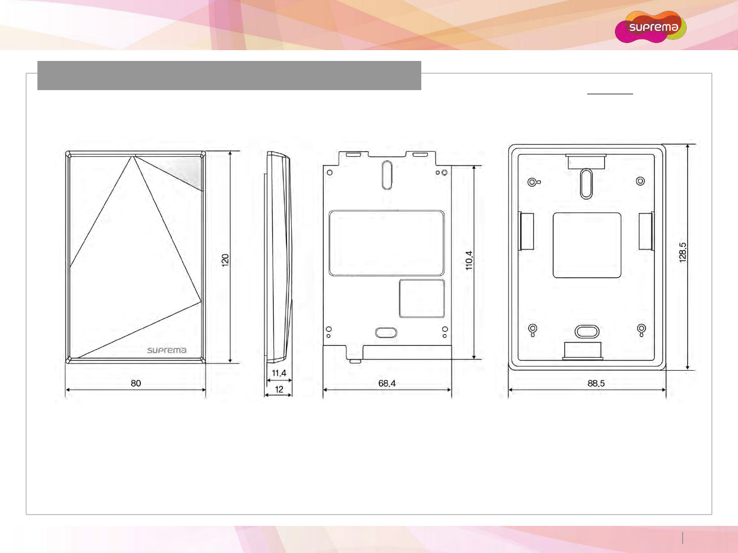
Product Dimension (unit: mm)
< Extended bracket >< Front View > < Wall Bracket >< Side View >
ⒸCopyright 2007 Suprema Inc.
Xpass S2
10
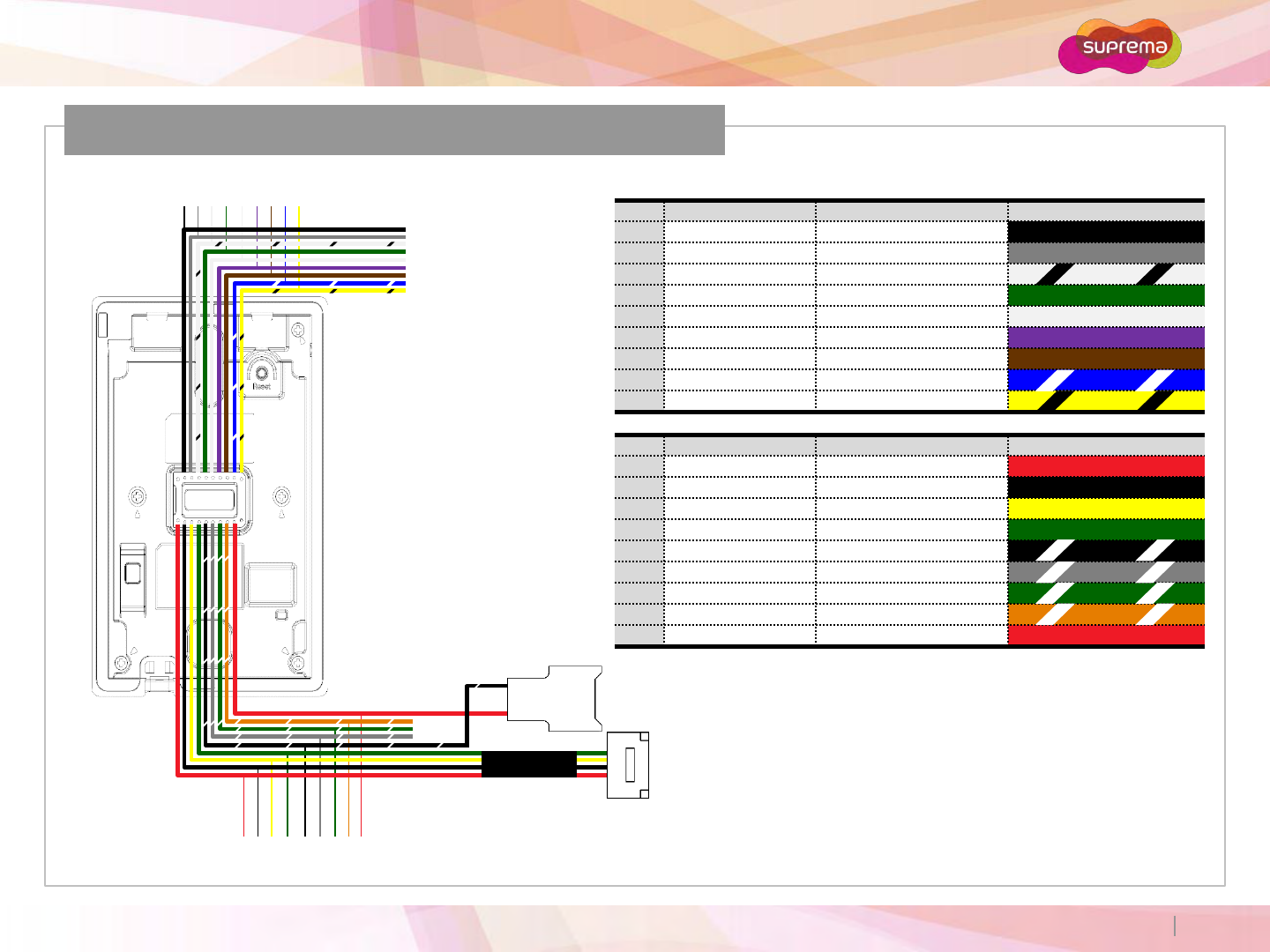
Cables and Connectors
Pin Pin Name Description Color
1 WGD GND Wiegand Ground
2 SW GND Switch Ground
3 RS485 GND RS485 Ground
4 WGD D0 Wiegand Data 0
5 WGD D1 Wiegand Data 1
6 SW IN0 Switch Input 0
7 SW IN1 Switch Input 1
8 RS485 TRXP RS485 TRX+
9 RS485 TRXN RS485 TRX-
Pin Pin Name Description Color
10 ETH TXN ETH TXN (LAN)
11 ETH TXP ETH TXP (LAN)
12 ETH RXN ETH RXN (LAN)
13 ETH RXP ETH RXP (LAN)
14 PWR GND Power Ground
15 RLY NO Relay Normal Open
16 RLY COM Relay Common
17 RLY NC Relay Normal Close
18 PWR IN Power In
7
15
1 2 3 4 5
161718
6 8 9
10 11 12 13 14
ⒸCopyright 2007 Suprema Inc.
Xpass S2
11
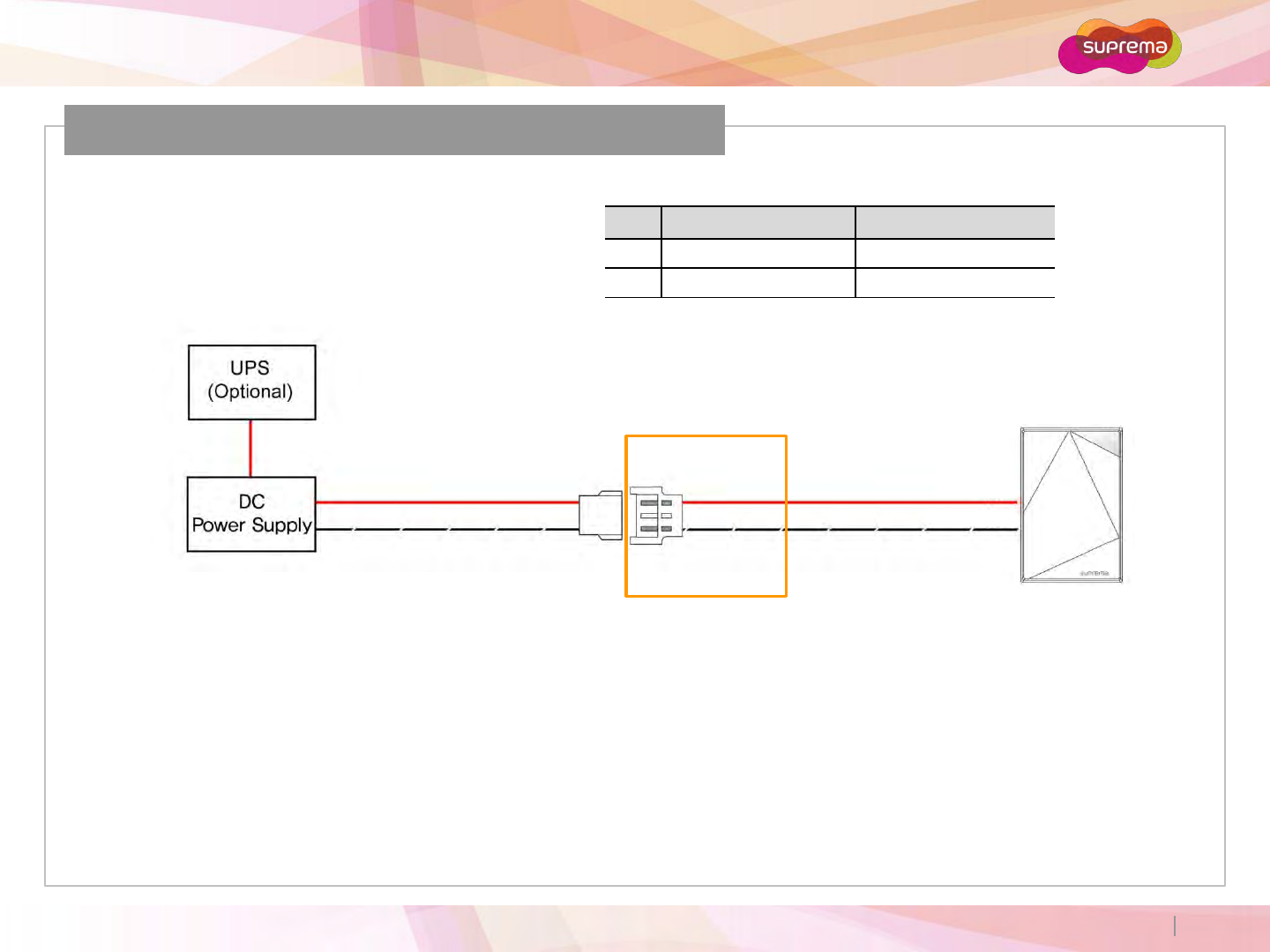
Power Connection
Pin Pin Name Color
18 PWR IN Red
14 PWR GND Black (White Stripe)
12VDC ±10%, at least 300mA.
Comply with standard IEC/EN 60950-1.
To share the power with other devices, use a power supply with a higher current rating.
Recommended power supply
Xpass S2
18
14
ⒸCopyright 2007 Suprema Inc.
Xpass S2
12
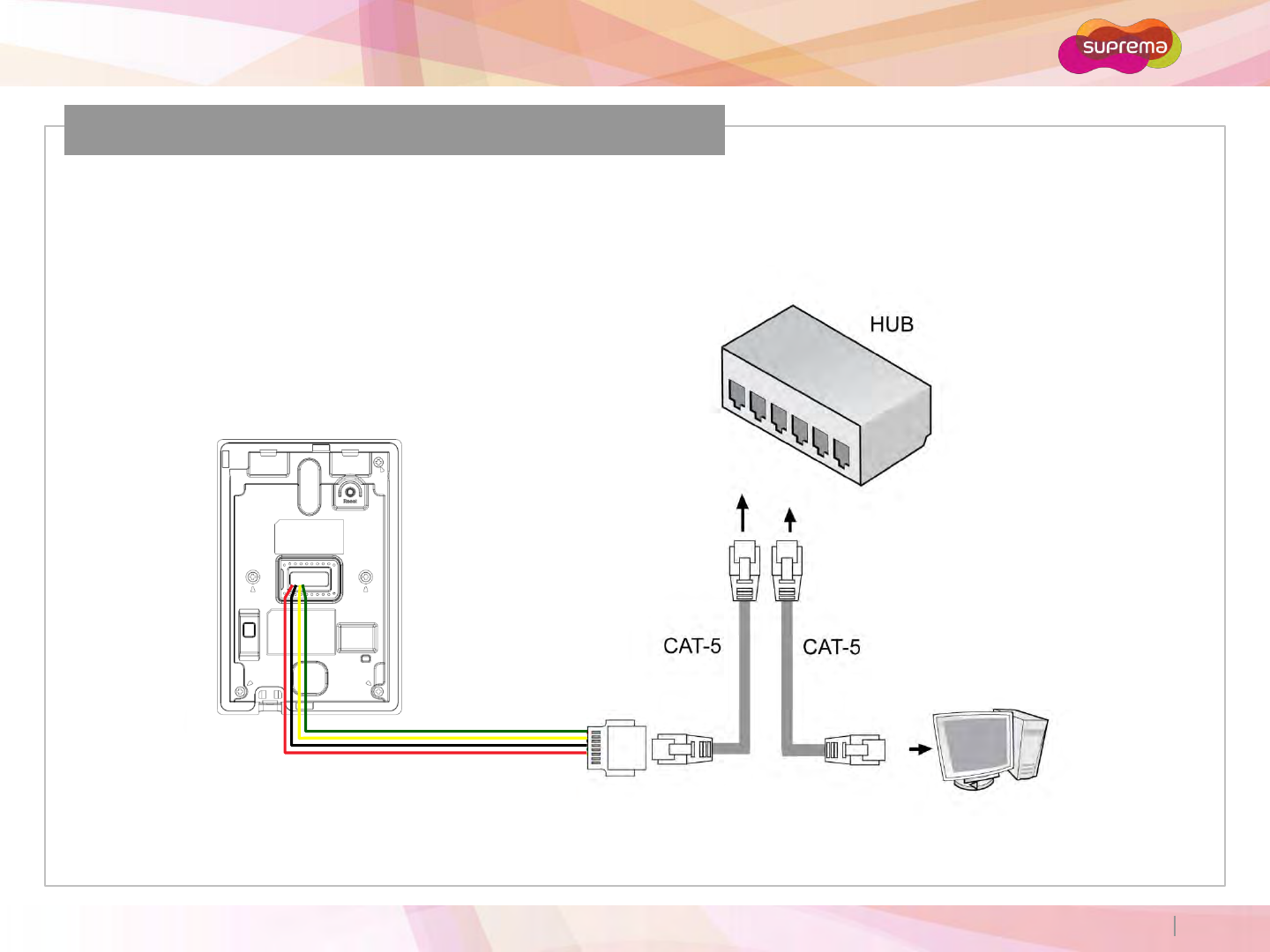
LAN Connection
Ethernet Connection (Connection with HUB)
The device can be connected to a network using a regular Ethernet hub.
ⒸCopyright 2007 Suprema Inc.
Xpass S2
13
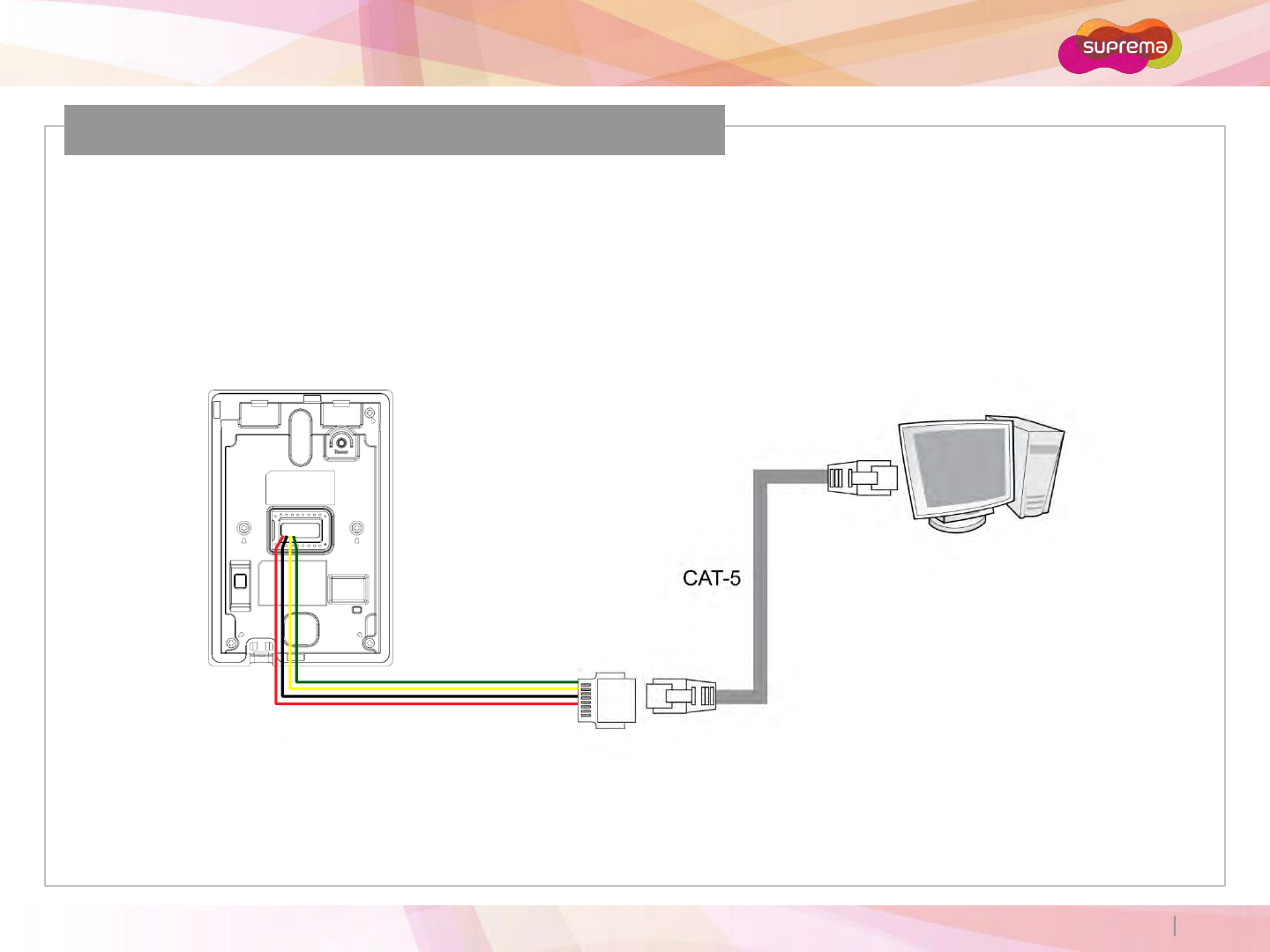
LAN Connection (Direct connection with PC)
Ethernet Connection (Direct connection with PC)
Use a standard CAT-5 cable to connect the device directly to a PC.
ⒸCopyright 2007 Suprema Inc.
Xpass S2
14
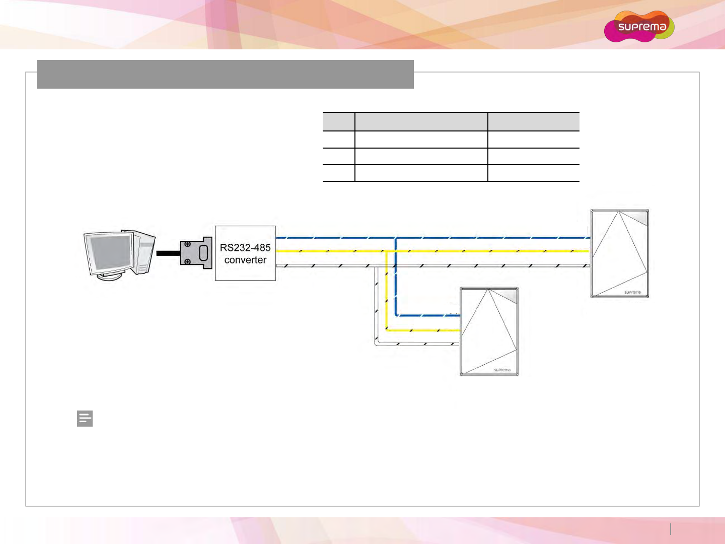
RS485 Connection for Host Communication
Pin Pin Name Color
8 RS485 TRXP Blue (White Stripe)
9 RS485 TRXN Yellow (Black Stripe)
3 RS485 GND White (Black Stripe)
Xpass S2
Xpass S2
Notes
−Only the devices at the both ends of the bus should be terminated. To enable termination on the RS232-485 converter,
refer to the converter’s manual.
−Adjust the communication speed as needed. The signal quality vary depending on wiring conditions, and it may be
necessary to lower the Baud rate.
−The GND signal may be omitted if and only if the GND potential difference is less than ±5V.
8
9
3
ⒸCopyright 2007 Suprema Inc.
Xpass S2
15
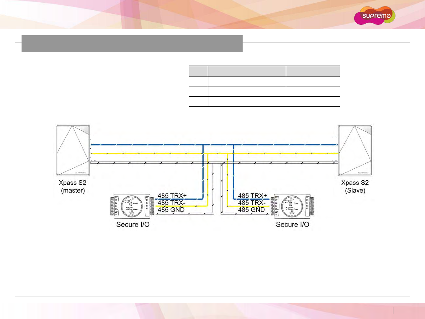
RS485 Connection for Secure I/O
Pin Pin Name Color
8 RS485 TRXP Blue (White Stripe)
9 RS485 TRXN Yellow (Black Stripe)
3 RS485 GND White (Black Stripe)
Max number of devices
Maximum eight (8) devices (including Master) interworks in an RS485 loop.
8
9
3
8
9
3
ⒸCopyright 2007 Suprema Inc.
Xpass S2
16
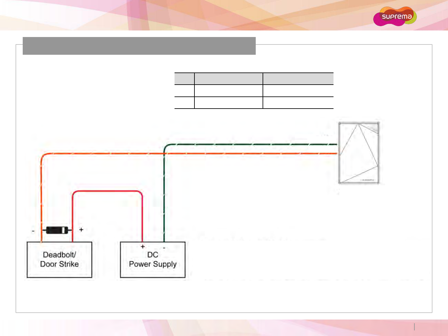
Relay Connection –Fail safe lock
Pin Pin Name Color
16 RLY COM Green (White Stripe)
17 RLY NC Orange (White Stripe)
Xpass S2
Take care of the direction of the diode.
Make sure to install the diode near to the door lock.
Make sure to use different power supplies for the Xpass S2 and the door lock.
Make sure to install the diode at both ends of the circuit as shown in the figure left in order
to protect the relay contact from the reverse current that occurs when the door lock works.
16
17
ⒸCopyright 2007 Suprema Inc.
Xpass S2
17
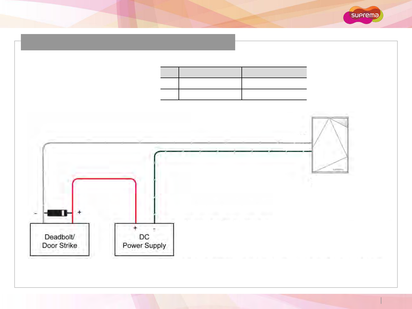
Relay Connection –Fail secure lock
Pin Pin Name Color
15 RLY NO Gray (White Stripe)
16 RLY COM Green (White Stripe)
Take care of the direction of the diode.
Make sure to install the diode near to the door lock.
Make sure to use different power supplies for the Xpass S2 and the door lock.
Make sure to install the diode at both ends of the circuit as shown in the figure left in order
to protect the relay contact from the reverse current that occurs when the door lock works.
Xpass S2
15
16
ⒸCopyright 2007 Suprema Inc.
Xpass S2
18
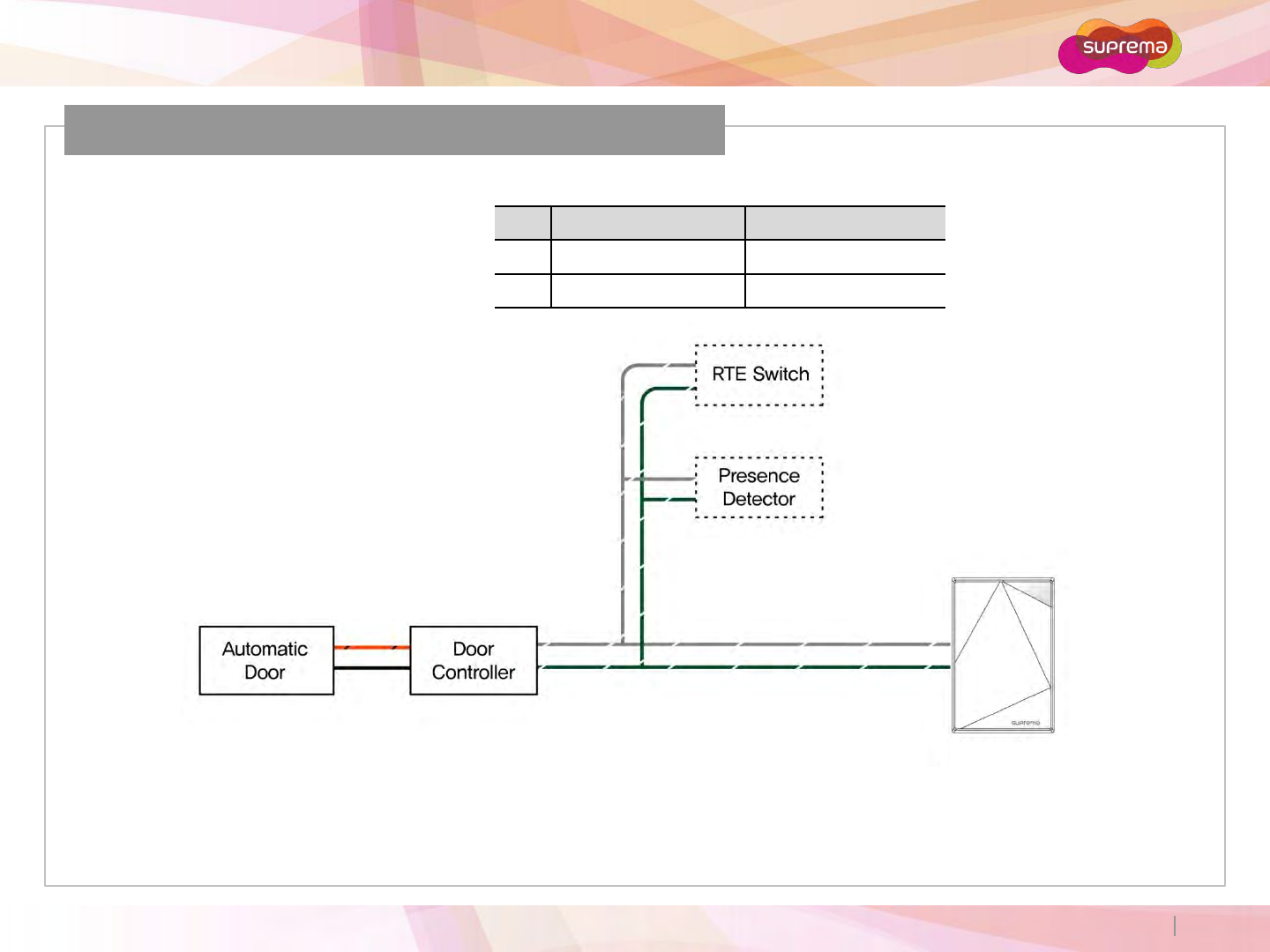
Relay Connection –Automatic Door
Pin Pin Name Color
15 RLY NO Gray (White Stripe)
16 RLY COM Green (White Stripe)
Xpass S2
15
16
ⒸCopyright 2007 Suprema Inc.
Xpass S2
19
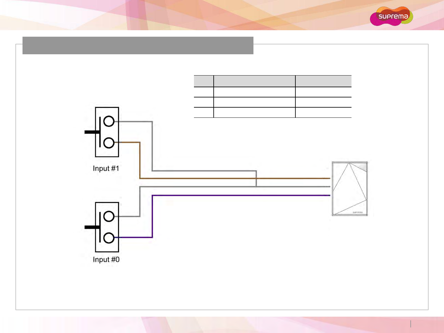
Digital Input Connection (Alarm, Emergency S/W)
Pin Pin Name Color
7 SW IN1 Brown
2 SW GND Gray
6 SW IN0 Purple
Xpass S2
7
2
6
ⒸCopyright 2007 Suprema Inc.
Xpass S2
20
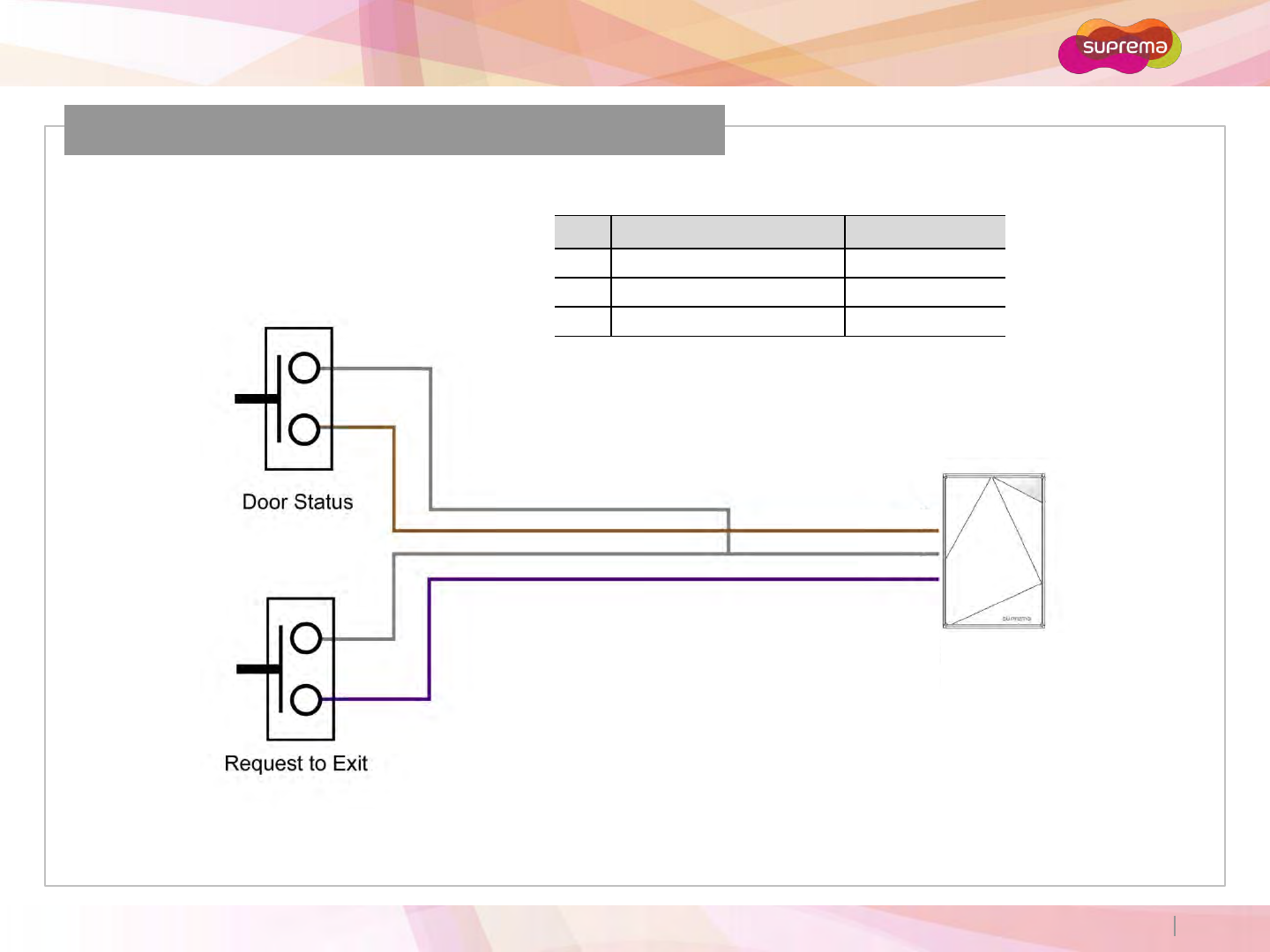
Digital Input Connection (RTE, Door Sensor)
Pin Pin Name Color
7 SW IN1 Brown
2 SW GND Gray
6 SW IN0 Purple
Xpass S2
7
2
6
ⒸCopyright 2007 Suprema Inc.
Xpass S2
21
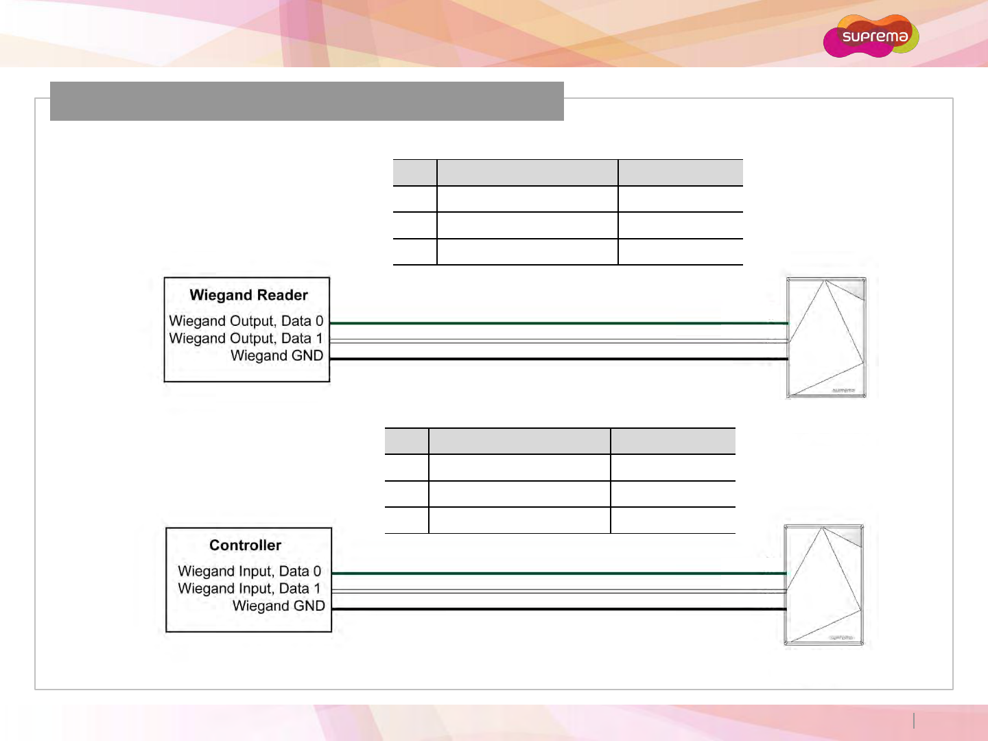
Wiegand Input/Output
Pin Pin Name Color
4 WGD D0 Green
5 WGD D1 White
1 WGD GND Black
Pin Pin Name Color
4 WGD D0 Green
5 WGD D1 White
1 WGD GND Black
Xpass S2
Xpass S2
Wiegand Input
Wiegand Output
4
5
1
4
5
1
ⒸCopyright 2007 Suprema Inc.
Xpass S2
22
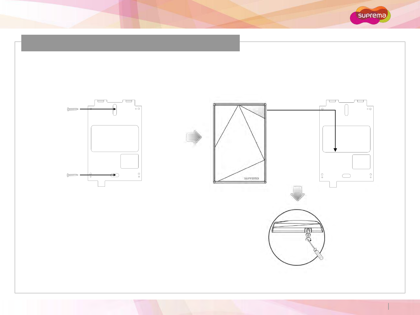
Installation of Wall-mount Bracket
Fix wall mount bracket on a wall
using wall mounting screws
Hook Xpass S2 on the wall mount bracket
Fix Xpass S2 to the wall mounting bracket
using a wall mounting screw
ⒸCopyright 2007 Suprema Inc.
Xpass S2
23
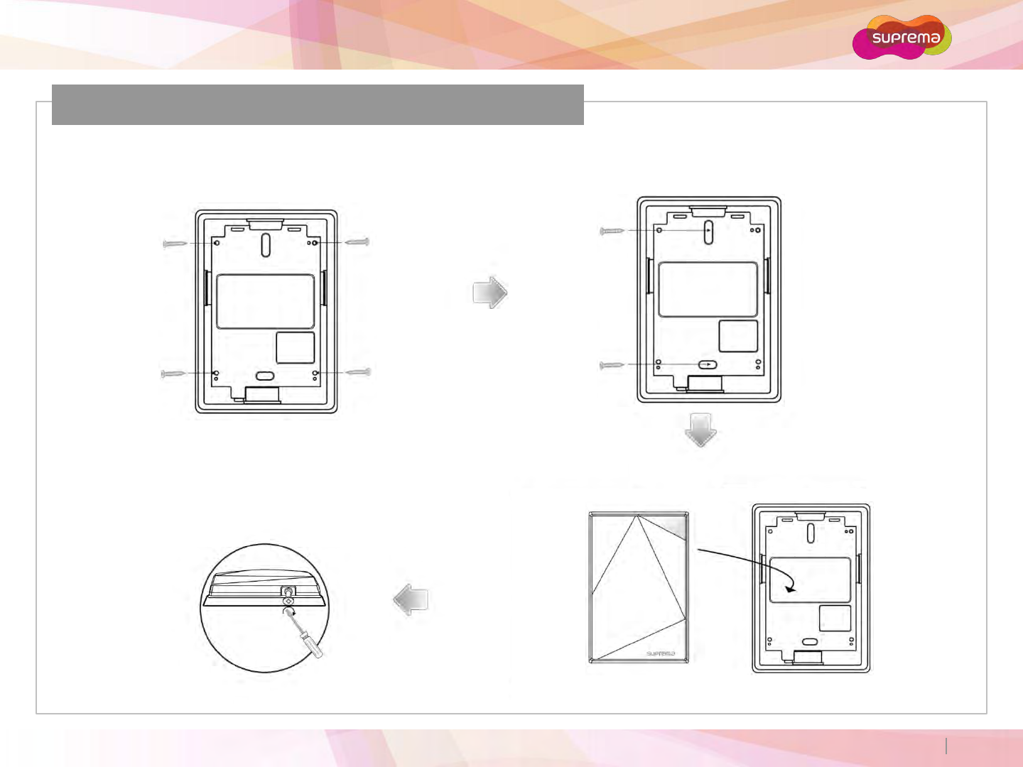
Installation of Extended Bracket
Assemble the extended bracket
using screws
Mount the extended bracket to the
desired location using screws
Fix Xpass S2 and the extended
bracket using screws
Hook Xpass S2 on the extended bracket
ⒸCopyright 2007 Suprema Inc.
Xpass S2
24
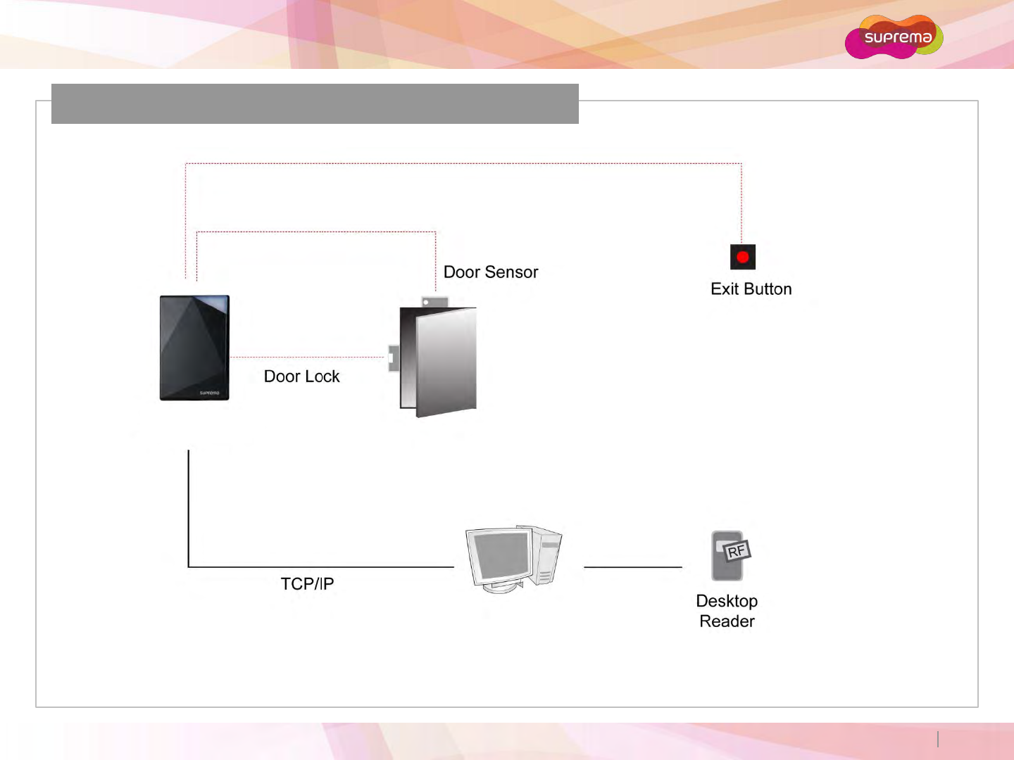
Installation Reference 1 - Standalone
Xpass S2
ⒸCopyright 2007 Suprema Inc.
Xpass S2
25
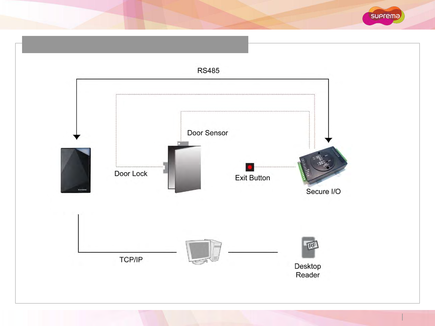
Installation Reference 2 –Standalone (Secure)
Xpass S2
ⒸCopyright 2007 Suprema Inc.
Xpass S2
26
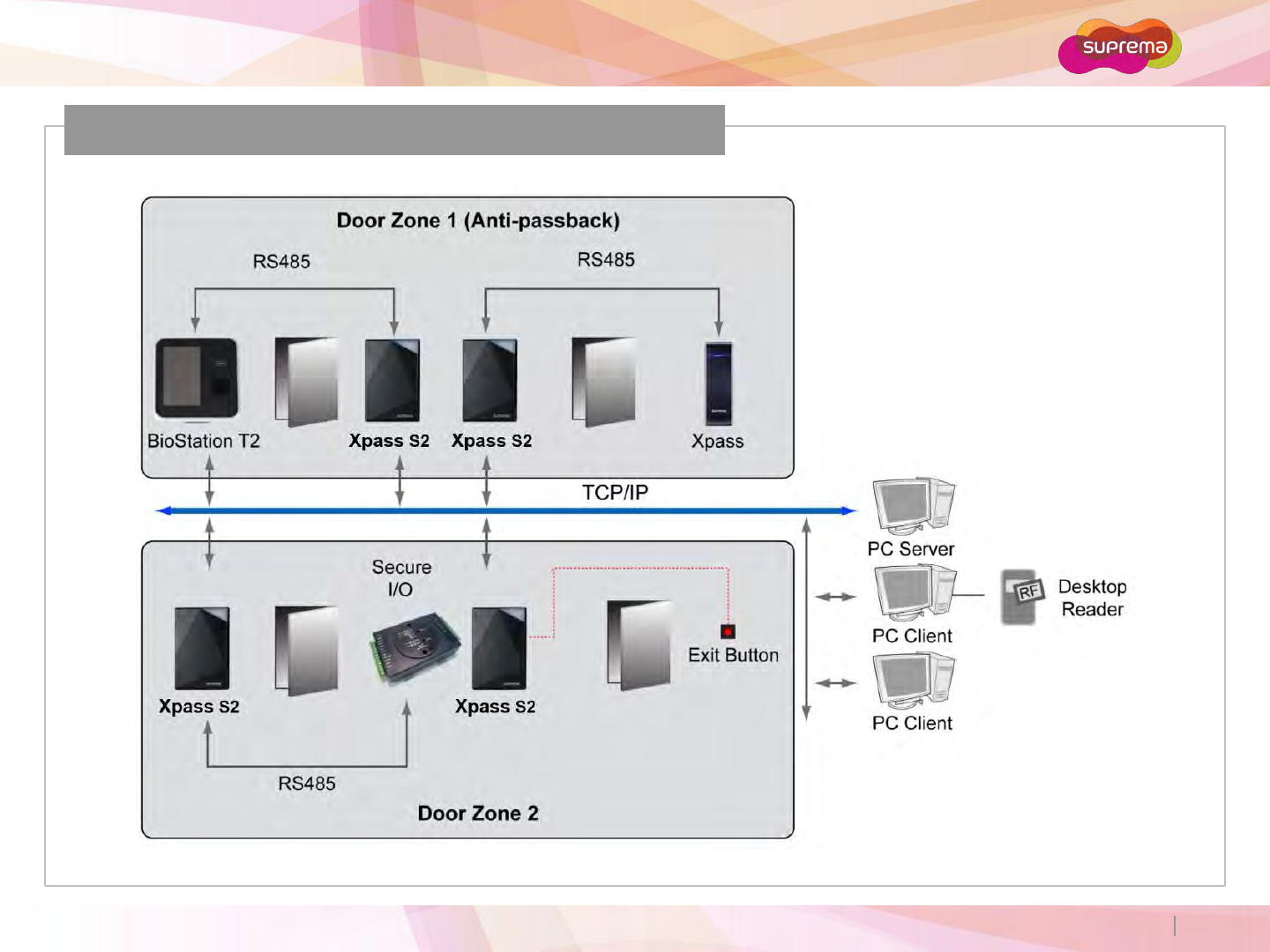
Installation Reference 3 –Network
ⒸCopyright 2007 Suprema Inc.
Xpass S2
27
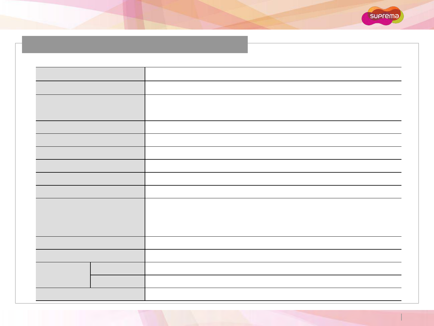
Specification
CPU 32-bit Microprocessor (533Mhz)
Memory 16MB Flash + 16MB SDRAM
RF Card 13.56MHz ISO14443A/B, ISO15693, Mifare, Desfire (CSN), Felica
User Capacity 50,000 users
Log Capacity 100,000 events
Interfaces TCP/IP, RS485, Wiegand In or Out
IP Rate IP65 dust and water protection
Sound Multi-tone buzzer
LED Multi-color LED
Input & Output Relay x 1
Switch input x 2
Power 12VDC
Operating Temperature -35°C to 65°C
Dimensions Xpass S2 80 x 120 x 11.4mm (W x H x D)
Wall Bracket 68.4 x 110.4mm (W x H)
Certificates CE, FCC, MSIP (KCC), IP65, RoHS, REACH, WEEE
ⒸCopyright 2007 Suprema Inc.
Xpass S2
28
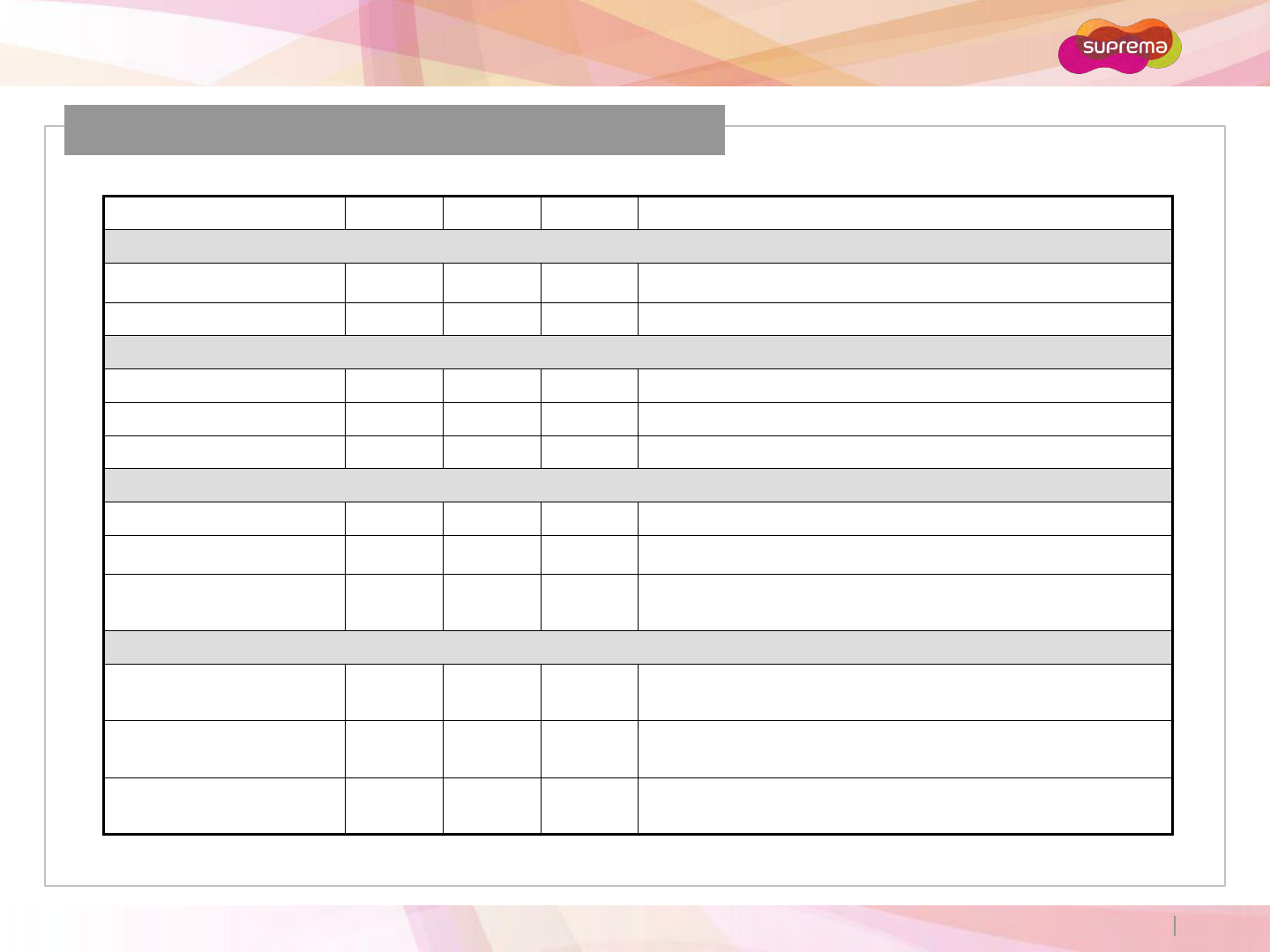
Electrical Specification
Min. Avg. Max. Notes
Power
Voltage (V) 10 12 13 Use regulated DC power adaptor only
Current (mA) - 300
Switch Input
VIH (V) - Variable -
VIL (V) - Variable
Pull-up resistance (Ω) -1K - The input ports are pulled up with 1K resistors
TTL/Wiegand Output
VOH (V) - 5 -
VOL (V) - 0.8 -
Pull-up resistance (Ω) -1K -The outputs ports are open drain type, pulled up with
1K resistors internally
Relay
Switching capacity (A) - - 1
0.3
30V DC
125V AC
Switching power
(resistive) - - 30W
37.5VA
DC
AC
Switching voltage (V) - - 110
125
DC
AC
ⒸCopyright 2007 Suprema Inc.
Xpass S2
29
FCC Rules
Changes or modifications not expressly approved by the manufacturer
responsible for compliance could void the user’s authority to operate the
equipment.
This device complies with part 15 of the FCC Rules. Operation is subject to the
following two conditions: (1) This device may not cause harmful interface, and
(2) this device must accept any interface received, including interference that
may cause undesired operation.
This equipment has been tested and found to comply with the limit of a Class B
digital device, pursuant to Part 15 of the FCC Rules. These limits are designed to
provide reasonable protection against harmful interference in a residential
installation. This equipment generates, user and can radiate radio frequency
energy and, if not installed and used in accordance with the instructions, may
cause harmful interference to radio communications.
However, there is no guarantee that interference will not occur in a particular
installation; if this equipment does cause harmful interference to radio or
television reception, which can be determined by turning the equipment off
and on, the user is encouraged to try to correct the interference by one or more
the following measures:
1. Reorient / Relocate the receiving antenna.
2. Increase the separation between the equipment and receiver.
3. Connect the equipment into an outlet on a circuit difference from that to
which the receiver is connected.
4. Consult the dealer or an experienced radio/TV technician for help
Caution
Warning
Information to User

㈜슈프리마
경기도 성남시 분당구 정자동 파크뷰 오피스타워 16층
Tel : 031-783-4510
Fax : 031-783-4503
온라인고객지원 : sales@suprema.co.kr
회사홈페이지 : www.suprema.co.kr
제품홈페이지 : www.biostation.co.kr
BioEntry Plus의 기능 및 사양은 제품의 품질 향상이나 기능 수정 등으로 인해 예고 없이 변경될 수 있습니다.
제품에 대한 자세한 사항은 ㈜슈프리마로 문의 바랍니다.