Symbol Technologies MC18N0 MC18 Personal Shopper - Barcode Scanner User Manual
Symbol Technologies Inc MC18 Personal Shopper - Barcode Scanner
UserManual.wiki
>
Symbol Technologies
>
MC18N0 User Manual
>
User Manual (2 of 2).pdf
Contents
1.
User Manual (1 of 2).pdf
2.
User Manual (2 of 2).pdf
3.
User Manual (Statements).pdf
4.
User Manual_rev.pdf
5.
User manual (statements)
6.
User manual rev
User Manual (2 of 2).pdf
Navigation menu
Upload a User Manual
Namespaces
Wiki Guide
HTML
PDF
Info
Views
User Manual
Discussion / Help
Navigation
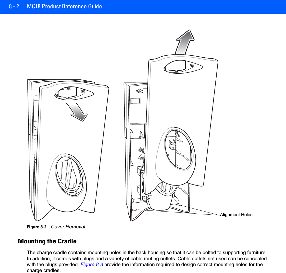
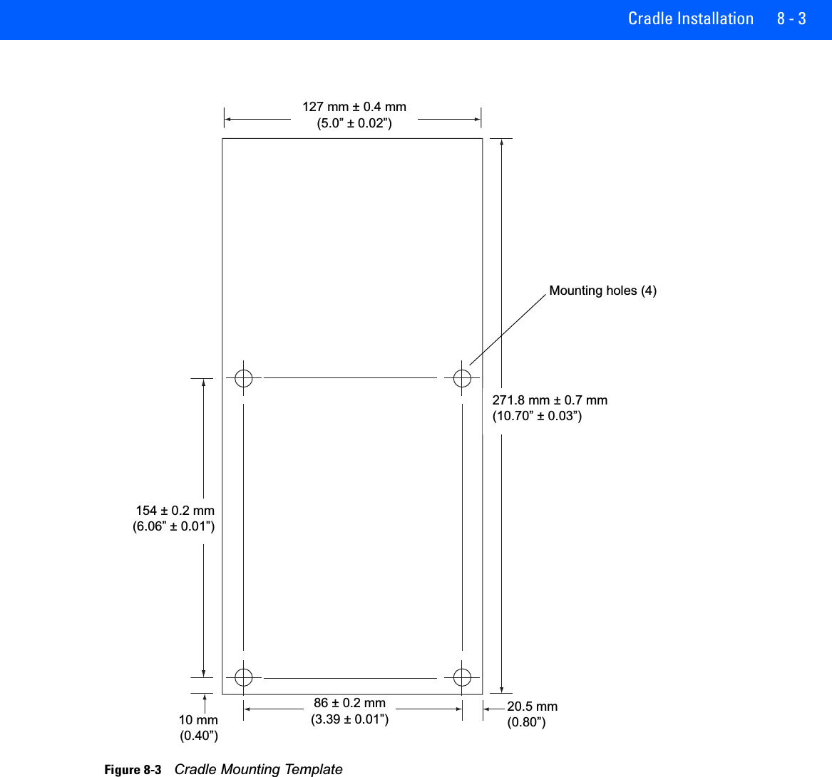
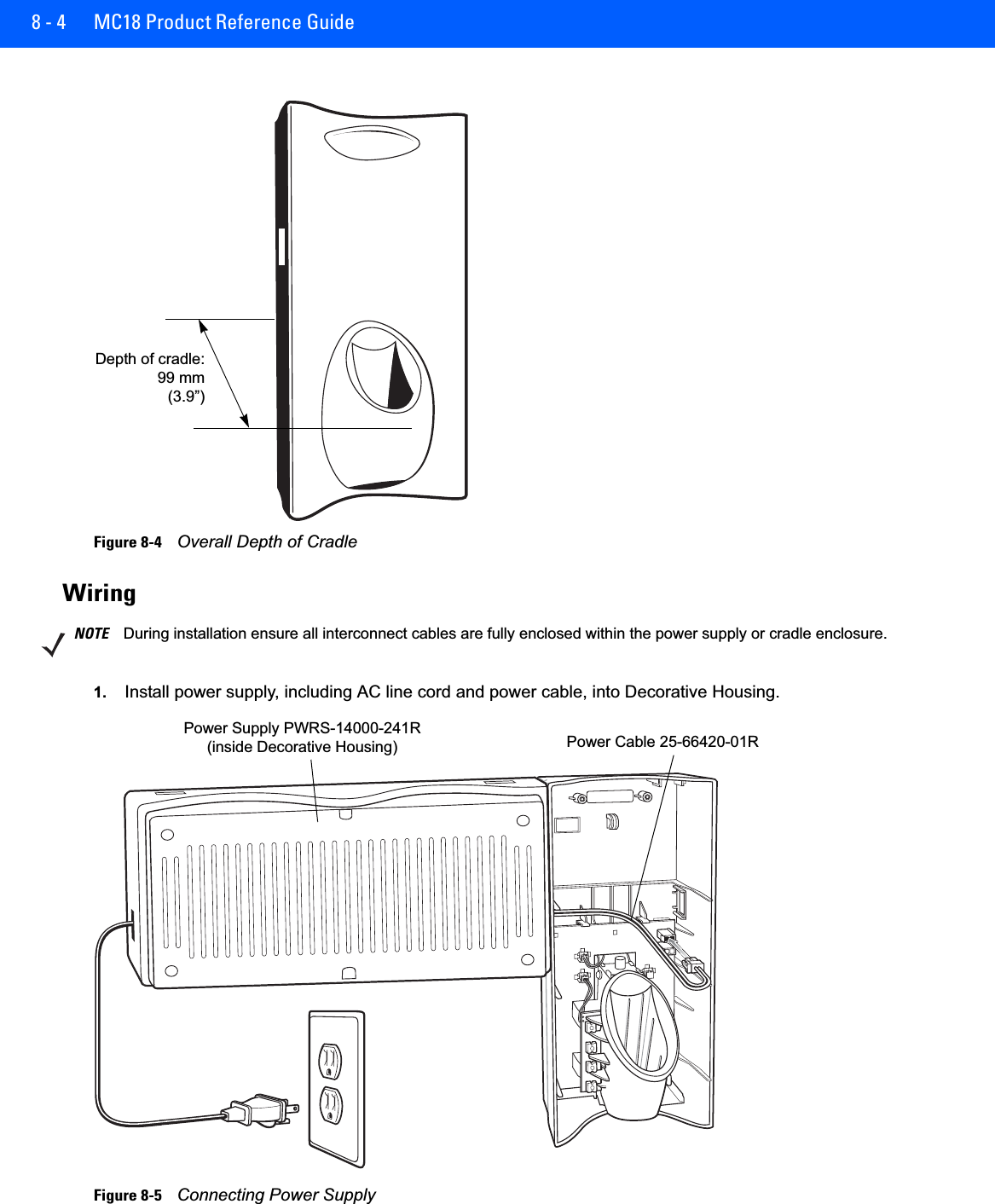
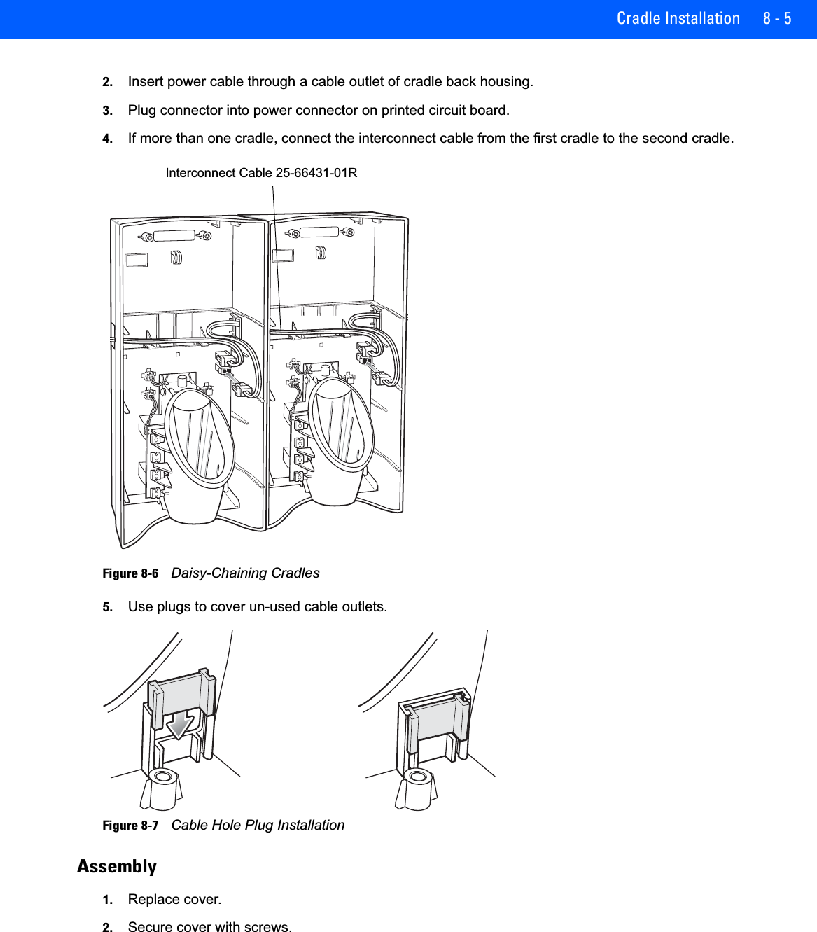
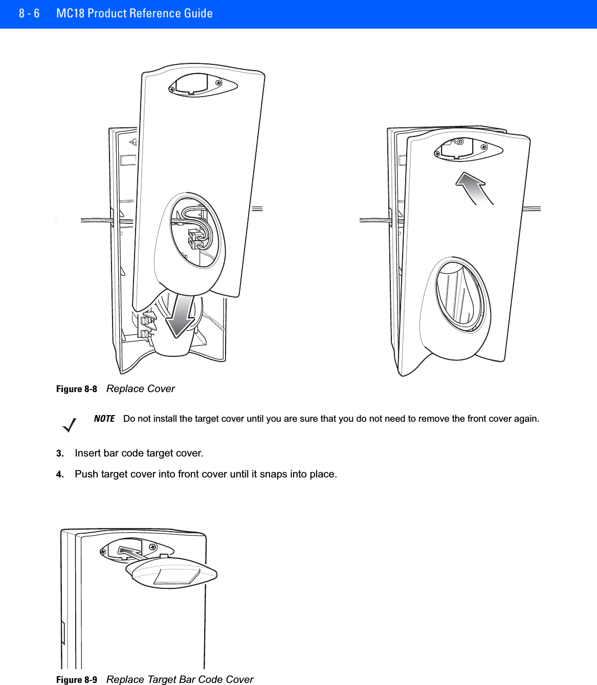
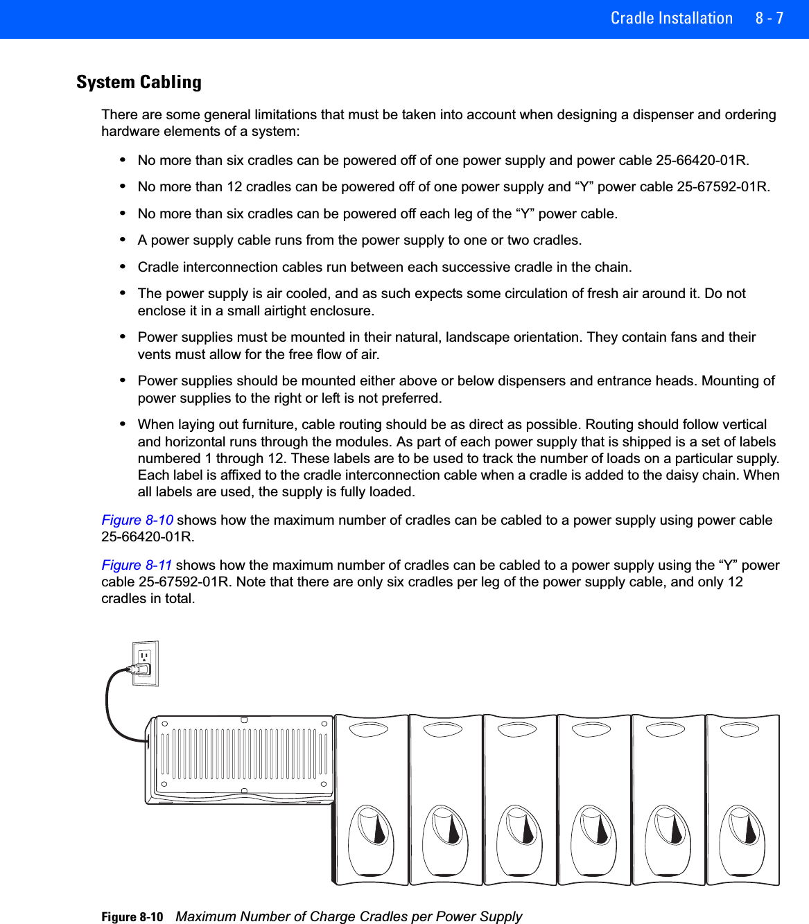
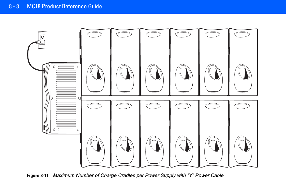
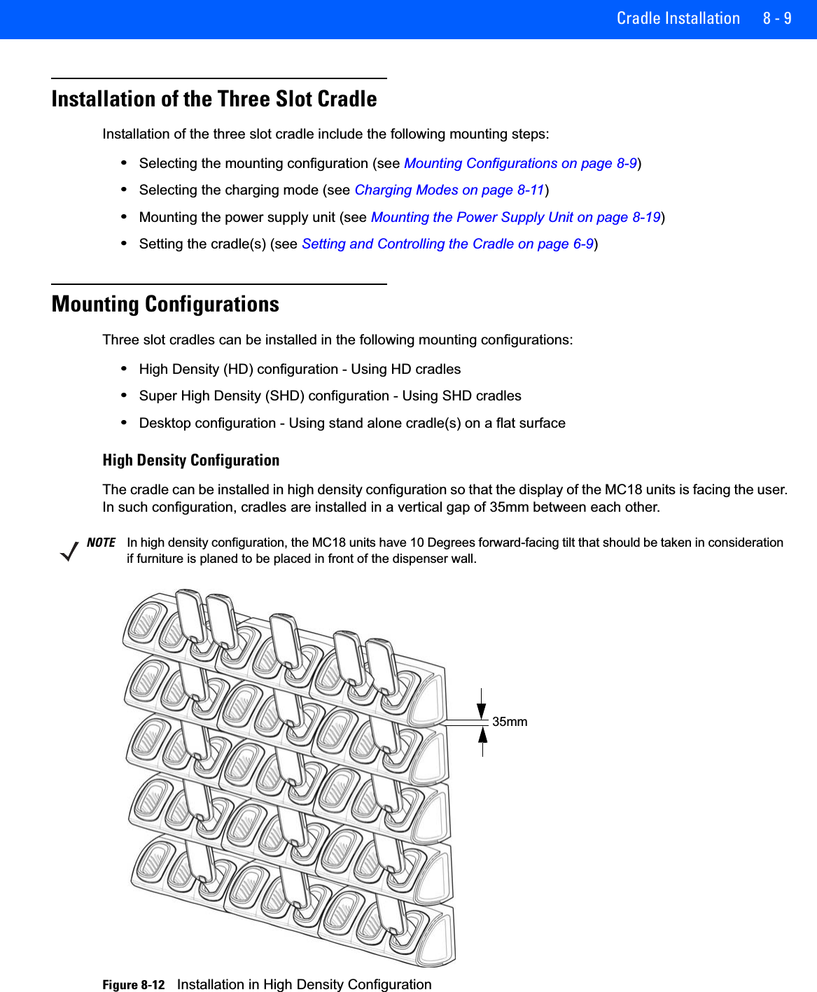
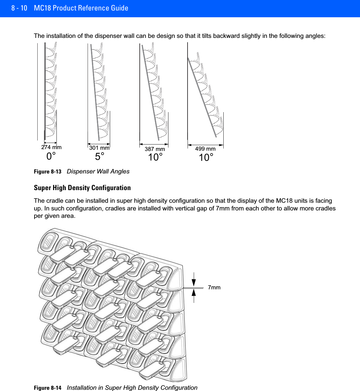
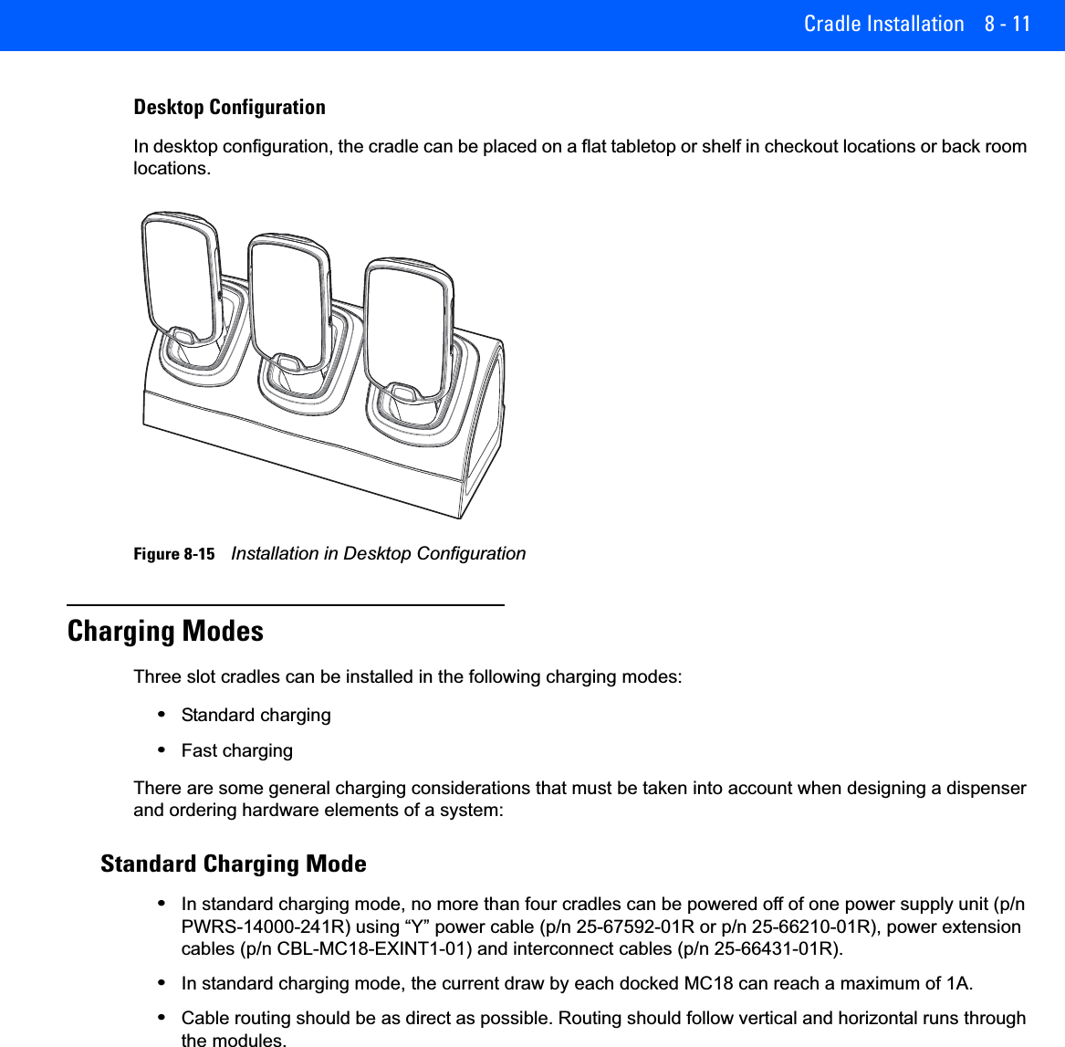
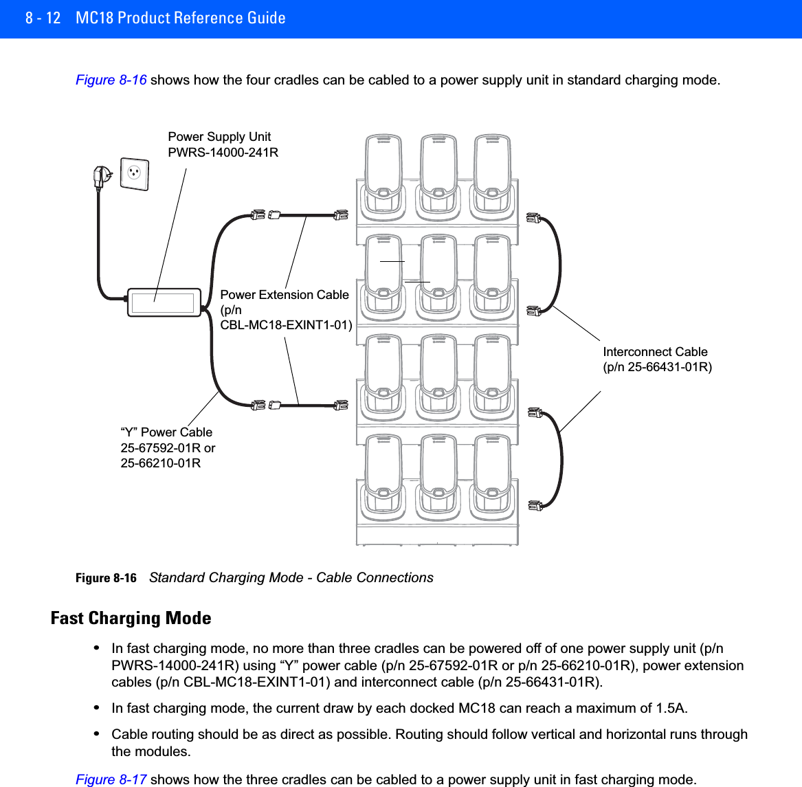
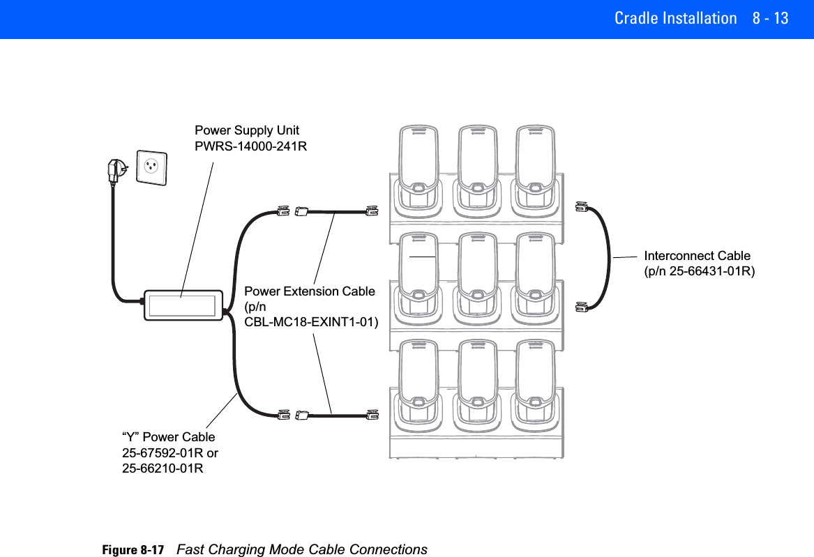
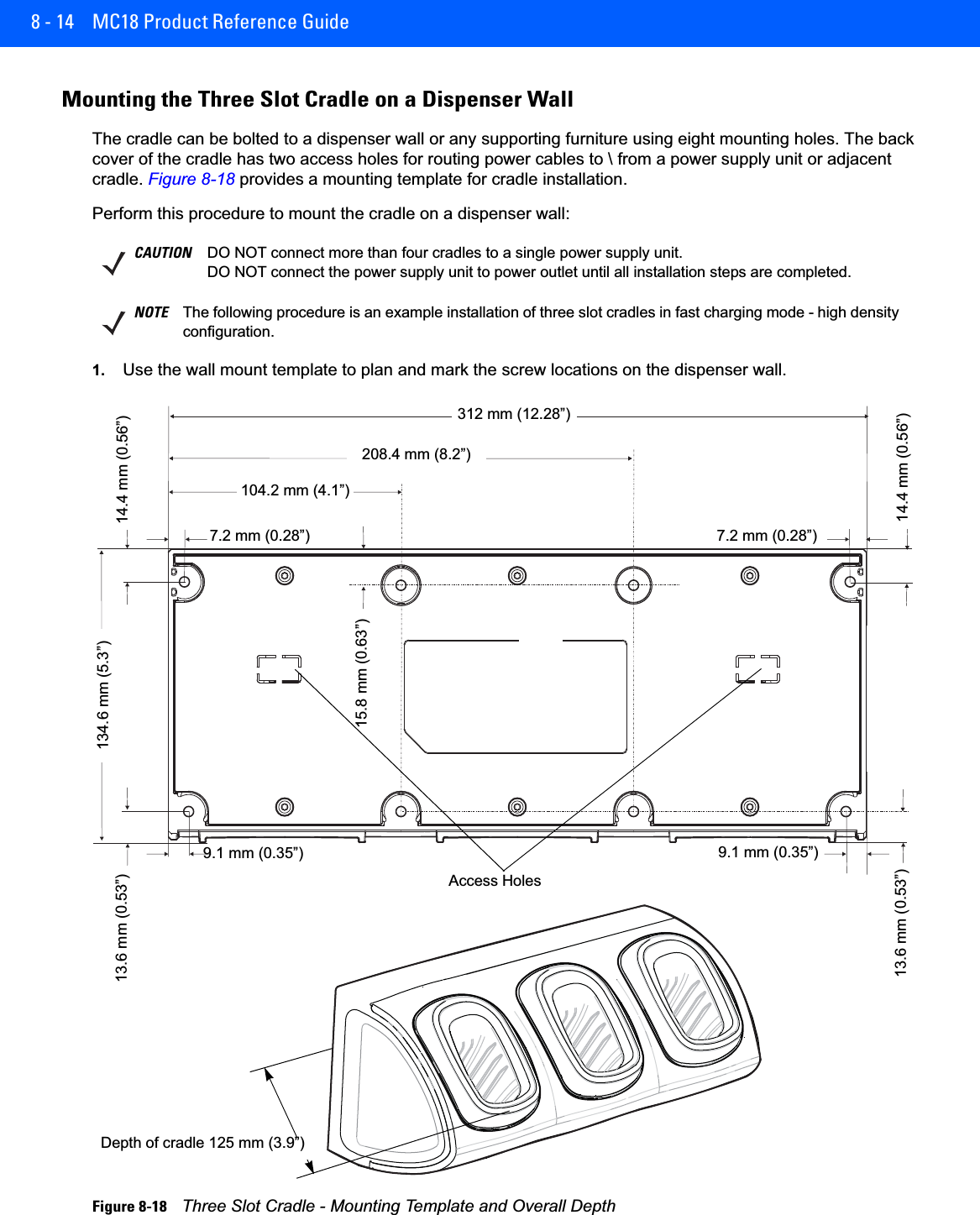
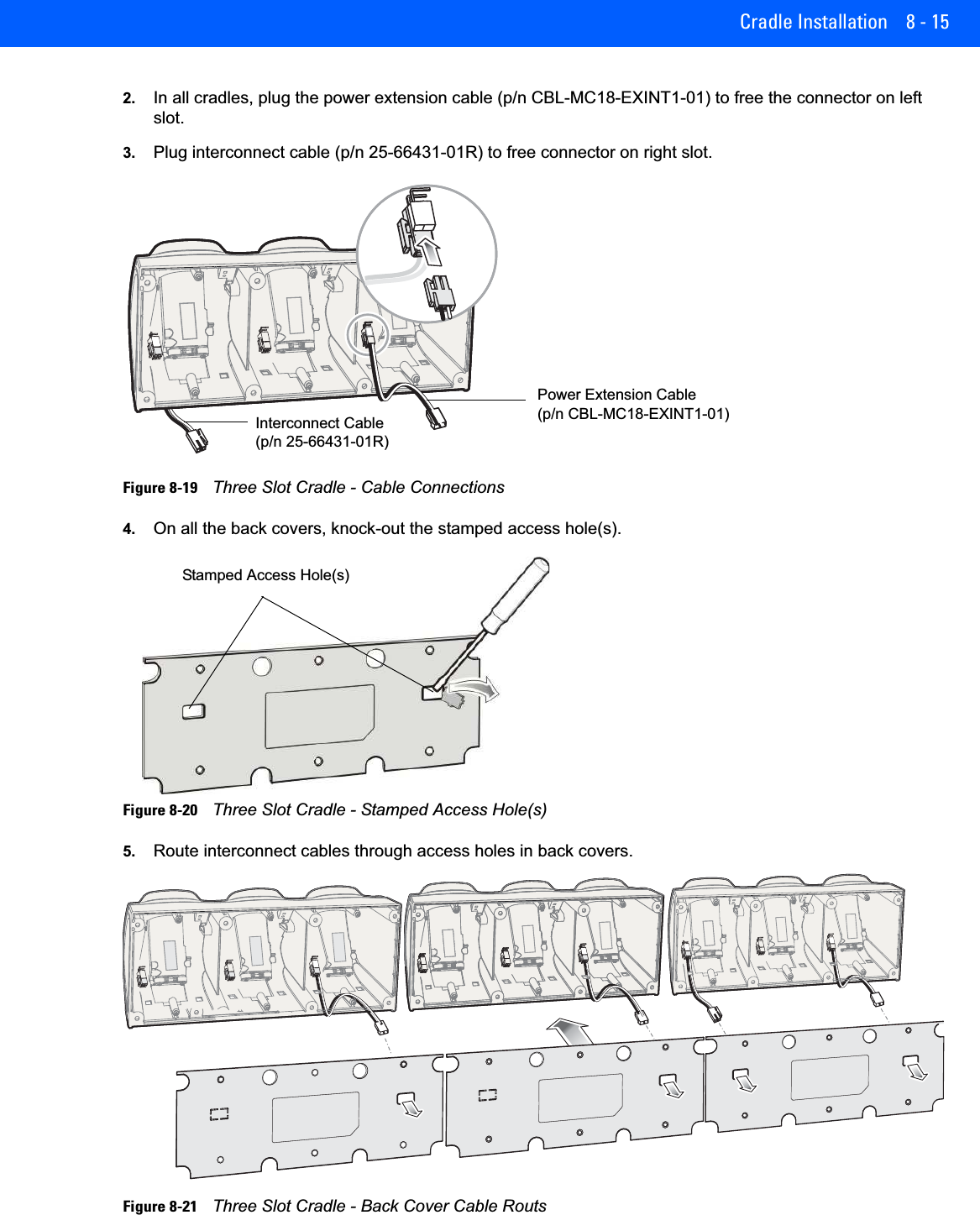
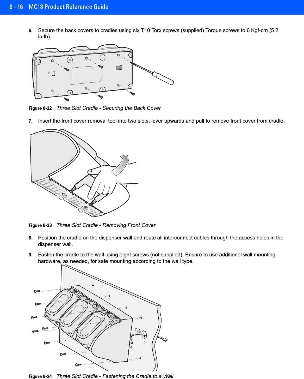
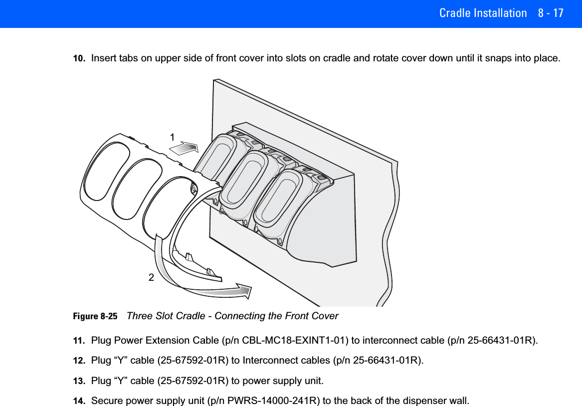
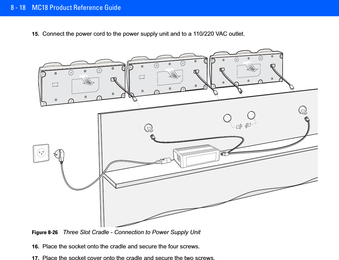
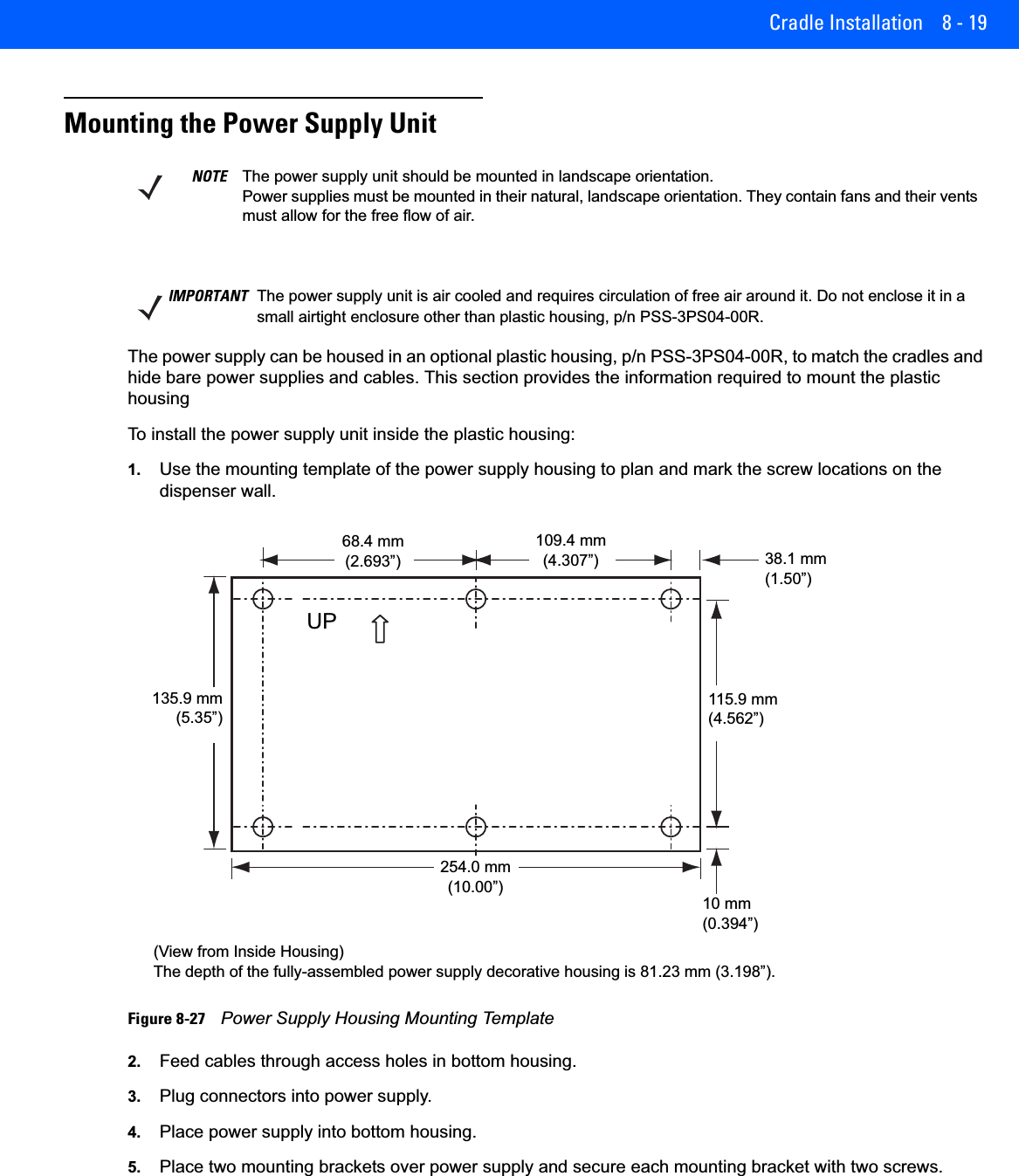
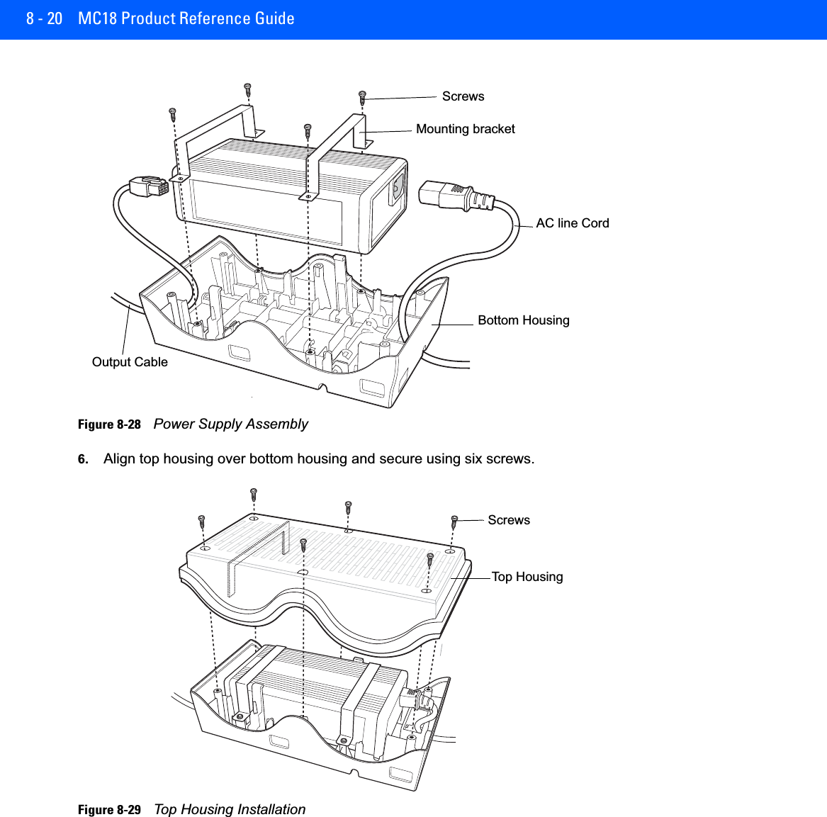
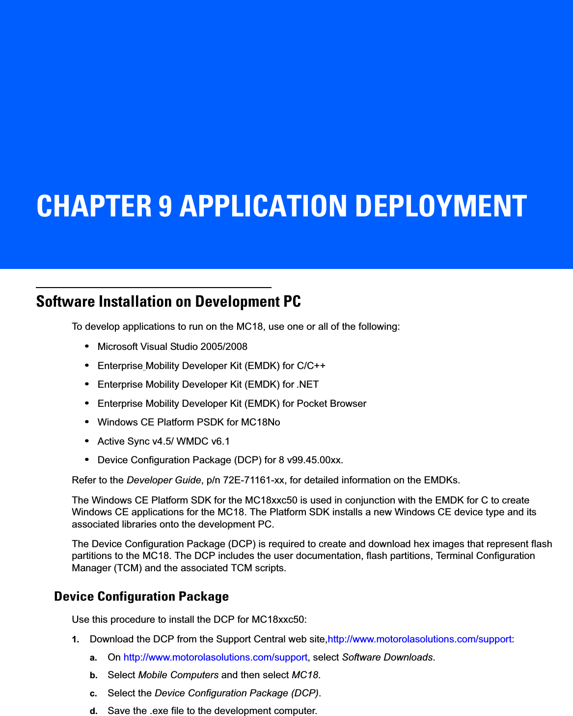


![B - 2 MC18 Product Reference Guide4. The following lists the five default menu items that appear on the App Launcher display. Note that Exit menu item is not listed in the registry file.[HKEY_CURRENT_USER\Software\Symbol\Launcher\Default\Programs\Prog1]"Description"="RD Client""Name"="\\windows\\rdclient.exe""Command"=""[HKEY_CURRENT_USER\Software\Motorola\AppLauncher\Profiles\DefaultProf\Default\Programs]"Description"="SPB""Name"="\\program files\\SPB2_CE.exe""Command"=""[HKEY_CURRENT_USER\Software\Symbol\Launcher\Default\Programs\Prog3]"Description"="Device Info""Name"="\\Windows\\DeviceInfoApp.exe""Command"=""[HKEY_CURRENT_USER\Software\Symbol\Launcher\Default\Programs\Prog4]"Description"="MC18-Scan""Name"="\\Application\\MC18-Scan.EXE""Command"=""[HKEY_CURRENT_USER\Software\Symbol\Launcher\Default\Programs\Prog5]"Description"="Reset""Name"="\\Windows\\WarmBoot.EXE""Command"=""Use this procedure to add a sixth item to the list, enter the following after the warm boot entry:[HKEY_CURRENT_USER\Software\Symbol\Launcher\Default\Programs\Prog6]"Description"="Control Panel""Name"="\\Windows\\CtlPanel.EXE""Command"=""1. Save the registry file.2. Copy the file back to the /Application folder on the MC18.3. Cold boot the MC18.](https://usermanual.wiki/Symbol-Technologies/MC18N0.User-Manual-2-of-2-pdf/User-Guide-2353666-Page-56.png)