Symbol Technologies MC18N0 MC18 Personal Shopper - Barcode Scanner User Manual MC18 Product Reference Guide
Symbol Technologies Inc MC18 Personal Shopper - Barcode Scanner MC18 Product Reference Guide
UserManual.wiki
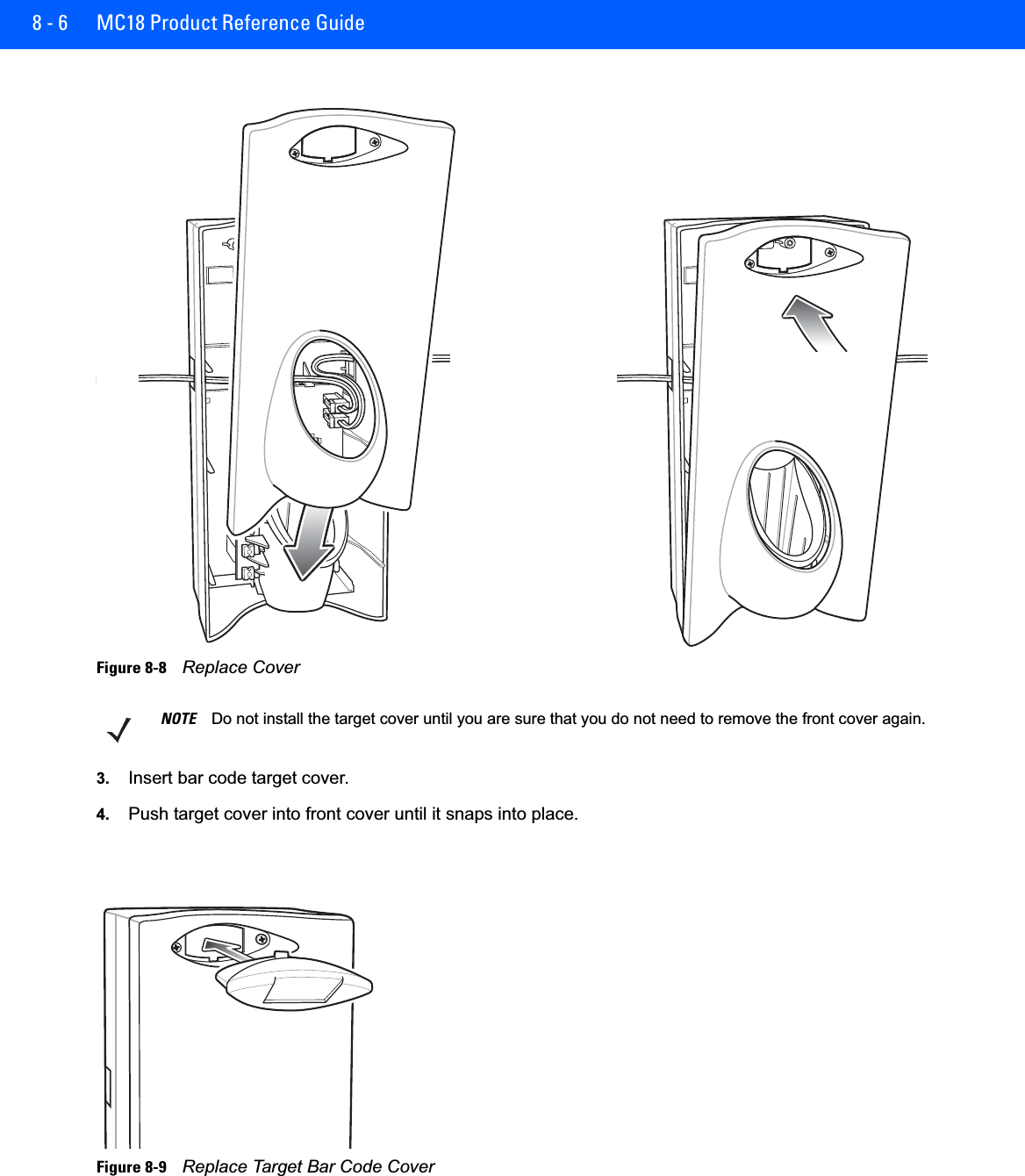
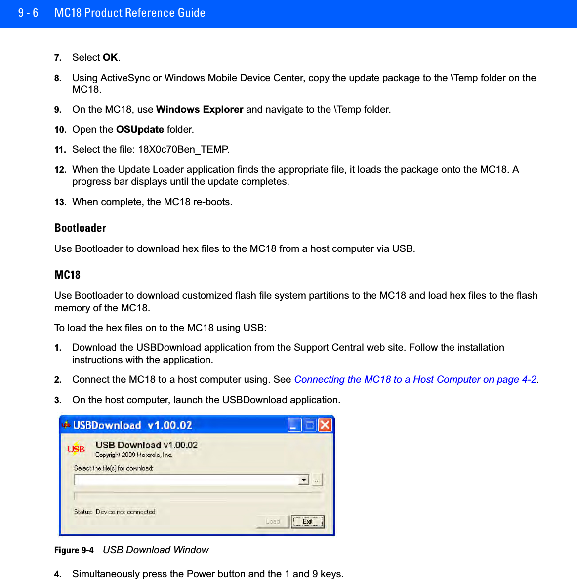
>
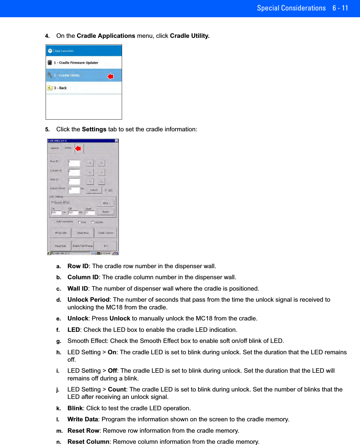
Symbol Technologies
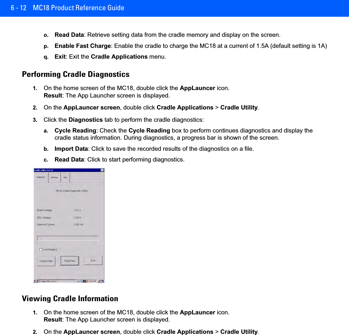
>
MC18N0 User Manual
>
User Manual_rev.pdf
Contents
1.
User Manual (1 of 2).pdf
2.
User Manual (2 of 2).pdf
3.
User Manual (Statements).pdf
4.
User Manual_rev.pdf
5.
User manual (statements)
6.
User manual rev
User Manual_rev.pdf
Navigation menu
Upload a User Manual
Namespaces
Wiki Guide
HTML
PDF
Info
Views
User Manual
Discussion / Help
Navigation

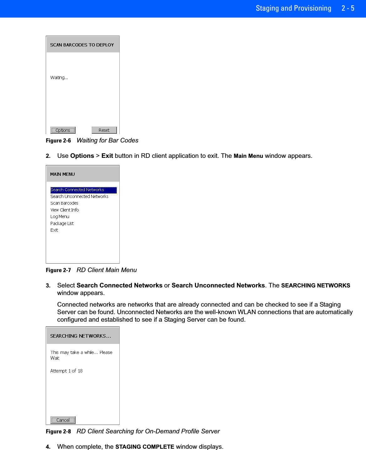
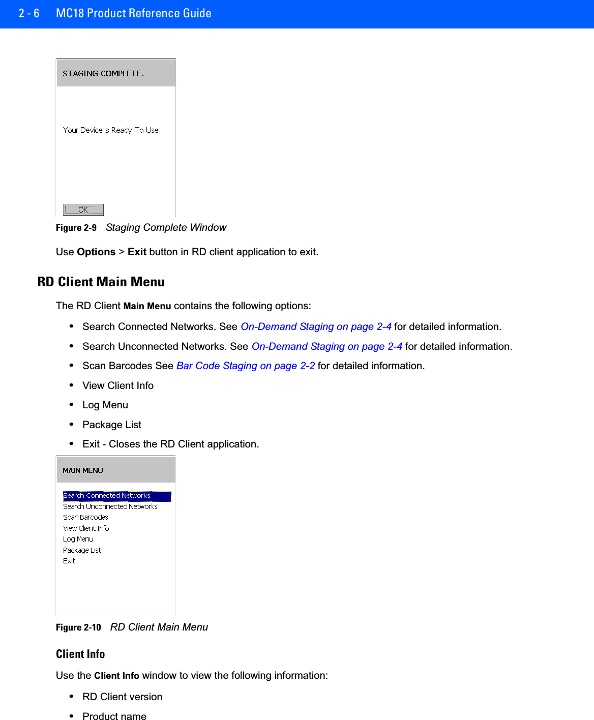
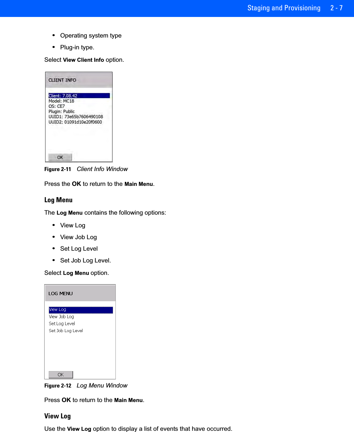
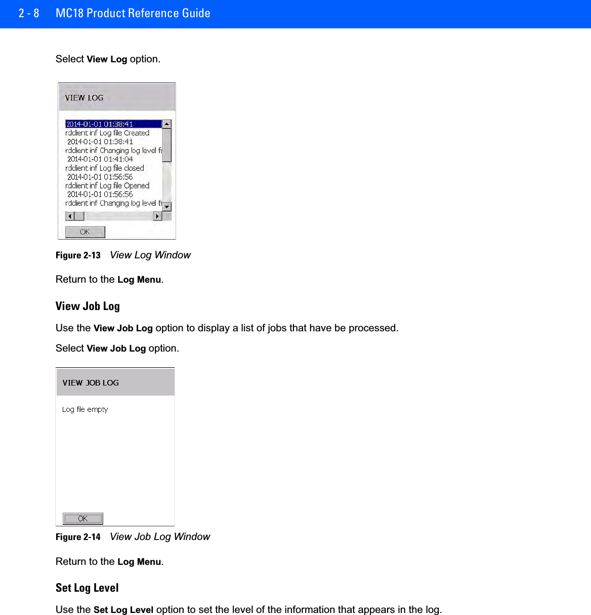
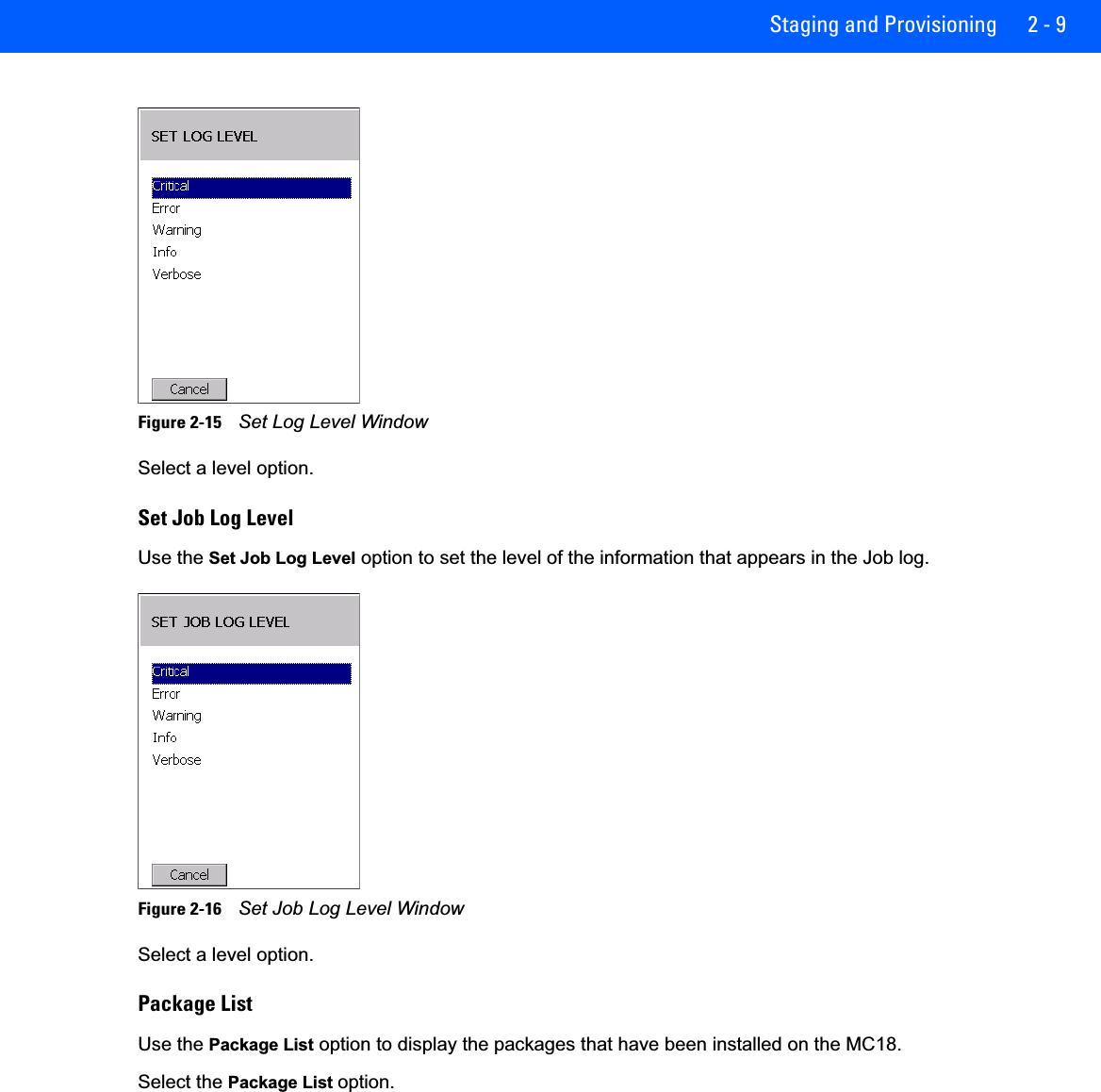
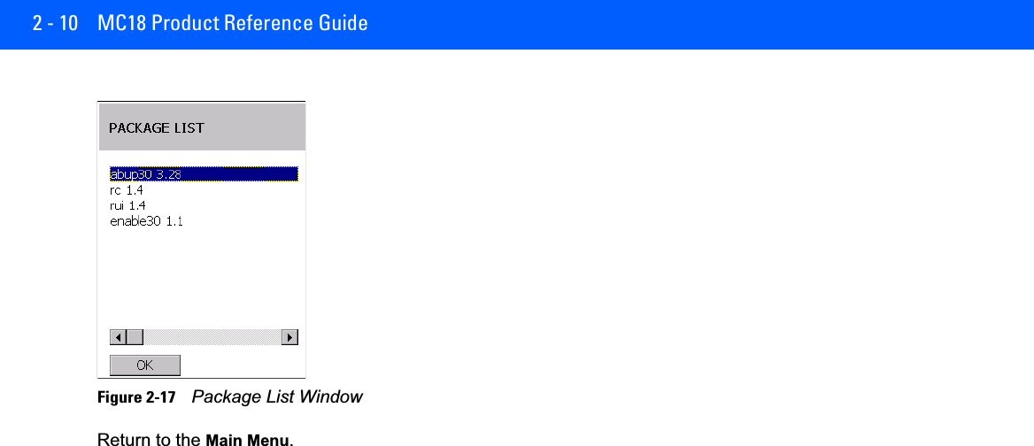
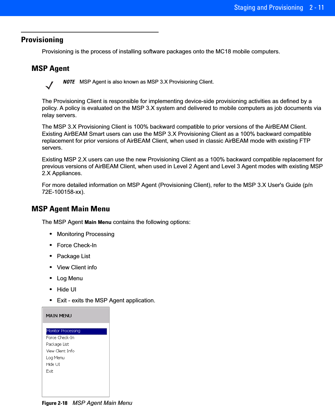
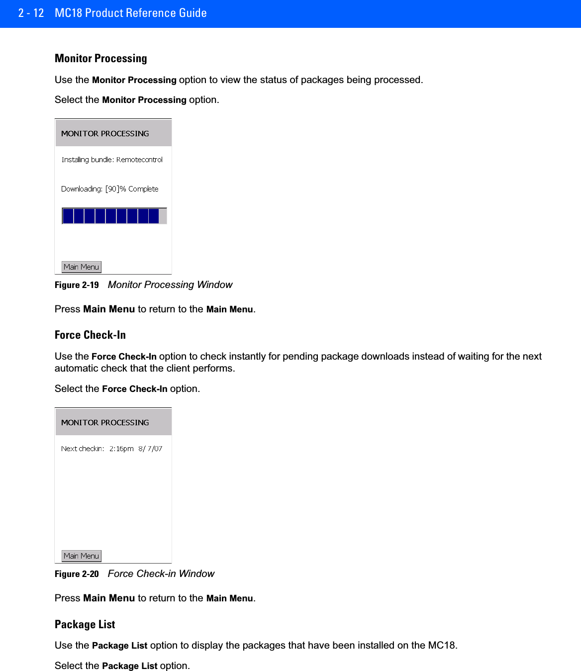
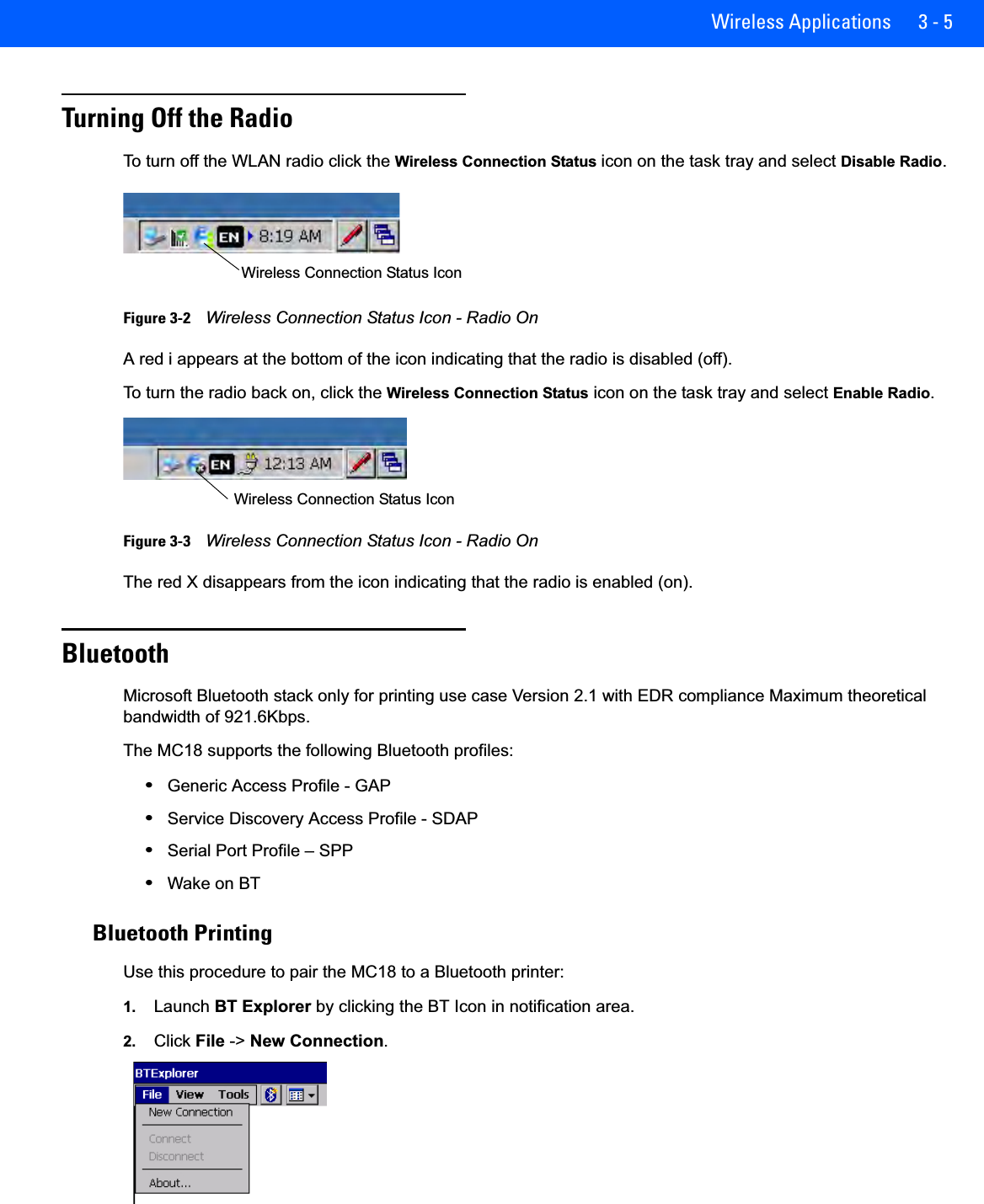
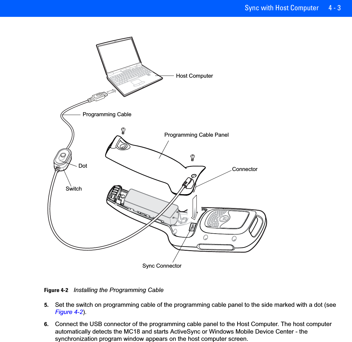
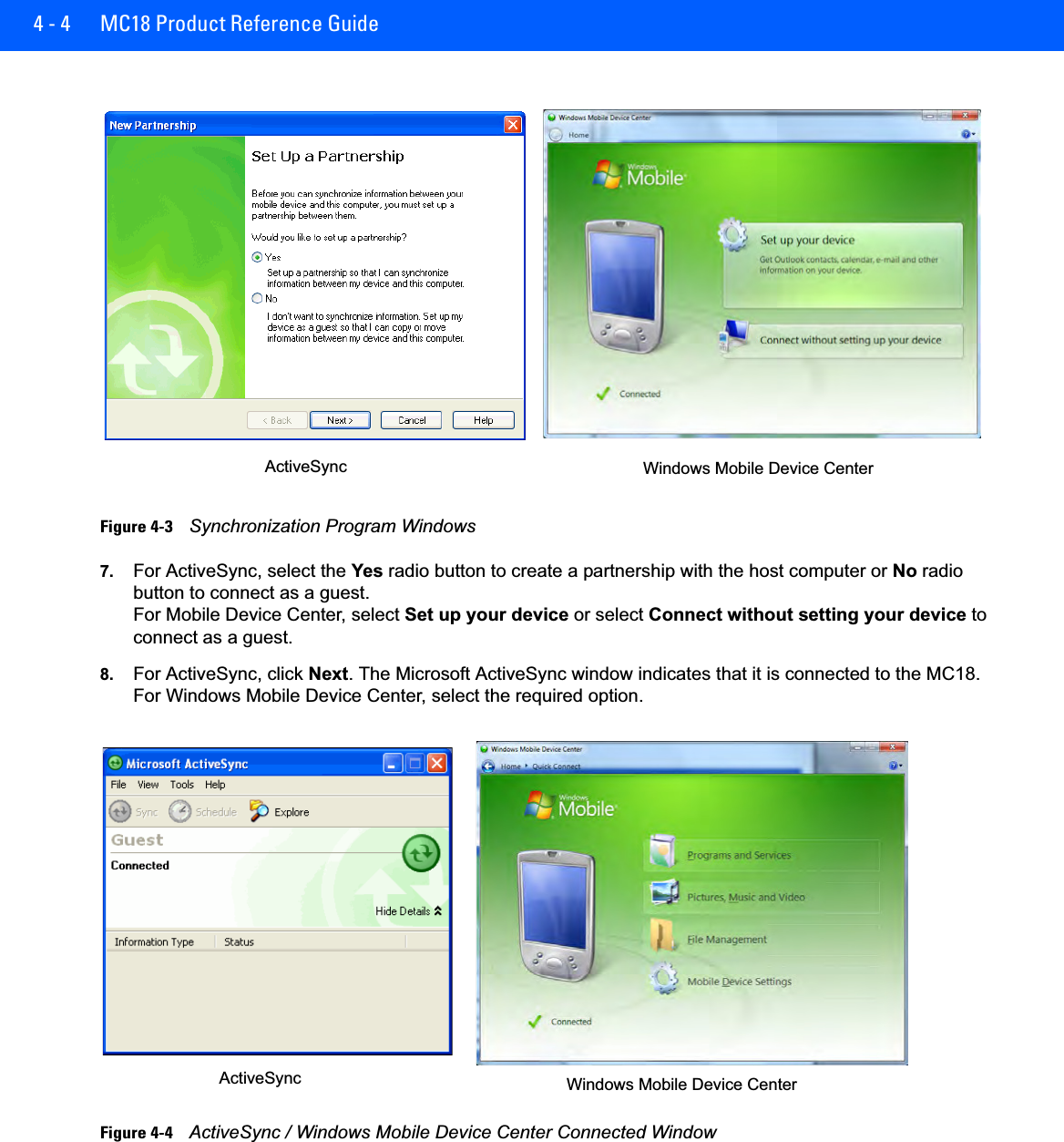
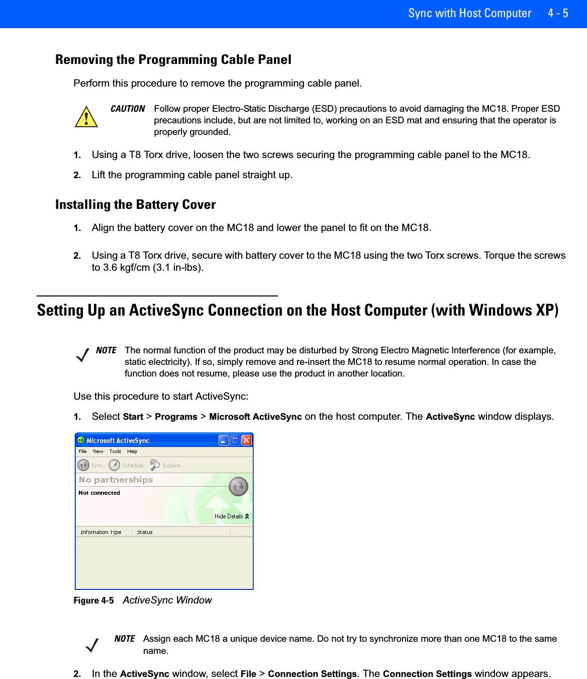
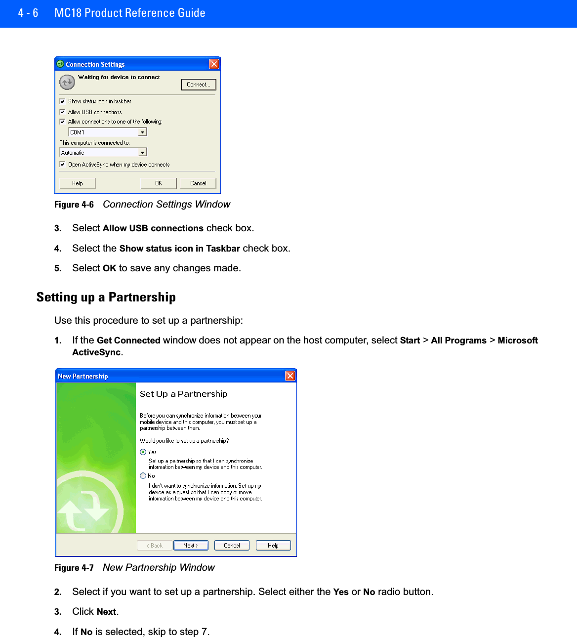
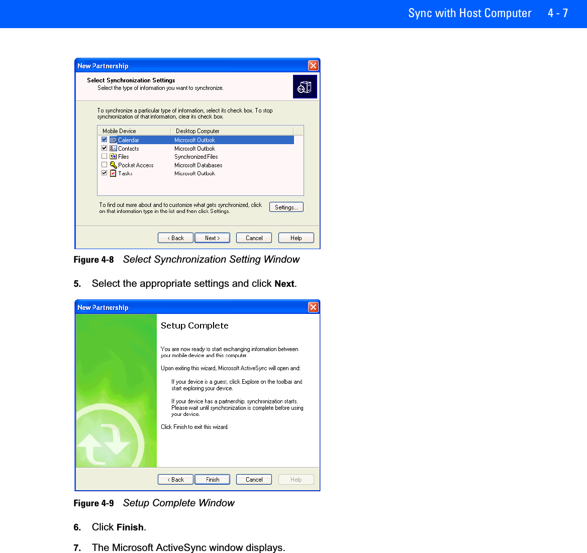
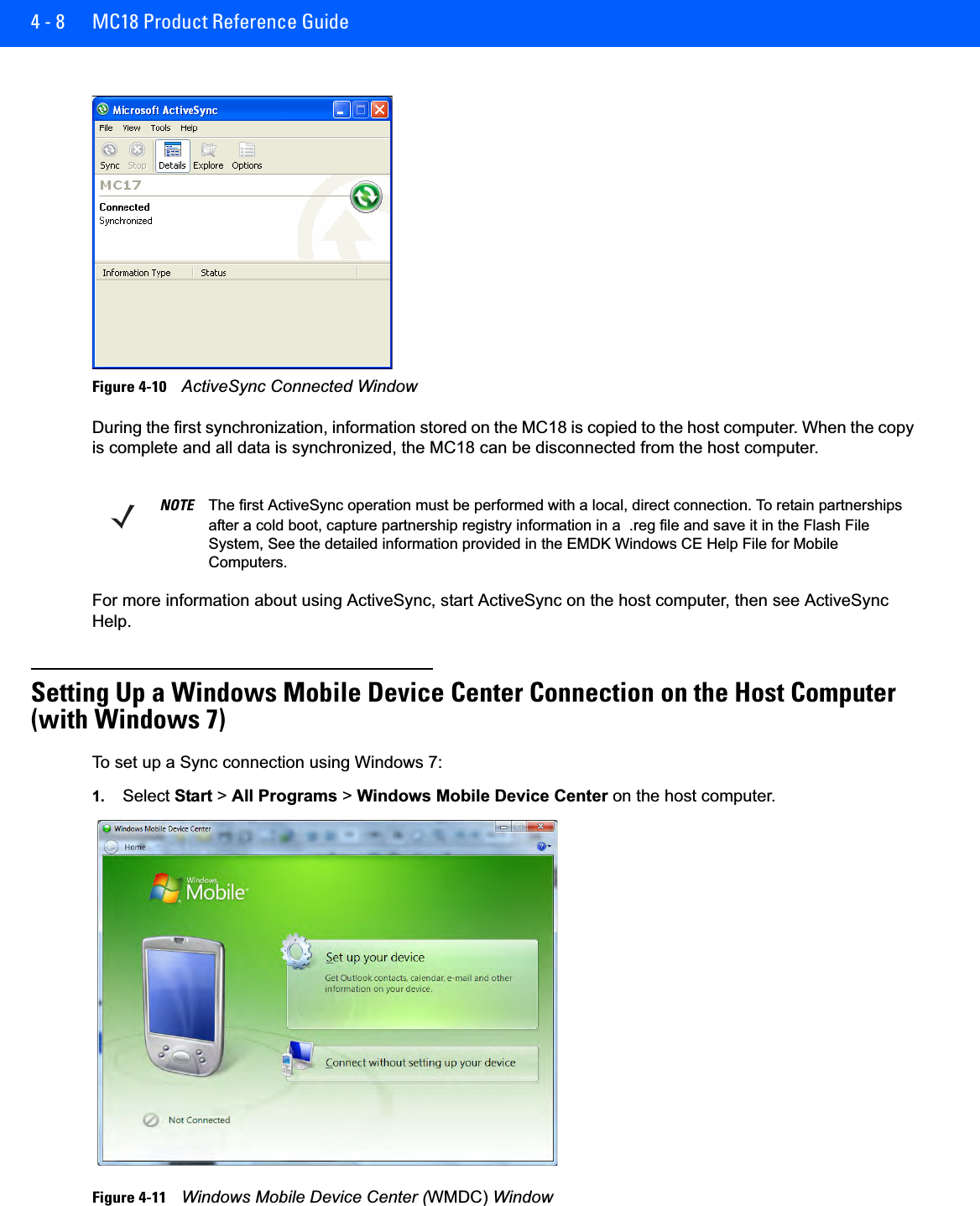
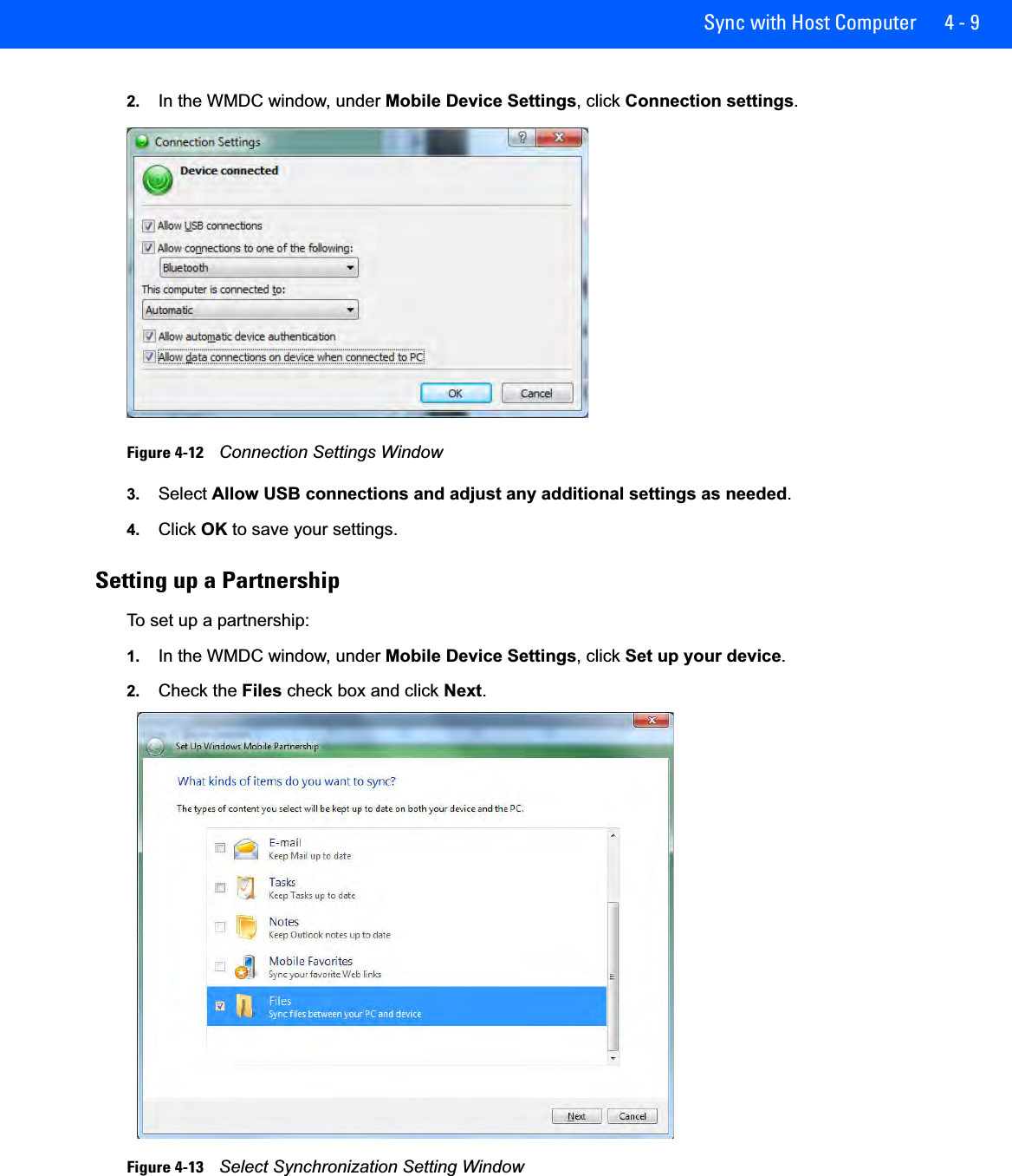
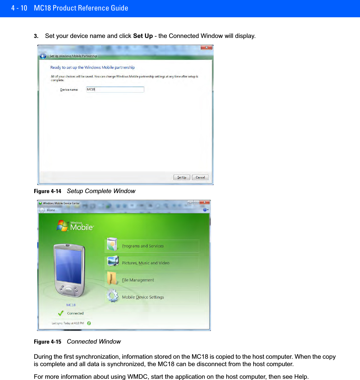

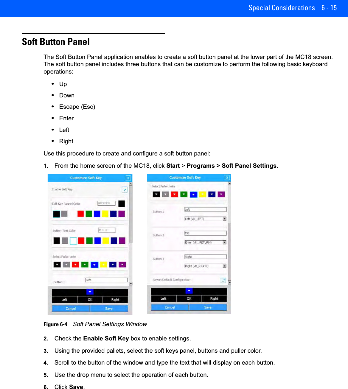
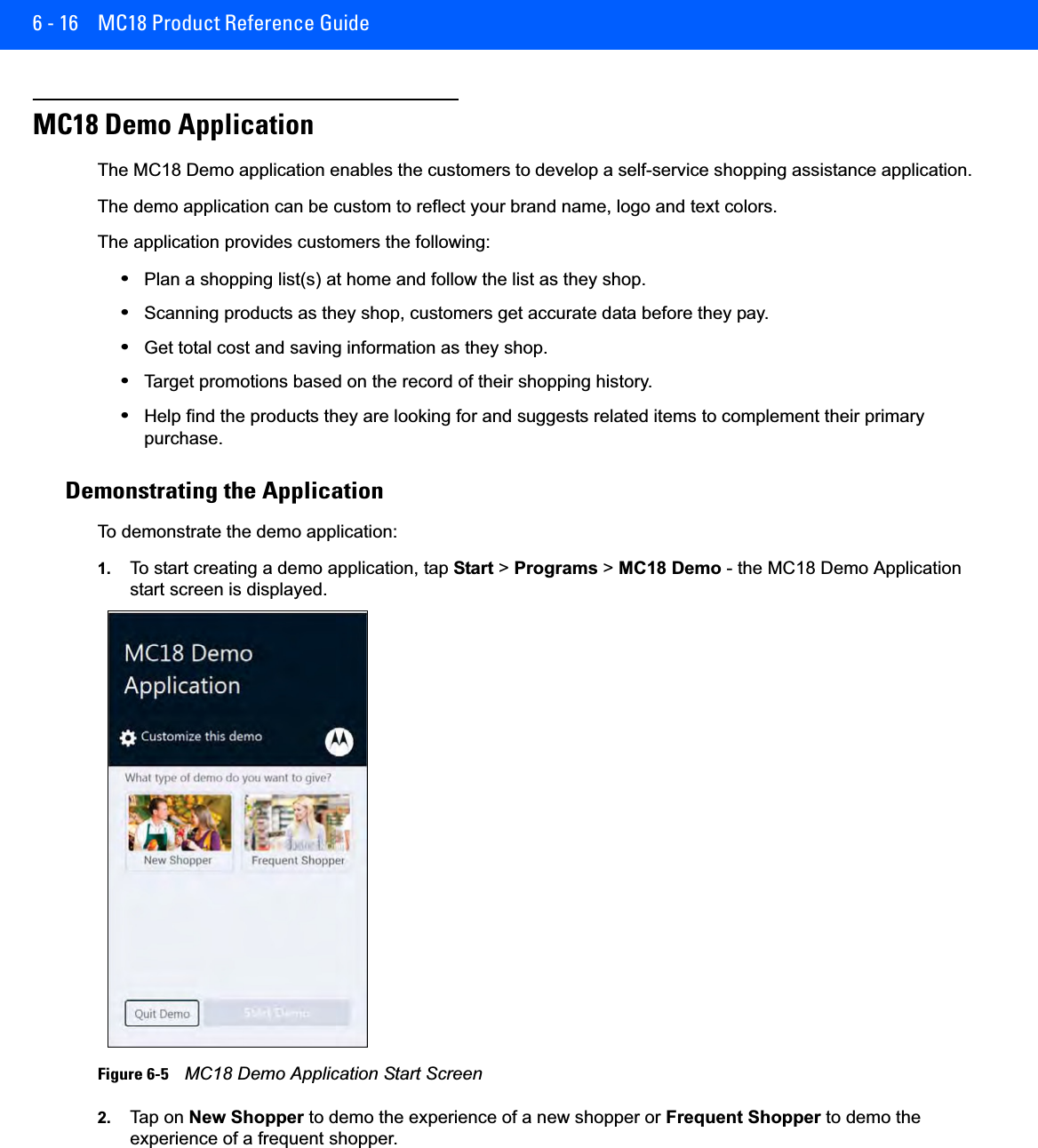
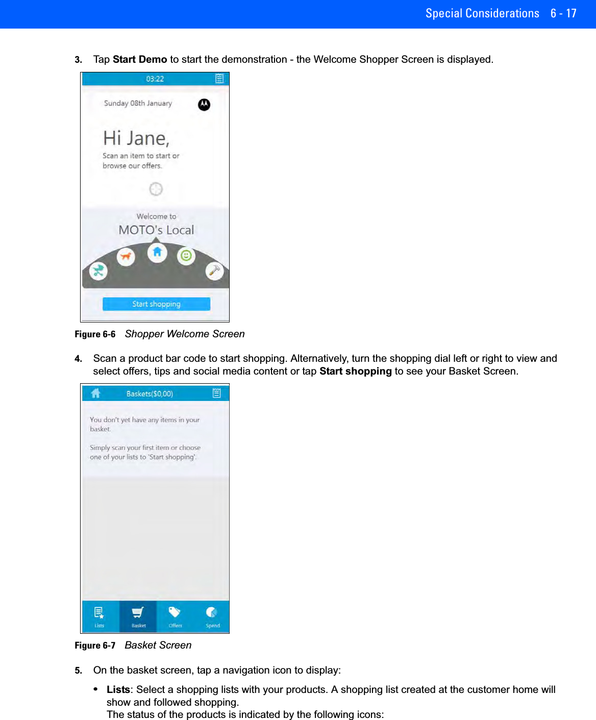
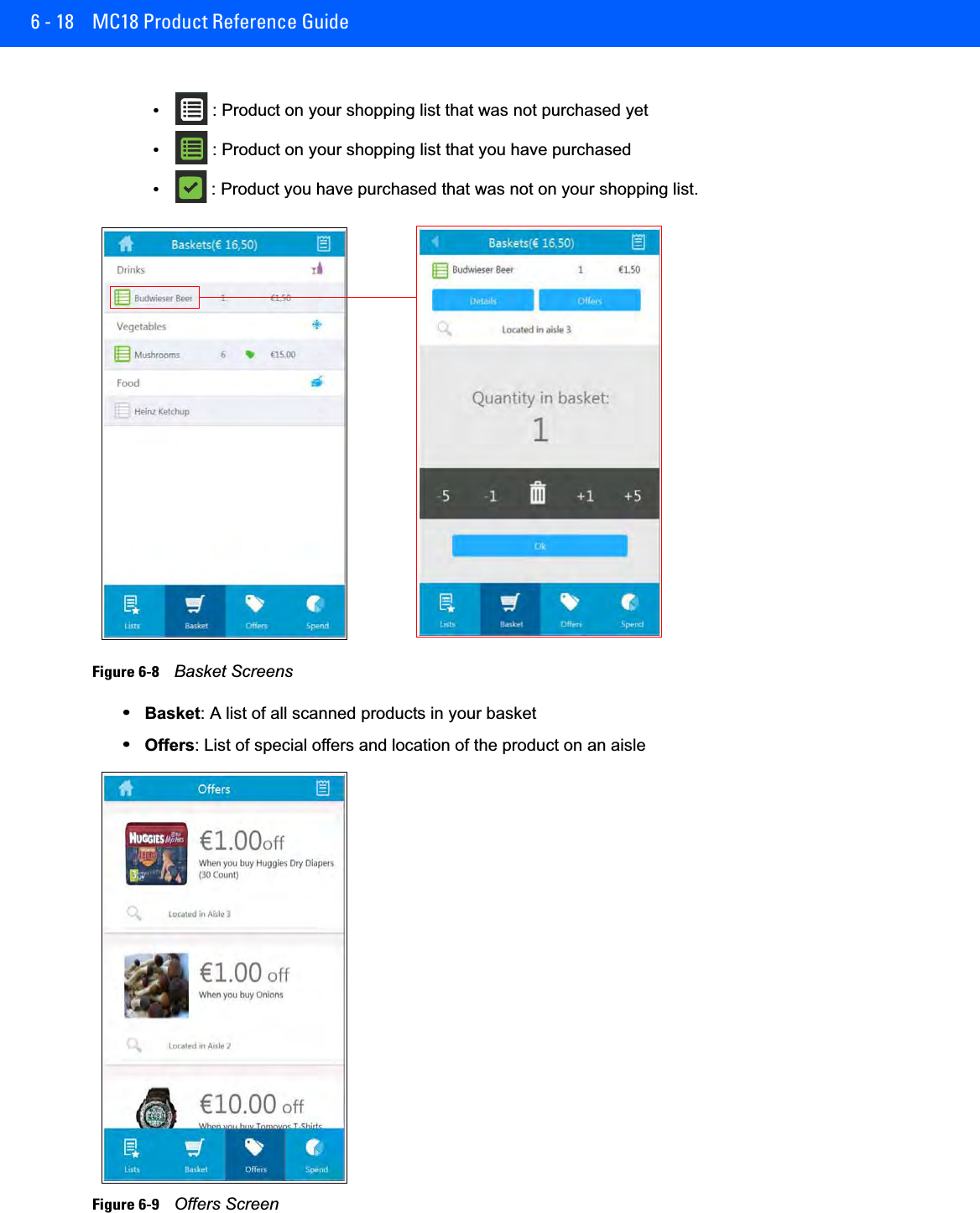
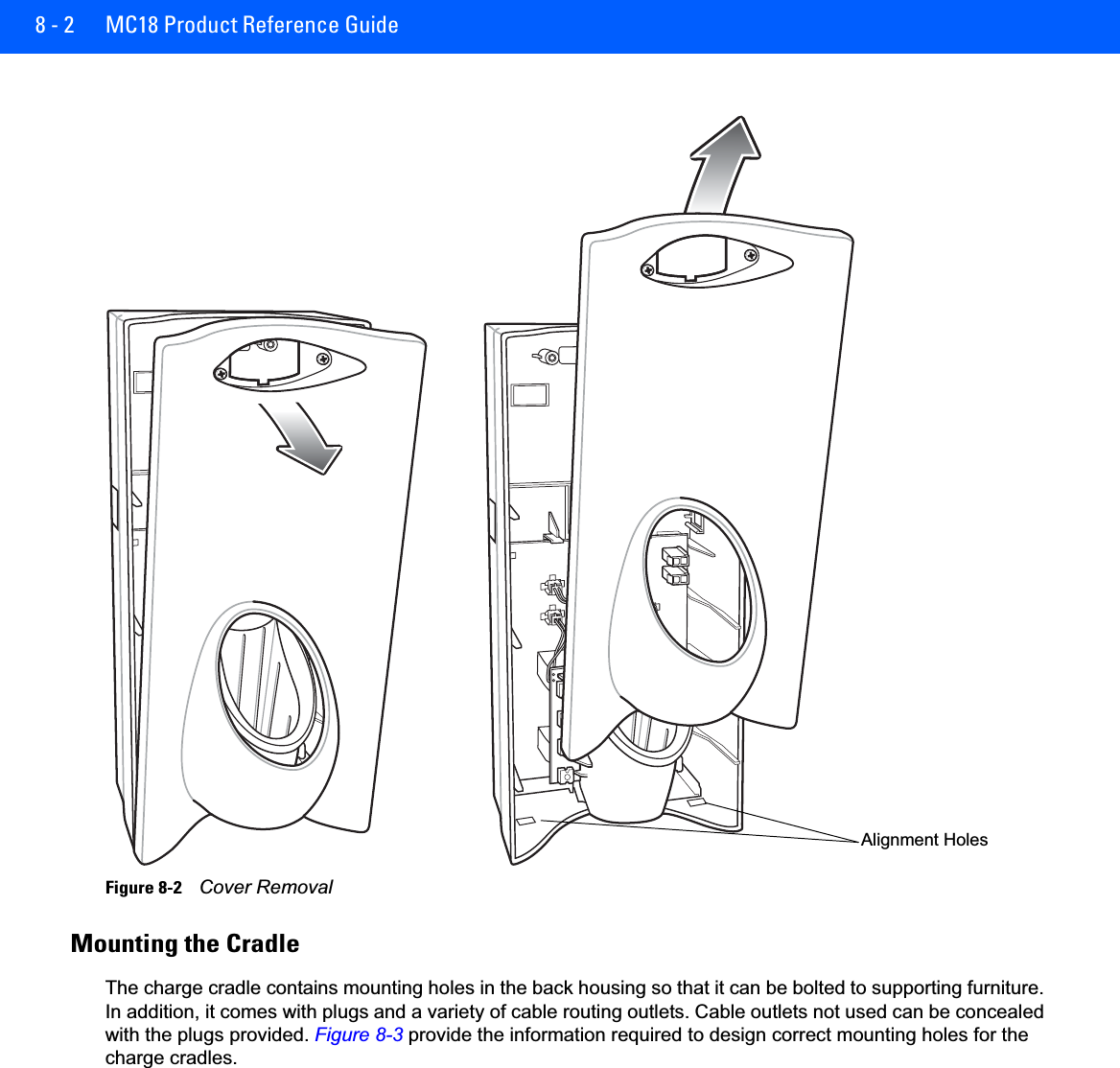
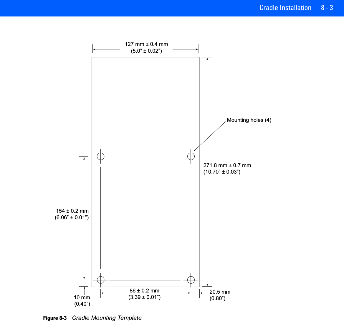
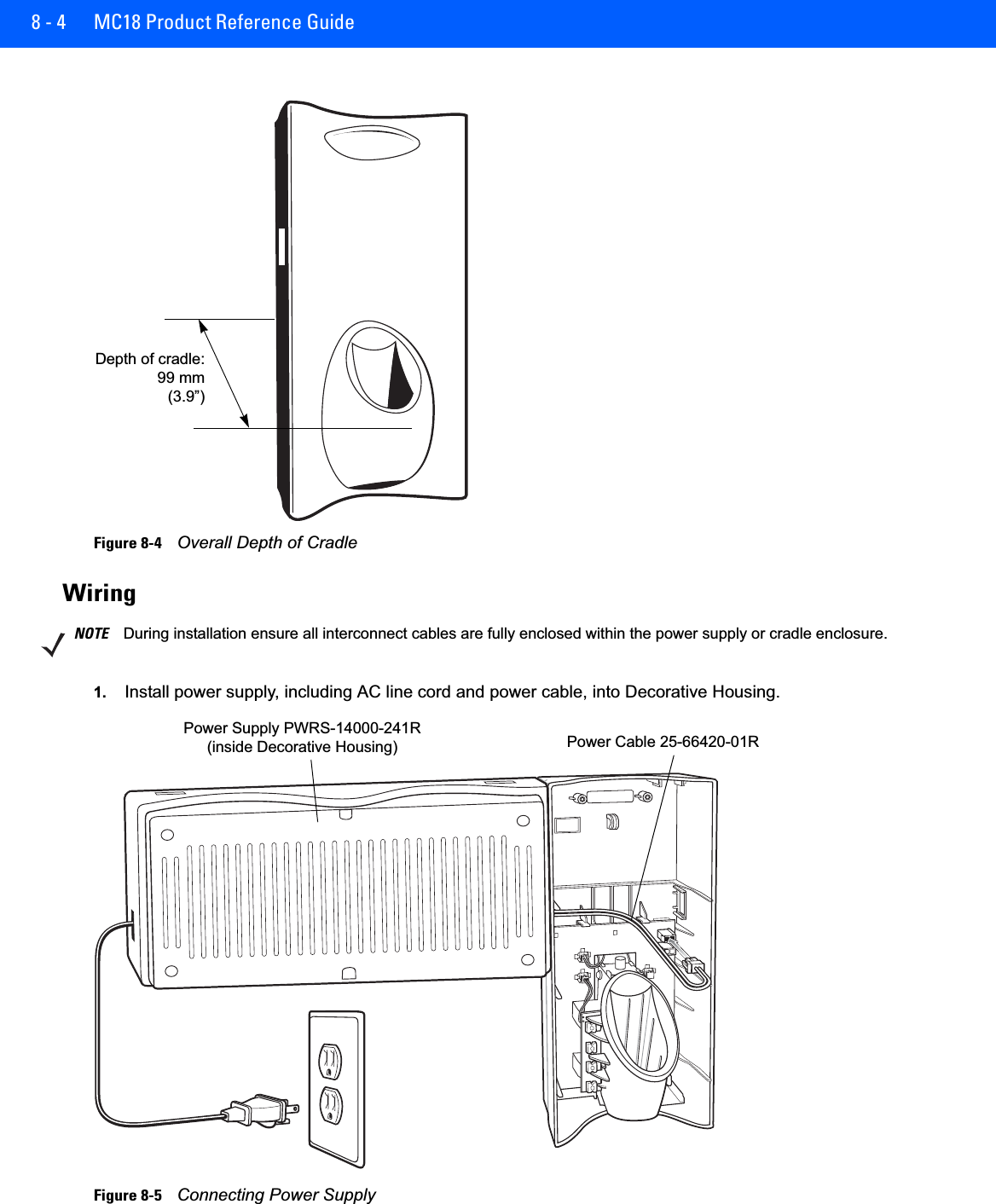
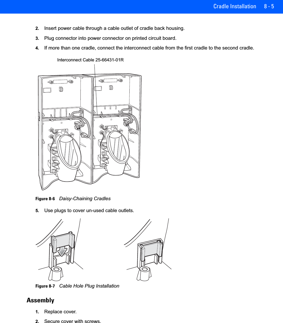
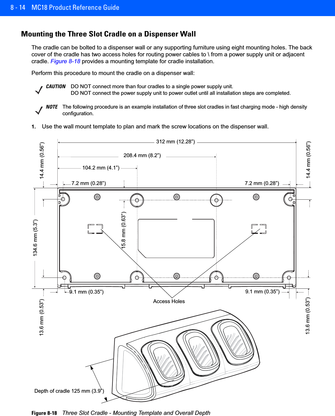
![Special Considerations 6 - 51. Select Start > Settings > Control Panel > Backlight icon > Battery Power tab.2. Select the On battery power: Disable backlight if not used for: check box and select a value from the drop-down list box.3. Select the Brightness tab.4. Select the Disable backlight check box to completely turn off the display backlight.5. Use the slider to set the brightness of the backlight. Set it to a low value to save battery power.6. Select OK.The display backlight value can also be set using a registry setting.Key Name: [HKEY_CURRENT_USER\ControlPanel\BackLight]"BatteryTimeout"=dword:00000000 ; timeout set to never"ACTimeout"=dword:00000000 ; timeout set to neverNOTE By default, backlight is set NOT to time-out on user inactivity – this can be modified using the Backlight control panel applet.](https://usermanual.wiki/Symbol-Technologies/MC18N0.User-Manual-rev-pdf/User-Guide-2620882-Page-79.png)


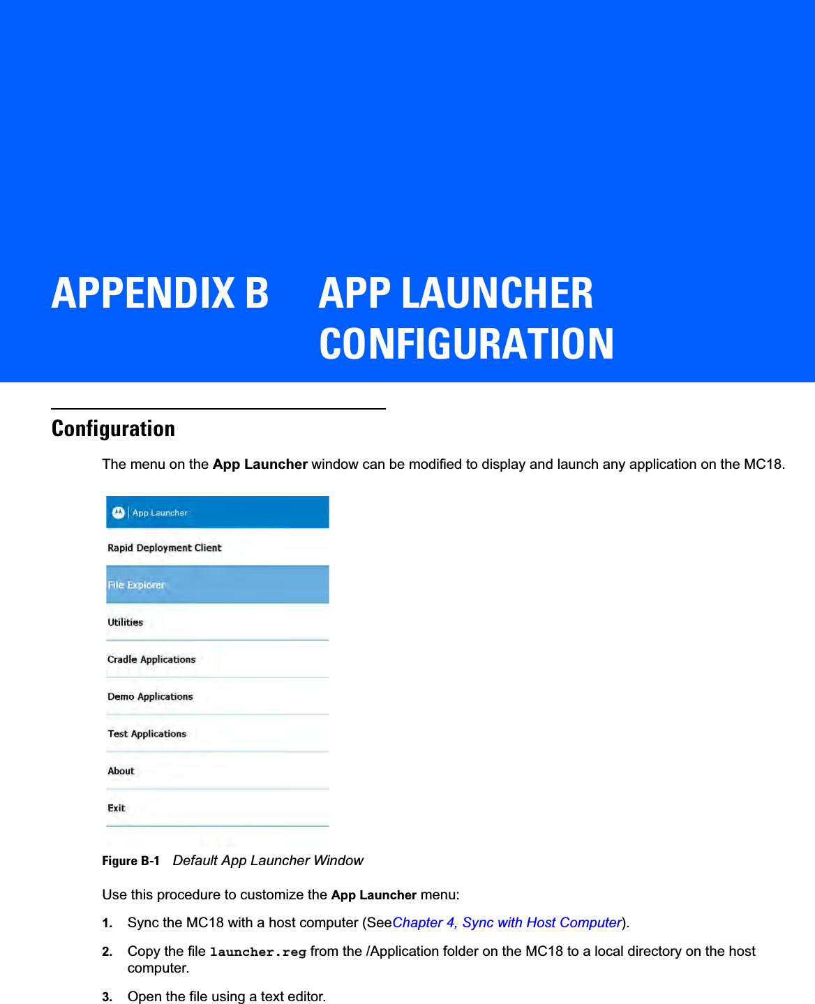
![B - 2 MC18 Product Reference Guide4. The following lists the five default menu items that appear on the App Launcher display. Note that Exit menu item is not listed in the registry file.[HKEY_CURRENT_USER\Software\Symbol\Launcher\Default\Programs\Prog1]"Description"="RD Client""Name"="\\windows\\rdclient.exe""Command"=""[HKEY_CURRENT_USER\Software\Motorola\AppLauncher\Profiles\DefaultProf\Default\Programs]"Description"="SPB""Name"="\\program files\\SPB2_CE.exe""Command"=""[HKEY_CURRENT_USER\Software\Symbol\Launcher\Default\Programs\Prog3]"Description"="Device Info""Name"="\\Windows\\DeviceInfoApp.exe""Command"=""[HKEY_CURRENT_USER\Software\Symbol\Launcher\Default\Programs\Prog4]"Description"="MC18-Scan""Name"="\\Application\\MC18-Scan.EXE""Command"=""[HKEY_CURRENT_USER\Software\Symbol\Launcher\Default\Programs\Prog5]"Description"="Reset""Name"="\\Windows\\WarmBoot.EXE""Command"=""Use this procedure to add a sixth item to the list, enter the following after the warm boot entry:[HKEY_CURRENT_USER\Software\Symbol\Launcher\Default\Programs\Prog6]"Description"="Control Panel""Name"="\\Windows\\CtlPanel.EXE""Command"=""1. Save the registry file.2. Copy the file back to the /Application folder on the MC18.3. Cold boot the MC18.](https://usermanual.wiki/Symbol-Technologies/MC18N0.User-Manual-rev-pdf/User-Guide-2620882-Page-150.png)