Symbol Technologies WSAP5100 WLAN Access Port User Manual AP300QIGver13 11x17
Symbol Technologies Inc WLAN Access Port AP300QIGver13 11x17
Contents
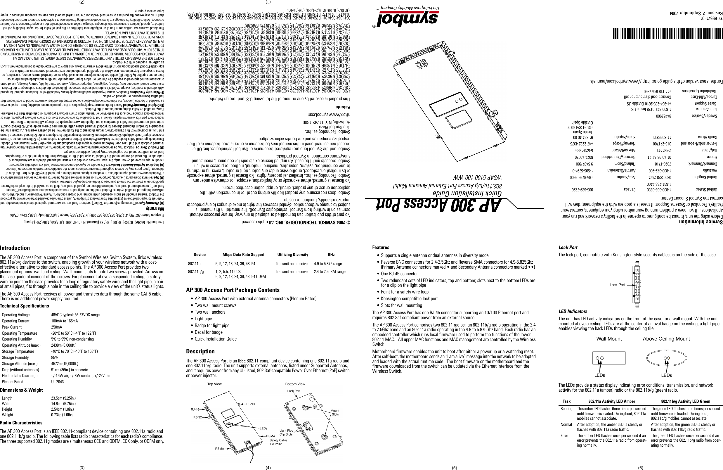
- 1. users manual 1
- 2. users manual 2
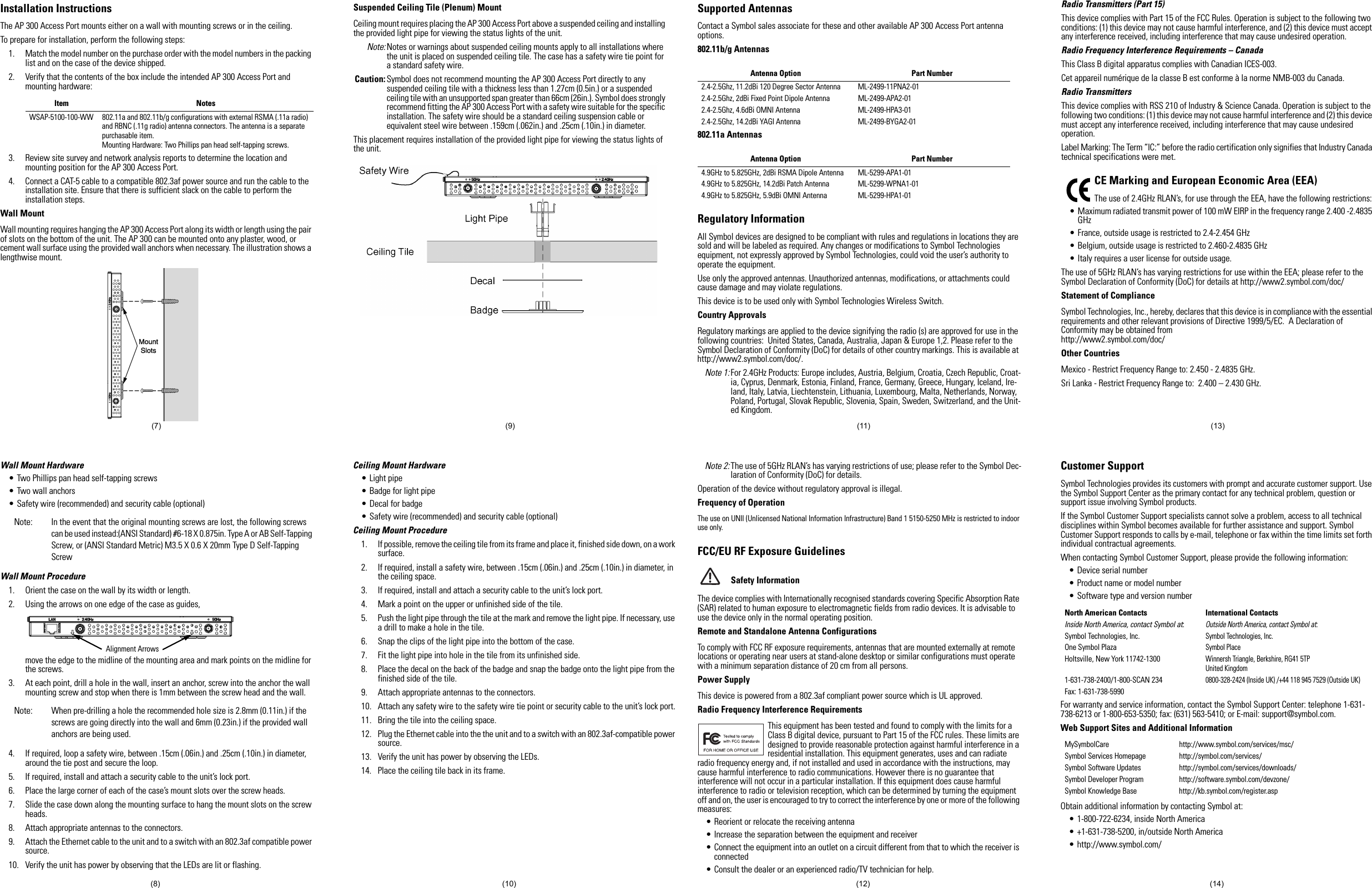
- 3. installation manual
- 4. revised users manual 1
- 5. revised users manual 2
revised users manual 2