Symbol Technologies WSAP5100 WLAN Access Port User Manual AP300QRG008
Symbol Technologies Inc WLAN Access Port AP300QRG008
Contents
users manual 1
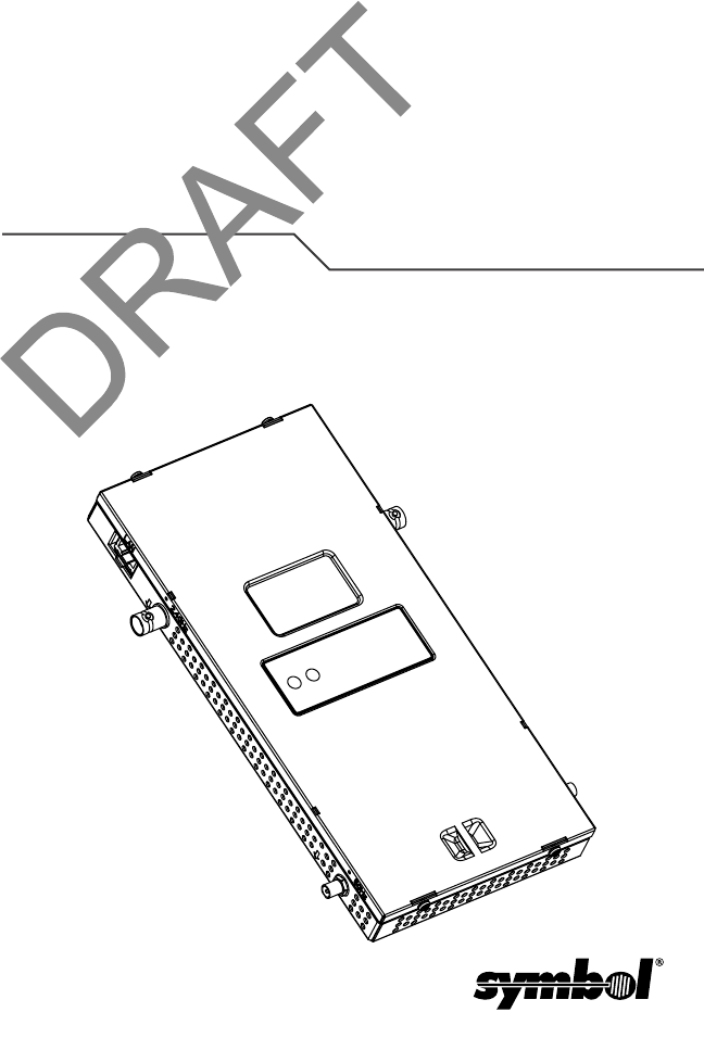
802.11a/b/g Access Port
External Antenna Model
Quick Reference Guide
AP 300

AP 300 Quick Reference Guide FINAL.Not for distribution.
Copyright
© 2004 SYMBOL TECHNOLOGIES, INC. All rights reserved.
All rights reserved. No part of this publication may be modified or adapted in any way, for any
purposes without permission in writing from Symbol Technologies, Inc. (Symbol). The material in
this manual is subject to change without notice. Symbol reserves the right to make changes to
any product to improve reliability, function, or design. No license is granted, either expressly or
by implication, estoppels, or otherwise under any Symbol Technologies, Inc., intellectual property
rights. An implied license only exists for equipment, circuits and subsystems contained in Symbol
products. Symbol, the Symbol logo and Spectrum24 are registered trademarks of Symbol
Technologies, Inc.
Patents
This product is covered by one or more of the following U.S. and foreign Patents:
U.S. Patent No. 4,593,186; 4,603,262; 4,607,156; 4,652,750; 4,673,805; 4,736,095;
4,758,717; 4,760,248; 4,806,742; 4,816,660; 4,845,350; 4,896,026; 4,897,532; 4,923,281;
4,933,538; 4,992,717; 5,015,833; 5,017,765; 5,021,641; 5,029,183; 5,047,617; 5,103,461;
5,113,445; 5,130,520; 5,140,144; 5,142,550; 5,149,950; 5,157,687; 5,168,148; 5,168,149;
5,180,904; 5,216,232; 5,229,591; 5,230,088; 5,235,167; 5,243,655; 5,247,162; 5,250,791;
5,250,792; 5,260,553; 5,262,627; 5,262,628; 5,266,787; 5,278,398; 5,280,162; 5,280,163;
5,280,164; 5,280,498; 5,304,786; 5,304,788; 5,306,900; 5,324,924; 5,337,361; 5,367,151;
5,373,148; 5,378,882; 5,396,053; 5,396,055; 5,399,846; 5,408,081; 5,410,139; 5,410,140;
5,412,198; 5,418,812; 5,420,411; 5,436,440; 5,444,231; 5,449,891; 5,449,893; 5,468,949;
5,471,042; 5,478,998; 5,479,000; 5,479,002; 5,479,441; 5,504,322; 5,519,577; 5,528,621;
5,532,469; 5,543,610; 5,545,889; 5,552,592; 5,557,093; 5,578,810; 5,581,070; 5,589,679;
5,589,680; 5,608,202; 5,612,531; 5,619,028; 5,627,359; 5,637,852; 5,664,229; 5,668,803;
5,675,139; 5,693,929; 5,698,835; 5,705,800; 5,714,746; 5,723,851; 5,734,152; 5,734,153;
5,742,043; 5,745,794; 5,754,587; 5,762,516; 5,763,863; 5,767,500; 5,789,728; 5,789,731;
5,808,287; 5,811,785; 5,811,787; 5,815,811; 5,821,519; 5,821,520; 5,823,812; 5,828,050;
5,848,064; 5,850,078; 5,861,615; 5,874,720; 5,875,415; 5,900,617; 5,902,989; 5,907,146;
5,912,450; 5,914,478; 5,917,173; 5,920,059; 5,923,025; 5,929,420; 5,945,658; 5,945,659;
5,946,194; 5,959,285; 6,002,918; 6,021,947; 6,029,894; 6,031,830; 6,036,098; 6,047,892;
6,050,491; 6,053,413; 6,056,200; 6,065,678; 6,067,297; 6,082,621; 6,084,528; 6,088,482;
6,092,725; 6,101,483; 6,102,293; 6,104,620; 6,114,712; 6,115,678; 6,119,944; 6,123,265;
6,131,814; 6,138,180; 6,142,379; 6,172,478; 6,176,428; 6,178,426; 6,186,400; 6,188,681;
6,209,788; 6,209,789; 6,216,951; 6,220,514; 6,243,447; 6,244,513; 6,247,647; 6,308,061;
6,250,551; 6,295,031; 6,308,061; 6,308,892; 6,321,990; 6,328,213; 6,330,244; 6,336,587;
6,340,114; 6,340,115; 6,340,119; 6,348,773; 6,380,949; 6,394,355; D305,885; D341,584;
D344,501; D359,483; D362,453; D363,700; D363,918; D370,478; D383,124; D391,250;
D405,077; D406,581; D414,171; D414,172; D418,500; D419,548; D423,468; D424,035;
D430,158; D430,159; D431,562; D436,104.
Invention No. 55,358; 62,539; 69,060; 69,187, NI-068564 (Taiwan); No. 1,601,796; 1,907,875;
1,955,269 (Japan); European Patent 367,299; 414,281; 367,300; 367,298; UK 2,072,832;
France 81/03938; Italy 1,138,713
rev. 06/02
Symbol Technologies, Inc.
One Symbol Plaza
Holtsville, N.Y. 11742-1300
http://www.symbol.com

1
FINAL.Not for distribution.
Introduction
The AP 300 Access Port, a component of the Symbol Wireless Switch
System, links wireless 802.11a/b/g devices to the switch, enabling
incremental growth of your wireless network with a cost-effective
alternative to standard access points. For optimal performance, the AP
300 provides two placement options: wall and ceiling. Wall mount slots
fit onto two screws provided. Arrows on the AP 300 case guide
placement of the screws. For placement above a suspended ceiling, a
safety cable tie point on the case provides for a loop of regulatory safety
cable, and the light pipe, a pair of small pipes, fits through a hole in the
ceiling tile to provide a view of the AP 300’s status lights.
The AP 300 receives all power and transfers data through the same
CAT-5 cable without any strain relief. There is no additional power
supply.
Technical Specifications
Dimensions & Weight
Operating Voltage 48VDC typical; 36-57VDC
range
Power Over Ethernet
Operating Current 100mA to 165mA
Peak Current 250mA
Operating
Temperature
-20°C to 50°C (-4°F to 122°F)
Operating Humidity 5% to 95% non-condensing
Storage Temperature -40°C to 70°C (-40°F to
158°F)
Storage Humidity 85%
Altitude 2438m (8,000ft.) maximum operating
4572m (15,000ft.) maximum storage
Drop 91cm (36in.) to concrete Without antenna modules
Electrostatic
Discharge
+/-15kV air; +/-8kV contact;
+/-2kV pin
Length 23.5cm (9.25in.)
Width 14.6cm (5.75in.)
Height 2.54cm (1.0in.)
Weight 0.73kg (1.6lbs)

2AP 300 Quick Reference Guide FINAL.Not for distribution.
Radio Characteristics
The AP 300 is an IEEE a/b/g-compliant device with the appropriate radio
option configured. The table below shows the characteristics for each
device compliance.
Package Contents
The AP 300 package contains the following items:
• AP 300 Access Port
• Two wide-shoulder screws
• Light pipe
• Badge for light pipe
• Decal for badge
Device Mbps Data Rate
Support
Utilizing
Diversity
GHz
802.11a 6, 9, 12, 18, 24, 36, 48,
and 54
Transmit and
receive
4.9 to 5.875 range
802.11g* 1.0, 2.0, 5.5, 6, 9, 12, 18,
24, 36, 48, and 54
Transmit and
receive
2.4 to 2.5 ISM range
*The supported 802.11g modes include either CCK only or OFDM only.
3
FINAL.Not for distribution.
Description
The AP 300 Access Port has two radios capable of concurrent 802.11a/
b/g radio configurations. The AP 300 external version supports external
antennas listed in Supported Antennas on page 9. The AP 300 takes
power from any 802.3af-compatible Power Over Ethernet (PoE) switch
or power injector.
Features
• Primary and secondary Reverse BNC connectors for 802.11b/g
antennas purchased separately
• Primary and secondary Reverse SMA connectors for 802.11a
antennas purchased separately
• One RJ-45 connector
• Two redundant sets of LED indicators, top and bottom; slots next to
the bottom LEDs are for a clip on the light pipe
• Point for a safety cable loop
• Kensington© Lock Port (not visible in views)
• Slots for wall mounting
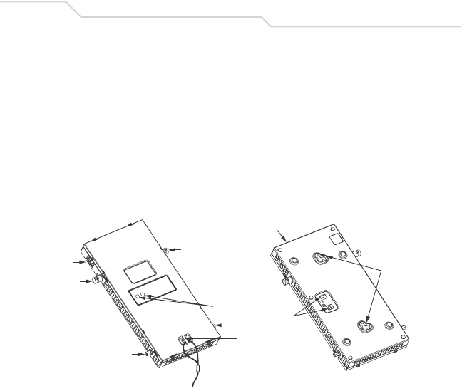
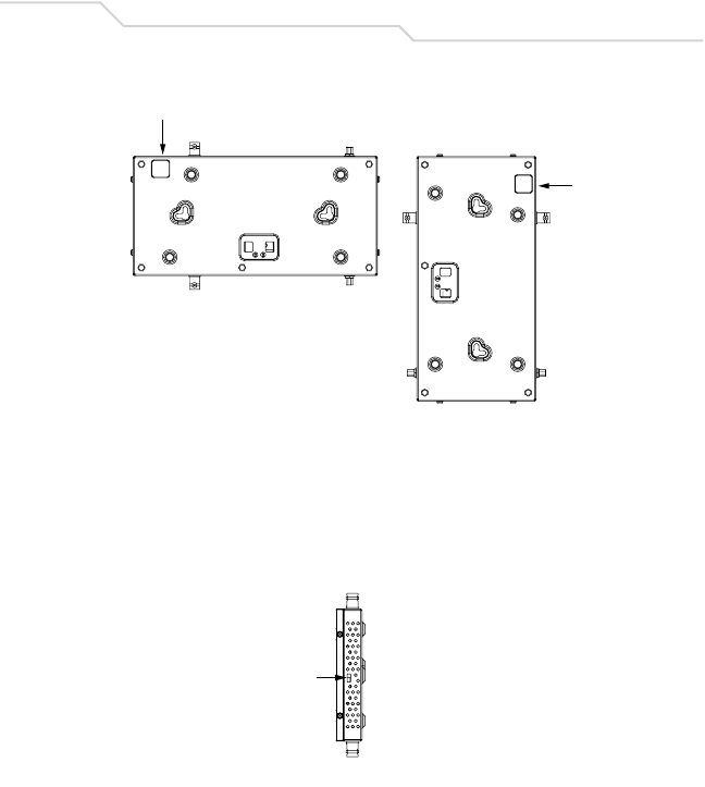
The AP 300 has one RJ-45 connector for a 10/100 Ethernet port, and
two pairs of antenna connectors: Reverse BNC for 2.4 to 2.5GHz and
Reverse SMA for 4.9 to 5.875GHz. The LAN port connects to a wireless
switch with a standard CAT-5 cable, straight through or cross-over,
without any strain relief.
Top View Bottom View
Lock Port
RJ-45
RBNC
RSMA
RBNC
RSMA
LEDs
Safety Cable
Tie Point
Mount
Slots
Light Pipe
Clip Slots
4AP 300 Quick Reference Guide FINAL.Not for distribution.
The AP 300 receives power through the Ethernet cable, optionally
connected to a Port Power Injector—for example, Symbol Model AP-
PSBIAS-T-12-AF Power Injector 12 Port. See the Symbol web site for
available PoE devices.
Review installation plans to determine device placement and cable
routing.
The AP 300 Access Port comprises two 802.11 radios: an 802.11b/g
radio operating in the 2.4 to 2.5Ghz band and an 802.11a radio operating
in the 4.9 to 5.875Ghz band. Each radio has an embedded controller
which runs local firmware used to perform the functions of the lower
802.11 MAC. All upper MAC functions and MAC management are
controlled by the Wireless Switch.
Motherboard firmware enables the AP 300 to boot after either a power
up or a watchdog reset. After self-boot, the motherboard sends an “I am
alive” message into the network to be adopted and loaded with the actual
runtime code. The boot firmware on the motherboard and the firmware
downloaded from the switch can be modified via the Ethernet interface
from either the Wireless Switch or by other Symbol diagnostic software
tools.
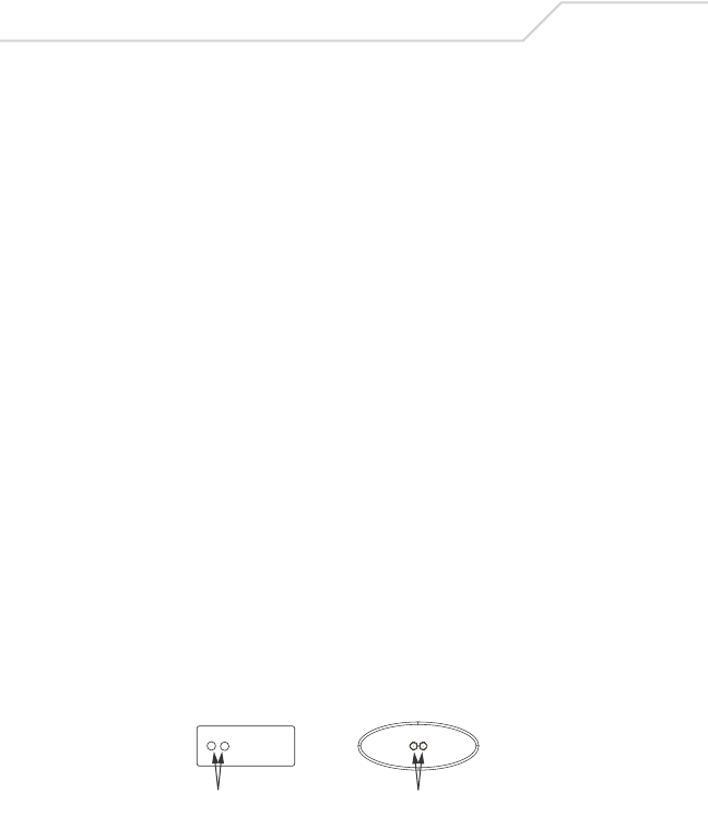
LED Indicators
The LED activity indicators appear on the top of the case for a wall
mount. With the unit mounted above a ceiling, the LEDs are at the center
of an oval badge on the ceiling; a light pipe enables the view through the
ceiling tile.
The LEDs provide a status display indicating error conditions,
transmission, and network activity for the 802.11a (amber) radio or the
802.11b/g (green) radio.
LEDs
LEDs
Above Ceiling MountWall Mount

5
FINAL.Not for distribution.
802.11a Activity LED Amber
802.11b/g Activity LED Green
Installation Instructions
The AP 300 mounts either on a wall with wide-shouldered screws
included or in the ceiling.
Before Beginning
Perform the following:
• Match the model number on the purchase order with the model
numbers in the packing list and on the case of the device shipped.
• Verify that the contents of the box include the intended AP 300 and
the mounting hardware:
• Review site survey and network analysis reports to determine the
location and mounting position for the AP 300.
Booting The amber LED flashes three times per second until firmware is
loaded. During boot, no 802.11a mobiles can associate.
Normal After adoption, the amber LED is steady or flashes with 802.11a radio
traffic.
Error The amber LED flashes once per second if an error prevents the
802.11a radio from operating normally.
Booting The green LED flashes three times per second until firmware is
loaded. During boot, no 802.11b/g mobiles can associate.
Normal After adoption, the green LED is steady or flashes with 802.11b/g
radio traffic.
Error The green LED flashes once per second if an error prevents the
802.11b/g radio from operating normally.
Item Notes
WSAP-5030-300-WW 802.11a and 802.11g configurations with external
RSMA (.11a radio) and RBNC (.11g radio) antenna
connectors. The antenna is a separate
purchasable item.
Mounting Hardware: Two wide-shoulder Phillips
pan head self-tapping screws.
6AP 300 Quick Reference Guide FINAL.Not for distribution.
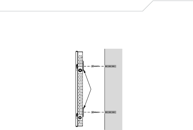
Wall Mounting
In this procedure, hang the AP 300 Access Port along its width or length
using the slots on the bottom of the unit. The following illustration shows
a lengthwise mount.
Hardware
• A CAT-5 cable connected to a compatible Symbol wireless
switch—for example, the WS 2000 or WS 5000—with sufficient
slack and without a molded or integrated strain relief on the
connector to the AP 300
• Two wide-shoulder Phillips pan head self-tapping screws
(provided)
• Case: In the procedure, use the arrows on the AP 300’s case as
a guide to determine the proper placement for the unit’s mounting
screws.
• Safety cable (recommended)
• Security cable (optional)
Procedure
1. Orient the case on the wall by its width or length.
Mount
Slots
7
FINAL.Not for distribution.
2. Using the arrows on the edge of the case as guides, move the
edge to the midline of the mounting area and mark points on the
midline for the screws.
3. At each point, screw in the self-tapping screws and stop where the
threads meet the shank or shoulder of the screw.
4. If required, install and attach a security cable to the unit’s lock port.
5. Place the large corner of each of the case’s mount slots over the
screw heads.
6. Slide the case down along the mounting surface to hang the
mount slots on the screw heads.
7. Attach the Ethernet cable.
8. Verify the unit has power by observing that the LEDs are lit or
flashing.
RJ-45
RJ-45
Lock Port

8AP 300 Quick Reference Guide FINAL.Not for distribution.
Suspended Ceiling Tile (Plenum) Mount
In this procedure, place the AP 300 above a suspended ceiling.
Note: Notes or warnings about suspended ceiling mounts apply to
all installations where the unit is placed on suspended ceiling
tile. The AP 300 case has a safety cable tie point for a
standard safety cable.
Caution: Symbol does not recommend mounting the AP 300 directly to
any suspended ceiling tile with a thickness less than 1.27cm
(0.5in.) or a suspended ceiling tile with an unsupported span
greater than 66cm (26in.). Symbol does strongly recommend
fitting the AP 300 with a safety cable suitable for the specific
installation. The safety cable should be steel—a steel wire
rope to the standard ceiling suspension cable—and in
diameter at least .159cm (.062in.) to .25cm (.10in.).
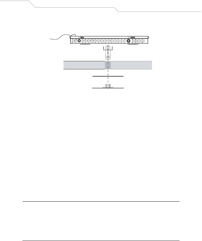
This placement requires installation of the provided light pipe for viewing
the status lights of the unit.
Hardware
• A CAT-5 cable connected to a compatible Symbol wireless
switch—for example, the WS 2000 or WS 5000—with sufficient
slack—optimally, to reach a work surface from the ceiling
• Light pipe
• Badge for light pipe
• Decal for badge
• Safety cable (recommended)
• Security cable (optional)
Procedure
1. If possible, remove the ceiling tile from its frame and place it,
finished side down, on a work surface.
2. If required, install in the ceiling space the recommended safety
cable—steel at least .15cm (.06in.) to .25cm (.10in.) in diameter—
and a security cable.
3. Mark a point on the upper or unfinished side of the tile.
4. Push the lightpipe through the tile at the mark. If necessary, use a
drill to make a hole in the tile.
9
FINAL.Not for distribution.
5. Snap the clips of the light pipe into the bottom of the case.
6. Fit the light pipe into hole in the tile from its unfinished side.
7. Place the decal on the back of the badge and snap the badge onto
the light pipe from the finished side of the tile.
8. Bring the tile into the ceiling space, and attach any safety cable to
the safety cable tie point or security cable to the unit’s lock port.
9. Plug the Ethernet cable into the LAN port.
10. Verify the unit has power by observing the LEDs.
11. Place the ceiling tile back in its frame.
Supported Antennas
Contact a Symbol sales associate for these and other available AP 300
antenna options.
802.11b/g Antennas
802.11a Antennas
Antenna Option Part Number
2.4-2.5Ghz, 11 dBi 120 Degree Sector Antenna ML-2499-11PNA2-01
2.4-2.5Ghz, 3.5 dBi Fixed Point Dipole Antenna ML-2499-APA2-01
2.4-2.5Ghz, 5 dBi OMNI Antenna ML-2499-HPA3-01
2.4-2.5Ghz, 14 dBi YAGI Antenna ML-2499-BYGA2-01
Antenna Option Part Number
5.15GHz to 5.825GHz, 2Bi RSMA Dipole Antenna ML-5299-APA1-01
5.15GHz to 5.825GHz, 13Bi Patch Antenna ML-5299-WPNA1-01
5.15GHz to 5.825GHz, 5Bi OMNI Antenna ML-5299-HPA1-01
Badge
Decal
Ceiling Tile
Light Pipe
Safety Cable

10 AP 300 Quick Reference Guide FINAL.Not for distribution.
Customer Support
Symbol Technologies provides its customers with prompt and accurate
customer support. Use the Symbol Support Center as the primary
contact for any technical problem, question or support issue involving
Symbol products.
If the Symbol Customer Support specialists cannot solve a problem,
access to all technical disciplines within Symbol becomes available for
further assistance and support. Symbol Customer Support responds to
calls by e-mail, telephone or fax within the time limits set forth individual
contractual agreements.
When contacting Symbol Customer Support, please provide the
following information:
• Device serial number
• Product name or model number
• Software type and version number
North American Contacts
Inside North America, contact Symbol at:
Symbol Technologies, Inc.
One Symbol Plaza
Holtsville, New York 11742-1300
Telephone: 1-631-738-2400/1-800-SCAN 234
Fax: 1-631-738-5990
Symbol Support Center (for warranty and service information):
Telephone: 1-631-738-6213/1-800-653-5350
Fax: (631) 563-5410
E-mail: support@symbol.com
International Contacts
Outside North America, contact Symbol at:
Symbol Technologies, Inc.
Symbol Place
Winnersh Triangle, Berkshire, RG41 5TP
United Kingdom
0800-328-2424 (Inside UK)
+44 118 945 7529 (Outside UK)

11
FINAL.Not for distribution.
Web Support Sites
MySymbolCare
http://www.symbol.com/services/msc
Symbol Services Homepage
http://symbol.com/services
Symbol Software Updates
http://symbol.com/services/downloads
Symbol Developer Program
http://software.symbol.com/devzone
Symbol Knowledge Base
http://kb.symbol.com/register.asp
Additional Information
Obtain additional information by contacting Symbol at:
• 1-800-722-6234, inside North America
• +1-631-738-5200, in/outside North America
• http://www.symbol.com/

12 AP 300 Quick Reference Guide FINAL.Not for distribution.
Legal Information
Regulatory
All Symbol devices are designed to be compliant with rules and regulations in
locations they are sold and will be labeled as required.
Any changes or modifications to Symbol Technologies equipment, not expressly
approved by Symbol Technologies, could void the user's authority to operate the
equipment.
Use only the supplied or an approved replacement antenna. Unauthorized
antennas, modifications, or attachments could cause damage and may violate
regulations.
This device is to be used only with Symbol Technologies Wireless Switch.
Applying the Regulatory Country Stamp
Regulatory labels are applied to the device signifying the radio(s) are approved for
use in the following countries: United States, Canada, Australia, Japan & Europe
1,2.
Note 1: For 2.4GHz Products: Europe includes, Austria, Belgium, Croatia,
Denmark, Estonia, Finland, France, Germany, Greece, Iceland, Ire-
land, Italy, Liechtenstein, Luxembourg, Netherlands, Norway, Portu-
gal, Spain, Sweden, Switzerland, United Kingdom.
Note 2: The use of 5GHz RLAN's has varying restrictions of use; please re-
fer to the Symbol Declaration of Conformity (DoC) for details at http:/
/www2.symbol.com/doc/.
In addition to the list above other countries may require a regulatory stamp to be
affixed to the product.
Please refer to www.symbol.com/ for the list of countries where mandatory stamps
are required.
For countries that require regulatory label, a sheet of stamps may be enclosed
within the package.
If the appropriate stamps are not provided, please contact your supplier.
To apply the country stamp:
1. Peel the stamp appropriate to the country where this device is to be used.
2. Apply the country stamp in the space provided on the regulatory label.
Caution: Operation of the device without a regulatory label or the correct country
Stamp is illegal.
13
FINAL.Not for distribution.
FCC RF Exposure Guidelines
Safety Information
Caution: The device complies with internationally recognized standards
covering Specific Absorption Rate (SAR) related to human exposure to
electromagnetic fields from radio devices.
It is advisable to use the device only in the normal operating position.
Remote and Standalone Antenna Configurations.
To comply with FCC RF exposure requirements, antennas that are mounted
externally at remote locations or operating near users at stand-alone desktops of
similar configurations must operate with a minimum separation distance of 20cm
from all persons.
Radio Frequency Interference Requirements
This equipment has been tested and found
to comply with the limits for a Class B digital
device, pursuant to Part 15 of the FCC
rules. These limits are designed to provide
reasonable protection against harmful
interference in a residential installation.
This equipment generates, uses and can
radiate radio frequency energy and, if not installed and used in accordance with the
instructions, may cause harmful interference to radio communications.
However there is no guarantee that interference will not occur in a particular
installation.
If this equipment does cause harmful interference to radio or television reception,
which can be determined by turning the equipment off and on, the user is
encouraged to try to correct the interference by one or more of the following
measures:
• Reorient or relocate the receiving antenna
• Increase the separation between the equipment and receiver
• Connect the equipment into an outlet on a circuit different from that to which
the receiver is connected
• Consult the dealer or an experienced radio/TV technician for help.
Radio Transmitters (Part 15)
This device complies with Part 15 of the FCC Rules. Operation is subject to the
following two conditions: (1) this device may not cause harmful interference, and
(2) this device must accept any interference received, including interference that
may cause undesired operation.
Radio Frequency Interference Requirements - Canada
This Class B digital apparatus complies with Canadian ICES-003.
Cet appareil numérique de la classe B est conforme à la norme NMB-003 du
Canada.

14 AP 300 Quick Reference Guide FINAL.Not for distribution.
Radio Transmitters
This device complies with RSS 210 of Industry & Science Canada.
Operation is subject to the following two conditions: (1) this device may
not cause harmful interference and (2) this device must accept any
interference received, including interference that may cause undesired
operation.
Label Marking: The Term "IC:" before the radio certification only signifies
that Industry Canada technical specifications were met.
Marking and European Economic Area (EEA)
The use of 2.4GHz RLANs, for use in the EEA, have the following restrictions:
• In the range of 2.400GHz -2.4835GHz, the maximum radiated transmit power
is 100mW EIRP.
• In France, the equipment is restricted to the range 2.4465GHz to 2.4835GHz.
• For Belgium outside usage, the equipment is restricted to the range
2.460GHz to 2.4835GHz.
• Italy requires a user license for outside usage.
The use of 5GHz RLANs has varying restrictions for use within the EEA; please
refer to the Symbol Declaration of Conformity (DoC), details at
http://www2.symbol.com/doc/
Statement of Compliance
Symbol Technologies, Inc., hereby, declares that this device is in compliance with
the essential requirements and other relevant provisions of Directive 1999/5/EC.
A Declaration of Conformity may be obtained from http://www2.symbol.com/doc/.
Other Countries
Mexico–Restrict Frequency Range to: 2.450GHz - 2.4835GHz.
Israel–Restrict Frequency Range to: 2.418GHz - 2.457GHz.
Sri Lanka–Restrict Frequency Range to: 2.400GHz - 2.430GHz.
Tested to Comply With FCC Standards
For Home or Office Use
Symbol Technologies Inc.