Symbol Technologies WSM5030 RLAN Radio Module User Manual 72 61070 01B Draft Page 1
Symbol Technologies Inc RLAN Radio Module 72 61070 01B Draft Page 1
Contents
- 1. Quick Reference Guide
- 2. Amendment letter
- 3. Module Installation
Module Installation
Introduction
The AP 200 Access Port provides 802.11a/b coverage to wireless network devices. The AP
200 allows the use of internal or external antenna options.
Three base models of the AP 200 are available. Accessory options are available for each con-
figuration (when applicable) and include:
802.11a Internal Antenna
802.11b Internal Antenna with Radio
802.11b External Antenna with Radio
Technical Specifications
Specifications only apply to the AP 200 Access Port assembly.
Operating Voltage 48VDC (typical); 36VDC to 57VDC (range)
Operating Current 10mA to 150mA
Peak Current 250mA
Operating Temperature -20°C to 50°C (-4°F to 122°F)
Operating Humidity 5% to 85% non-condensing
Storage Temperature -40°C to 70°C (-40°F to 158°F)
Storage Humidity 85%
Altitude 2438m (8,000ft.) (operating max)
4572m (15,000ft.) (storage max)
Drop: No antenna modules) 91cm (36in.) to concrete
With antenna modules 76cm (30in.) to concrete
Electrostatic Discharge +/-15KV (air discharge); +/-8KV (contact discharge);
+/-2KV (pin discharge)
Radio Characteristics
The AP 200 is an IEEE 802.11a/b compliant device when configured with the appropriate radio
option.
As an IEEE 802.11a device it supports 6, 9, 12, 18, 24, 36, 48 and 54Mbps data rates, utilizing
transmit-only diversity, in the 5.15GHz to 5.825GHz range.
As an IEEE 802.11b device it supports 1.0, 2.0, 5.5 and 11.0Mbps data rates, utilizing transmit
and receive diversity, in the 2.4GHz to 2.5GHz ISM radio band.
Installation of Optional Accessory Hardware
The available radio/antenna options vary depending on the AP 200 configuration purchased.
Note: A tamper resistant #10 Torx driver is required to remove and install antenna modules
(internal/external). This tool is not included with the AP 200 or antenna/radio options, but, is
available in the open market.
Caution! This equipment contains components that can be damaged by electrostatic
discharge. When handling radio/antenna options use proper electrostatic safety handling
procedures. Ensure all power and data cables are removed before installing any radio options.
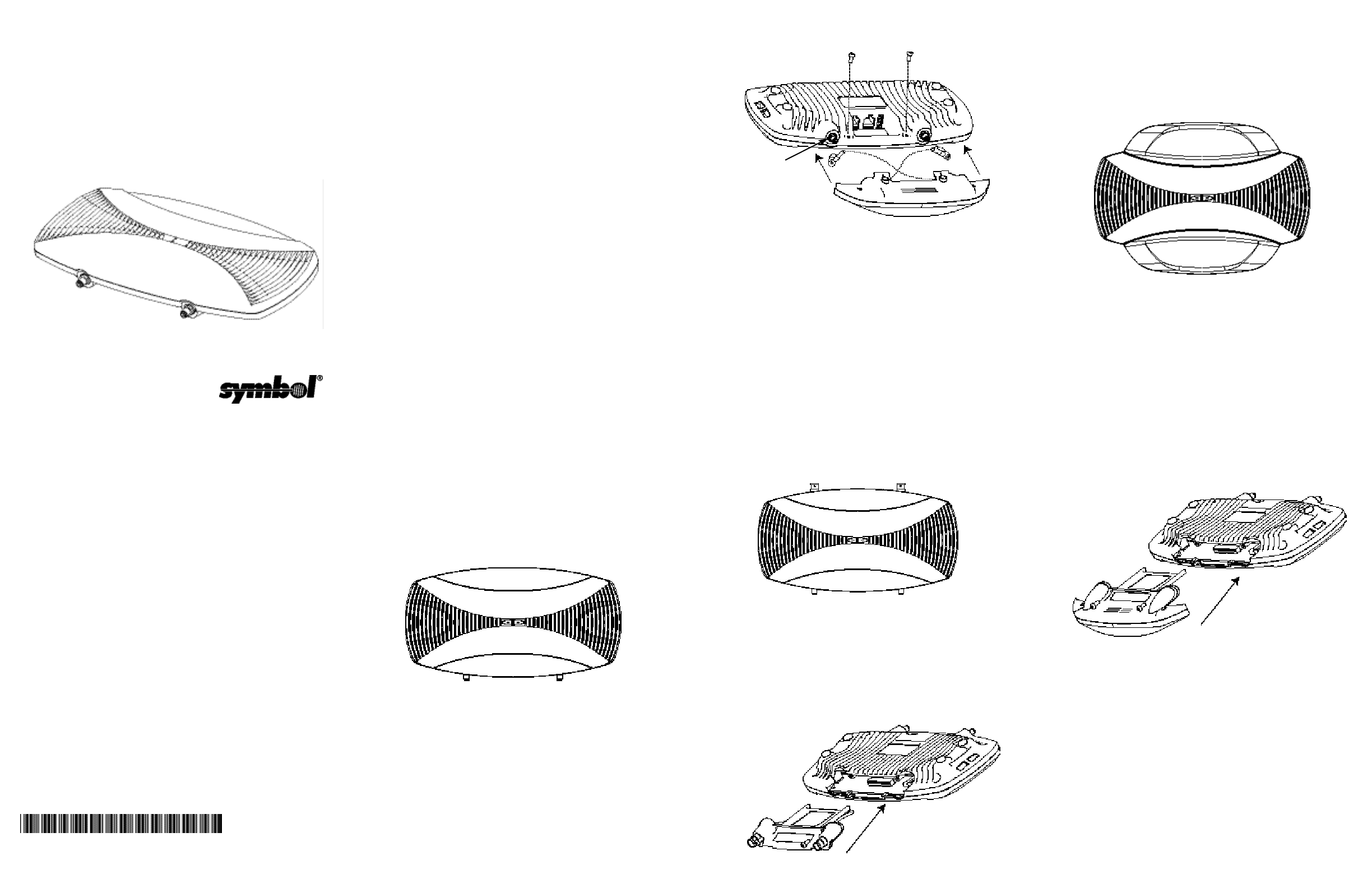
802.11a Internal Antenna Option
Note: Removing and installing antenna option with the AP 200 upside down (ribbed side up) is
recommended.
1. Ensure the AP 200 is on a level work area such as a table and not mounted to any surface.
2. Remove the internal antenna and tamper resistant screws from the shipping container and
remove any packaging material.
3. The Internal 802.11a antenna contains two coaxial cables with reverse SMA connectors
that connect to the external antenna connectors on the main unit. The internal antenna
housing has a pin, that mates to a micro switch, on the main housing, near the external
antenna connectors. Properly seating the internal antenna so the pin makes good contact
is necessary, so the AP 200 can sense that an internal Antenna is in use.
4. Ensure the coaxial cables cross over each other before connecting to the external connec-
tors. This allows the internal antenna cables to tuck neatly inside the antenna housing
when secured to the AP 200.
5. Connect the internal antenna to the 802.11a AP 200 using the two coaxial reverse SMA
connector plugs.
Note: Ensure the 802.11a antenna cables are crossed over each other before connecting
to the AP 200 external antenna connectors and securing the antenna housing to the
AP 200.
6. Holding the internal antenna unit level to the AP 200 carefully mount the antenna onto the
AP 200 (ensure the antenna cables stay tucked into the housing) until it is flush with the
main housing.
7. Using the torx tool and screws (2) secure the antenna to the AP 200.
8. Verify the unit has power by observing the Amber LED.
802.11b External Antenna Radio Option
Caution! This equipment contains components that can be damaged by electrostatic
discharge. When handling radio/antenna options use proper electrostatic safety handling
procedures. Ensure all power and data cables are removed before installing any radio options.
Note: Removing and installing antenna option with the AP 200 upside down (ribbed side up) is
recommended.
1. Ensure the AP 200 is not mounted to any surface and is on a level work area such as a
table.
2. Remove the 802.11b external antenna radio option and tamper resistant screws from the
shipping container and remove any packaging material.
3. Using the torx tool remove the access panel (if the internal antenna option is installed,
remove it) covering the 802.11b side of the AP 200. Discard the access panel.
4. Carefully hold and align the 802.11b external antenna radio option slide rails with the AP
200 card slot (if the AP 200 is upside down, place the antenna/radio PCI card face down as
it is aligned and inserted).
5. Insert into the AP 200 until it is flush with the main housing.
6. Using the Torx tool and screws, secure the external antenna radio option to the AP 200.
7. Verify the unit has power by observing the Amber LED.
Note: Refer to the WS 5000 Wireless Switch Online System Reference guide included with
the switch hardware for configuration of the AP 200.
802.11b Internal Antenna Radio Option
Caution! This equipment contains components that can be damaged by electrostatic
discharge. When handling radio/antenna options use proper electrostatic safety handling
procedures. Ensure all power and data cables are removed before installing any radio options.
Note: Removing and installing antenna option with the AP 200 upside down (ribbed side up) is
recommended.
1. Ensure the AP 200 is not mounted to any surface and is on a level work area such as a
table.
2. Remove the 802.11b internal antenna radio option and tamper resistant screws from the
shipping container and remove any packaging material.
3. Using the torx tool to remove the access panel (if the external antenna/radio option is
installed, remove it) covering the 802.11b side of the AP 200.
4. Carefully hold and align the 802.11b internal antenna/radio option slide rails with the AP
200 card slot (if the AP 200 is upside down, place the antenna/radio PCI card face down as
it is aligned and inserted).
5. Insert into the AP 200 until it is flush with the main housing.
6. Using the Torx tool and screws, secure the external antenna radio option to the AP 200.
7. Verify the unit has power by observing the Amber LED.
Note: Refer to the WS 5000 Wireless Switch Online System Reference guide included with
the switch hardware for configuration of the AP 200.
AP 200
802.11a/b Access Port
Accessories Addendum
www.symbol.com
Copyright
Copyright © 2003 by Symbol Technologies, Inc. All rights reserved. No part of this publication may be modi-
fied or adapted in any way, for any purposes without permission in writing from Symbol Technologies, Inc.
(Symbol). The material in this manual is subject to change without notice. Symbol reserves the right to make
changes to any product to improve reliability, function, or design. No license is granted, either expressly or by
implication, estoppels, or otherwise under any Symbol Technologies, Inc., intellectual property rights. An
implied license only exists for equipment, circuits and subsystems contained in Symbol products. Symbol, the
Symbol logo and Spectrum24 are registered trademarks of Symbol Technologies, Inc.
Patents
This product is covered by one or more of the following U.S. and foreign Patents:
U.S. Patent No.
4,460,120; 4,496,831; 4,593,186; 4,603,262; 4,607,156; 4,652,750; 4,673,805; 4,736,095; 4,758,717;
4,816,660; 4,845,350; 4,896,026; 4,897,532; 4,923,281; 4,933,538; 4,992,717; 5,015,833; 5,017,765;
5,021,641; 5,029,183; 5,047,617; 5,103,461; 5,113,445; 5,130,520; 5,140,144; 5,142,550; 5,149,950;
5,157,687; 5,168,148; 5,168,149; 5,180,904; 5,216,232; 5,229,591; 5,230,088; 5,235,167; 5,243,655;
5,247,162; 5,250,791; 5,250,792; 5,260,553; 5,262,627; 5,262,628; 5,266,787; 5,278,398; 5,280,162;
5,280,163; 5,280,164; 5,280,498; 5,304,786; 5,304,788; 5,306,900; 5,321,246; 5,324,924; 5,337,361;
5,367,151; 5,373,148; 5,378,882; 5,396,053; 5,396,055; 5,399,846; 5,408,081; 5,410,139; 5,410,140;
5,412,198; 5,418,812; 5,420,411; 5,436,440; 5,444,231; 5,449,891; 5,449,893; 5,468,949; 5,471,042;
5,478,998; 5,479,000; 5,479,002; 5,479,441; 5,504,322; 5,519,577; 5,528,621; 5,532,469; 5,543,610;
5,545,889; 5,552,592; 5,557,093; 5,578,810; 5,581,070; 5,589,679; 5,589,680; 5,608,202; 5,612,531;
5,619,028; 5,627,359; 5,637,852; 5,664,229; 5,668,803; 5,675,139; 5,693,929; 5,698,835; 5,705,800;
5,714,746; 5,723,851; 5,734,152; 5,734,153; 5,742,043; 5,745,794; 5,754,587; 5,762,516; 5,763,863;
5,767,500; 5,789,728; 5,789,731; 5,808,287; 5,811,785; 5,811,787; 5,815,811; 5,821,519; 5,821,520;
5,823,812; 5,828,050; 5,850,078; 5,861,615; 5,874,720; 5,875,415; 5,900,617; 5,902,989; 5,907,146;
5,912,450; 5,914,478; 5,917,173; 5,920,059; 5,923,025; 5,929,420; 5,945,658; 5,945,659; 5,946,194;
5,959,285; 6,002,918; 6,021,947; 6,047,892; 6,050,491; 6,053,413; 6,056,200; 6,065,678; 6,067,297;
6,068,190; 6,082,621; 6,084,528; 6,088,482; 6,092,725; 6,101,483; 6,102,293; 6,104,620; 6,114,712;
6,115,678; 6,119,944; 6,123,265; 6,131,814; 6,138,180; 6,142,379; D305,885; D341,584; D344,501;
D359,483; D362,453; D363,700; D363,918; D370,478; D383,124; D391,250; D405,077; D406,581;
D414,171; D414,172; D418,500; D419,548; D423,468; D424,035; D430,158; D430,159; D431,562
Invention No. 55,358; 62,539; 69,060; 69,187 (Taiwan); No. 1,601,796; 1,907,875; 1,955,269 (Japan);
European Patent 367,299; 414,281; 367,300; 367,298; UK 2,072,832; France 81/0938; Italy 1,138,713
3/02
Symbol Technologies, Inc.
One Symbol Plaza
Holtsville, NY
11742-1300
http://www.symbol.com
72-61070-01
Rev.Draft (1) (2) (3)
Integral Antenna
Micro Switch
Available Options
Contact a Symbol sales associate for available AP 200 radio and antenna options.
Radio or Antenna Part number Notes
Option
.11a Internal antenna WSM-5040-110-WW Requires a special removal/installation
tool available in the open market. Not
supplied by Symbol Technologies.
.11a External RSMA ML-5299-APA1-01
Dipole antenna
.11b radio with external WSM-5030-200-WW Requires a special removal/installation
antenna connectors tool available in the open market. Not
supplied by Symbol Technologies.
.11b radio with internal WSM-5030-210-WW Requires a special removal/installation
antenna tool available in the open market. Not
supplied by Symbol Technologies.
.11b External RBNC ML 2499-APA1-00
dipole antenna
.11b External RBNC ML 2499-HPA1-00
high performance
single antenna
.11b Twin high ML 2499-DVA1-00
performance
diversity antennas
.11b Mountable 48-450115-01
F-plane antenna
Note: A tamper resistant #10 Torx driver is required to remove and install antenna modules
(internal/external). This tool is not included with the AP 200 or antenna/radio options, but, is
available in the open market.
Customer Support
Symbol Technologies provides its customers with prompt and accurate customer support. Use
the Symbol Support Center as the primary contact for any technical problem, question or sup-
port issue involving Symbol products.
If the Symbol Customer Support specialists cannot solve a problem, access to all technical
disciplines within Symbol becomes available for further assistance and support. Symbol
Customer Support responds to calls by email, telephone or fax within the time limits set forth in
individual contractual agreements.
When contacting Symbol Customer Support, please provide the following information:
•Device serial number
•Product name or model number
•Software type and version number.
North American Contacts
Inside North America, contact Symbol at:
Symbol Technologies, Inc.
One Symbol Plaza
Holtsville, New York 11742-1300
Telephone: 1-631-738-2400/1-800-SCAN 234
Fax: 1-631-738-5990
Symbol Support Center (for warranty and service information):
Telephone: 1-631-738-6213/1-800-653-5350
Fax: (631) 563-5410
Email: support@symbol.com
International Contacts
Outside North America, contact Symbol at:
Symbol Technologies, Inc.
Symbol Place
Winnersh Triangle, Berkshire, RG41 5TP
United Kingdom
0800-328-2424 (Inside UK)
+44 118 945 7529 (Outside UK)
Web Support sites
MySymbolCare
http://www.symbol.com/services/msc
Symbol Services Homepage
http://www.symbol.com/services
Symbol Software Updates
http://www.symbol.com/services/downloads
Symbol Developer Program
http://devzone.symbol.com
Symbol Knowledge Base
http://kb.symbol.com/register.asp
Additional Information
Obtain additional information by contacting Symbol at:
•1-800-722-6234, inside North America
•+1-631-738-5200, in/outside North America
•http://www.symbol.com/
Legal Information
Regulatory Information
All Symbol devices are designed to be compliant with rules and regulations in locations they
are sold and will be labeled as required.
Any changes or modifications to Symbol Technologies equipment, not expressly approved by
Symbol Technologies, could void the user's authority to operate the equipment.
Use only the supplied or an approved replacement antenna. Unauthorized antennas,
modifications, or attachments could cause damage and may violate regulations.
This Device is to be used only with Symbol Technologies Wireless Switch.
Applying the Regulatory Country Stamp
Regulatory labels are applied to the device signifying the radio(s) are approved for use in the
following countries: United States, Canada, Australia, Japan & Europe 1,2.
Note 1: For 2.4GHz Products: Europe includes, Austria, Belgium, Croatia, Denmark, Estonia,
Finland, France, Germany, Greece, Iceland, Ireland, Italy, Liechtenstein, Luxembourg,
Netherlands, Norway, Portugal, Spain, Sweden, Switzerland, United Kingdom.
Note 2: The use of 5GHz RLAN's has varying restrictions of use; please refer to the Symbol
Declaration of Conformity (DoC) for details at http://www2.symbol.com/doc/
In addition to the list above other countries may require a regulatory stamp to be affixed to
the product.
Please refer to www.symbol.com/ for the list of countries where mandatory stamps
are required.
For countries that require regulatory label, a sheet of stamps may be enclosed within the
package.
If the appropriate stamps are not provided, please contact your supplier.
To apply the country stamp:
1. Peel the stamp appropriate to the country where this device is to be used.
2. Apply the country stamp in the space provided on the regulatory label.
Operation of the device without a regulatory label or the correct country Stamp
is illegal.
FCC RF Exposure Guidelines
Safety Information
The device complies with internationally recognized standards covering Specific
Absorption Rate (SAR) related to human exposure to electromagnetic fields from radio
devices.
It is advisable to use the device only in the normal operating position.
Remote and Standalone Antenna Configurations
To comply with FCC RF exposure requirements, antennas that are mounted externally at
remote locations or operating near users at stand-alone desktops of similar configurations
must operate with a minimum separation distance of 20 cm from all persons.
Power Supply
Use only Symbol approved power supplies 50-24000-049 output rated 48VDC and minimum
1.1amp or 50-24000-050 output rated 48VDC and minimum .25amp. The power supply is cer-
tified to EN60950 with SELV outputs. Use of alternative power supply will invalidate any
approval given to this device and may be dangerous.
Hinweis: Benutzen Sie nur eine Symbol Technologies genehmigt Stromversorgung
50-24000-049 in den Ausgabe: 48Vdc und minimum 1.1A. oder 50-24000-050 in den
Ausgabe: 48VDC und minimum .25A. Die Stromversorgung ist bescheinigt nach EN60950 mit
SELV Ausgaben
•Model 50-24000-049 48VDC power supply
•Model 50-24000-050 48VDC power supply
•Model AP-PSBIAS-T-12-AF Power Injector-12 Port
Radio Frequency Interference Requirements
This equipment has been tested and found to
comply with the limits for a Class B digital device,
pursuant to Part 15 of the FCC rules. These limits
are designed to provide reasonable protection
against harmful interference in a residential instal-
lation. This equipment generates, uses and can
radiate radio frequency energy and, if not installed
and used in accordance with the instructions, may cause harmful interference to radio commu-
nications. However there is no guarantee that interference will not occur in a particular installa-
tion. If this equipment does cause harmful interference to radio or television reception, which
can be determined by turning the equipment off and on, the user is encouraged to try to cor-
rect the interference by one or more of the following measures:
•Reorient or relocate the receiving antenna
•Increase the separation between the equipment and receiver
•Connect the equipment into an outlet on a circuit different from that to which the receiver is
connected
•Consult the dealer or an experienced radio/TV technician for help.
Radio Transmitters (Part 15)
This device complies with Part 15 of the FCC Rules. Operation is subject to the following two
conditions: (1) this device may not cause harmful interference, and (2) this device must accept
any interference received, including interference that may cause undesired operation.
Radio Frequency Interference Requirements - Canada
This Class B digital apparatus complies with Canadian ICES-003.
Cet appareil numérique de la classe B est conforme à la norme NMB-003 du Canada.
Radio Transmitters
This device complies with RSS 210 of Industry & Science Canada. Operation is subject to the
following two conditions: (1) this device may not cause harmful interference and (2) this device
must accept any interference received, including interference that may cause undesirable
operation.
Label Marking: The Term "IC:" before the radio certification only signifies that Industry Canada
technical specifications were met.
Marking and European Economic Area (EEA)
The use of 2.4GHz RLAN's, for use through the EEA, have the following restrictions:
•Maximum radiated transmit power of 100 mW EIRP in the frequency range
2.400GHz -2.4835GHz
•France, equipment is restricted to 2.4465GHz -2.4835GHz frequency range
•Belgium outside usage, the equipment is restricted to 2.460GHz -2.4835GHz frequency
range
•Italy requires a user license for outside usage.
The use of 5GHz RLAN's has varying restrictions for use within the EEA; please refer to the
Symbol Declaration of Conformity (DoC) for details at http://www2.symbol.com/doc/
Statement of Compliance
Symbol Technologies, Inc., hereby, declares that this device is in compliance with the essential
requirements and other relevant provisions of Directive 1999/5/EC. A Declaration of Conformity
may be obtained from http://www2.symbol.com/doc/
Other Countries
Mexico - Restrict Frequency Range to: 2.450GHz - 2.4835GHz.
Israel - Restrict Frequency Range to: 2.418GHz - 2.457GHz.
Sri Lanka - Restrict Frequency Range to: 2.400GHz - 2.430GHz.
(4) (5) (7)
(6)