Sysgration SY-SHE-M-001 BLE Mesh Module User Manual CSR1012 BLE Module PRD ForFCC V0 5 20150903
Sysgration Ltd. BLE Mesh Module CSR1012 BLE Module PRD ForFCC V0 5 20150903
UserManual.wiki
>
Sysgration
>
SY SHE M 001 User Manual
Users Manual
Navigation menu
Upload a User Manual
Namespaces
Wiki Guide
HTML
PDF
Info
Views
User Manual
Discussion / Help
Navigation
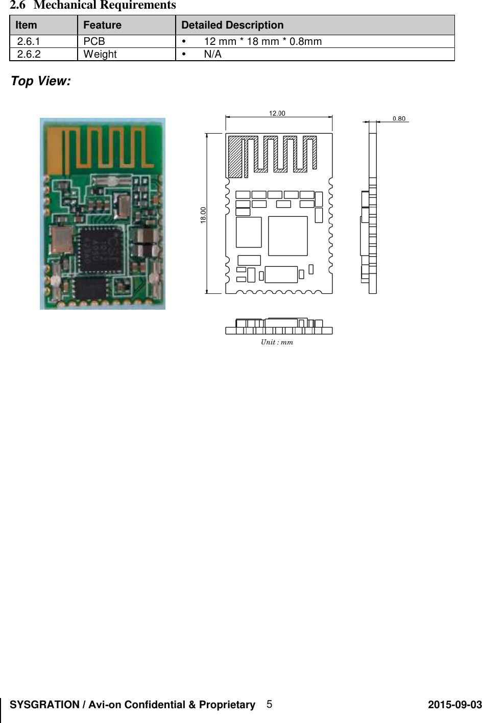
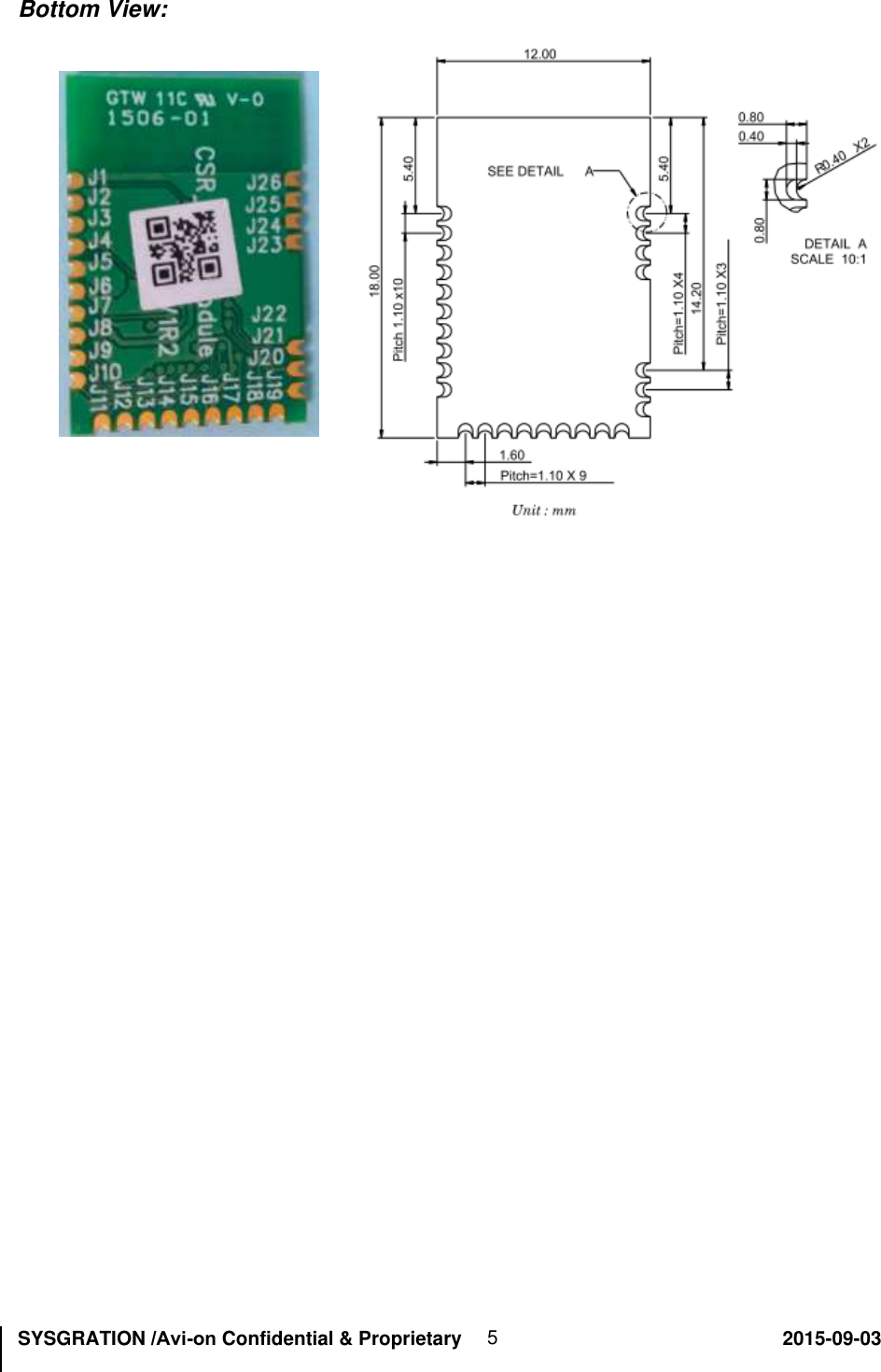
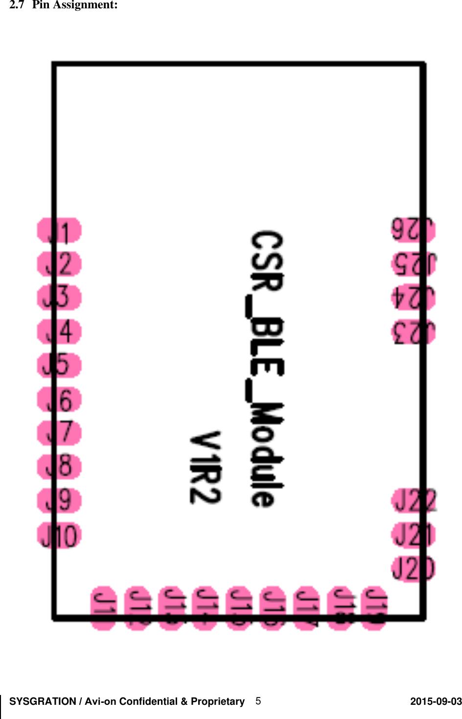
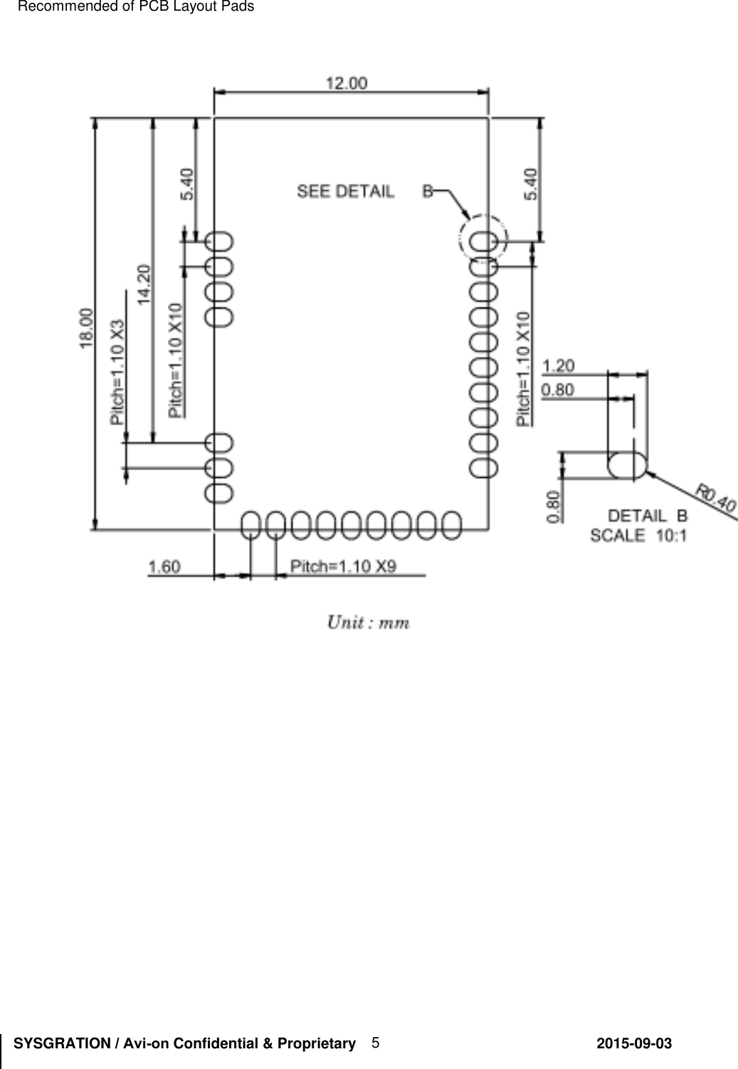
![SYSGRATION /Avi-on Confidential & Proprietary 2015-09-03 5 Pin Assignment Description: Pins Name Function Description J1 WAKE I Input to wake CSR1012 from hibernate or dormant. Default is pull-down. J2 XTAL_32K_IN Analog in 32.768KHz installed, Disconnect all to this Pin. J3 XTAL_32K_OUT Analog In 32.768KHz installed, Disconnect all to this Pin. J4 I2C_SCL I/O SPI serial flash installed, or I2C clock Input / output. J5 VBATT Power Power input. J6 I2C_SDA I/O SPI serial flash installed, or I2C data Input / output. J7 SPI_PION I Selects SPI debug or Programmable I/O, Pull-High : SPI debug Pull-down: Programmable I/O line, default is. J8 PIO[11] I/O Programmable I/O J9 PIO[10] I/O Programmable I/O J10 PIO[9] I/O Programmable I/O J11 SPI_MISO O SPI data output or Programmable I/O J12 SPI_MOSI I SPI data input or Programmable I/O J13 SPI_CSB I SPI select or Programmable I/O J14 SPI_CLK I/O SPI clock or Programmable I/O J15 PIO[4] I/O Programmable I/O J16 VDD_PADS Power Positive supply for all digital I/O ports J17 PIO[3] I/O Programmable I/O J18 UART0_RX I UART RX or Programmable I/O J19 UART0_TX O UART TX or Programmable I/O J20 AIO[0] I/O Analogue Programmable I/O J21 AIO[1] I/O Analogue Programmable I/O J22 AIO[2] I/O Analogue Programmable I/O J23 GND Ground Ground J24 GND Ground Ground J25 GND Ground Ground J26 GND Ground Ground](https://usermanual.wiki/Sysgration/SY-SHE-M-001/User-Guide-2743881-Page-5.png)